
5600HS - Flash KONICA MINOLTA - Free user manual and instructions
Find the device manual for free 5600HS KONICA MINOLTA in PDF.


| Product Type | Electronic Flash |
| Brand | Konica Minolta |
| Model | 5600HS |
| Guide Number | 56 (ISO 100, meters) |
| Zoom Coverage | 24mm to 85mm (auto zoom) |
| TTL Compatibility | Konica Minolta film cameras (A-type) |
| Flash Modes | TTL, Auto, Manual, Stroboscopic |
| Recycling Time | Approx. 0.5–6 seconds (fresh alkaline) |
| Number of Flashes | Approx. 200–800 (fresh alkaline) |
| Power Source | 4 × AA batteries (alkaline or NiMH) |
| Bounce Head | Tilt up 90°, down 15°; swivel left/right 180° |
| AF Assist Beam | Yes, red beam |
| Dimensions (W×H×D) | Approx. 77 × 105 × 135 mm |
| Weight | Approx. 350 g (without batteries) |
| Maintenance | Wipe with dry cloth; avoid moisture and dust |
| Safety | Do not disassemble; avoid heat sources; use only specified batteries |
| Spare Parts | Battery holder, sync cord (optional), external power pack (optional) |
| Reparability | Limited; service by authorized centers recommended |
Frequently Asked Questions - 5600HS KONICA MINOLTA
User questions about 5600HS KONICA MINOLTA
0 question about this device. Answer the ones you know or ask your own.
Ask a new question about this device
Download the instructions for your Flash in PDF format for free! Find your manual 5600HS - KONICA MINOLTA and take your electronic device back in hand. On this page are published all the documents necessary for the use of your device. 5600HS by KONICA MINOLTA.
USER MANUAL 5600HS KONICA MINOLTA
E INSTRUCTION MANUAL
FOR PROPER AND SAFE USE
Read and understand all warnings and cautions before using this product.
WARNING
Batteries may become hot or explode due to improper use.
- Use only the batteries specified in this instruction manual.
- Do not install the batteries with the polarity (+/-) reversed.
- Do not subject batteries to fire or high temperatures.
- Do not attempt to recharge (except for rechargeable batteries), short, or disassemble.
- Do not mix batteries of different types, brands, or ages.
- Tape over lithium battery contacts to avoid short-circuit when disposing of batteries, and follow local regulations for battery disposal.
Keep batteries or things that could be swallowed away from young children. Contact a doctor immediately if an object is swallowed.
Immediately remove the batteries and discontinue use if..
- the product is dropped or subjected to an impact in which the interior is exposed.
• the product emits a strange smell, heat, or smoke.
Do not disassemble. Electric shock may occur if a high voltage circuit inside the product is touched. Take your flash to a Minolta Service Facility when repairs are required.
CAUTION
Do not touch the flashtube during operation, it may become hot when the flash fires.
This device complies with Part 15 of the FCC Rules. Operation is subject to the following two conditions: (1) This device may not cause harmful interference, and (2) this device must accept any interference received, including interference that may cause undesired operation. Changes or modifications not approved by the party responsible for compliance could void the user's authority to operate the equipment.
This equipment has been tested and found to comply with the limits for a Class B digital device, pursuant to Part 15 of the FCC Rules. These limits are designed to provide reasonable protection against harmful interference in a residential installation. This equipment generates, uses and can radiate radio frequency energy and, if not installed and used in accordance with the instructions, may cause harmful interference to radio communications.
However, there is no guarantee that interference will not occur in a particular installation. If this equipment does cause harmful interference to radio or television reception, which can be determined by turning the equipment off and on, the user is encouraged to try to correct the interference by one or more of the following measures:
- Reorient or relocate the receiving antenna.
- Increase the separation between the equipment and the receiver.
- Connect the equipment to an outlet on a circuit different from that to which the receiver is connected.
- Consult the dealer or an experienced radio/TV technician for help.
This Class B digital apparatus complies with Canadian ICES-003.
CONTENTS
CAMERAS AND FLASH UNITS....6
NAMES OF PARTS....8
BASIC OPERATION
INSTALLING BATTERIES 12
Checking Batteries 13
ATTACHING AND REMOVAL....14
AUTO POWER ON/OFF AND FILM....15
P MODE FLASH: THE BASICS 16
Flash Range 18
EXPOSURE MODES 19
A Mode Flash 19
S Mode Flash 19
M Mode Flash 20
Flash Sync Speed....21
APPLICATIONS
ZOOM FLASH COVERAGE....23
TEST-FLASH/MODELING FLASH 26
BOUNCE FLASH....28
CLOSE-UP PHOTOGRAPHY (DOWNWARD BOUNCE) 31
DATA PANEL ILLUMINATOR 32
AF ILLUMINATOR ....33
MODE AND SELECT BUTTONS ....34
MANUAL FLASH (M)....36
HIGH-SPEED SYNC (HSS) 38
WIRELESS/REMOTE FLASH MODE ....40
Types Of Wireless/Remote Flash 41
Wireless Flash Range 42
Notes On Wireless Flash 44
[1] Using The Built-In Flash 46
[2] Using Two Flash Units 48
[3] Using Wireless Remote Flash Controller ....52
CONNECTING CAMERA AND FLASH BY CABLE ....55
SETTING POWER LEVEL (LEVEL)....58
MULTIPLE FLASH (MULTI)....60
RESET TO THE DEFAULT SETTINGS....64
CUSTOM FUNCTION....65
Wireless channel setting
Flash range units (m/ft)
Time to auto power off
Time to auto power off when using wireless
Exposure modes in which manual flash and multiple flash may be set
APPENDIX
USE IN COMBINATION WITH OTHER PRODUCTS ....69
ACCESSORIES....72
CAUTIONS WHILE HANDLING....74
PERFORMANCE....76
Thank you for purchasing the MAXXUM/PROGRAM FLASH 5600HS (D).
The MAXXUM/PROGRAM FLASH 5600HS (D) provides the maximum guide number 56, a high-intensity light source, and a wide range of functions in a compact body, and is designed for use with Minolta auto-focus single lens reflex cameras.
Please read this manual thoroughly before using this flash. We hope that you will continue to be satisfied by our products.
CAMERAS AND FLASH UNITS
Cameras
This manual covers the PROGRAM/MAXXUM FLASH 5600HS (D) as attached to one of the following cameras.
Maxxum
9, 7, 800si, 700si, 600si, 400si, 300si, XTsi, HTsi, STsi, QTsi Dynax
9, 7, 800si, 700si, 600si, 505si, 505siSuper, 500si, 500siSuper, 404si, 303si, 300si
When attaching to another Maxxum series camera, a Dynax series camera, a Vectis series camera, or a Dimâge series digital camera, read the main section of this manual while referring to 'Use in Combination with Other Products' on page 69.
Flash Units
For convenience, classify the following as D flash units when using multiple flash units for wireless flash photography, etc.
MAXXUM/PROGRAM FLASH 5600HS (D) MAXXUM/PROGRAM FLASH 3600HS (D)
This flash unit is designed and manufactured solely for use with the Minolta Maxxum/Dynax series cameras. It cannot be attached to other Minolta cameras. Performance when used with cameras from other manufacturers cannot be guaranteed. Minolta takes no responsibility for accidents or malfunctions due to use with such cameras.
The information in this manual is relevant for products introduced before August 2000. Contact the nearest authorized Minolta Service Facility to obtain information for products released after this date.

This mark below the flashtube certifies that this product meets the requirements of the EU (European Union) concerning interference causing equipment regulations. CE stands for conformité Européenne (European conformity).
NAMES OF PARTS
Flash Unit Diagram Control Panel
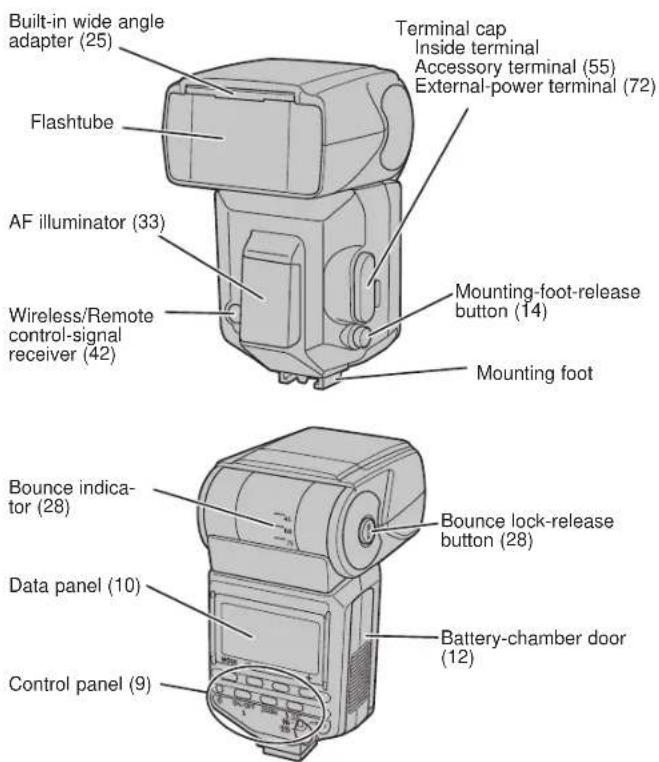
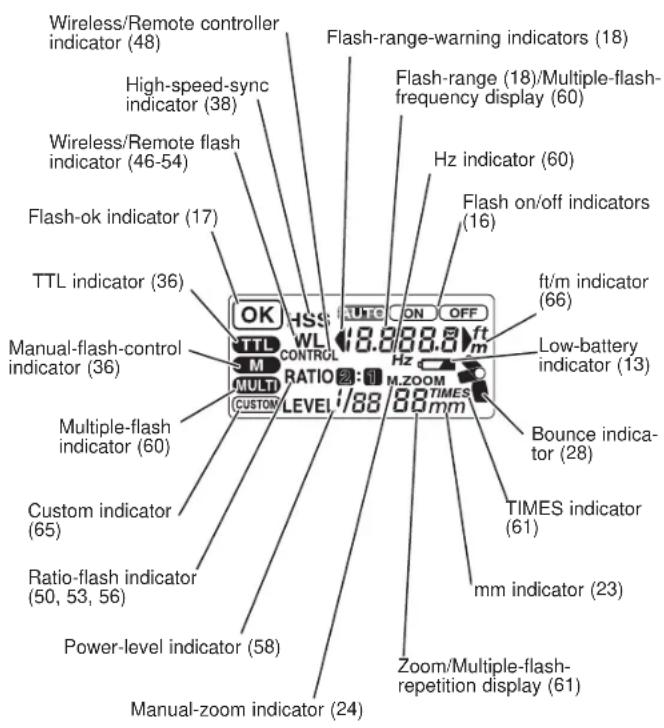
Figures in brackets after each item indicate the relevant page.
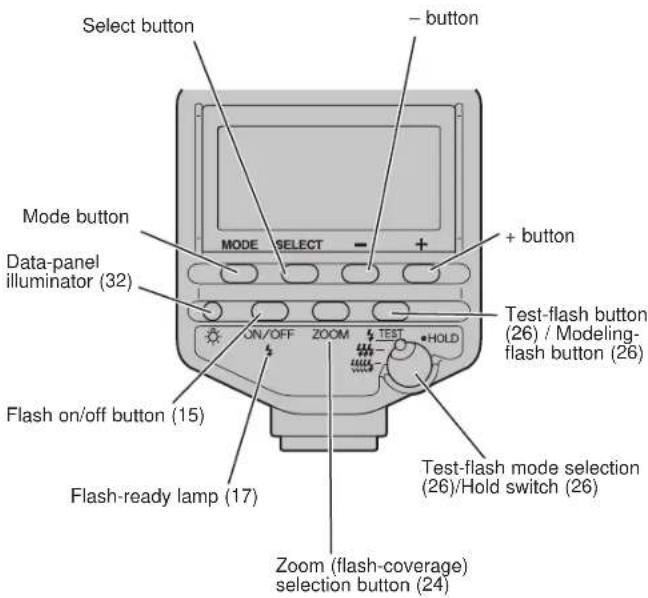
NAMES OF PARTS
Data Panel
BASIC OPERATION
The section explains preparations for use of the flash, and the basic details of taking photos.
- Automatic flash generates a flash only as necessary. Fill flash generates a flash with each photo.
INSTALLING BATTERIES
The 5600HS (D) may be powered by :
• Four AA-size alkaline batteries
• Four AA-size lithium batteries
- Four AA-size rechargeable nickel-metal hydride (Ni-MH) batteries Always ensure that rechargeable nickel-metal hydride batteries are charged in the specified charger unit.
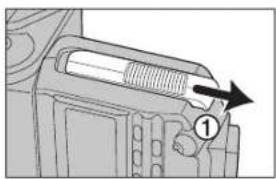
natural_image
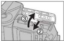
Mechanical component diagram showing a piston-like structure with an arrow pointing to a specific part (no text or symbols present)- Open the battery-chamber door as shown.
natural_image
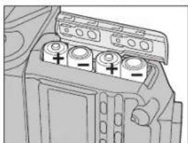
Diagram of a battery pack with three labeled cells (no text or symbols)- Insert the batteries according to the diagram in the battery chamber.
- Close the battery-chamber door.
- The indicators appear on the data panel. Press the flash on/off button if it doesn't appear.
Checking Batteries
The indicator on the data panel blinks when the batteries are low.
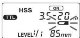
Power is low. The batteries will need to be replaced soon. Flash recycling time may be slow.
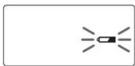
Insert new batteries. Flash cannot be used.
- Check the orientation of the batteries if nothing appears when the flash on/off button is pressed.
ATTACHING AND REMOVAL AUTO POWER ON/OFF AND FILM
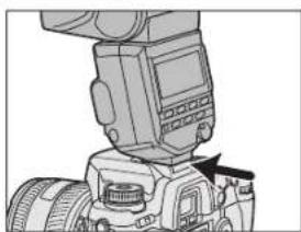
Attaching To The Camera
natural_image
Close-up of a camera module with no visible text or symbolsPush the mounting foot firmly onto the camera until it stops.
- The flash is locked in place automatically.
- If the built-in flash in the camera is protruding, lower it before fitting the flash unit.
Removing From The Camera
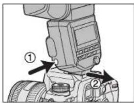
While pressing the mounting-foot release button ①remove the flash ②.
Auto Power On
Power is supplied to this flash automatically (auto power on) in the following situations.
- When the camera is used with the flash attached.
- When the flash on/off button is pressed.
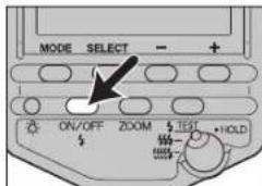
Flash on/off button
Auto Power Off
Power is switched off and data panel indicators disappear automatically to save the batteries when the camera or flash is not used for four minutes (auto power off).
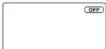
- When the flash is switched off (right diagram), the data panel indicator will disappear after eight seconds, or after 60 minutes in the case of wireless flash (p. 40).
- Custom settings may be used to change the time of auto power off, or to disable auto power off (p. 65).
Film
Do not use high-speed film (rating in excess of ISO 1000) with TTL direct metering (TTL ayed on the data panel, p. 36). Use of such film increases the exposure error.
- The low-speed film limit is the same as that for the films specified for the camera. See the camera manual for details.
P MODE FLASH: THE BASICS
- Select the P mode on the camera.
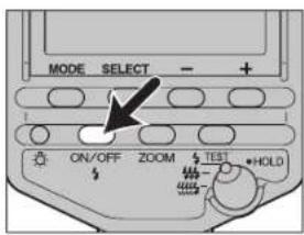
- Press the flash ON/OFF button to display ON ON
- Press the shutter-release button partway down.
• and appear with automatic flash. Only appears with fill flash.
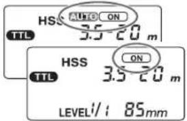
- With the Maxxum/Dynax 7, automatic flash is used with Full-auto, and fill flash when the P mode is selected.
- With the Maxxum/Dynax 9 and 800si, fill flash is used when the P mode is selected (automatic flash may also be selected as a custom setting with the 800si).
- With other cameras, automatic flash is used when the P mode is selected. Fill flash may be selected in the same way as the built-in flash in the camera.
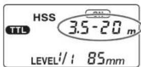
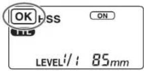
- Press the shutter-release button partway down and check that the subject is within the flash range.
• See page 18 for details of the flash range. - When the flash is charged, press the shutter-release button to take the photo.
- The flash is charged when indicators on the rear of the unit and in the camera viewfinder are both lit.
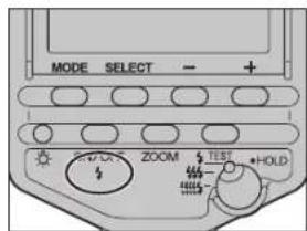
When the correct exposure has been obtained for the photo just taken:
displayed in the data panel for approximately four seconds.
- The indicator blinks in the camera viewfinder.
- The photo will be under-exposed if taken before charging is complete.
- When a photo is taken immediately after charging is complete while using slide film, it may be under-exposed near the farther limit of the flash range (p. 18).
- Press the shutter-release button after checking that charging is complete when using the flash with the self-timer.
Continued on next page
P MODE FLASH: THE BASICS
Flash Range
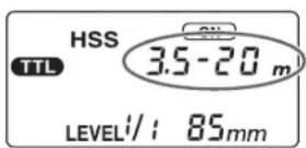
Press the shutter-release button part-way down to display the flash range for the proper exposure on the data panel. Check that the subject is within this range and then take the photo.
A distance range of 1.5\~28m may be displayed on the data panel (0.7\~28m for downward bounce, see p. 31). When the distance is outside this range, or is lit at both sides of the viewfinder.
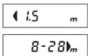
Proper exposure is obtained at less than 1.5m.
Proper exposure is obtained from 8m to 28m or more.
- The flash range is not shown when using flash bounce above and to left or right, with wireless flash, or when off-camera cables are used.
- When photographing beyond lower limit of the flash range, the photo may be over-exposed despite being displayed, or the bottom of the picture may become darker. Always photograph within the indicated flash range.
EXPOSURE MODES
This photography is only possible with cameras having the A, S, and M modes.
A Mode Flash
- Select the A mode on the camera.
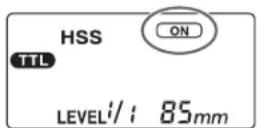
- Press the flash on/off button to display ON.
- Fill flash is selected.
-
Set the aperture and focus the subject.
-
Reduce the aperture (ie increase the f-stop) to reduce the flash range, or open the aperture (ie reduce the f-stop) to increase the flash range.
• The shutter speed is automatically set. -
Press the shutter-release button when charging is complete.
S Mode Flash
- Select the S mode on the camera.
- Press the flash on/off button to display ON
- Fill flash is selected.
-
Set the shutter speed, and focus the subject.
-
A shutter speed faster than the sync speed cannot be selected with the Maxxum STsi and Dynax 404si.
-
The shutter speed is set automatically with the Dynax 500si, 500siSuper, and Maxxum 400si.
-
Press the shutter-release button when charging is complete.
EXPOSURE MODES
M Mode Flash
- Select the M mode on the camera.
- Press the flash on/off button to display ON
- Fill flash is selected.
-
Set the aperture and shutter speed, and focus the subject.
-
Reduce the aperture (ie increase the f-stop) to reduce the flash range, or open the aperture (ie reduce the f-stop) to increase the flash range.
-
A shutter speed faster than the sync speed cannot be selected with the Maxxum STsi, 400si, and Dynax 500si, 500siSuper, and 404si.
-
Press the shutter-release button when charging is complete.
FLASH SYNC SPEED
Flash photography is generally associated with a maximum shutter speed referred to as the flash sync speed. This restriction does not apply to cameras designed for high-speed sync (HSS) photography, since they allow flash photography at the maximum shutter speed of the camera. Sync speeds and high-speed sync for each camera are as follows.
-
Maxxum/Dynax 9:
1/300 sec, high-speed sync photography possible
• Maxxum/Dynax 7, 800si, 700si, 600si:
1/200 sec, high-speed sync photography possible
• Maxxum XTsi, HTsi, and Dynax 505si, 505siSuper:
1/125 sec, high-speed sync photography possible
1/90 sec, high-speed sync photography impossible -
Maxxum STsi, QTsi, 400si, 300si, and Dynax 500si, 500siSuper, 404si, 303si, 300si:
APPLICATIONS
The section explains the various methods available to make full use of the flash unit.
ZOOM FLASH COVERAGE
Auto Zoom
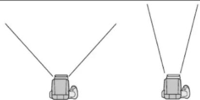
natural_image
Two identical diagrams of a mechanical device with two arms and three legs, no text or symbols present.24mm focal length 85mm focal length
This flash unit employs auto zoom to cover a range of focal lengths from 24mm to 85mm. There is normally no need to manually adjust zoom coverage.
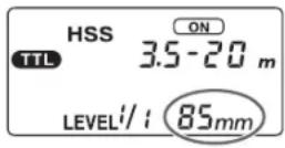
- Press the shutter-release button part-way down to display the automatic zoom coverage on the data panel.
• Automatic zoom coverage is set as follows:
| Focal length in use | Coverage |
| 24 - 27mm | 24mm |
| 28 - 34mm | 28mm |
| 35 - 49mm | 35mm |
| 50 - 69mm | 50mm |
| 70 - 84mm | 70mm |
| 85mm or more | 85mm |
- [24mm] blinks when a lens having a focal length of less than 24mm is used with auto zoom. Use of the built-in wide-angle adapter (p. 25) is recommended in this case to prevent darkening at the periphery of the image.
ZOOM FLASH COVERAGE
Manual Zoom
Zoom may be set manually irrespective of the focal length currently in use.
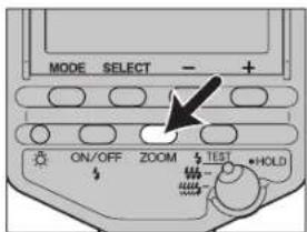
Press the ZOOM button to display the desired zoom coverage.
- Zoom coverage is changed in the following order. Auto zoom, 24mm, 28mm, 35mm, 50mm, 70mm, 85mm
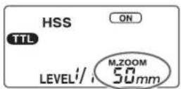
• [M.ZOOM] is displayed above zoom coverage when zoom is set manually.
- The periphery of the image darkens when a zoom coverage less than the focal length currently in use is set.
Built-In Wide Angle Adapter (17mm zoom angle)
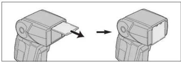
Pull-out the built-in wide-angle adapter for the 17mm zoom angle.
Pull out the adapter.
natural_image
Diagram showing two mechanical components with directional arrows indicating movement or assembly (no text or symbols present)- The zoom coverage display on the data panel shows [17mm]. The flash range is also displayed. - When flat subjects are photographed from the front with very wide-angle lenses such as the 17-35mm f/3.5G lens at the wide-angle setting, the distance between the lens and the center and periphery varies so that the amount of light from the periphery is slightly reduced.
TEST-FLASH/MODELING FLASH
One or more test flashes may be tried before photographing. This is particularly convenient for checking shadows when the flash is separated from the camera such as in wireless flash.
* Modeling flash is used to check shadows on the subject before taking photos.
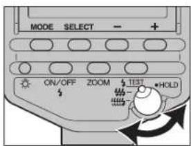
- Set the test-flash mode selection/hold switch to the desired mode.
Flash once at the set light level (LEVEL 1/1\~1/32).
- Use this test-flash mode when a flash meter is used in manual flash mode (p. 36).
- In multiple flash mode (p. 60), while pressing the test-flash button, the flash fires the number of times you have set.
Flash three times at a rate of two flashes per second (guide number 5.6 at 24mm position).
• Used to verify overall shadow.
Flash 4 seconds at a rate of 40 flashes per second (guide number 1.4 at 24mm position).
- Convenient for verifying detailed shadow for macro photography.
HOLD The setting prevents mis-operation.
- Photographs may be taken, however all flash operations, except use of the test-flash button and data panel illuminator, are locked.
-
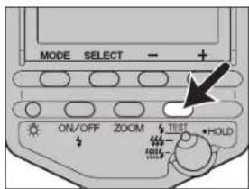
Press the test-flash button (modeling-flash button) when charging is complete.
-
Do not release the shutter while the flash is in use.
- The strength of shadows will differ from that during actual photography.
- Shadows will be lighter when using the flash in bright areas or outdoors, or when using bounce flash, and verification will therefore be more difficult.
BOUNCE FLASH
natural_image
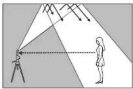
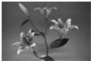
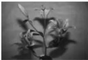
Diagram showing a person using a telescope to observe light from a tripod, with another person observing nearby (no text or symbols present)Strong shadows appear when flash is used with a wall directly behind the subject. In such cases the flash is directed at the ceiling etc. so that the subject is illuminated with reflected light, and the intensity of the shadows are reduced to produce a softer light in the photograph.
natural_image
Black-and-white close-up of flowering plant leaves and blossoms (no text or symbols)Bounce flash Normal flash
natural_image
Black-and-white photo of a plant with multiple leaves and stems, no visible text or symbols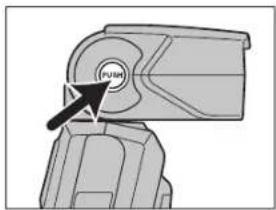
natural_image
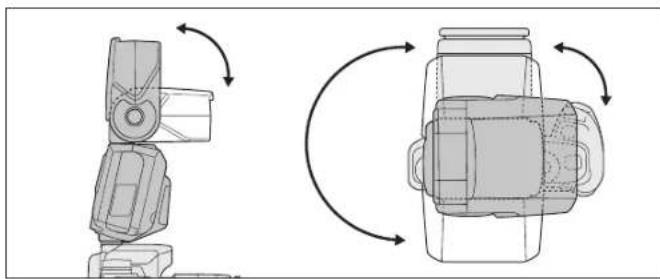
Mechanical component with a labeled 'Pulse' button (no other text or symbols)Rotate the flash towards the ceiling or left and right while pressing the bounce lock-release button.
natural_image
Technical line drawing of a mechanical device with rotational arrows indicating motion (no text or symbols)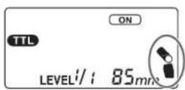
- The bounce indicator appears on the data panel.
The flash may be set to the following angles.
- Upwards: 45^ , 60^ , 75^ , 90^
- Downwards: 10^ (see 'Close-up Photography' p. 31)
• Right: 30°, 45°, 60°, 75°, 90° -
Left: 30^ , 45^ , 60^ , 75^ , 90^ , 120^ , 150^ , 180^
-
The bounce lock engages at the 0^ position. The lock-release button need not to be pressed when the flash is returned to the original position.
- The flash range is not displayed on the data panel when the flash is rotated upwards or left and right. High-speed sync is also cleared.
- Use a white ceiling or wall to reflect the flash. A colored surface may color the light. High ceilings or highly reflective surfaces such as glass are not recommended.
Continued on next page
BOUNCE FLASH
CLOSE-UP PHOTOGRAPHY (DOWNWARD BOUNCE)
Adjusting Bounce Angle
An unsightly photo results when both direct light and bounced light from the flash are used simultaneously. Determine the bounce angle in reference to the distance to the reflective surface, the distance from the camera to the subject, and the focal length of the lens etc.
Correct
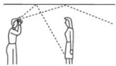
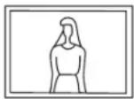
Incorrect
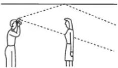
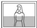
When flash is bounced upwards
Determine the angle in relation to the table at right.
| Focal length of lens | Bounce angle |
| 70mm minimum 45° | |
| 28~70mm | 60° |
| 28mm maximum 75°, 90° | |
Bouncing to Left and Right
Rotating the flash by 90^ to bounce light sideways is recommended. If an angle of less than 90^ is used, care should be taken to ensure that direct light from the flash does not illuminate the subject.

natural_image
Illustration of a hand spraying water onto a potted plant, with no text or symbols present.Tilt the flash slightly downwards when photographing objects between 0.7m and 1.5m from the camera to ensure accurate illumination.
natural_image
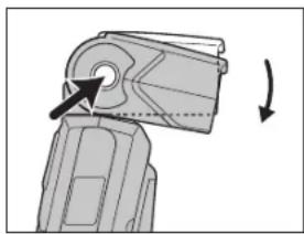
Mechanical device with a circular component and directional arrow indicating rotation (no text or symbols)Rotate the flash downwards while pressing the bounce lock-release button.
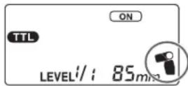
- The downward bounce indicator appears on the data panel.
- The rotation angle is 10^ .
- When photographing at a distance closer than 0.7m , the flash will not be able to completely cover the subject and the bottom of the picture will be darker. Use an off-camera or macro flash.
DATA PANEL ILLUMINATOR AF ILLUMINATOR
Illuminates the data panel at low-light levels.
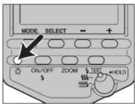
Press the data panel illuminator.
• The data panel is illuminated for approximately eight seconds. This period is extended if the flash is used during this time.
- To extinguish the data panel illuminator, press the button again while the data panel is illuminated.
natural_image
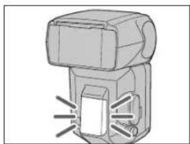
Diagram of a mechanical device with no visible text or symbolsIn low-light or when subject contrast is low, pressing the shutter-release button partway down for autofocus lights the red lamp on the front of the flash unit. This is the AF illuminator used as an aid in autofocusing.
- The AF illuminator is suitable for use with local focus areas on all cameras having wide focus areas.
• The AF illuminator operates even when the flash is off. - The camera AF illuminator does not operate while the flash AF illuminator is operating.
- The AF illuminator does not operate when continuous AF is used in the focusing mode (when continually focusing on a moving subject).
- The AF illuminator may not operate when the focal length of the lens is greater than 300mm. It will not operate when the flash is off-camera, or when the AF macro-zoom 3X-1X lens is used.
MODE AND SELECT BUTTONS
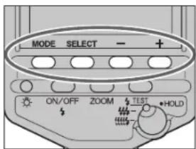
The mode, select, +, and - buttons are used to select the functions described on the next page.
The functions are selected with the following basic procedure. See the relevant pages for details.
- Select the major item with the mode button.
- Select the minor item with the select button.
- Make the setting with the + and - buttons.
- Press the select button* repeatedly until blinking stops.
* Also possible with the mode button or flash on/off button.
| Selected with mode button | Selected with select button | Selected with + and - buttons (items in Italics are initial settings) |
| TTL (36) | HSS (38) | ON, OFF |
| WL (40) | OFF, ON, CONTROL | |
| RATIO | OFF, 2:1, 2:1 | |
| LEVEL (58) | 1/1, 1/2, 1/4, 1/8, 1/16, 1/32 | |
| M (36) | HSS (38) | ON, OFF |
| WL (40) | OFF, ON | |
| LEVEL (58) | 1/1, 1/2, 1/4, 1/8, 1/16, 1/32 | |
| MULTI (60) | Hz | 100, 50, 40, 30, 20, 10, 9, 8, 7, 6, 5, 4, 3, 2 |
| TIME | -- (unlimited), 40, 35, 30, 25, 20, 15, 10, 9, 8, 7, 6, 5, 4, 3, 2 | |
| LEVEL | 1/8, 1/16, 1/32 |
Figures in brackets after each item indicate the relevant page.
- Pressing the + and -buttons simultaneously for three seconds restores the initial settings (p. 64).
- Multiple settings which are prohibited are not displayed. For example, as HSS cannot be selected with RATIO set to ③:1HSSis1 not displayed when the select button is pressed if RATIO is on.
MANUAL FLASH (M)
Normal TTL flash metering automatically adjusts the flash intensity to provide the proper exposure for the subject. Manual flash provides a fixed flash intensity irrespective of the brightness of the subject and the camera setting.
- Manual flash operates in the camera's M (manual) mode only. TTL measuring is selected automatically in other modes.
- As manual flash is not affected by the reflectivity of the subject, it is convenient for use with subjects with extremely high or low reflectivity.
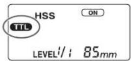
TTL flash metering
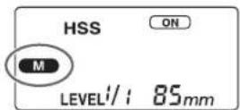
Manual flash metering
- Select the M mode on the camera.
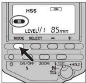
- Press the mode button to display 📄 the data panel.
- The modes change in the following order.

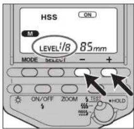
- Press the + or - button to select the power level to be set.
• The power level can be selected from the following. 1/1, 1/2, 1/4, 1/8, 1/16, 1/32
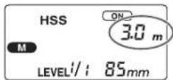
- When the shutter-release button is pressed partway down, the distance where the proper exposure will be obtained will appear in the data panel.
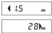
Proper exposure is obtained at less than 1.5m.
Proper exposure is obtained at more than 28m.
- The flash indicator is not displayed after a photo is taken with manual flash.
- ADI and pre-flash metering may be used with some camera-flash-lens combinations. Both ADI and pre-flash metering are handled as a type of TTL flash metering.
- Using custom functions, manual flash may be selected without setting the camera in the M mode (p. 66).
HIGH-SPEED SYNC (HSS)

natural_image
Black-and-white photo of a smiling person playing water with a water splash (no text or symbols visible)High-speed sync Normal flash
natural_image
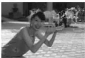
Black-and-white photo of a woman posing outdoors with a camera, no visible text or symbolsHigh-speed sync eliminates the restrictions of flash sync speed, and allows you to use flash over the entire shutter speed range of the camera. The selectable aperture range is increased, allowing portrait shots with flash in which the aperture is opened to leave back-grounds out of focus and thus accentuate the human subject.
- The Maxxum STsi, QTsi, 400si, 300si and Dynax 500si, 500siSuper, 404si, 303si, 300si do not support this function, and high-speed sync therefore cannot be used.
-
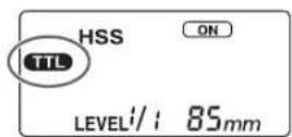
Press the mode button to display TTL or M on the panel.
-
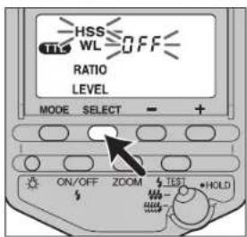
Press the select button to blink [HSS].
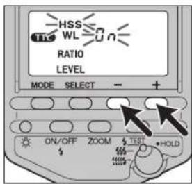
- The currently selected high-speed sync setting (8)naB5Blinks simultaneously.
-
Press the + or - button to select ☐n.
-
Press the select button repeatedly until blinking stops.
• [HSS] remains on the data panel.
- High-speed sync is cleared when it's selected with the procedure described above, and a shutter speed faster than the sync speed can no longer be set.
- It is recommended that photos be taken in bright locations. When photographing in dark areas the shutter speed will not exceed the sync data speed, even when it is selected.
- The flash range with high-speed sync is less than for normal flash photography. Check that the subject is within the displayed flash range before taking the photo.
- High-speed sync cannot be used with multiple flash, ratio flash, or bounce flash in the upwards, left, and right directions.
- When using a flash meter or color meter, high-speed sync cannot be used because it interferes with the proper exposure. Either select OFF to clear it, or select a shutter speed less than the sync speed.
WIRELESS/REMOTE FLASH MODE
natural_image
Black-and-white photo of a person sitting at a desk with a lamp in the background (no visible text or symbols)Normal flash
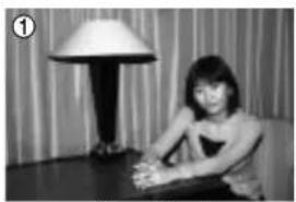
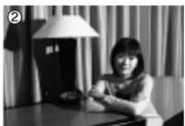
Photographs taken with the flash attached to the camera are flat as shown in photo ①n such cases, remove the flash from the camera and position it to obtain a more three-dimensional effect as shown in photo ②.
natural_image
Black-and-white photo of a woman sitting at a desk with a lamp and curtains in the background (no visible text or symbols)Wireless flash
Photo was taken using the camera's built-in flash and the flash located separately from the camera, with a light intensity of 1:2 respectively to produce a soft gradation between light and dark, and natural shadows. When taking this type of photograph with a single lens reflex camera, the camera and the flash unit are most commonly connected by cable. This flash eliminates the need for a cable to transmit signals to the flash unit by using the light of the flash itself as a signal. This type of flash control is referred to as 'wireless (remote) flash'. The proper exposure is determined automatically by the camera.
natural_image
Black-and-white photo of a woman sitting at a desk with a lamp and curtains in the background (no visible text or symbols)Wireless ratio flash
Types Of Wireless/Remote Flash
The following three types of wireless flash are supported.
natural_image
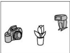
Simple line drawings of a camera, a potted plant, and a DSLR camera (no text or symbols)[1] Using the built-in flash (p. 46) The following two modes are available.
- Use only an off-camera flash unit (photo ②p. 40).
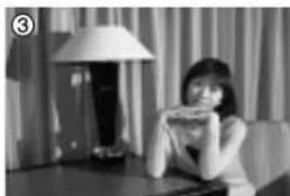
- Use the built-in flash, and an off-camera flash unit, to provide a light intensity ratio of 1:2 respectively (photo ③ p. 40).
Appropriate cameras and flash units:
• Any camera on page 6.
• A single 5600HS (D), 3600HS (D), 5400HS, 5400xi, or 3500xi.
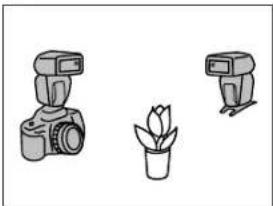
natural_image
Three line drawings of camera, a potted plant, and a pair of DSLRs (no text or symbols)[2] Using two flash units (p. 47)
The following two modes are available.
- Use only the off-camera flash unit (photo ②p. 40).
- Use one flash unit attached to the camera, and another off-camera flash unit, to provide a light intensity ratio of 1:2 respectively (photo ③p. 40).
Usable cameras and flash units:
• Maxxum/Dynax 9, 7, 800si, 700si, or 600si.
- Two 5600HS (D), 3600HS (D), 5400HS, or 5400xi, or one 5600HS (D), 5400HS, or 5400xi, and one 3600HS (D) or 3500xi.
Continued on next page
WIRELESS/REMOTE FLASH MODE
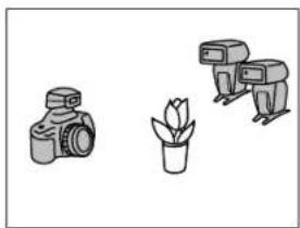
natural_image
Simple line drawings of three different objects: a camera, a potted plant, and a robot (no text or symbols)[3] Using the Wireless Remote Flash Controller (p. 52).
The following two modes are available.
- Use off-camera flash units (photo ② p. 40).
- Use two off-camera flash units to provide a light intensity ratio of 1:2 or 2:1.
Usable cameras and flash units:
• Maxxum/Dynax 9, 7, 800si, 700si, or 600si.
- A Wireless Remote Flash Controller and one or more 5600HS (D), 3600HS (D), 5400HS, 5400xi, or 3500xi.
Wireless Flash Range
The wireless flash uses a light signal from the built-in flash as a trigger to operate the off-camera flash unit. Follow the points below when positioning the camera, flash, and subject.
• Photograph in dark locations indoors.
- If you rotate the flashtube using bounce-flash function (p. 28) so that wireless/remote control-signal receiver points toward the camera, it will be easier for the flash to receive a signal from the camera.
- Install the off-camera flash within the gray area in the following diagram. See the flash unit manual for details of the distance between the flash and the subject (Table 2) for all except the 5600HS (D).
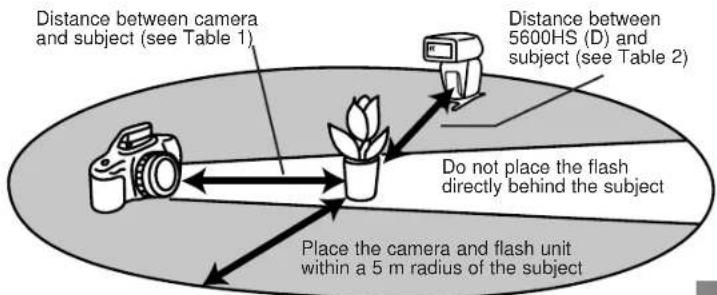
| Distance camera-subject (Table 1) | Distance 5600HS (D) - subject (Table 2) | |||||||
| Other than HSS | HSS | |||||||
| Shutter speed | All shutter speeds | Maximum 1/60 sec | 1/60~1/200 sec | 1/250 sec | 1/500 sec | 1/1000 sec | 1/2000 sec | 1/4000 sec |
| Aperture | ||||||||
| 2.8 | 1.4 - 5 | 1.4 - 5 | 1 - 5 | 1 - 5 | 1 - 3.5 | 1 - 2.5 | 1 - 1.7 | 1 - 1.2 |
| 4 | 1 - 5 | 1 - 5 | 1 - 5 | 1 - 3.5 | 1 - 2.5 | 1 - 1.7 | 1 - 1.2 | - |
| 5.6 | 1 - 5 | 1 - 5 | 1 - 5 | 1 - 2.5 | 1 - 1.7 | 1 - 1.2 | - | - |
Units: m
- The distances in the above table assume the use of ISO 100 film. If ISO 400 film is used the distances must be multiplied by a factor of two (assume a limit of 5m ).
- The flash range is not shown on the data panel with wireless flash.
WIRELESS/REMOTE FLASH MODE
Notes On Wireless Flash
- The MS-2 mini-stand is useful when the flash unit is off the camera. The mini-stand has a tripod configuration with a threaded hole to attach the flash unit.
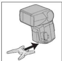
natural_image
Diagram of a mechanical device with an arrow indicating force or movement (no text or symbols present)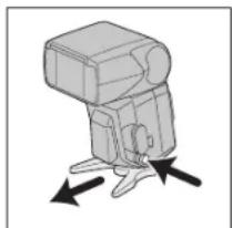
natural_image
Diagram of a camera flash unit with directional arrows indicating movement (no text or symbols)Attach Remove
- Pre-flash fires when wireless/remote flash mode is selected. A flash meter and color meter cannot be used.
- Test flash for the wireless/remote flash is in the currently selected test flash mode. Three flashes occur with and flashes continue for four seconds with time flash occurs at the HOLD position.
- Shutter speed is 1/60 or 1/45 of a second or less (this differs between cameras). Use with high-speed sync is possible only with the Maxxum/Dynax 7 in normal wireless mode (not ratio).
- The zoom position for the 5600HS (D) is automatically set to 24mm . Zoom position other than 24mm is not recommended.
- In wireless/remote flash mode, ADI metering and pre-flash metering will be canceled and TTL flash metering will be used automatically.
-
When slow sync is used with wireless flash, press the AE lock button to generate a test flash and take the photo while holding down the AE lock button.
-
Multiple flash cannot be used.
- When another wireless flash is being used nearby, the channel can be changed using custom settings, to prevent interference (p. 65).
- Make sure that RATIO is not displayed on the data panel of the off-camera flash except using with the Wireless Remote Flash Controller. If ratio is selected with the off-camera flash, proper exposure will not be obtained.
WIRELESS/REMOTE FLASH MODE
[1]-1 Using The Built-In Flash
natural_image
Simple line drawings of a camera, a potted plant, and a second camera (no text or symbols)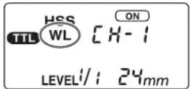
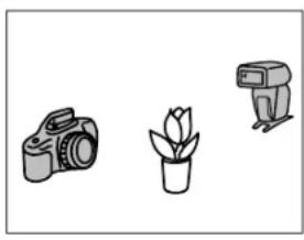
- Attach the 5600HS (D) to the camera and switch the flash and camera power supplies on.
-
Set the camera to wireless flash.
-
The method used for the setting varies with the camera. See the camera manual for details.
-
When the camera is set to wireless the 5600HS (D) is also set to wireless automatically, and WL is displayed on the data panel.
-
Remove the 5600HS (D) from the camera and raise the built-in flash.
- Set up the camera and the 5600HS (D).
• See page 43 for details.
-
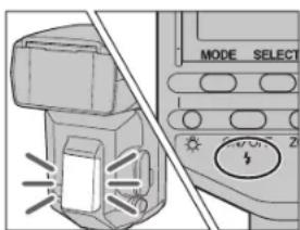
Check that the built-in flash and 5600HS (D) are fully charged.
-
is lit in the viewfinder when the built-in flash is fully charged.
-
The AF illuminator on the front blinks, and on the rear is lit, when the 5600 HS (D) is fully charged.
-
Use test flash to check the 5600HS (D) flash.
-
The method used for test flash differs with the camera used (eg. press the AE lock button, or spot AE lock button). See the camera manual for details.
-
If the test flash doesn't fire, change the position of the camera, flash, and subject, or point the wireless/remote control-signal receiver towards the camera.
-
Check again that the built-in flash and the 5600HS (D) are fully charged, and press the shutter-release button to take the photo.
[1]-2 Ratio-Flash Control Using The Built-In Flash
The built-in flash and 5600HS (D) may be controlled to a flash intensity of 1 and 2 respectively. See photo ☑ in page 40.
The method used differs with the camera. See the camera manual for details.
- Set shutter speed to 1/60 of a second or less (low shutter speed). Wireless high-speed sync photography cannot be used.
- Ratio-flash control cannot be used with the Maxxum QTsi, 300si, and Dynax 303si, 300si.
[1]-3 Setting Wireless/Remote Flash By Flash Only
If you keep using the same camera and the flash combination without changing the wireless channel, it will not be necessary to attach the flash to the camera the next time.
- Camera's setting : See the camera manual for detail.
- 5600HS (D)'s setting : Follow the step 1 to 5 in page 49.
- This procedure is not available with the Maxxum QTsi, 400si, 300si and the Dynax 500siSuper, 500si, 303si, 300si.
WIRELESS/REMOTE FLASH MODE
[2]-1 Using Two Flash Units
natural_image
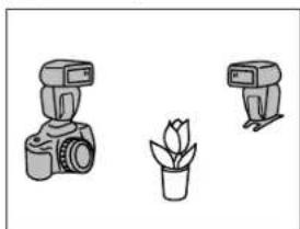
Illustration of three camera models: a DSLR camera, a potted plant, and a DSLR camera (no text or symbols)- Use two 5600HS (D), 5400HS, or 5400xi, or one 5600HS (D), 5400HS, or 5400xi, and one 3600HS (D) or 3500xi.
- Use Maxxum/Dynax 9, 7, 800si, 700si, or 600si.
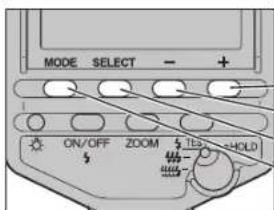
When two flash units are used, the unit attached to the camera is used as the controller, and the other as the off-camera flash.
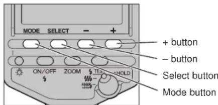
+ button - button Select button Mode button
Setting Up The Controller
(The following applies when the 5600HS (D) is used as the controller.)
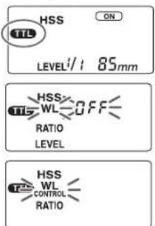
- Switch the 5600HS (D) on.
- Press the mode button to display TTL .
- Press the select button repeatedly to blink [WL].
- Press the + or - button to blink [WL CONTROL].
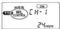
- Press the select button repeatedly until blinking stops.
- Attach the 5600HS (D) to the camera.
- The 5400HS or 5400xi may be used as the controller. See the flash unit manual if using the 5400HS. Display [W.L - C.1] if using the 5400xi.
Setting Up The Off-Camera Flash
(The following applies when the 5600HS (D) is used as the off-camera flash.)
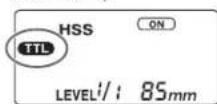
- Switch the 5600HS (D) on.
- Press the mode button to display TTL or M.
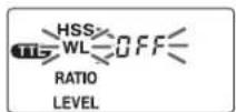
-
Press the select button repeatedly to blink [WL].
-
Press the select button repeatedly to blink [WL].
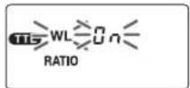
-
Press the + or - button to blink [WL On].
-
Press the + or - button to blink [WL On].
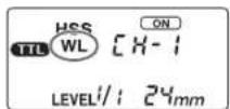
- Press the select button repeatedly until blinking stops.
- The 5400HS, 5400xi, or 3500xi may be used as the off-camera flash. See the flash manual if using the 5400HS. Display [W.L-F.1] if using the 5400xi. Press and hold the on/off button until wireless indicator glows if using the 3500xi. Continued on next page
Continued on next page
WIRELESS/REMOTE FLASH MODE
Taking Photos
- Set up a camera with a controller, and off-camera flash unit.
• See page 43 for details.
- When using the 5600HS (D) as the controller and a flash other than the D flash (see page 6) as the off-camera flash, ensure that the shutter speed does not exceed the flash sync speed for the camera. The off-camera flash will not operate if the shutter speed is greater than the sync speed.
- Check that both flash units are fully charged.
- The AF illuminator on the front blinks, and on the rear is lit, when the 5600HS (D) is fully charged.
-
Use test flash to check the off-camera flash.
-
The method used for test flash differs with the camera used (eg. press the AE lock button, or spot AE lock button). See the camera manual for details.
-
If the test flash doesn't fire, change the position of the camera, flash, and subject, or point the wireless/remote control-signal receiver towards the camera.
-
Check again that both flash units are fully charged, and press the shutter-release button to take the photo.
[2]-2 Ratio-Flash Control Using Two Flash Units
The controller and off-camera flash may be controlled to a flash intensity of 1 and 2 respectively. See photo ③n page 40.
- Ratio-flash control cannot be used with manual flash photography M.
Setting Up The Controller
(The following applies when the 5600HS (D) is used as the controller.)
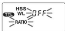
- Set up the 5600HS (D) with the wireless controller as described in 1\~4 on page 48.
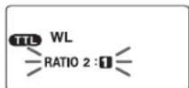
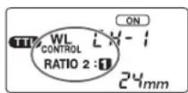
- Press the select button to blink [RATIO].
- Press the + or - button to select 2:1.
- Press the select button.
- Attach the 5600HS (D) to the camera.
Setting Up The Off-Camera Flash
Set up the off-camera flash as described on page 49. Manual flash M cannot be used.
Taking Photos
The same method is used as for photography without ratio-flash control (p. 50).
- Set shutter speed to 1/60 of a second or less (low shutter speed). Wireless high-speed sync photography cannot be used.
WIRELESS/REMOTE FLASH MODE
[3]-1 Using Wireless Remote Flash Controller
![KONICA MINOLTA 5600HS - [3]-1 Using Wireless Remote Flash Controller - 1](/content/2026/05/863656/images/05e7da7e37c30dfa376ad3a71907e49725f7c698892f08b2b758bb25b9e6d31f.jpg)
natural_image
Illustration of three camera models: a DSLR camera, a potted plant, and a multi-camera camera (no text or symbols)- The Wireless Remote Flash Controller and at least one 5600HS (D), 3600HS (D), 5400HS, 5400xi, or 3500xi is required.
- Use Maxxum/Dynax 9, 7, 800si, 700si, or 600si.
The Wireless Remote Flash Controller manual may state that it is for use only with the Maxxum/Dynax 9xi. However, it may be used with all the cameras listed above. As test flash differs between cameras, refer to the camera manual beforehand.
It may state that only the 5400xi and 3500xi flash units can be used, however the 5600HS (D) can be used in the same way as the 5400xi.
The 5600HS (D) is set up with the wireless flash as shown below.
![KONICA MINOLTA 5600HS - [3]-1 Using Wireless Remote Flash Controller - 3](/content/2026/05/863656/images/221e1a55c30ded5bd2570adb5c4d1caf2cc3e2d3bee1418066bc1cc0ef7fa2d9.jpg)
- Switch the 5600HS (D) on.
- Press the mode button to display
TTL or M.
![KONICA MINOLTA 5600HS - [3]-1 Using Wireless Remote Flash Controller - 4](/content/2026/05/863656/images/9e40f4188d2908e9996e66a3299fe761d006bf4a92680b5f4eff33f33dac83f7.jpg)
- Press the select button repeatedly to blink [WL].
- Press the + or - button to blink [WL On].
- Press the select button repeatedly until blinking stops.
Taking Photos
Refer to the Wireless Remote Flash Controller manual.
- Set shutter speed to 1/60 of a second or less (low shutter speed).
Wireless high-speed sync photography cannot be used.
[3]-2 Ratio-Flash Control Using Two Or More Flash Units
When using wireless flash with two or more program flash units, it is also possible to provide a flash intensity of 1 and 2 (or 2 and 1) respectively.
- Ratio-flash control is not possible with 3600HS (D) and 3500xi only, as ratio cannot be set with these flashes. Use with 5600HS (D), 5400HS, or 5400xi.
- Ratio-flash control cannot be used with manual flash photography M.
Using 5600HS (D), 5400HS, 5400xi only
(The following applies for 5600HS (D). See flash or Wireless Remote Flash Controller manual for other flashes.)
- Set up the 5600HS (D) with the off-camera flash as described in 1\~4 on page 52\~53.
Continued on next page
WIRELESS/REMOTE FLASH MODE
CONNECTING CAMERA AND FLASH BY CABLE
-
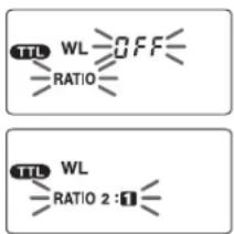
Press the select button to blink [RATIO].
-
Press the + or - button to select 2:1 for one flash, and for another.
-
The flash set to provides 1/3 of the whole light intensity. Flash provides 2/3 of the whole intensity.
- Do not set both flashes to the same ratio. Proper exposure may not be obtained.
- Press the select button.
Using with 3600HS (D) or 3500xi
Set up the 5600HS (D) with the wireless ratio off-camera flash in the same way as described in 1\~4 on page 53\~54, and select 2:1. Set up the 3600HS (D) or 3500xi with the wireless off-camera flash. (See flash or Wireless Remote Flash Controller manual for details.) Ratio is set to automatically, and provides 2/3 of the whole light intensity.
Taking Photos
Refer to the Wireless Remote Flash Controller manual.
- Set shutter speed to 1/30 of a second or less (low shutter speed).
natural_image
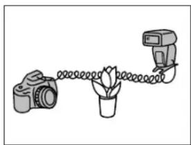
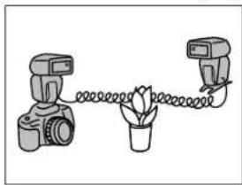
Simple line drawing of a camera, a potted plant, and a camera with a spring (no text or symbols)The use of the optional off-camera cables allows photography with the flash units separated from the camera. Up to four flash units can be connected. The ability to take photographs without the need to consider positioning of the flash units provides for considerable freedom to create a variety of shadow effects on the subject.
natural_image
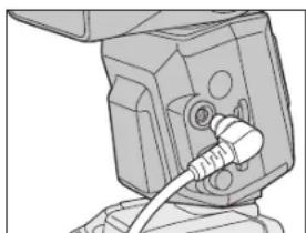
Technical line drawing of a mechanical component with a cable inserted (no text or symbols)- Flash units with accessory terminals can be connected directly. When connecting the 5600HS (D), remove the terminal cap and plug the cable into the accessory terminal.
Flash Units
Use the following flash units for off-camera flash photography by cable.
A group: 5600HS (D), 5400HS, 5400xi, 5200i
B group: 3600HS (D), 3500xi, 2000xi, 3200i, 2000i
- In this mode, ADI metering and pre-flash metering will be canceled and TTL flash metering will be used automatically.
Continued on next page
CONNECTING CAMERA AND FLASH BY CABLE
Equalizing The Power Level Of All Flash Units
All the flash units in A and B group can be used.
- Connect the flash units with off-camera cables.
- Switch all flash units on.
- Take the photo.
Flash-Ratio Control (varying the intensity of individual flash)
natural_image
Simple line drawing of a camera connected to a flower and a pair of cameras (no text or symbols)When using two or more flash units, it is possible to provide a flash intensity of 1 and 2 (or 2 and 1) respectively.
- Ratio control is not possible with B group flash units only (p. 55).
- Ratio control cannot be used with 300si, as proper exposure may not be obtained.
Set up the A group flash with ratio control. The following applies when the 5600HS (D) is used. See each flash manual for other flashes.
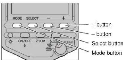
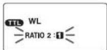
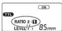
- Connect the flash units with off-camera cables.
- Switch all flash units on.
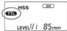
- Press the mode button on the 5600HS (D) to display 📋 the data panel.
-
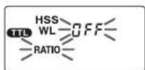
Press the select button repeatedly to blink [RATIO].
-
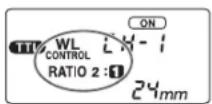
Press the + or - button to select 2:1 or 2:1.
-
If 2 is selected, it provides 1/3 of the whole light intensity. If 2t proveds 2/3 of the whole intensity.
-
Other flashes will provide the rest of the light intensity automatically.
-
Press the select button repeatedly until blinking stops.
-
Take the photo.
SETTING POWER LEVEL (LEVEL)
The power level for the flash can be adjusted.
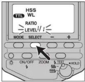
1. Press the select button to display [LEVEL] on the data panel.
• The current level is displayed.
- This step may be ignored when manual flash M:lected.
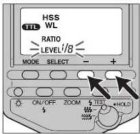
2. Press the + or - button to select the power level to be set.
- With TTL or manual flash photography the power level may be selected from the following.
1/1, 1/2, 1/4, 1/8, 1/16, 1/32 - With multiple flash photography the power level may be selected from the following.
1/8, 1/16, 1/32
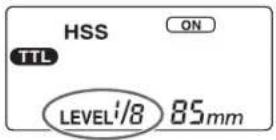
3. Press the select button.
- When the power level is changed, the distance displayed on the data panel changes accordingly.
- Power level settings can be set independently for TTL photography TTL, manual flash photography and multiple photography MULTI. When switching between these, the flash will remember your setting for each individual mode.
- In TTL flash photography, the power level will be adjusted with the selected level its maximum.
- In manual flash photography, if the power level is set at 1/1, then the flash will fire at full power. If set at 1/2, it will fire at half power, etc.
- When the power level is changed, the distance displayed on the data panel changes accordingly.
- Power level settings can be set independently for TTL photography TTL, manual flash photography and multiple photography MULTI. When switching between these, the flash will remember your setting for each individual mode.
- In TTL flash photography, the power level will be adjusted with the selected level its maximum.
- In manual flash photography, if the power level is set at 1/1, then the flash will fire at full power. If set at 1/2, it will fire at half power, etc.
MULTIPLE FLASH (MULTI)
natural_image
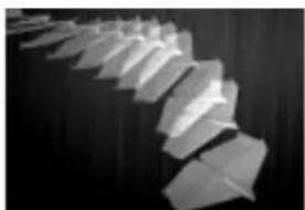
Black and white photo of a staircase with wooden panels arranged in a row (no text or symbols visible)The flash is triggered a number of times while the shutter is open. Multiple flash allows motion of the subject to be captured in a photograph for later analysis.
- The camera must be set to the M (manual) mode for multiple flash photography. Multiple flash cannot be used unless the camera supports the M mode.
- Set the camera to the M mode.
- Press the mode button to display a data panel.
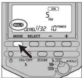
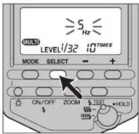
- Press the select button to blink [Hz].
- The current multiple flash frequency (flashes per second) is displayed on the data panel.
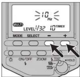
- Press the + or - button to select the flash frequency.
• The flash frequency may be selected from the following.
100, 50, 40, 30, 20, 10, 9, 8, 7, 6, 5, 4, 3, 2, 1
- Press and hold the + or - buttons to change the value rapidly.

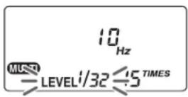
- Press the select button to blink [TIMES].
- The current number of flashes for multiple flash is displayed on the data panel.
- Press the + or - button to
select the number of flashes.
- The number of flashes may be selected from the following. --, 40, 35, 30, 25, 20, 15, 10, 9, 8, 7, 6, 5, 4, 3, 2
- Press and hold the + or - buttons to change the value rapidly.
- When -- is selected flashes continue at the set frequency while the shutter is open.
Continued on next page
MULTIPLE FLASH (MULTI)
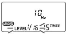
- Press the select button to blink [LEVEL] on the data panel.
- The current power level is displayed.
- Press the + or - button to select the power level to be set.
• The power level may be selected from the following. 1/8, 1/16, 1/32
- Press the select button.
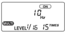
10. Set the shutter speed and aperture.
- The shutter speed is calculated as follows to suit the selected flash frequency and number of flashes. Number of flashes (TIME) ÷ Flash frequency (Hz) ≤ Shutter speed. For example, when ten flashes and 5Hz are selected, 10 ÷ 5 = 2 requires a shutter speed of longer than two seconds.
11. When the flash is fully charged, press the shutter-release button to take the photo.
- The distance at which the proper exposure is obtained with a single flash is displayed on the data panel.
- To prevent shaking, the use of a tripod is recommended during multiple flash photography.
- Test flash will fire at the selected frequency/number/level while the test-flash button is being pressed if the selection switch is at for HOLD.
- The use of custom settings allows the camera to be set up for manual flash photography without selecting the M mode (p. 66).
Maximum Number Of Continuous Flashes
The maximum number of continuous flashes during multiple flash photography is limited by the charge in the battery. Use the following values as a guide.
With alkaline batteries
| Power level | Flash frequency (Hz) | ||||||||||||||
| 1 | 0 | 0 | 5 | 0 | 4 | 0 | 3 | 0 | 2 | 0 | 1 | 0 | 9 | 8 | |
| 1/8 | 3 | 4 | 4 | 4 | 5 | 5 | 5 | 5 | 5 | 6 | 6 | 7 | 7 | 7 | 1 |
| 1/16 | 5 | 6 | 7 | 8 | 8 | 9 | 9 | 1 | 0 | 1 | 0 | 1 | 0 | 1 | 0 |
| 1/32 | 10 | 10 | 10 | 15 | 15 | 20 | 20 | 25 | 30 | 40* | 40* | 40* | 40* | ||
With nickel-metal hydride batteries
| Power level | Flash frequency (Hz) | ||||||||||||||
| 1 | 0 | 0 | 5 | 0 | 4 | 0 | 3 | 0 | 2 | 0 | 1 | 0 | 9 | 8 | |
| 1/8 | 3 | 4 | 4 | 4 | 5 | 5 | 5 | 5 | 5 | 6 | 6 | 7 | 7 | 1 | 0 |
| 1/16 | 5 | 6 | 7 | 8 | 8 | 9 | 9 | 1 | 0 | 1 | 0 | 1 | 0 | 1 | 0 |
| 1/32 | 10 | 15 | 15 | 15 | 20 | 25 | 25 | 30 | 40 | 40* | 40* | 40* | 40* | 40* | |
*40 signifies more than 40.
- The maximum number of flashes varies with the type of battery and its condition. If the external battery pack EP-2 is used, the maximum number of flashes increases beyond the values given above.
CUSTOM FUNCTIONRESET TO DEFAULT SE
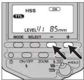
Most of the flash functions return to the default settings, as follows, if both the + button and - button are pressed and held for three seconds.
| Item | Settings | Page |
| Flash on/off | On (Auto on or on) | 15 |
| Flash coverage (zoom) | Auto zoom (85mm) | 23 |
| Flash mode (TTL/M/MULTI) | TTL | 36 |
| High speed sync (HSS) | On | 38 |
| Wireless/remote flash (WL) | Off | 40 |
| Ratio control (RATIO) | Off | - |
| Power level in TTL/M | 1/1 | 58 |
| Power level in multiple flash | 1/32 | 62 |
| Frequency in multiple flash (Hz) | 5 | 60 |
| Repetition in multiple flash (TIMES) | 10 | 61 |
The various flash settings may be changed as necessary. The following five items may be changed.
- Wireless channel setting (channels 1\~4)
- Flash range units (m/ft)
• Time to auto power off (4 minutes, 15 minutes, 60 minutes, none)
• Time to auto power off when using wireless (60 minutes, none) - Exposure modes in which manual flash and multiple flash may be set (M mode only, all modes)
![WL [X-1] CUSTOM MODE SELECT = + ON/OFF ZOOM TEST HOLD](/content/2026/05/863656/images/560fc32845c31530eb3403c7f2d23866006567f4dd959d16ecd3188afe362e4f.jpg)
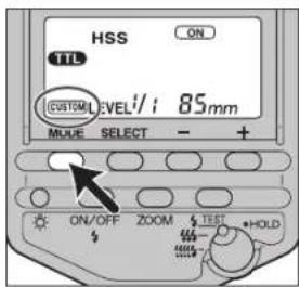
- Press the select button for 3 seconds.
- The first item (wireless channel setting) is displayed.
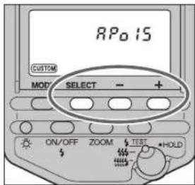
- Press the select button to select the item, and press the + or - button to select the desired setting.
• Each time the select button is pressed, the next of the five items appears on the data panel (see following page).
Continued on next page
CUSTOM FUNCTION
Select with the + button or - button
1. Wireless channel setting
![WL [X-1] [X-2] [X-3] [X-4] CUSTOM](/content/2026/05/863656/images/371a21461a993bbbfa940b1482269954e29dacd19ed9460a4ea0c0aecd8be15d.jpg)
Channel 1 Channel 2
Channel 3 Channel 4
2. Flash range units (m/ft)
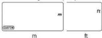
3. Time to auto power off

4 minutes 15 minutes 60 minutes none
4. Time to auto power off when using wireless
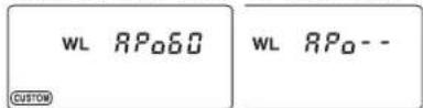
60 minutes none
5. Exposure modes in which manual flash and multiple flash may be set
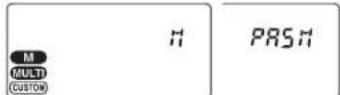
M mode only All modes
3. Press the mode button.
- The data panel returns to the original display.
-
When the setting other than the default setting is selected in custom 3, 4 or 5, contains on the data display.
-
After changing the wireless flash channel (see 1. Wireless channel setting), fit the flash to the camera, and press the shutter-release button partway down to transmit the flash channel information to the camera.
- When 'All modes' is selected (see 5. Exposure modes in which manual flash and multiple flash may be set) manual flash and multiple flash photography may be used in all exposure modes. The setting is provided for the sake of convenience, however the proper exposure may not be obtained with photography in other than the M mode, and it is therefore recommended that the M mode be used.
- The selected settings are maintained even when the flash unit is switched off, or the battery is removed.
APPENDIX
USE IN COMBINATION WITH OTHER PRODUCTS
Read this manual in combination with the relevant manual when any of the following products are used in combination with the 5600HS (D).
Using xi Series Single Lens Reflex Cameras
(Maxxum/Dynax 9xi, 7xi, 5xi, 3xi, SPxi, 2xi)
- Flash is automatic in the P mode with the 9xi, 7xi, 5xi and 3xi. Fill flash may also be selected. See the camera manual for details.
- Flash is automatic in the P mode with the SPxi and 2xi. Fill flash cannot be selected.
- The shutter speed is set automatically in the S mode with the 7xi, 5xi, 3xi, SPxi, and 2xi.
• High-speed sync cannot be used. - As the 9xi has no built-in flash, only [2] and [3] on page 41 and 42 may be used for wireless flash. Use the AE lock button for test flash.
- Wireless photography with the 7xi, 5xi, and 3xi is possible only with [1] on page 41 (Using The Built-In Flash). See the camera manual for details of taking photographs.
- Test flash for the wireless flash cannot be used while Eye-start is in use.
- Select Channel 1 when using wireless flash with the 3xi.
- Wireless flash cannot be used with the SPxi and 2xi.
Using i Series Single Lens Reflex Cameras
(Maxxum/Dynax 8000i, 7000i, 5000i, 3000i)
- Flash is automatic in the P mode. Fill flash may also be selected with the 8000i. See the camera manual for details.
- Flash is automatic in the S mode, and the shutter speed is set automatically.
• High-speed sync and wireless flash cannot be used. - As the proper exposure may not be obtained with the 5000i and 3000i, off-camera ratio flash control cannot be used.
USE IN COMBINATION WITH OTHER PRODUCTS
Using Early AF Series Single Lens Reflex Cameras
(Maxxum/Minolta 9000, 7000, 5000)
- The optional flash shoe adapter FS-1200 is necessary. See the FS-1200 manual for details.
Using APS Single Lens Reflex Cameras
(Vectis S-1, S-100)
- Flash is automatic in the P mode. Fill flash may be selected with the flash-mode button on the camera.
- The shutter speed is set automatically in the S mode.
• High-speed sync cannot be used. - Wireless photography is possible only with [1] on page 41 (Using The Built-In Flash). See the camera manual for details of taking photographs.
- As the S-100 is not equipped with an auto lock accessory shoe, the flash unit cannot be attached to the camera. Use with wireless flash. Ratio-flash control cannot be used. Set to Channel 1.
- APS film (new system) differs in size from 35mm film, so that the flash coverage differs at the same focal length. This flash unit is designed for a flash coverage of 24mm with a focal length for 35mm film, so that when used with APS film focal length flash coverage is 19mm. For example, when the V Zoom 22-80mm f/4-5.6 lens is used the full flash coverage is available.
Using Minolta Digital Cameras
(Dimâge RD3000, Digital camera RD-175)
- Flash is automatic in the P mode. Fill flash is used when a photo is taken while the manual fill-flash button on the camera is pressed.
- The shutter speed is set automatically in the S mode.
• High-speed sync cannot be used. - As the RD3000 has no built-in flash, only [2] and [3] on page 41 and 42 may be used for wireless flash. Use the spot button for test flash.
- Wireless photography with the RD-175 is possible only with [1] on page 41 (Using The Built-In Flash). See the camera manual for details of taking photographs.
ACCESSORIES
Off-Camera Accessories
natural_image
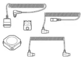
Illustration of various electrical connectors and components (no text or symbols)The following off-camera accessories are available.
- Off-camera cable
- Off-camera shoe
- Extension cable
- Cable CD
• Triple connector TC-1000
The off-camera cable allows the flash to be used from any position. Use of the extension cable allows of the distance from the camera to be further extended. Use of the cable CD and triple connector TC-1000 allows photography with multiple flash units.
- With the 5600HS (D), the off-camera cable may be connected directly to the flash accessory terminal without the need to use the off-camera shoe. Use the off-camera shoe when the flash is used on a tripod.
External Battery Pack EP-2 Set
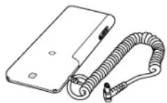
The external battery pack contains six AA-size alkaline batteries. It reduces charging time by half, and doubles the number of flashes possible.
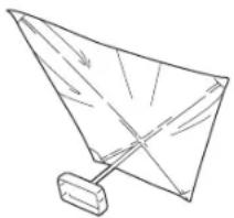
Bounce Reflector V Set
natural_image
Simple line drawing of a paper airplane with wings and a handle (no text or symbols)This reflector is attached to the 5600HS (D) flash for simple bounce illumination photography outdoors, and indoors where no reflective surfaces are available. The unit folds easily for convenient carrying.
- The flash range is not displayed on the data panel. High-speed sync is also cleared.
- If you already have Bounce Reflector Sets III or IV, it is only necessary to purchase the adapter. The reflector part is the same.
Use Of Other Accessories With The 5600HS (D)
- The control grip CG-1000 does not allow correct control, and therefore cannot be used with the 5600HS (D).
CAUTIONS WHILE HANDLING
During Photography
- This flash unit generates strong light, and should therefore not be used in front of the eyes.
Batteries
- Do not store the flash unit with the alkaline batteries inside it. Leakage from the batteries may damage the battery chamber.
- Due to the characteristics of alkaline batteries, temperature, and storage conditions, the battery level displayed on the data panel may be lower than the actual battery capacity. The displayed battery level will be restored to the correct value after the flash has been used a few times. When clicks to indicate that the flash cannot be used, pressing the flash on/off button in number of times may result in recovery of the battery. Replace the battery if it does not recover.
- When using the lithium batteries, if the batteries become hot due to high temperature or successive use, may blink and the flash may not be able to use for a while. Wait until the batteries become cold before using the flash again.
- Nickel-metal hydride batteries can lose power suddenly. If starts blinking or flash can no longer be used while taking pictures, change or recharge the batteries.
- Depending on the time elapsed since manufacture of the battery, the flash frequency and number of flashes for new batteries may differ from the values shown in the table.
Temperature
- The flash unit may be used over a temperature range of -20^ to 50^ .
- Do not leave the flash unit exposed extremely high temperatures (eg. direct sunlight inside motor vehicles), or in conditions of high humidity.
- The response of the data panel becomes slower as temperature decreases, and it becomes darker at high temperatures. Restore it to normal temperature if these problems occur.
- To prevent condensation from forming, place the camera in a sealed plastic bag when bringing it from cold environment to a warm environment. Allow it to come to room temperature before removing it from the bag.
- Battery capacity decreases at colder temperatures. Keep your camera and spare batteries in a warm inside pocket when shooting in cold weather. may blink even when there is some power left in the batteries in cold weather. Batteries will regain some of their capacity when warmed to normal operating temperature.
- This flash unit is not waterproof. Care is therefore required to ensure that it does not come into contact with water or sand when used near water. Contact with water, sand, dust, or salt content may result in a malfunction.
Maintenance
- Clean by wiping with a soft, clean cloth. If the flash has been in contact was sand, wiping will damage the surface, and it should therefore be cleaned gently using a blower.
- Do not use cleaners containing organic solvents (eg. thinners or benzene) under any circumstances.
PERFORMANCE
Guide number
Normal flash (ISO 100)
| Power level | Flash Coverage Setting (mm) | ||||||||
| 17 | 24 | 28 | 35 | 50 | 70 | 85 | |||
| 1/1 | 18 | 30 | 32 | 38 | 44 | 50 | 56 | ||
| 1/2 | 12 | 21 | 22 | 26 | 31 | 35 | 38 | ||
| 1/4 | 9 | 1 | 5 | 1 | 6 | 1 | 9 | 2 | 2 |
| 1/8 | 6.4 | 10 | 11 | 13 | 15 | 17 | 19 | ||
| 1/16 | 4.5 | 7.5 | 8 | 9 | 11 | 12 | 13 | ||
| 1/32 | 3.2 | 5.3 | 5.7 | 6.7 | 7.8 | 8.8 | 9.7 | ||
Wireless flash (ISO 100)
| Power level | Flash Coverage Setting (mm) |
| 17 24 28 35 50 70 85 | |
| 1/1 | 14 25 26 30 35 41 42 |
HSS flat flash (flash with HSS, ISO 100)
| Shutter speed | Flash Coverage Setting (mm) |
| 17 24 28 35 50 70 85 | |
| 1/250 | 6.7 12 13 15 17 19 22 |
| 1/500 | 4.5 8.6 9.5 10 12 13 16 |
| 1/1000 | 3.5 6 6.7 7.5 9 9.5 11 |
| 1/2000 | 2.4 4.3 4.5 5 6 6.7 8 |
| 1/4000 | 1.7 3 3.5 3.7 4.5 4.7 5.6 |
| 1/8000 | 1.2 2.1 2.4 2.5 3 3.5 4 |
| 1/12000 | 1 1.8 2 2.1 2.5 2.8 3.5 |
Frequency/Repetition
| Alkaline | Lithium | Nickel hydride | |
| Frequency (sec) | 0.2 - 11 0 | 2 - 13 0.2 - 8 | |
| Repetition (times) | 90 - 3200 | 250 - 8000 | 80 - 2800 |
- Repetition is the approximate number of times that are achieved before a new battery is completely flat.
Flash coverage
| Flash coverage | Flash Coverage Setting (mm) | ||||||||
| 17 | 24 | 28 | 35 | 50 | 70 | 85 | |||
| Top-bottom (°) | 1 | 1 | 5 | 6 | 0 | 5 | 3 | 4 | 5 |
| Left-right (°) | 125 | 78 | 70 | 60 | 46 | 36 | 31 | ||
Continuous flash performance
40 continuous cycles of 5 flashes per second (Normal flash, power level 1/32, nickel-metal hydride battery)
AF illuminator
Automatic flash at low contrast and low brightness For wide focus area Approximate operating range (with Maxxum/Dynax 7) AF mid 3 areas: 0.5 - 10m (24 - 105mm) AF top-bottom 6 areas: 0.5 - 5m (35 - 105mm)
Flash control
Flash control using pre-flash, TTL direct metering, manual flash
Size
370g (without batteries)
Specifications are based on the latest information available at the time of printing and are subject to change without notice.
MEMO
Printed in Japan
9222-8841-11 P-BOOK
© 2000 Minolta Co., Ltd. under the Berne Convention and universal Copyright Convention
Products Co., Ltd. 368 Minolta Road, Songjiang, Shanghai, China
Minolta Singapore (Pte) Ltd. 10, Taban Gardens Crescent, Singapore 608923
Minnesota Hong Kong Limited Room 208, 2/F, Eastern Center, 1065 Kings Road.
Head office 369 Britainia Road East, Mississauga, Otatiro L4Z 2H5, Canada Vancouver Branch 230-3771, Jacobs Road, Richmond Rd, G.V6V 219, Canada
Minnesota Canada Inc
Los Angeles Branch 11150 Hope Street Cyprss, CA 90630. U.S.A.
Head office 101 Williams Drive Ramsey New Jersey 07446 IL5A
Inova Corporation
Mínimo Portugal Limited Av. de Brasil 32 A B 1280 L, 1995.
Minolta Svenska AB Airbnban 114, S-1/1 sat Solna, Sweden
Minolta (Schweiz) AG Redürasse 6, CH-8953 Dietikon, Switzerland
Belgium Branch Pirms Bouldwinathan 1, B-2550 Konlich, Belgium
MioVita Camera Benelux B.V. Zenbachan 39, P.O. Box 6000, NL-3600 H.
Minnesota Australia Ges. m.b.H. Amallestrasse 59-61, A-1131 Wien, Australia
Moulla (UK) Limited 7 Tanzania Drive, Blacklands, Milton Keynes, MK14 SBU. England
Minnesota Europe semi-minorating 1.1 - U-3053 Larganagan, Germany
[Non-Text]
Minority Co., Ltd. 3-13, 2-Chome, Azuchi-Machi, Chuo-Ku, Osaka 541-8556, Japan
- FOR PROPER AND SAFE USE
- WARNING
- CAUTION
- CONTENTS
- CAMERAS AND FLASH UNITS
- Cameras
- Maxxum
- Flash Units
- NAMES OF PARTS
- BASIC OPERATION
- INSTALLING BATTERIES
- Checking Batteries
- ATTACHING AND REMOVAL AUTO POWER ON/OFF AND FILM
- Attaching To The Camera
- Push the mounting foot firmly onto the camera until it stops.
- Removing From The Camera
- Auto Power On
- Auto Power Off
- Film
- P MODE FLASH: THE BASICS
- Flash Range
- EXPOSURE MODES
- A Mode Flash
- S Mode Flash
- M Mode Flash
- FLASH SYNC SPEED
- APPLICATIONS
- ZOOM FLASH COVERAGE
- Manual Zoom
- Built-In Wide Angle Adapter (17mm zoom angle)
- TEST-FLASH/MODELING FLASH
- BOUNCE FLASH
- CLOSE-UP PHOTOGRAPHY (DOWNWARD BOUNCE)
- Adjusting Bounce Angle
- When flash is bounced upwards
- Bouncing to Left and Right
- DATA PANEL ILLUMINATOR AF ILLUMINATOR
- Press the data panel illuminator.
- MODE AND SELECT BUTTONS
- MANUAL FLASH (M)
- HIGH-SPEED SYNC (HSS)
- WIRELESS/REMOTE FLASH MODE
- Types Of Wireless/Remote Flash
- [3] Using the Wireless Remote Flash Controller (p. 52).
- Wireless Flash Range
- Notes On Wireless Flash
- Setting Up The Off-Camera Flash
- Taking Photos
- [2]-2 Ratio-Flash Control Using Two Flash Units
- Setting Up The Controller
- [3]-1 Using Wireless Remote Flash Controller
- [3]-2 Ratio-Flash Control Using Two Or More Flash Units
- Using 5600HS (D), 5400HS, 5400xi only
- CONNECTING CAMERA AND FLASH BY CABLE
- Using with 3600HS (D) or 3500xi
- Equalizing The Power Level Of All Flash Units
- Flash-Ratio Control (varying the intensity of individual flash)
- SETTING POWER LEVEL (LEVEL)
- Press the select button to display [LEVEL] on the data panel.
- Press the + or - button to select the power level to be set.
- Press the select button.
- MULTIPLE FLASH (MULTI)
- Set the shutter speed and aperture.
- When the flash is fully charged, press the shutter-release button to take the photo.
- Maximum Number Of Continuous Flashes
- CUSTOM FUNCTIONRESET TO DEFAULT SE
- CUSTOM FUNCTION
- Select with the + button or - button
- Wireless channel setting
- Flash range units (m/ft)
- Time to auto power off
- Time to auto power off when using wireless
- Exposure modes in which manual flash and multiple flash may be set
- Press the mode button.
- APPENDIX
- USE IN COMBINATION WITH OTHER PRODUCTS
- Using xi Series Single Lens Reflex Cameras
- Using i Series Single Lens Reflex Cameras
- Using Early AF Series Single Lens Reflex Cameras
- Using APS Single Lens Reflex Cameras
- Using Minolta Digital Cameras
- ACCESSORIES
- Use Of Other Accessories With The 5600HS (D)
- CAUTIONS WHILE HANDLING
- During Photography
- Batteries
- Temperature
- Maintenance
- PERFORMANCE
- Printed in Japan
- 9222-8841-11 P-BOOK
Brand : KONICA MINOLTA
Model : 5600HS
Category : Flash