
E222782 - Office ELO - Free user manual and instructions
Find the device manual for free E222782 ELO in PDF.


| Product Type | Touchscreen Monitor |
| Model Number | E222782 |
| Brand | Elo |
| Display Size | 22 inches (diagonal) |
| Resolution | 1920 x 1080 (Full HD) |
| Touch Technology | PCAP (Projected Capacitive) |
| Brightness | 250 cd/m² |
| Contrast Ratio | 1000:1 |
| Viewing Angle | 178° / 178° |
| Connectivity | HDMI, VGA, USB-B (touch), USB-A (pass-through) |
| Power Supply | AC 100-240V, 50/60Hz, external adapter |
| Power Consumption (Typical) | 30W |
| Stand Adjustability | Tilt: -5° to +90°, VESA mount compatible (100x100mm) |
| Dimensions (with stand) | 20.4" x 13.1" x 8.3" (518 x 333 x 211 mm) |
| Weight (with stand) | 12.5 lbs (5.7 kg) |
| OS Compatibility | Windows, macOS, Linux, Chrome OS |
| Certifications | FCC, CE, UL, RoHS |
| Cleaning Instructions | Use a soft, dry cloth; avoid abrasive cleaners or liquids directly on screen |
| Warranty | 3 years limited |
Frequently Asked Questions - E222782 ELO
User questions about E222782 ELO
0 question about this device. Answer the ones you know or ask your own.
Ask a new question about this device
Download the instructions for your Office in PDF format for free! Find your manual E222782 - ELO and take your electronic device back in hand. On this page are published all the documents necessary for the use of your device. E222782 by ELO.
USER MANUAL E222782 ELO
natural_image
Modern tablet with a blue abstract background and radial light effect (no text or symbols visible)USER MANUAL
Elo Touch Solutions
ESY15i2 15.6" Windows I-Series AiO Interactive Signage
ESY22i2 21.5" Windows I-Series AiO Interactive Signage
ESY15i5 15.6" Windows I-Series AiO Interactive Signage
ESY22i5 21.5" Windows I-Series AiO Interactive Signage
UM600086 Rev. A
Copyright © 2016 Elo Touch Solutions, Inc. All Rights Reserved.
No part of this publication may be reproduced, transmitted, transcribed, stored in a retrieval system, or translated into any language or computer language, in any form or by any means, including, but not limited to, electronic, magnetic, optical, chemical, manual, or otherwise without prior written permission of Elo Touch Solutions, Inc.
Disclaimer
The information in this document is subject to change without notice. Elo Touch Solutions, Inc. and its Affiliates (collectively "Elo") makes no representations or warranties with respect to the contents herein, and specifically disclaims any implied warranties of merchantability or fitness for a particular purpose. Elo reserves the right to revise this publication and to make changes from time to time in the content hereof without obligation of Elo to notify any person of such revisions or changes.
Trademark Acknowledgments
Elo, Elo (logo), Elo Touch, Elo Touch Solutions, and TouchPro are trademarks of Elo and its Affiliates. Windows is a trademark of Microsoft Corporation.
Table of Contents
Read this first 5
Product Description 7
Precautions....7
I-Series Layout....8
Elo Expansion Module (optional for POS capability) Layout...... 9
Chapter 2: Getting Started....11
Unpacking the Windows I-Series AiO Interactive Signage .... 11
General Mounting Information 12
Rear VESA Mount 13
Chapter 3: Operation.... 14
General Information 14
Front OSD Control Buttons.... 14
L.E.D. Functionality – POWER LED 15
L.E.D. Functionality – Wireless LAN LED 15
L.E.D. Functionality – Ethernet LED (i2 product shown)...... 16
Using the Input/output Panel (i2 product shown) 16
Setting Up the Operating System 16
Creating the Recovery Flash Drive.... 19
Recovering the Operating System 23
Chapter 4: Options and Upgrades ...... 26
Optional Peripherals Kits 26
Magnetic Stripe Reader Kit (E001002) 26
Near Field Communication Kit (E001004) 28
Barcode Reader Kit (E093433) 30
I-Series 15.6" Stand Kit (E044162) 32
I-Series 21.5" Stand Kit (E044356) 33
I-Series Wall Mount Kit (E143088).... 34
Chapter 5: Technical Support.... 34
Trouble Shooting for Common Problems.... 35
Technical Assistance 35
Chapter 6: Safety & Maintenance .... 36
Safety....36
I-Series Care and Handling 37
Waste Electrical & Electronic Equipment 38
Chapter 7: Regulatory Information.... 39
Before using the I-Series for Windows, read the important safety and handling information (this section), Safety & Maintenance (Chapter 6), Regulatory Notice (Chapter 7), and the Warranty Information (Chapter 8) chapters in this user manual.
This section provides guidance on the safe handling and use of your I-Series for Windows. Please read to understand all of the details.
ENERGY STAR Support information
Your touchcomputer is ENERGY STAR ^® qualified. Elo is a partner in the Environmental Protection Agency's (EPA) ENERGY STAR® Program and has designed the computer to meet the latest ENERGY STAR® guidelines for energy efficiency. Your touchcomputer ships with the power management options preset to a configuration that will provide the most stable operating environment and optimum system performance.

To conserve energy, your computer is set to dim the display after 5 minutes of inactivity, and enter the low-power Sleep mode which shuts down the system after 30 minutes of inactivity. We recommend that you leave this and other energy saving features active, so that your touchcomputer will operate at its maximum energy efficiency. You can wake the touchcomputer from Sleep mode by pressing the power button.
When considering additions to your business, purchase products that have earned the ENERGY STAR ^® for all your equipment needs, which can save your money, save energy, and help protect the climate.
Visit http://www.energystar.gov or http://www.energystar.gov/powermanagement for more information regarding the ENERGY STAR® Program.
Important safety and handling information
To avoid personal injury, property damage, or accidental damage to your Elo I-Series for Windows (hereafter referred to as the I-Series or touchcomputer), please read through all of the information provided in this section before using the I-Series.
For detailed operating instructions, refer to the I-Series User Manual (this publication).
Protect your data and software:
Do not delete or change the name of files or directories that were not created by you; as this may prevent the I-Series software from operating properly.
Be aware that accessing network resources can render your I-Series vulnerable to computer viruses, hackers, spyware, and other malicious activities that might damage your I-Series, software, or data. It is your responsibility to ensure that your I-Series has adequate protection in the form of firewalls, antivirus software, and anti-spyware software and keep them up to date.
Keep electrical appliances such as an electric fan, radio, high-powered speakers, air conditioner, and microwave oven away from your I-Series because the strong magnetic fields generated by these appliances can damage the screen and the data on the I-Series.
Take precautions with plastic bags:
The I-Series comes with plastic packaging material.
DANGER: Plastic bags can be dangerous. Keep plastic bags away from babies and children to avoid danger of suffocation.
Chapter 1: Product Overview
This chapter provides an overview of the new Elo I-Series for Windows, including the locations of the connectors and controls, I-Series features, accessories, specifications, and operating environment.
Product Description
The new Elo I-Series for Windows combines Elo reliable performance with the latest developments in touchscreen technology and display design. This combination creates a natural flow of information between a user and the I-Series for Windows.
The I-Series for Windows provides a powerful, compact, and configurable interactive display in two screen sizes: 15.6-inch, and 21.5-inch. These models are ruggedized and available with our industry-leading Elo touch technology: TouchPro® PCAP (projective capacitive). Both 15" and 22" I-Series models integrate with 1920x1080 LCD panel to provide superior display performance for displaying images and running applications. The i2 models are fan-less — well-suited for environments where noise may be an issue. The i5 models with the 6^th generation Intel® Core™-i5 processor and HD530 graphics are fan-cooled and deliver superior performance when needed.
The I-Series for Windows have a compact, stylish design, with a choice of configuration and customer-installable peripheral options as well as ease of serviceability. These models support multiple memory and storage configurations as well as optional accessories for purchase from Elo.
Precautions
Follow all warnings, precautions and maintenance tips as recommended in this user manual to maximize the life of your unit and prevent risks to user safety. See Chapter 6 for more information on safety.
This manual contains information that is important for the proper setup and maintenance of the I-Series for Windows. Before setting up and powering on your new I-Series, please read through this manual in detail seriously and carefully.
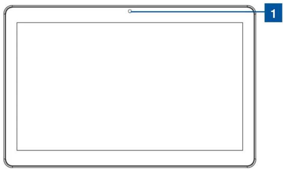
ESY I-Series 15.6"/21.5" Models (i2 product shown)
natural_image
Simple line drawing of a tablet device with a blue indicator line and number 1 on the right (no text or symbols on the device itself)
natural_image
Front view of a server rack unit with multiple drive bays (no visible text or labels)I-Series 15.6"/21.5" front view (left) and clerk right side view (right)
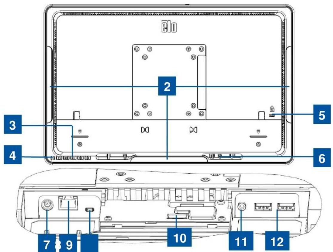
I-Series 15.6"/21.5" back view (top) and rear IO view (bottom)
| 1 | Camera 7 Power Connector (19V DC-IN) | |
| 2 | Peripheral Micro USB Ports 8 Ethernet LAN | Port |
| 3 | OSD Control Buttons 9 Micro HDMI | |
| 4 | Power indicator LED (top) Wireless indicator LED (bottom) | 10 Elo GPIO Connector |
| 5 | Kensington Lock 11 Audio Port (Line-out) | |
| 6 | Loops for Cable Ties 12 USB 3.0 Ports |
Elo Expansion Module (optional for POS capability) Layout
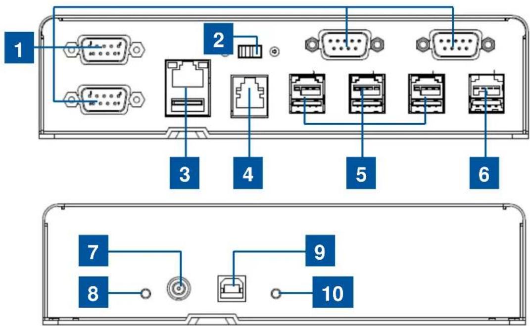
Elo expansion module front side view (Top), rear view (bottom).
| 1 | USB to Serial COM Ports 6 +24V Powered USB Port (Red) | ||
| 2 | 12V/24V Cash Drawer Power Switch 7 | 19V | DC Input |
| 3 | Ethernet LAN & USB Ports 8 Power LED | ||
| 4 | RJ11 Cash Drawer Port 9 USB Port to Host PC | ||
| 5 | +12V Powered USB Ports (Green) | 10 USB Connection LED | |
• 12V/24V Cash Drawer Power Switch
The user can switch the input power to the cash drawer with either 12V or 24V input.
• RJ11 Cash Drawer Port
The cash drawer port is a RJ-11 connector and the default setting is set to +24V. The pinouts is defined by the table below.
| Pin # | Signal Name | Pin # | Signal Name |
| 1 | GND | 2 | Channel1 |
| 3 | DETECT | 4 | POWER |
| 5 | Channel | 2 | 6 |
GND
Chapter 2: Getting Started
Unpacking the Windows I-Series AiO Interactive Signage
To unpack the I-Series:
-
Open the box.
-
Check that the following items are present and in good condition:
-
I-Series system unit.
- Quick Install Guide
-
AC/DC Power adapter.
•Power cable for North America, Europe, and U.K. -
Remove the protection bag/cover from the unit and film on display, desiccant packs, and other packaging materials appropriately. Please take extra caution to ensure they are not accessible by small children.
-
Press the power button to start using the I-Series.
Windows I-Series
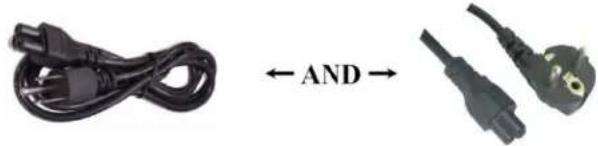
Power cable US/Canada Power cable Europe
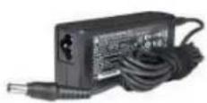
Quick Install Guide Power Adapter
The I-Series for Windows system material package.
The system following the VESA pattern described in the following section.
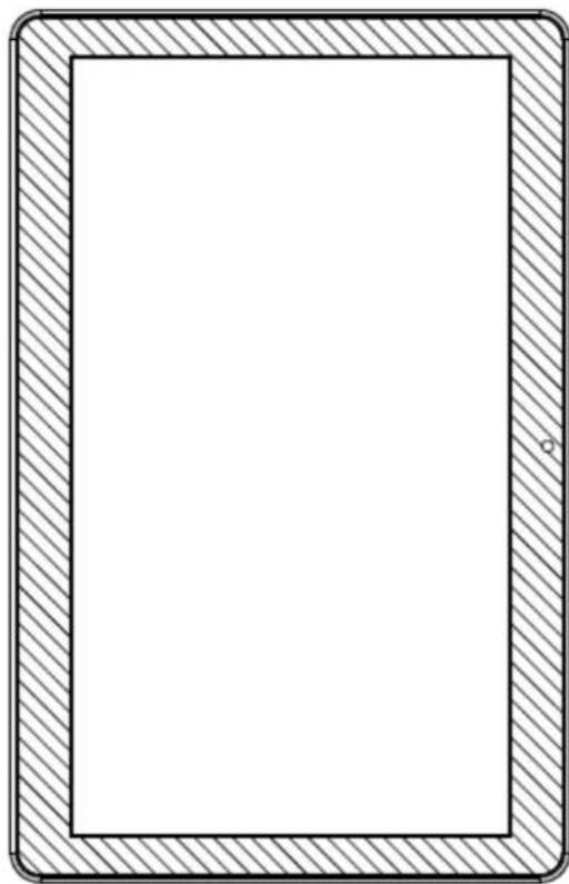
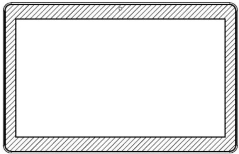
The following three mounting orientations are supported: Landscape, portrait and table top (except i2 models) mode. For optimal touch performance, ensure that the system is supported fully and is as flat as possible.
natural_image
Blank rectangular frame with hatched border, no text or symbols presentPortrait
natural_image
Blank rectangular frame with hatched border and small circular mark at top (no text or symbols)Landscape

natural_image
Technical line drawing of a mechanical component or bracket (no text or symbols)Table Top
Rear VESA Mount
A four-hole 75x75mm and 100x100mm mounting pattern for M4 screws is provided on the rear of the system. The VESA FDMI-compliant counting is coded: VESA MIS-B, 75, C.
Chapter 3: Operation
General Information
This chapter describes how to utilize the front OSD control buttons, I/O panel, and other unique features that I-Series for Windows provide.
All adjustments made to the brightness and volume controls are automatically saved. User settings remain unchanged after powering off/on or in the case of a power failure.
Front OSD Control Buttons
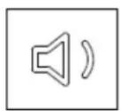
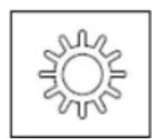
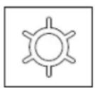
The control buttons provide the following functions (from right to left).
| Feature Description | |
| Brightness - | Decrease brightness |
| Brightness + | Increase brightness |
| Volume - | Decrease speaker volume |
| Volume + | Increase speaker volume |
| Power Power on/off the system | |
| Key Lock | To Lock, press “Brightness +” and “Brightness -” buttonstogether for 3 seconds. To unlock, perform the same procedurefor another 3 seconds. |
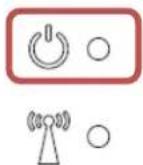
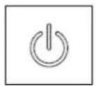
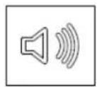
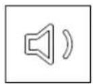
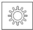
The I-Series has a Power LED indicating the state of the touchcomputer. The table below shows LED state and corresponding color.
| LED Color to Observer State | |
| Off No input power — Off mode | |
| Red Input power present — | Off mode or hibernation |
| Orange Input power present | — Standby |
| Green Input power present — | Power On |
L.E.D. Functionality – Wireless LAN LED
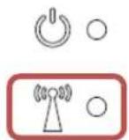

The I-Series has a Wireless LAN LED indicating the wireless connection of the touchcomputer. The table below shows Wireless LAN LED state and corresponding color.
| Wireless State Wireless LED Status | |
| ON | Blue |
| OFF | N/A |
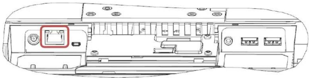
L.E.D. Functionality – Ethernet LED (i2 product shown)
natural_image
Technical line drawing of a device rear panel with internal components and a highlighted ports (no text or symbols)| LAN Speed State LAN LED Status | |
| 10Mbps | No |
| 100Mbps | Orange |
| 1Gbps | Green |
| Activity State ACT LED Status | |
| No Link No Color | |
| Linked Solid (Green Color) | |
| Data Activity Blinking (Green Color) | |
Color Color Color
Using the Input/output Panel (i2 product shown)
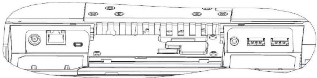
To access the input/output (I/O) ports, remove the cable cover at the bottom of the unit. Two security screws need to be removed before accessing the I/O ports.
natural_image
Technical line drawing of a device rear panel with internal components and connectors (no text or symbols)Note: As a safety precaution, always leave the cable cover door attached when the system is powered on.
Setting Up the Operating System
If configured with an operating system, the initial setup of the operating system takes approximately 5-10 minutes. Additional time may be needed depending on touchcomputer hardware configurations and connected devices.
To set up the Microsoft ^® Windows ^® Operating System for the touchcomputer, turn on the
touchcomputer by pressing the power button, and then follow the on-screen instructions.
Injecting a new language
Windows 7 only allows the use of only one language at one time. So you have to use the Elo language injection feature to modify your language preference. English is set as the default language, but you can change the language to suit your preferences.
- Power off your system completely.
- Power on your system.
- After the Elo splash screen (shown below), press “↑” or “↓” repeatedly to pause on Windows Boot Manager.

- Select either Restore OS 32bit or Restore OS 64bit depending on your OS environment.
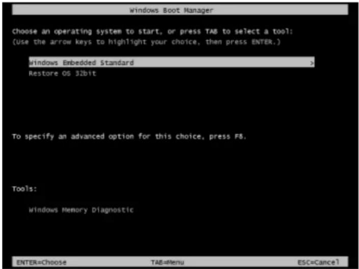
- The following User Interface (UI) will be presented:
![Elo OS Recovery Solution (32-bit) Actions Restore OS Capture OS Console Inject Language (Win 7 only) Exit Status Welcome to the Elo OS Recovery Solution! Please select one of the following actions: - Press [Restore OS] to apply an existing OS image to the device. - Press [Capture OS] to create an image of your current OS. © 2012 BSQUARE Corporation. All rights reserved. v4.0.00.0713](/content/2026/05/860844/images/79ed6af7816d9cb5d7a961244a029396764cc82f0a8d873c307669f9d0a088f2.jpg)
- Select Inject Language and the following UI will be presented.
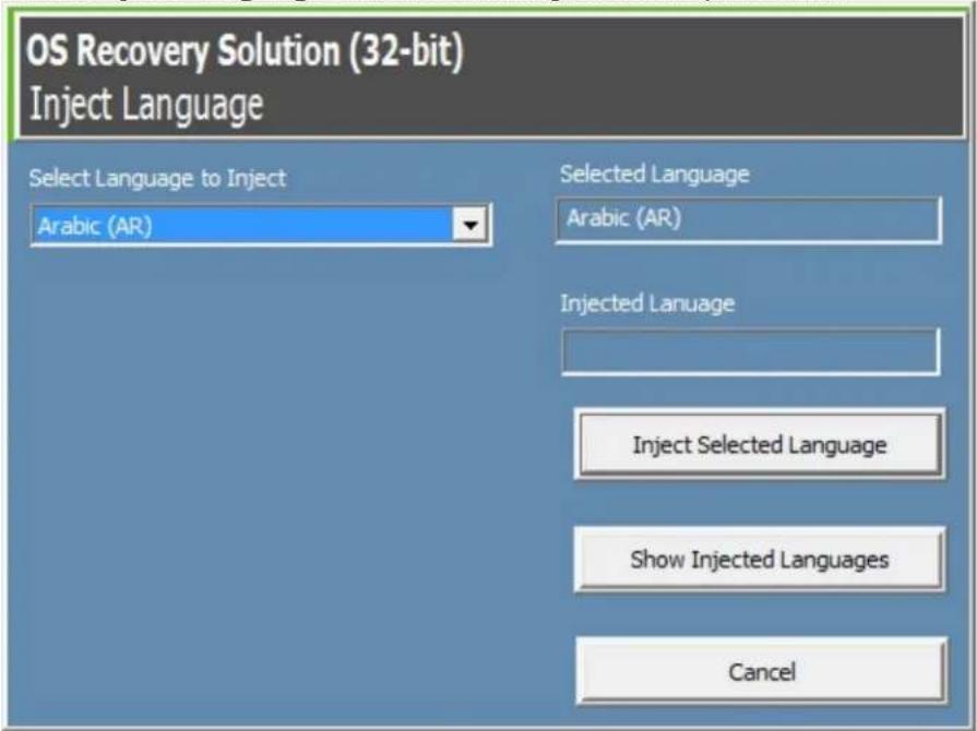
- Click the drop-down list and select the preference language.
- Click Inject Selected Language
- While the injecting process is performing, DO NOT use your keyboard or mouse during this time. It may cause an error in the language injection process.
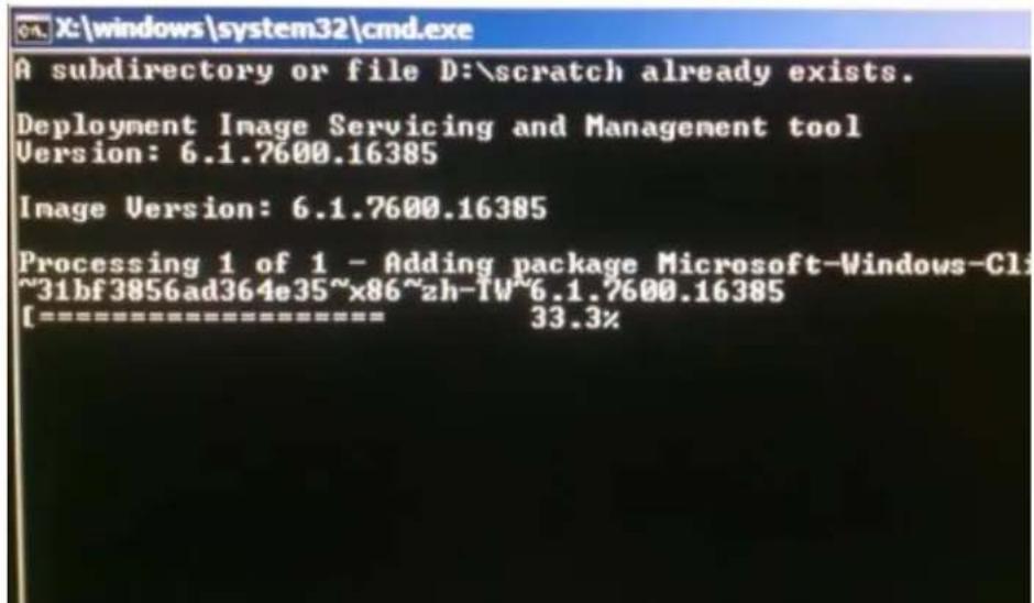
- After the language package is installed correctly, press any key to exit the window.
- You should see the new injected language in both "Selected Language" and "Injected Language".
- Click Cancel → Exit. The system will reboot and new language UI should be presented when the system enters the Desktop.
Creating the Recovery Flash Drive
All Windows 7 and Windows 10 touchcomputers come with the built-in Elo Restore Utility on the Windows Desktop. The utility is able to create a recovery flash drive based on the operating system you purchased. Please create your recovery flash drive immediately. In the event the HDD/SSD recovery partition is accidentally deleted or becomes inaccessible, you will need to use the recovery flash drive to recover your system.
The following procedures demonstrate how to use the utility to create a recovery flash drive.
-
Right-click the EloRestoreUtility icon on the Desktop and select "Run as administrator".
-
Click "Start" button to begin the process.
![Elo Restore Utility Status: Press [Start] Button to begin ... Message: Set default Operating System Start Exit](/content/2026/05/860844/images/716466eb9c3b72918087c0f64026185f6f250236f2fe991bccebf2a5663545c0.jpg)
- Once completed, you shall see a pop-up window to ask to insert a blank flash drive to any of available USB ports on your system.
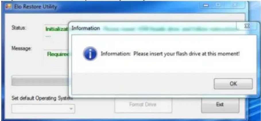
- After the flash drive is inserted, you shall see a window as shown below. Click "Format Drive" to continue the process. PLEASE NOTE THAT ALL DATA WILL BE LOST DURING THIS PROCESS.
![Elo Restore Utility Status: Found Drive - D:\ Message: Press [Format Drive] Button to start format process ... Set default Operating System Format Drive Exit](/content/2026/05/860844/images/fd0d0bc68b496e4fb83b436edde9fed053211794edd032267c91ccce51943493.jpg)
- Click "Create Restore Media" to proceed. This step will take 10-20 minutes depending on your system configurations and flash drive performance.
![Elo Restore Utility Status: Creating directory structures ... Message: Creation directories success. please press [Create Restore Media] to start restore media creation ... Set default Operating System Create Restore Media Exit](/content/2026/05/860844/images/8ea26511cbb65a7fc1138bb024bfe924e09c5d341781dd292896e00e704e2d10.jpg)
- Once the message shows "Creation Restore Media success...", please remove the flash drive and click "Exit" to exit the program.
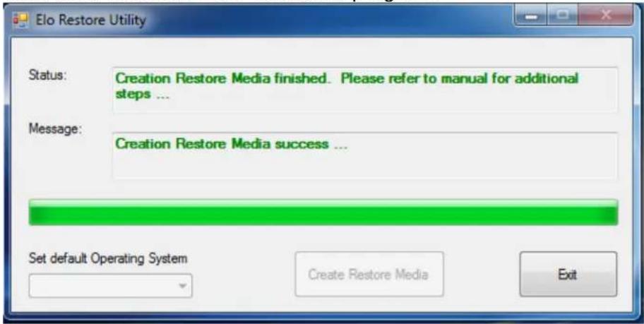
-
In case the system is crashed and you have to use the recovery flash drive, reboot the system and press F11 several times to enter Device Boot Menu. Then, choose boot from flash drive.
-
When the following UI is presented, click "Install Recovery Solution" button.
![Elo OS Recovery Solution (64-bit) Actions Install Recovery Solution Capture OS Console Inject Language (Win 7 only) Exit Status Welcome to the Elo OS Recovery Solution! If you previously captured an OS image file (*.wim), press [Install Recovery Solution]. Otherwise, press [Capture OS] to create an image of your current operating system. © 2012 BSQUARE Corporation. All rights reserved. v4.0.01.0713](/content/2026/05/860844/images/a8c280937bc85185838c8558428d0d9c922a5891dcbcc53c86f9496c1b9c979d.jpg)
- Follow the on-screen instructions to complete the installation process and then exit the program.
Note: All data is deleted during the recovery process. The user must back up files when necessary. Elo Touch Solutions does not accept liability for lost data or software.
Note: The end user must adhere to Microsoft's Licensing Agreement
If for any reason the touchcomputer's operating system needs to be recovered TO FACTORY SETTINGS, you can recover your system by following procedures below. PLEASE NOTE THAT ALL CUSTOMER SETTINGS AND DATA WILL BE LOST DURING THIS PROCESS.
Please be sure to completely backup all of your data, settings, and customer-installed software before proceeding.
- Power off your system completely.
- Power on your system.
- After the Elo splash screen (shown below), press “↑” or “↓” repeatedly to pause on Windows Boot Manager.

natural_image
Blue abstract background with light streaks and a central logo featuring the word 'ēlo' (no additional text or symbols)- Select either Restore OS 32bit or Restore OS 64bit depending on your OS environment.
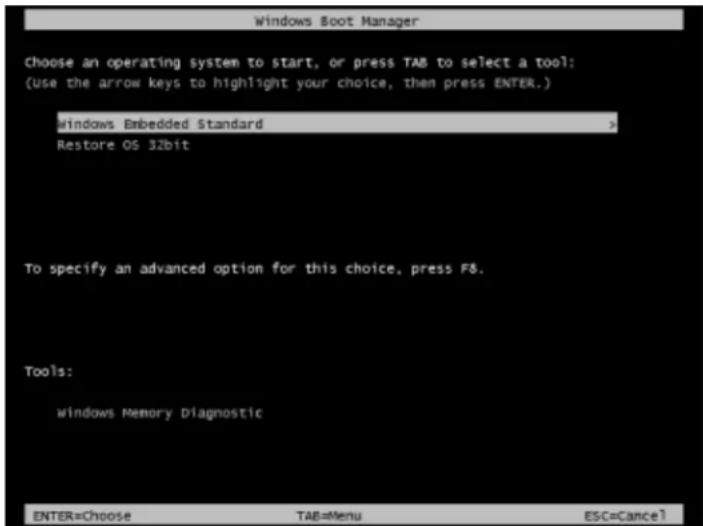
- The following User Interface (UI) will be presented:
![Elo OS Recovery Solution (32-bit) Actions Restore OS Capture OS Console Inject Language (Win 7 only) Exit Status Welcome to the Elo OS Recovery Solution! Please select one of the following actions: - Press [Restore OS] to apply an existing OS image to the device. - Press [Capture OS] to create an image of your current OS. © 2012 BSQUARE Corporation. All rights reserved. v4.0.00.0713](/content/2026/05/860844/images/6aff61c3b3a38f429a41e44b8a9576abd60cd293764c18a1eb48d69c0481be0f.jpg)
- Select Restore OS. System will test your hardware automatically. Once the process completes, click Start button to perform the system recovery function.
![OS Recovery Solution (32-bit) Restore OS Close Recovery Status Ready to Restore OS Current Progress: Overall Progress: Time Elapsed: Start Information This utility will restore the operating system. Please verify the Recovery OS Image file and press [Start] to restore the OS or press [Exit] to return to the main screen: OS Image File: aa32_boot.wim OS Family: Windows 7 WARNING! All data on the OS partition will be lost. © 2012 BSQUARE Corporation. All rights reserved. v3.1.00.0312](/content/2026/05/860844/images/a58e51810b05ffb566cfee6b2081944b66431dde1ecd80e12cef603095af11d7.jpg)
- The following process will reformat the primary hard drive. Please back up your data before performing the recovery process.
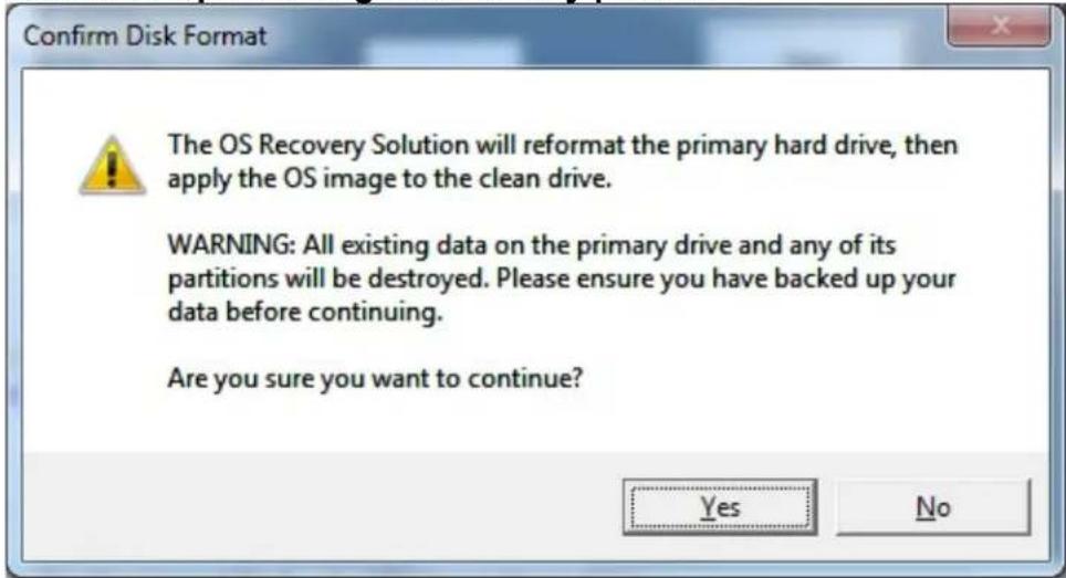
- Once completed, click the Close button. The system will return to the main menu of the Elo Recovery Solution. Then click the Exit button to restart your system.
NOTE: All data is deleted during the recovery process. The user must back up files when necessary. Elo Touch Solutions does not accept liability for lost data or software.
NOTE: The end user must adhere to Microsoft's Licensing Agreement.
Chapter 4: Options and Upgrades
Optional Peripherals Kits
The following optional accessories have been qualified with this system and are available for purchase from Elo. Shown in parenthesis are the Elo orderable part number.
• Magnetic Stripe Reader Kit (E001002)
-MSR with USB interface for all I-Series configurations.
• Near Field Communication Kit (E001004)
-NFC reader with USB interface for all I-Series configurations.
- Barcode Reader Kit (E093433)
-The Barcode Reader Kit is designed with USB interface for all I-Series configurations.
• I-Series 15.6" Stand Kit (E044162)
• I-Series 21.5" Stand Kit (E044356)
• I-Series Wall Mount Kit (E143088)
• I-Series Floor Stand Kit (E048069)
• I-Series Shelf Mount Kit (E043382)
• I-Series GPIO Cable for I-Series (E211544)
• Elo USB Expansion Module (E990645)
Magnetic Stripe Reader Kit (E001002)
You can add a magnetic stripe reader (MSR) to the I-Series in any of the three mounting locations located on the display head bottom, left, and right. Software application and drivers can be found in the following directory or on www.elotouch.com
C:\EloTouchSolutions\Peripherals
The MSR is a USB 2.0 device that reads all three data stripes on standard credit cards or driver's licenses conforming to ISO/ANSI standards. The MSR has foreign language capability. The credit card is read by sliding the credit card forward or backward through the MSR, stripe side toward the display. The MSR is powered from the USB port; no external power is needed.
The MSR specifications are shown in below table.
| Feature Spec Description | |
| Swipe Speed 4~60 ips (10.1~152.4 cm/sec), Bi-direction | |
| Card Width 0.025 ~0.035 inches | |
| Number of Tracks 3 Tracks | |
| Encryption | Triple DES encryption Device & Host Authentication Tokenization |
| Power supply 5.0VDC +/- 0.25V | |
| Power consumption < 2.0 W | |
| Current draw < 40 mA | |
| Current draw - Suspend mode | < 500 uA |
| Interface type Compatible with USB, HID specification | |
| Encrypts security Level 2 | |
| Operating temperature | -20°C to 80°C |
| Encoded data compliance | ANSI/ISO/AAMVA standards |
| Reliability | >1000K times swipes |
MSR allocation on I-Series
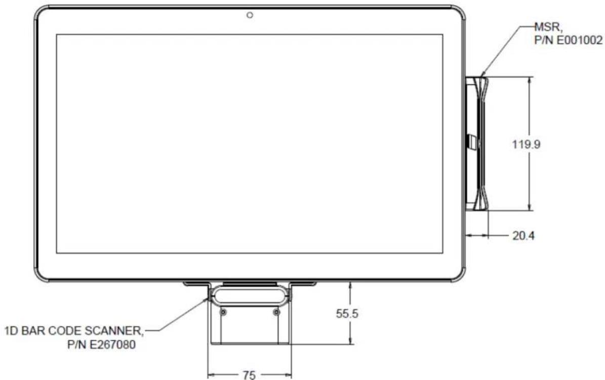
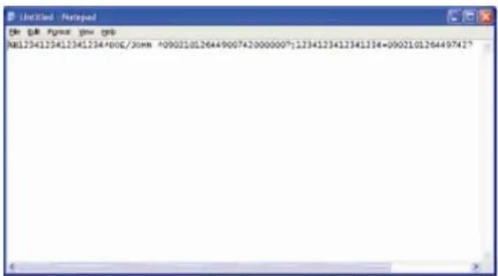
Testing the MSR
Testing in USB MSR Keyboard (KB) Emulation Mode
- Open the Notepad application (click Start > Accessories > Notepad).
- Slide the card through the MSR and verify that the data is displayed in the application window.
Near Field Communication Kit (E001004)
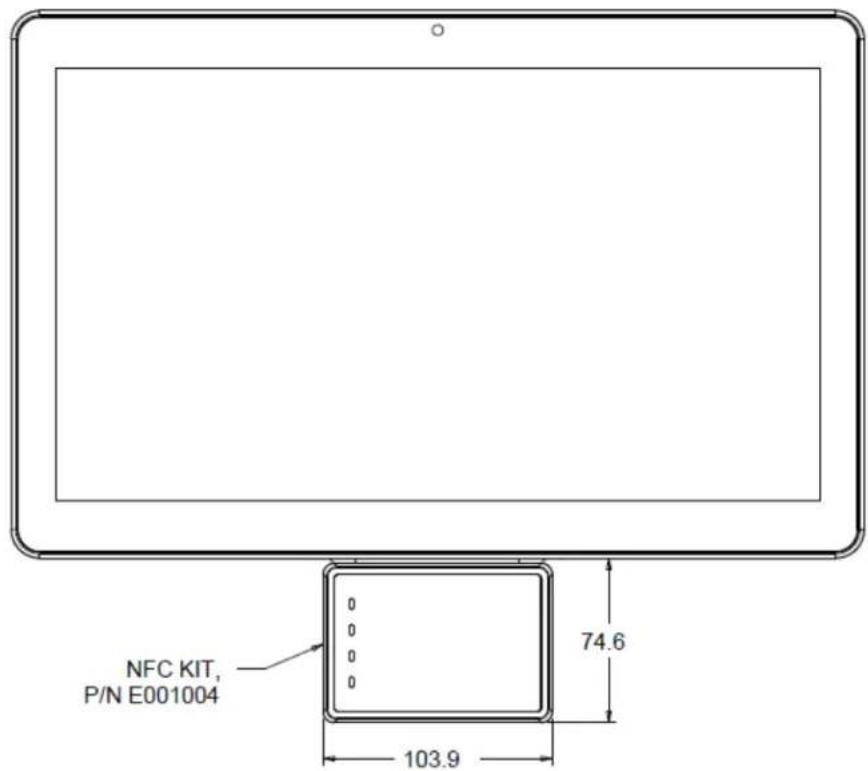
You can add a NFC Kit to the I-Series in any of the three mounting locations located on the display head bottom, left, and right of the touchcomputer
The NFC Kit is a USB 2.0 device and compatible design for I-Series all configurations. The NFC Kit is powered by the USB port; no external power is needed.
The NFC Kit specifications are shown in below table.
| Feature Spec Description | |
| Standards | ISO 14443 TYPE A and B compliantISO 18092 compliant |
| Encryption | Encrypted card data (AES or Triple DES)DUKPT key management with more than 2M keys (model selectable)Authentication with RSA 2048 bit key |
| Payment applications | American Express ExpressPayDiscover ZIPMasterCard PayPass/MCHIPVisa MSD/qVSDCGoogle wallet (optional)Apple PayISIS wallet |
| Contact smart card | Contactless communication at 13.56MHzSupports 2-SAM or 4-SAM board (optional) |
| Antennas | Build-in direct matching antennaRemote 50 ohm matching antenna (optional) |
| Interface type | USB2.0 compliant / HID supportStandard RS-232 signal level |
| Power supply 5.0VDC +/- 0.25V | |
| Power consumption | < 330mA (idle mode)< 430mA (operation mode) |
| Temperature | -20°C to 70°C (Operating)-30°C to 70°C (Storage) |
| Humidity | 10 to 85% (Operating)10 to 90% (Storage) |
NFC KIT allocation on I-Series
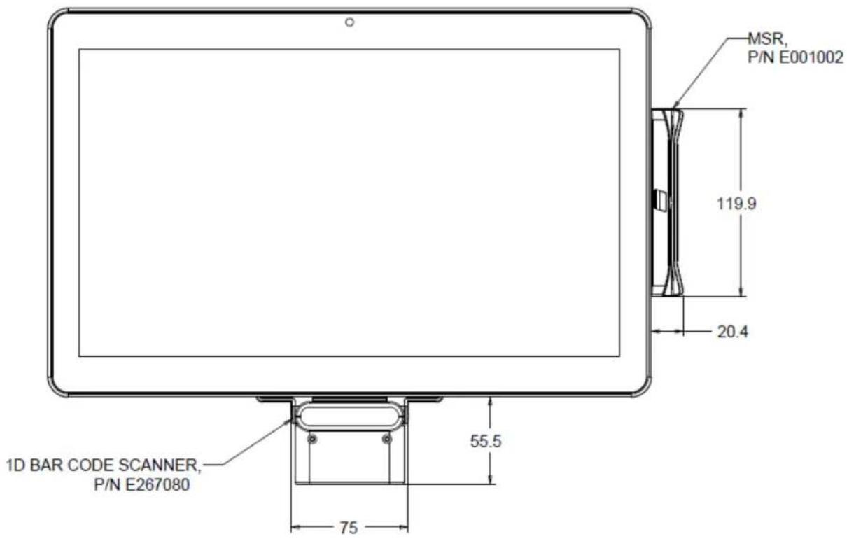
You can optionally add a barcode reader (BCR) Kit to the I-Series in any of the three mounting locations located on the display head bottom, left, and right of the touchcomputer
The barcode reader peripheral shall consist of a mechanical housing, which encloses a barcode reader electrical module. The barcode reader peripheral shall have a USB connection to interface with the I-Series system.
| Feature Spec Description | |
| Light Source 660nm visible LED | |
| Optical sensor 2500 pixels Toshiba CCD sensor | |
| Resolution 3 mil | |
| Depth of Field 35 – 320mm | |
| PCS 30% or more | |
| Interface type USB HID / RS-232 (TTL) / KBW | |
| Voltage + 5V DC ± 5% | |
| Power 120mA @ 5VDC (typ.) | |
| Standby currents 20 ~ 30 mA | |
| Scanning Speed Up to 270 scans/sec | |
| Operating temperature | 0 °C to 55 °C |
| Storage temperature | -20 °C to 60 °C |
| Humidity | 10% ~90% RH (non-condensing) |
| Ambient Light | Works in any lighting conditions, from 0 to 10,000 lux |
BCR allocation on I-Series
You can add a 15.6" Stand Kit to the I-Series to turn the device into a desktop setup. The maximum tilt angle is 70^ from vertical position.
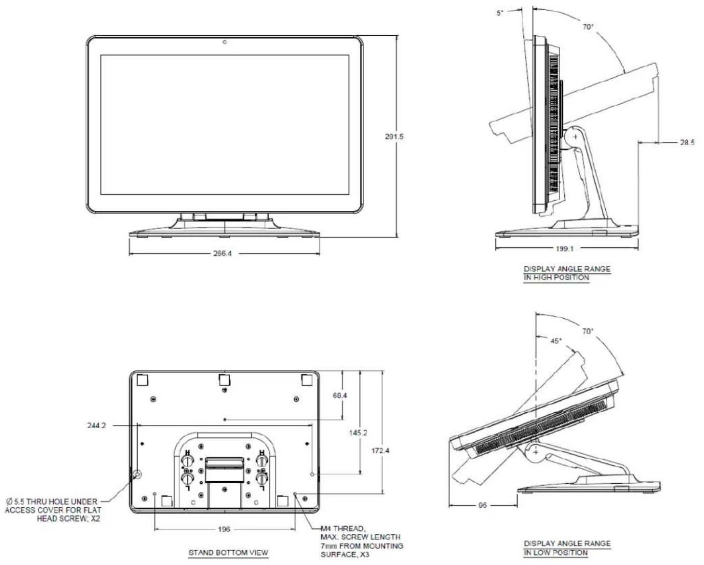
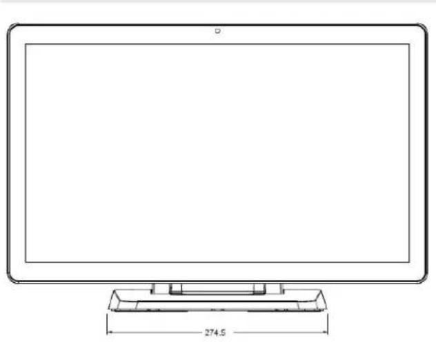
I-Series 21.5" Stand Kit (E044356)
You can add a 21.5" Stand Kit to the I-Series device to turn the system into a desktop setup. The maximum tilt angle is 70^ from vertical position.
natural_image
Line drawing of a flat-screen monitor with a small tray base and dimension label (274.5) at the base (no text or symbols on the device itself)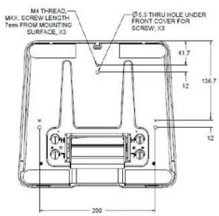
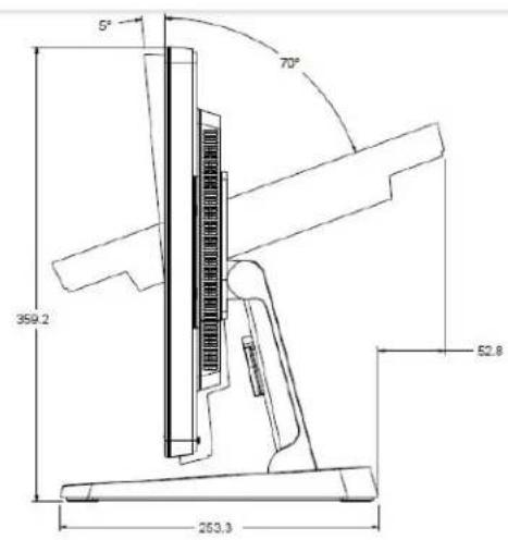
DISPLAY ANGLE RANGE IN HIGH POSITION
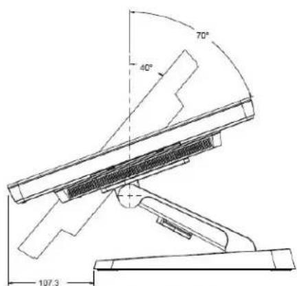
DISPLAY ANGLE RANGE IN LOW POSITION
I-Series Wall Mount Kit (E143088)
You can add a Wall Mount Kit to the I-Series device onto the wall. Basic installation steps show as below.
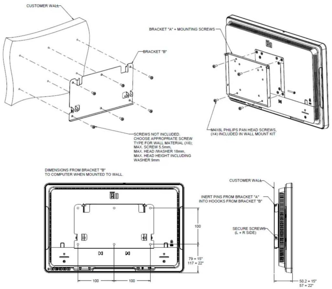
-SCREWS NOT INCLUDED.
CHOOSE APPROPRIATE SCREW
TYPE FOR WALL MATERIAL (X6);
MAX. SCREW 5.5mm,
MAX. HEAD /WASHER 18mm,
MAX. HEAD HEIGHT INCLUDING
WASHER 9mm
-M4X6L PHILIPS PAN HEAD SCREWS, (X4) INCLUDED IN WALL MOUNT KIT
Chapter 5: Technical Support
If you are experiencing trouble with your I-Series, refer to the following suggestions. If the problem persists, please contact your local dealer or contact Elo Customer Service.
Trouble Shooting for Common Problems
| Problem Troubleshooting | |
| No Power(The I-Series unit can’t power on) | 1. Check that the AC/DC power adapter is properly connected.2. Verify the AC power source is functioning.3. Make sure the power button is not broken |
| No Display(Display is black) | 1. If the Power Status LED is orange/red, the I-Series may be in SLEEP/HIBERNATE mode. Press the power button to see if the display comes back.2. Internal cable or electrical part damage. Check another cable or component is cracked or burned. |
| No Bootable Device Found | 1. Confirm the product has loaded the OS.2. Storage device damage. Try to swap with another new blank drive. |
| Abnormal/No Touch function | 1. Check the touch device presents in Windows Device Manager.2. Power off the system and power on again.3. Make sure there is no damage on the touch screen |
Technical Assistance
Visit http://www.elotouch.com/Support/TechnicalSupport/default.asp for technical support.
Refer to the last page of this user manual for Elo contact information worldwide.
Chapter 6: Safety & Maintenance
Safety
To avoid risk of electric shock, follow all safety notices and do not disassemble the Elo I-Series. The Elo I-Series is not user-serviceable.
Do not block or insert anything into any of the ventilation slots.
The Elo I-Series is equipped with an AC/DC power adapter. Do not use a damaged AC/DC power adapter. Use only the AC/DC power adapter supplied by Elo for the I-Series. Use of an unauthorized AC/DC power adapter may invalidate your warranty.
Ensure that the system is maintained and runs within the specified environmental conditions listed below.
Environmental conditions for operating and storage
Temperature:
| Operating | 0°C to 35°C |
| Storage | -30°C to 60°C |
Humidity (non-condensing):
| Operating | 20% to 80% |
Storage
5% to 95%
Altitude:
| Operating | 0 to 3,048 m |
Storage
0 to 12,192 m
The following tips will help maintain optimal performance of your Elo I-Series:
- Disconnect the power cable before cleaning.
- To clean the I-Series (except touchscreen), use soft cotton or microfiber cloth lightly dampened with a mild detergent.
- It is important that your unit remains dry. Do not get liquids on or inside the unit. In the event that liquid does get inside, have a qualified service technician inspect the unit before you power it on again.
- Do not wipe the screen with a cloth or sponge that could scratch the surface.
- When cleaning the touchscreen, use window or glass cleaner applied to a clean cloth. Never apply the cleaner directly on the touchscreen or Elo I-Series. Do not use alcohol (methyl, ethyl or isopropyl), thinner, benzene, or other abrasive cleaners.
Waste Electrical & Electronic Equipment
This product should not be disposed of with household waste. It should be deposited at a facility that enables recovery and recycling. Ensure that product is disposed at the end of its useful life according to local laws and regulations.
Elo has put in place recycling arrangements in certain parts of the world. For information on how you can access these arrangements, please visit http://www.elotouch.com/AboutElo/ewaste-program/.
UL Directive
The I-Series touchcomputer has a lithium battery included on the motherboard. There is a risk of explosion if battery is replaced by an incorrect type. Please dispose of used batteries according to the region instructions.
Warning
- It is important that your touchcomputer remains dry. Do not pour liquid into or onto your touchcomputer. If your touchcomputer becomes wet, do not attempt to repair it yourself. Contact Elo Customer Service for instructions.
- This is a class A product. In a domestic environment this product may cause radio interference in which case the user may be required to take adequate measures.
Chapter 7: Regulatory Information
I. Electrical Safety Information
Compliance is required with respect to the voltage, frequency, and current requirements indicated on the manufacturer label. Connection to a different power source than those specified herein will likely result in improper operation, damage to the equipment or pose a fire hazard if the limitations are not followed.
There are no operator serviceable parts inside this equipment. There are hazardous voltages generated by this equipment which constitute a safety hazard. Service should be provided only by a qualified service technician.
Contact a qualified electrician or the manufacturer if there are questions about the installation prior to connecting the equipment to mains power.
II. Emissions and Immunity Information
Notice to Users in the United States:
This device complies with part 15 of the FCC Rules. Operation is subject to the following two conditions: (1) This device may not cause harmful interference, and (2) this device must accept any interference received, including interference that may cause undesired operation.
Note: This equipment has been tested and found to comply with the limits for a Class A/Class B digital device, pursuant to Part 15 of FCC Rules. These limits are designed to provide reasonable protection against harmful interference in a residential installation. This equipment generates, uses, and can radiate radio frequency energy and, if not installed and used in accordance with the instructions, may cause harmful interference to radio communications. However, there is no guarantee that interference will not occur in a particular installation. If this equipment does cause harmful interference to radio or television reception, which can be determined by turning the equipment off and on, the user is encouraged to try to correct the interference by one or more of the following measures:
-Reorient or relocate the receiving antenna.
-Increase the separation between the equipment and receiver.
-Connect the equipment to an outlet on a circuit different from that to which the receiver is connected.
-Consult the dealer or an experienced radio/TV technician for help.
Caution: Any changes or modifications not expressly approved by the party responsible for
compliance to this equipment would void the user's authority to operate this device.
Canada Compliance Statement:
This Class A/Class B digital apparatus complies with Canadian ICES-003.
This device complies with Industry Canada license-exempt RSS standard(s). Operation is subject to the following two conditions: (1) this device may not cause interference, and (2) this device must accept any interference, including interference that may cause undesired operation of the device.
Notice to Users in Canada:
This equipment complies with the Class A/Class B limits for radio noise emissions from digital apparatus as established by the Radio Interference Regulations of Industrial Canada.
Notice to Users in the European Union:
Use only the provided power cords and interconnecting cabling provided with the equipment. Substitution of provided cords and cabling may compromise electrical safety or CE Mark Certification for emissions or immunity as required by the following standards:
This Information Technology Equipment (ITE) is required to have a CE Mark on the Manufacturers label which means that the equipment has been tested to the following
Directives and Standards: This equipment has been tested to the requirements for the CE Mark as required by EMC Directive 2004/108/EC as indicated in European Standard EN 55022 Class A/Class B and the Low Voltage Directive 2006/95/EC as indicated in European Standard EN 60950.
General Information to all Users:
This equipment generates, uses, and can radiate radio frequency energy. If not installed and used according to this manual the equipment may cause interference with radio and television communications. There is, however, no guarantee that interference will not occur in any particular installation due to site-specific factors.
- In order to meet emission and immunity requirements, the user must observe the following:
a. Use only the provided I/O cables to connect this digital device with any computer.
b. To ensure compliance, use only the provided manufacturers approved line cord.
c. The user is cautioned that changes or modifications to the equipment not expressly approved by the party responsible for compliance could void the user's authority to operate the equipment.
- If this equipment appears to cause interference with radio or television reception, or any other device:
a. Verify an emission source by turning the equipment off and on. If you determine that this equipment is causing the interference, try to correct the interference by using one or more of the following measures:
I. Move the digital device away from the affected receiver.
II. Reposition (turn) the digital device with respect to the affected receiver.
III. Reorient the affected receiver's antenna.
IV. Plug the digital device into a different AC outlet so the digital device and the receiver are on different branch circuits.
V. Disconnect and remove any I/O cables that the digital device does not use. (Unterminated I/O cables are a potential source of high RF emission levels.)
VI. Plug the digital device into only a grounded outlet receptacle. Do not use AC adapter plugs. (Removing or cutting the line cord ground may increase RF emission levels and may also present a lethal shock hazard to the user.)
CE Radiation Exposure Statement:
This equipment complies with CE radiation exposure limits set forth for an uncontrolled environment. This equipment should be installed and operated with minimum distance 20cm between the radiator & your body.
If you need additional help, consult your dealer, manufacturer, or an experienced radio or television technician.
III. EC R&TTE Directive
This equipment conforms to all the essential requirements of Directive 1999/5/EC. The conformity assessment procedure referred to in Article 10 and detailed in Annex [IV] of Directive 1999/5/EC has been with the involvement of the following notified body:
Identification mark: 0700 (Notified body number)
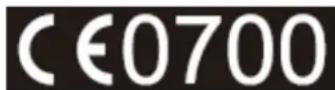
The relevant technical documentation is held at:
Elo Touch Solutions, Inc.
USA
IV. Agency Certifications
The following certifications and marks have been issued or declared for the I-Series:
- Europe Union CE
- United States FCC
- United States and Canada UL
- TUV
- CB
- Japan VCCI
- Energy Star
V. China RoHS
In accordance to Chinese law (Administration on the Control of Pollution Caused by Electronic Information Products), the section below lists out the name and amount of the toxic and/or hazardous materials that this product may contain.
| Component Name | Toxic or Hazardous Substances and Elements | |||||
| Lead(Pb) | Mercury(Hg) | Cadmium(Cd) | Hexavalent Chromium (Cr6+) | Polybrominated Biphenyls (PBB) | Polybrominated Diphenyl Ethers (PBDE) | |
| Plastic Parts | O | O | O | O | O | |
| Metal Parts | X | O | O | O | O | O |
| Wire and Cable Assembly | X | O | O | O | O | O |
| LCD Panel | X | X | O | O | O | O |
| Touch Screen Panel | X | O | O | O | O | O |
| PCBA | X | O | O | O | O | O |
| Software (CD, etc.) | O | O | O | O | O | |
| O: Indicates that this toxic or hazardous substance contained in all of the homogeneous materials for this component is below the limit requirement in SJ/T11363-2006.X: Indicates that this toxic or hazardous substance contained in at least one of the homogeneous materials used for this component is above the limit requirement in SJ/T11363-2006. For items marked with X, exemptions were taken according to EU RoHS. | ||||||
Explanation of Markings
(1). In accordance with the SJ/T11364-2006 requirement, the electronic information products are marked with the following pollution control logo. The Environment-Friendly Use Period for this product is 10 years. The product will not leak or mutate under normal operating conditions listed below, so that the use of this electronic information product will not result in any severe environmental pollution, any bodily injury, or damage to any assets.
Operating Temperature: 0-35°C / Humidity: 20%-80% (non-condensing).
Storage Temperature: -30\~60 °C / Humidity: 5%\~95% (non-condensing).

(2). It is encouraged and recommended that this product be recycled and reused according to local laws. The product should not be thrown away casually.

Chapter 8: Warranty Information
For warranty information, go to http://www.elotouch.com/Support/warranty.asp
Visit our website for the latest
- Product Information
- Specifications
- Upcoming Events
- Press Releases
- Software Drivers
- Touch Display Newsletter
To find out more about the extensive range of Elo touch solutions, go to www.elotouch.com, or call the office nearest you.
North America
Tel 800-ELO-TOUCH
Tel 1-408-597-8000
Fax 1-408-597-8050
customerservice@elotouch.com
Europe
Tel +32 (0) 16 70 45 00
Fax +32 (0) 16 70 45 49
elosales@elotouch.com
Asia-Pacific
Tel +86 (21) 3329 1385
Fax +86 (21) 3329 1400
www.elotouch.com.cn
Latin America
Tel 786-923-0251
Fax 305-931-0124
www.elotouch.com
© Copyright 2016 Elo Touch Solutions, Inc. All rights reserved.
- USER MANUAL
- Elo Touch Solutions
- Copyright © 2016 Elo Touch Solutions, Inc. All Rights Reserved.
- Disclaimer
- Trademark Acknowledgments
- Table of Contents
- Read this first 5
- Chapter 2: Getting Started....11
- Chapter 3: Operation.... 14
- Chapter 4: Options and Upgrades ...... 26
- Chapter 5: Technical Support.... 34
- Chapter 6: Safety & Maintenance .... 36
- Chapter 7: Regulatory Information.... 39
- ENERGY STAR Support information
- Important safety and handling information
- Protect your data and software:
- Take precautions with plastic bags:
- Chapter 1: Product Overview
- Product Description
- Precautions
- Elo Expansion Module (optional for POS capability) Layout
- • 12V/24V Cash Drawer Power Switch
- • RJ11 Cash Drawer Port
- Chapter 2: Getting Started
- Unpacking the Windows I-Series AiO Interactive Signage
- Rear VESA Mount
- Chapter 3: Operation
- General Information
- Front OSD Control Buttons
- L.E.D. Functionality – Wireless LAN LED
- L.E.D. Functionality – Ethernet LED (i2 product shown)
- Using the Input/output Panel (i2 product shown)
- Setting Up the Operating System
- Injecting a new language
- Creating the Recovery Flash Drive
- Chapter 4: Options and Upgrades
- Optional Peripherals Kits
- Magnetic Stripe Reader Kit (E001002)
- MSR allocation on I-Series
- Testing the MSR
- Testing in USB MSR Keyboard (KB) Emulation Mode
- Near Field Communication Kit (E001004)
- NFC KIT allocation on I-Series
- BCR allocation on I-Series
- I-Series 21.5" Stand Kit (E044356)
- I-Series Wall Mount Kit (E143088)
- Chapter 5: Technical Support
- Technical Assistance
- Chapter 6: Safety & Maintenance
- Safety
- Environmental conditions for operating and storage
- Waste Electrical & Electronic Equipment
- UL Directive
- Warning
- Chapter 7: Regulatory Information
- Electrical Safety Information
- Emissions and Immunity Information
- Canada Compliance Statement:
- Notice to Users in Canada:
- Notice to Users in the European Union:
- General Information to all Users:
- CE Radiation Exposure Statement:
- EC R&TTE Directive
- Agency Certifications
- China RoHS
- Explanation of Markings
- Chapter 8: Warranty Information
Brand : ELO
Model : E222782
Category : Office