
BLK-4 - Coffee machine VIKING - Free user manual and instructions
Find the device manual for free BLK-4 VIKING in PDF.


| Product Type | Telephone Line Status Indicator with LED Strobe/Beacon |
| Brand | Viking |
| Model | BLK-4 |
| Strobe Dimensions | 111 mm diameter x 69 mm (4.38" x 2.75") |
| Control Module Dimensions | 74 mm x 53 mm x 25 mm (2.9" x 2.1" x 1.0") |
| Shipping Weight | 1.5 kg (3.3 lbs) |
| Power Supply | 120V AC to 12V DC adapter (included) |
| Strobe Light Output (Blue Lens) | 116 lumens @ 15VDC |
| Relay Contact Rating | 0.5A @ 125V AC / 1A @ 30V DC |
| Operating Temperature | -26°C to 54°C (-15°F to 130°F) |
| Humidity (Non-EWP) | 5% to 95% non-condensing |
| Humidity (EWP Version) | Up to 100% condensing (IP66 rated) |
| Minimum Loop Current | 15 mA |
| Minimum Ring Voltage | 25V RMS |
| Ringer Equivalence | 0.5 A REN |
| Strobe Flash Patterns | Single, Double, Quad, Flicker Flash |
| Beacon/Strobe Modes | Beacon only, Strobe only, or Beacon/Strobe combined |
| Mounting Options | Flush mount or surface mount with included weatherproof single gang box |
| Warranty | 2-year limited warranty |
| Maintenance | Clean with a soft, dry cloth; avoid moisture ingress in non-EWP units |
| Safety Features | IP66 rating for EWP models; indoor use for standard model |
Frequently Asked Questions - BLK-4 VIKING
User questions about BLK-4 VIKING
0 question about this device. Answer the ones you know or ask your own.
Ask a new question about this device
Download the instructions for your Coffee machine in PDF format for free! Find your manual BLK-4 - VIKING and take your electronic device back in hand. On this page are published all the documents necessary for the use of your device. BLK-4 by VIKING.
USER MANUAL BLK-4 VIKING
Provide LED Strobe / Beacon Visual Indication of Line Status
The BLK-4 provides high visibility indication of analog line status through a high powered 360° LED strobe and/or beacon visual indicator. The BLK-4 is the ideal solution for the hearing impaired and can be used equally well in loud warehouses or factories, where ringing phones can not be heard. Alternatively, the BLK-4 can be used to add emergency notification to pre-existing emergency phones by turning on the strobe light when the emergency phone is in use.
The included control module has a disable input which is ideal for two-button emergency phones, such as Viking's E-1600-20A, allowing "Info" button calls to be placed without activating the relay (turning on the emergency strobe light, camera, etc.) Four DIP switches are provided for turning ring detection on or off, off-hook/loop detection on or off, 12VDC or dry relay contact output and for selecting a ring cadence mode which allows the relay to follow ringing or to remain activated during the off time of standard ring cadence. The control module can be installed on any standard telephone line or analog PABX/KSU station. The strobe can be interfaced to flash on ringing, off-hook or a combination of ringing and off-hook (line in-use).
The BLK-4 is designed for indoor applications. The BLK-
Features
- BLK-4-EWP's control module and strobe light come with Enhanced Weather Protection (EWP), EWP products are designed to meet IP66 Ingress Protection Rating, see DOD# 859
• Durable polycarbonate lens - High output long life LED technology
- Four programmable flash patterns:
- Single Flash - Double Flash
- Quad Flash - Flicker Flash
- 6 programmable beacon and strobe brightness settings
• Immune to shock and vibration - Flush mount or surface mount with weatherproof single gang box (included)
- 3/4" knockouts for connecting conduit, etc.
- Strobe and control module may be installed separately
- Can be configured to signal: ringing, off-hook, a combination of both ringing and off-hook (line in-use), or triggered from a contact closure
- One set of (NO) normally open and (NC) normally closed relay contacts provided
- Selectable ring cadence mode (strobe light will remain flashing between rings)
- Switched 12V DC output (follows relay activation for powering strobe lights, cameras, etc.)
- On/off switches for ring detection and off-hook/loop detection
- Disable input, ideal for use with two-button emergency phones like Viking's E-1600-20A (DOD# 215), will not activate strobe light on "Info" calls
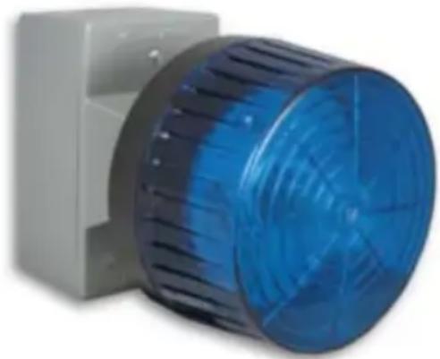
natural_image
Close-up of a blue industrial fan or vent with ventilation grille, mounted on a white base (no text or symbols visible)4-EWP is equipped with Enhanced Weather Protection (EWP) for outdoor installations where the unit is exposed to precipitation or condensation. For more information, see DOD# 859.
The kit includes: (1) control module, (1) SL-2/SL-2-EWP blue LED strobe light, (1) 12V DC power adapter, (16) gel-filled butt connectors and (1) single gang weatherproof mounting box with gaskets and hardware.
Applications
- Ringing Phone or TTY indication for the hearing impaired
- Ringing phone indication in loud warehouses and factories
• Emergency illumination for emergency phones in elevators, campuses, hallways, parking ramps, etc. - Alarm indication for security systems or alarm panels with phone dialers
Specifications
Power: 120V AC to 12V DC adapter provided
Maximum Power Supply Run Length on CAT-5: 1 pair = 125 ft, 2 pair = 225 ft, 3 pair = 325 ft, 4 pair = 475 ft
Maximum SL-2 Wire Run Length on CAT-5: 3 wires = 100 ft, 6 wires = 300 ft
Strobe Dimensions: 111mm diameter x 69mm (4.38" x 2.75")
Control Module Dimensions: 74mm x 53mm x 25mm (2.9" x 2.1" x 1.0")
Shipping Weight: 1.5 kg (3.3 lbs)
Operating Temperature: -26° to 54°C (-15° to 130°F)
Relay Contact Rating: .5A @ 125V AC/1A @ 30V DC
Minimum Loop Current: 15 mA
Minimum Ring Voltage: 25V RMS
Ringer Equivalence: 0.5 A REN
Disable/Info Switch Input: 50mA/80mW maximum
Strobe Flash Rate: 60 flashes per minute (default) see Strobe Flash Patterns page 6
Maximum Strobe Light Output @ 15VDC: Clear lens: 323 lumens, Amber lens: 242 lumens, Blue lens: 116 lumens, Red lens: 66 lumens
Humidity - BLK-4: 5% to 95% non-condensing
Humidity - BLK-4-EWP: up to 100% condensing
Mounting: Fasten to wall, post, etc. with complete surface mounting hardware included
Connections: Color coded wires with gel-filled butt connectors
Wiring
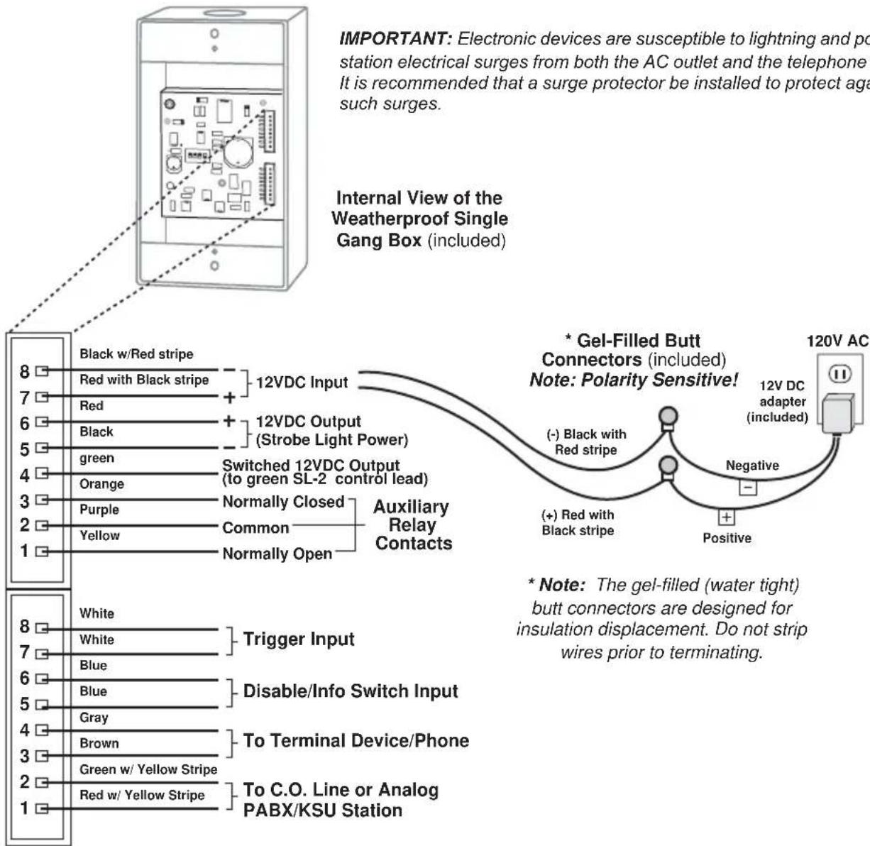
Control Module
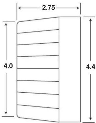
Side View of the Strobe Light (included)
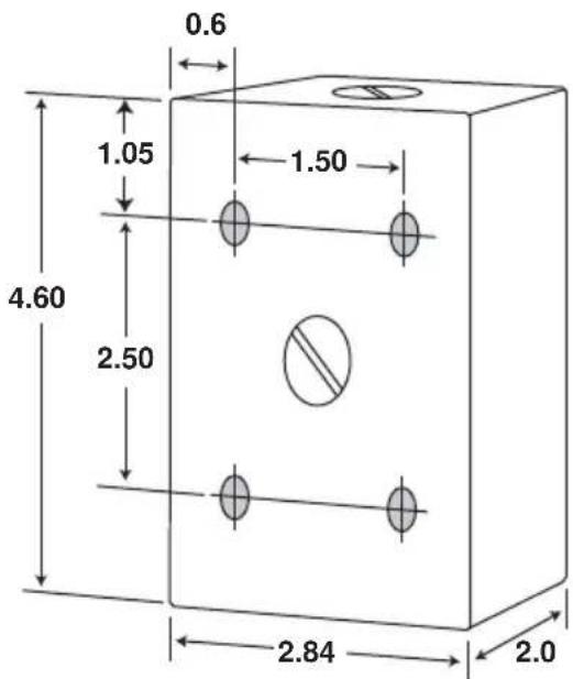
Back View of the Weatherproof Single Gang Box (included)
A. Installing the Strobe Light Using the Included Weatherproof Box
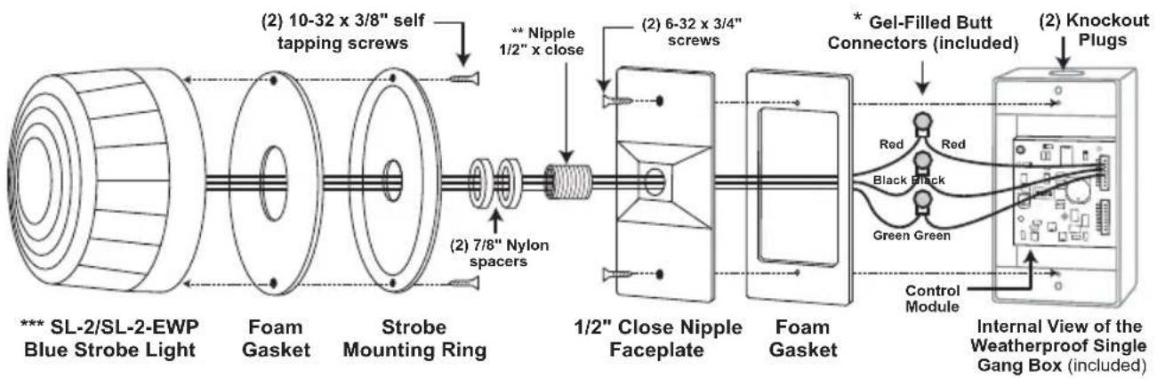
* Note: The gel-filled (water tight) butt connectors are designed for insulation displacement. Do not strip wires prior to terminating.
** Important: First fully tighten the nipple into the faceplate. Next add the (2) nylon spacers, then fasten the strobe mounting ring.
*** Note: For outdoor applications, orient the blue strobe light with the screws at the top and bottom. Use a bead of silicone to fill any gaps or spaces to prevent water from entering the strobe light.
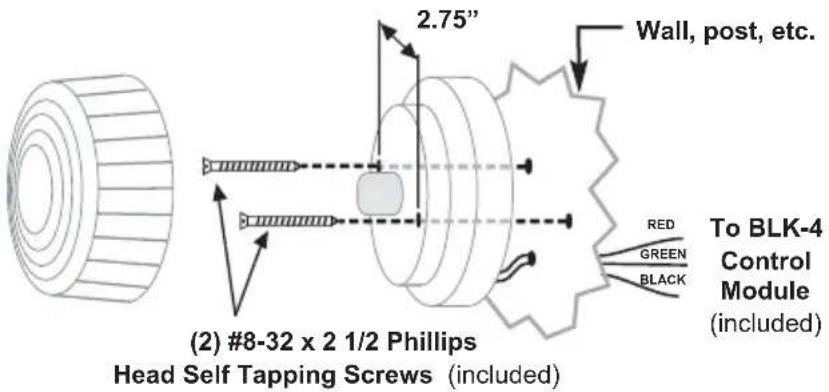
B. Front Mounting Without Weatherproof Box
The BLK-4 Strobe Light Kit may be mounted without using the included weatherproof box. To mount the strobe light from the front, use the diagram shown to the right.
SL-2/SL-2-EWP
Strobe Light
(included)
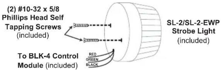
C. Rear Mounting Without Weatherproof Box
To mount the strobe light from the rear, use the diagram shown to the right.
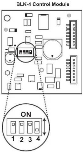
A. DIP Switches
| Switch 1 | Switch 3 | Description |
| ON | OFF | Ring Detection Only (see section B). |
| OFF | ON | Off-Hook/Loop Current Detection Only (see section B). |
| ON | ON | Ring and Off-Hook/Loop Current Detection (see section B). |
| Switch 2 | Ring Cadence Mode (see section C) | |
| ON | Ring Cadence Mode ON - relay remains activated in between rings. | |
| OFF | Ring Cadence Mode OFF - relay is activated only during ringing. | |
| Switch 4 | Auxiliary Relay Contacts | |
| ON Wet (12VDC, 100mA maximum) | ||
| OFF Dry (1 Amp maximum @ 30VDC) | ||
B. Configuring for Ring and/or Loop/Off-Hook Indication
* Note: The gel-filled (water tight) butt connectors are designed for insulation displacement. Do not strip wires prior to terminating.
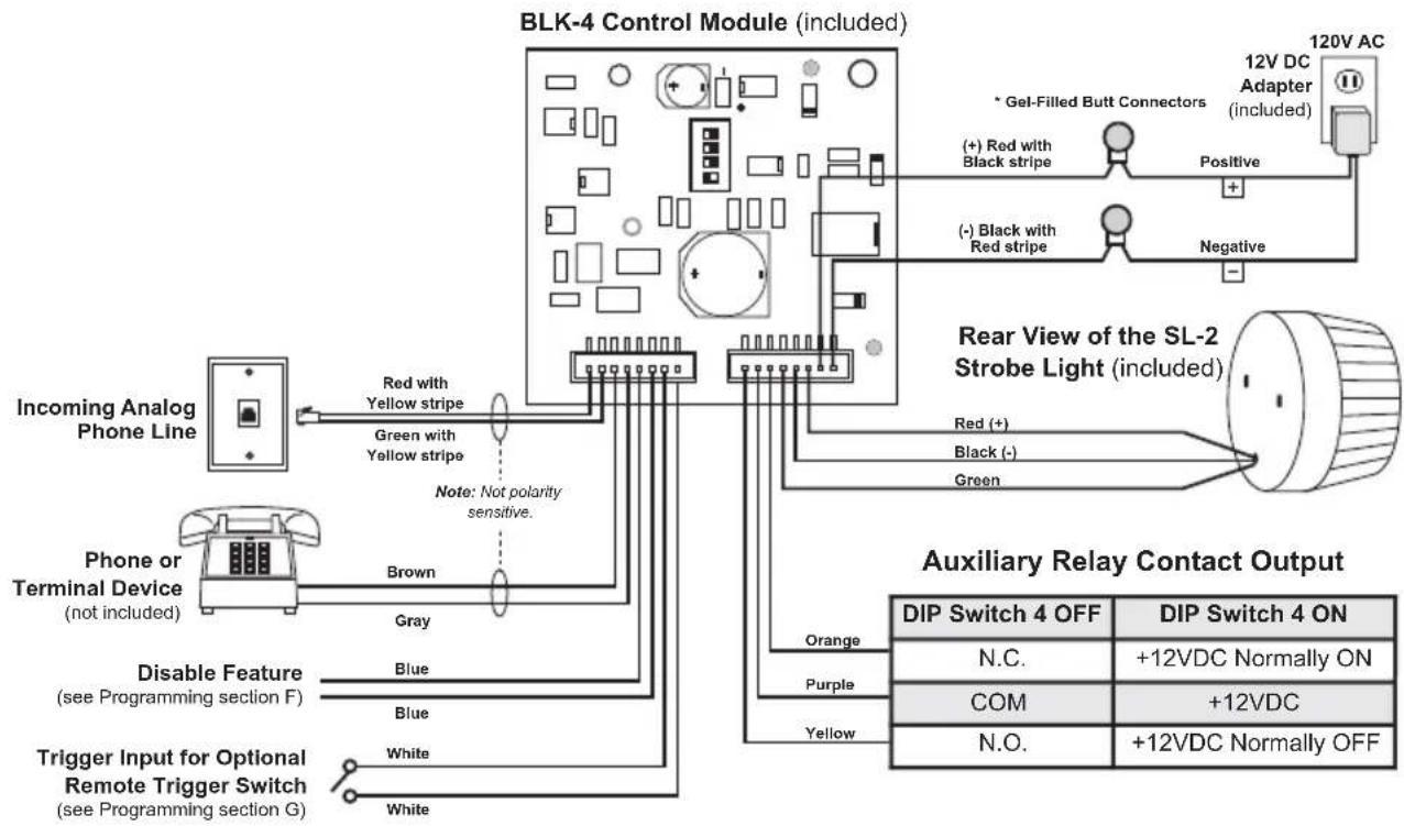
1. Ring Indication Only
Connect the incoming line to the red and green wires with the yellow stripe as shown in the diagram. No phone/terminal device is required. The control module can monitor for ringing any place along the ringing line.
2. Loop/Off-hook Indication Only
The control module must be placed between the phone line and the phone/terminal device to be monitored. Connect the incoming line to the red and green wires with the yellow stripe and connect the phone/terminal device to the brown and gray wires as shown.
3. Both Ring and Loop/Off-hook Indication
If the application requires ring and loop/off-hook indication, the control module must be placed between the phone line and the phone/terminal device to be monitored. Connect the incoming line to the red and green wires with the yellow stripe, connect the phone/terminal device to the brown and gray wires.
C. Ring Cadence Mode
DIP switch 2 is used for switching between different ring detection modes. In the OFF position, the relay and switched 12VDC output will activate only while ring voltage is present and will turn off between rings. In the ON position, the relay and switched 12VDC output will remain on for up to 5.75 seconds after the ringing has stopped. This allows the relay and 12VDC (flashing strobe light) to remain on between rings of a standard ring cadence. Note: To use the Ring Cadence Mode, ring detection MUST be enabled (DIP switch 1 - ON).
D. Auxiliary Relay Contacts
With DIP switch 4 OFF, normally open and normally closed dry relay contacts are available on the orange, purple and yellow wires. The contacts are rated at .5A @ 125VAC/1A @ 30VDC. If contacts are driving an inductive load, place a suppression device at the load to snub high voltage spikes.
With DIP switch 4 ON, wet/switched +12VDC (100mA maximum) will be output on the yellow wire and “-” (GND) on the black wire.
E. Switched 12V DC Output
The switched 12V DC output is a low current, 12-15VDC output that is turned on only while the trigger input is closed or ring/loop detect relay is activated. This switched power output is ideal for triggering the included strobe light or providing 12-15V DC power to any device that draws less than 400mAmps. The positive side is available on the green wire, and the negative side is on the black wire. Once all the line and load connections have been made, plug in the 115 V AC wall adapter, and replace the cover.
F. Disable Feature
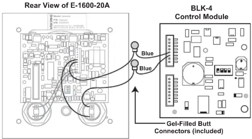
By connecting the Disable/Info Switch input of the BLK-4 control module to the "Info" switch of Viking's E-1600-20A, E-1600-20A-EWP, E-1600-52A or E-1600-52A-EWP Emergency Phone, any outbound call initiated from the "Info" button will not activate the strobe light. This way, only the "Help/Emergency" outbound calls will activate the relay. Cut one of the "Info" switch wires in half and connect each end to the blue wires on the BLK-4 control module as shown in the diagram at the right. Note: This Disable input is NOT polarity sensitive. The "Disable" input can be connected to a switch for remotely disabling/turning off the device (strobe light, camera, etc.) controlled by the BLK-4 control module. For more information, see DOD# 866.
G. Trigger Input
The trigger input is available on the two white wires. The Strobe Light, Auxiliary relay contact and the switched 12 VDC output will be activated for the duration of the contact closure across the two white wires.
The SL-2 can be user programmed as a Beacon only, Strobe only or Beacon/Strobe. The brightness setting can be programmed separately for the Strobe or Beacon and one of 4 different Flash Patterns can be programmed for the Strobe (see Strobe Flash Patterns, section D).
IMPORTANT: The SL-2 is factory default programmed as a steady on beacon with a single flash strobe when activated. The beacon and strobe are set to their brightest settings. All programming should be done prior to connecting to the BLK-4 control module.
A. Accessing the Programming Mode
(Optional, the SL-2 is factory programmed to the Beacon/Strobe Mode and brightest Beacon/Strobe settings).
| Step 1. | Apply 10-15 VDC power to the Red (+) and Black (-) wires. |
| Step 2. | Touch and hold the Green (Control) wire to the Black (-) wire for 3 seconds. The strobe should flash twice. You are now in Programming mode. Note: Once in the programming mode, if a programming command has not been entered for 20 seconds the strobe will flash 3 times indicating the unit has exited programming and returned to the Run Mode. |
B. Programming Desired Features (after accessing Programming Mode above)
Select the Feature: Momentarily touch the Green (Control) wire to the Black (-) wire 1 to 10 times to select which feature to program (see Programming Features List, section C). The strobe should momentarily flash each time the Green (Control) wire has touched the Black (-) wire.
Features 1-3 & 6-10: After selecting Programming Features 1-3 or 6-10, wait 3 seconds and the strobe should flash 2 times indicating that feature has been programmed. You can now exit programming or move on to programming the Beacon or Strobe brightness settings.
Setting Strobe Brightness (factory set to 6/Brightest): After selecting Programming Feature 4 (Strobe Brightness), wait 3 seconds and the strobe should begin flashing in the preprogrammed flash pattern. Touch and hold the Green (Control) wire to the Black (-) wire. The SL-2 will begin flashing the strobe cycling through 6 different brightness settings from lowest to highest. When the SL-2 flashes at the desired brightness level immediately remove the Green wire from the Black. The SL-2 should flash twice indicating the selected brightness level has been set.
Setting Beacon Brightness (Factory set to 6/Brightest): After selecting Programming Feature 5 (Beacon Brightness), wait 3 seconds and the beacon will light at its preprogrammed beacon brightness setting. Touch and hold the Green (Control) wire to the Black (-) wire. The SL-2 will begin stepping through 6 different beacon brightness settings from lowest to highest. When the SL-2 lights at the desired beacon brightness level immediately remove the Green wire from the Black. The SL-2 should flash twice indicating the selected brightness level has been set.
Exiting Programming: To exit programming simply wait 20 seconds from the last programming command and the unit will flash 3 times. This indicates the SL-2 has exited the programming mode and is now in the Run mode. Note: To eliminate waiting 20 seconds, you can also exit programming after the last programming command by touching and holding the Green (Control) wire to the Black (-) for 3 seconds. The strobe will flash 3 times indicating the unit has exited the programming mode and is now in the Run mode.
C. Programming Features List
| Feature # : Description: | |
| 1 Beacon/Strobe (factory default) | |
| 2 Strobe Only | |
| 3 Beacon Only | |
| 4 Strobe Brightness 1-6 (factory default = 6/Brightest setting) | |
| 5 Beacon Brightness 1-6 (factory default = 6/Brightest setting) | |
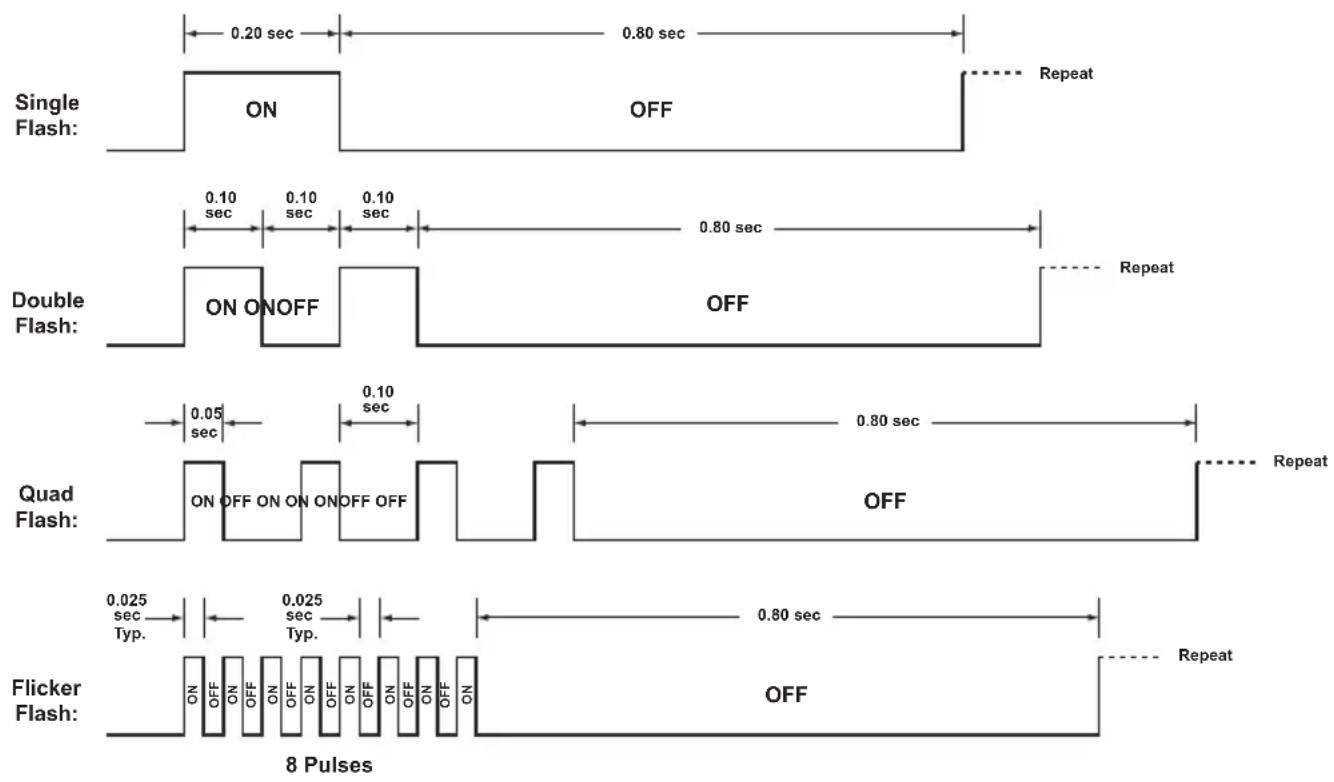
| 6 Single Flash Strobe (factory default) | |
| 7 Double Flash Strobe | |
| 8 Quad Flash Strobe | |
| 9 Flicker Flash Strobe | |
| 10 Reset to Factory Default Settings |
D. Strobe Flash Patterns
Operation
A. Ring Indication (DIP Switch 1 ON)
When the control module detects an incoming ring signal, it activates a set of normally open or normally closed contacts and turns on the 12VDC output for activating the provided strobe light. With the Ring Cadence mode off (DIP switch 2 OFF), the relay will activate and the strobe light will flash only during ringing. With the Ring Cadence mode ON (DIP switch 2 ON), the relay will remain activated and the strobe light will remain flashing between rings.
B. Off-Hook Indication (DIP Switch 3 ON)
When the control module detects an off-hook condition (loop current) on the brown and gray wires, it activates a set of normally open or normally closed contacts and turns on the 12VDC output for activating the provided strobe light. The relay contacts will remain activated and the blue strobe light will flash during the off-hook condition and will stop flashing approximately 3 seconds after the phone/terminal device on the brown and gray wires is back on-hook.
Applications
Mounting the BLK-4 with the E-1600-20A
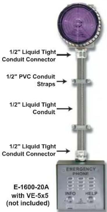
The BLK-4 can be used in conjunction with the E-1600-20A Two-Button Emergency Phone as shown to the far right, however, special installation and mounting is required. Please follow the steps below when using the BLK-4 in conjunction with a surface-mounted E-1600-20A. A VE-5x5 surface-mount box is required, see DOD# 424.
| Step 1. | Drill or use a knockout punch to provide a .875" diameter hole in the top of the VE-5x5. |
| Step 2. | Make all conduit connections. |
| Step 3. | Make all wire connections to the control module. |
| Step 4. | Install the E-1600-20A as explained in its Technical Practice, DOD# 215. |
Warranty
IF YOU HAVE A PROBLEM WITH A VIKING PRODUCT, CONTACT: VIKING TECHNICAL SUPPORT AT (715) 386-8666
Our Technical Support Department is available for assistance Monday 8am - 4pm and Tuesday through Friday 8am - 5pm central time. So that we can give you better service, before you call please:
-
Know the model number, the serial number and what software version you have (see serial label).
-
Have your Technical Practice in front of you.
-
It is best if you are on site.
RETURNING PRODUCT FOR REPAIR
The following procedure is for equipment that needs repair:
- Customer must contact Viking's Technical Support Department at 715-386-8666 to obtain a Return Authorization (RA) number. The customer MUST have a complete description of the problem, with all pertinent information regarding the defect, such as options set, conditions, symptoms, methods to duplicate problem, frequency of failure, etc.
- Packing: Return equipment in original box or in proper packing so that damage will not occur while in transit. Static sensitive equipment such as a circuit board should be in an anti-static bag, sandwiched between foam and individually boxed. All equipment should be wrapped to avoid packing material lodging in or sticking to the equipment. Include ALL parts of the equipment. C.O.D. or freight collect shipments cannot be accepted. Ship cartons prepaid to: Viking Electronics, 1531 Industrial Street, Hudson, WI 54016
- Return shipping address: Be sure to include your return shipping address inside the box. We cannot ship to a PO Box.
- RA number on carton: In large printing, write the R.A. number on the outside of each carton being returned.
RETURNING PRODUCT FOR EXCHANGE
The following procedure is for equipment that has failed out-of-box (within 10 days of purchase):
- Customer must contact Viking's Technical Support at 715-386-8666 to determine possible causes for the problem. The customer MUST be able to step through recommended tests for diagnosis.
- If the Technical Support Product Specialist determines that the equipment is defective based on the customer's input and troubleshooting, a Return Authorization (R.A.) number will be issued. This number is valid for fourteen (14) calendar days from the date of issue.
- After obtaining the R.A. number, return the approved equipment to your distributor, referencing the R.A. number. Your distributor will then replace the Viking product using the same R.A. number.
- The distributor will NOT exchange this product without first obtaining the R.A. number from you. If you haven't followed the steps listed in 1, 2 and 3, be aware that you will have to pay a restocking charge.
TWO YEAR LIMITED WARRANTY
Viking warrants its products to be free from defects in the workmanship or materials, under normal use and service, for a period of two years from the date of purchase from any authorized Viking distributor. If at any time during the warranty period, the product is deemed defective or malfunctions, return the product to Viking Electronics, Inc., 1531 Industrial Street, Hudson, WI., 54016. Customer must contact Viking's Technical Support Department at 715-386-8666 to obtain a Return Authorization (R.A.) number.
This warranty does not cover any damage to the product due to lightning, over voltage, under voltage, accident, misuse, abuse, negligence or any damage caused by use of the product by the purchaser or others. This warranty does not cover non-EWP products that have been exposed to wet or corrosive environments. This warranty does not cover stainless steel surfaces that have not been properly maintained.
NO OTHER WARRANTIES. VIKING MAKES NO WARRANTIES RELATING TO ITS PRODUCTS OTHER THAN AS DESCRIBED ABOVE AND DISCLAIMS ANY EXPRESS OR IMPLIED WARRANTIES OR MERCHANTABILITY OR FITNESS FOR ANY PARTICULAR PURPOSE.
EXCLUSION OF CONSEQUENTIAL DAMAGES. VIKING SHALL NOT, UNDER ANY CIRCUMSTANCES, BE LIABLE TO PURCHASER, OR ANY OTHER PARTY, FOR CONSEQUENTIAL, INCIDENTAL, SPECIAL OR EXEMPLARY DAMAGES ARISING OUT OF OR RELATED TO THE SALE OR USE OF THE PRODUCT SOLD HEREUNDER.
EXCLUSIVE REMEDY AND LIMITATION OF LIABILITYWHETHER IN AN ACTION BASED ON CONTRACT, TORT (INCLUDING NEGLIGENCE OR STRICT LIABILITY) OR ANY OTHER LEGAL THEORY, ANY LIABILITY OF VIKING SHALL BE LIMITED TO REPAIR OR REPLACEMENT OF THE PRODUCT, OR AT VIKING'S OPTION, REFUND OF THE PURCHASE PRICE AS THE EXCLUSIVE REMEDY AND ANY LIABILITY OF VIKING SHALL BE SO LIMITED.
IT IS EXPRESSLY UNDERSTOOD AND AGREED THAT EACH AND EVERY PROVISION OF THIS AGREEMENT WHICH PROVIDES FOR DISCLAIMER OF WARRANTIES, EXCLUSION OF CONSEQUENTIAL DAMAGES, AND EXCLUSIVE REMEDY AND LIMITATION OF LIABILITY, ARE SEVERABLE FROM ANY OTHER PROVISION AND EACH PROVISION IS A SEPARABLE AND INDEPENDENT ELEMENT OF RISK ALLOCATION AND IS INTENDED TO BE ENFORCED AS SUCH.
Product Support: (715) 386-8666
Due to the dynamic nature of the product design, the information contained in this document is subject to change without notice. Viking Electronics, and its affiliates and/or subsidiaries assume no responsibility for errors and omissions contained in this information. Revisions of this document or new editions of it may be issued to incorporate such changes.
- Provide LED Strobe / Beacon Visual Indication of Line Status
- Features
- Applications
- Specifications
- Wiring
- Installing the Strobe Light Using the Included Weatherproof Box
- Front Mounting Without Weatherproof Box
- Rear Mounting Without Weatherproof Box
- DIP Switches
- Configuring for Ring and/or Loop/Off-Hook Indication
- Ring Indication Only
- Loop/Off-hook Indication Only
- Both Ring and Loop/Off-hook Indication
- Ring Cadence Mode
- Auxiliary Relay Contacts
- Switched 12V DC Output
- Disable Feature
- Trigger Input
- Accessing the Programming Mode
- Programming Desired Features (after accessing Programming Mode above)
- Programming Features List
- Strobe Flash Patterns
- Operation
- Ring Indication (DIP Switch 1 ON)
- Off-Hook Indication (DIP Switch 3 ON)
- Mounting the BLK-4 with the E-1600-20A
- Warranty
- IF YOU HAVE A PROBLEM WITH A VIKING PRODUCT, CONTACT: VIKING TECHNICAL SUPPORT AT (715) 386-8666
- RETURNING PRODUCT FOR REPAIR
- RETURNING PRODUCT FOR EXCHANGE
- TWO YEAR LIMITED WARRANTY
- Product Support: (715) 386-8666
Brand : VIKING
Model : BLK-4
Category : Coffee machine