
ENVY Curved Pro Curved - Office HP - Free user manual and instructions
Find the device manual for free ENVY Curved Pro Curved HP in PDF.


| Product Type | All-in-One Desktop PC |
| Model | HP ENVY Curved Pro Curved |
| Display | Curved display (specific size not specified) |
| Processor | Intel Core i7-6700T (2.8 GHz) or Intel Core i5-6400T (2.2 GHz) |
| Memory | 8 GB SODIMM DDR4-2133 (max 8 GB, 2 slots) |
| Storage | 2 TB 5400 rpm HDD or 1 TB 7200 rpm HDD; optional 128 GB or 256 GB PCIe SSD |
| Wireless | Intel 802.11ac (2×2) WLAN + Bluetooth 4.0 |
| Ports | USB 3.0 (1 charging), USB 2.0 (2), HDMI-in, HDMI-out, RJ-45, audio combo jack, memory card reader |
| Webcam | Yes, with IR camera and dual microphones |
| Speakers | Built-in woofer and tweeter pairs |
| Power Supply | 180 W external; input 100–240 V, 50–60 Hz; output 19 V, 9.47 A |
| Dimensions (W × D × H) | 36.6 × 6.6 × 18.4 in (93.0 × 16.8 × 46.7 cm) |
| Weight | Approximately 29.8 lb (13.52 kg) |
| Operating Temperature | 41° to 95°F (5° to 35°C) |
| Non-operating Temperature | -4° to 140°F (-20° to 60°C) |
| Operating Humidity | 10–90% non-condensing |
| Maximum Altitude (operating) | -50 ft to 10,000 ft (-15 m to 3,048 m) |
| Operating System | Windows 10 (preinstalled) |
| Security | Administrator and power-on passwords, TPM, Secure Boot |
| Maintenance | Clean with soft cloth and mild detergent; avoid solvents. Regularly clean air vents. |
| Repairability | Service by authorized providers; replaceable parts include display, motherboard, HDD, SSD, fan, speakers, etc. |
| Included Accessories | Wireless keyboard and mouse with USB receiver |
| Regulatory Compliance | IEC 60950-1 (surface temperature limits) |
Frequently Asked Questions - ENVY Curved Pro Curved HP
User questions about ENVY Curved Pro Curved HP
0 question about this device. Answer the ones you know or ask your own.
Ask a new question about this device
Download the instructions for your Office in PDF format for free! Find your manual ENVY Curved Pro Curved - HP and take your electronic device back in hand. On this page are published all the documents necessary for the use of your device. ENVY Curved Pro Curved by HP.
USER MANUAL ENVY Curved Pro Curved HP
HP ENVY PRO Curved All-in-One Desktop PC
Maintenance & Service Guide IMPORTANT! This document is intended for HP authorized service providers only.
© Copyright 2016 HP Development Company, L.P.
Bluetooth is a trademark owned by its proprietor and used by HP Inc. under license. Intel is a trademark of Intel Corporation in the U.S. and other countries. Microsoft and Windows are trademarks of the Microsoft group of companies.
The information contained herein is subject to change without notice. The only warranties for HP products and services are set forth in the express warranty statements accompanying such products and services. Nothing herein should be construed as constituting an additional warranty. HP shall not be liable for technical or editorial errors or omissions contained herein.
First Edition: January 2016
Document Part Number: 854095-001
Product notice
This user guide describes features that are common to most models. Some features may not be available on your computer.
Not all features are available in all editions of Windows. This computer may require upgraded and/or separately purchased hardware, drivers and/or software to take full advantage of Windows functionality. Go to http://www.microsoft.com for details.
Software terms
By installing, copying, downloading, or otherwise using any software product preinstalled on this computer, you agree to be bound by the terms of the HP End User License Agreement (EULA). If you do not accept these license terms, your sole remedy is to return the entire unused product (hardware and software) within 14 days for a full refund subject to the refund policy of your seller.
For any further information or to request a full refund of the price of the computer, please contact your seller.
Safety warning notice
WARNING! To reduce the possibility of heat-related injuries or of overheating the computer, do not place the computer directly on your lap or obstruct the computer air vents. Use the computer only on a hard, flat surface. Do not allow another hard surface, such as an adjoining optional printer, or a soft surface, such as pillows or rugs or clothing, to block airflow. Also, do not allow the AC adapter to contact the skin or a soft surface, such as pillows or rugs or clothing, during operation. The computer and the AC adapter comply with the user-accessible surface temperature limits defined by the International Standard for Safety of Information Technology Equipment (IEC 60950-1).
Table of contents
1 Product features .... 1
Standard configuration .... 1
Front components 2
Bottom components .... 3
Rear components 4
Labels 5
2 Illustrated parts catalog 6
System parts 6
Misc parts 7
Mass storage devices 8
Processors and memory modules 8
Cables 9
3 Routine care, SATA drive guidelines, and disassembly preparation 10
Electrostatic discharge information 10
Generating static 10
Preventing electrostatic damage to equipment 11
Personal grounding methods and equipment 11
Grounding the work area 11
Recommended materials and equipment 12
Operating guidelines 12
Routine care 13
General cleaning safety precautions 13
Cleaning the Computer Case 13
Cleaning the keyboard 13
Cleaning the display 14
Cleaning the mouse 14
Service considerations 14
Tools and software Requirements 14
Screws 14
Cables and connectors 15
Hard Drives 15
Lithium coin cell battery 15
SATA hard drive cables 16
SATA data cable 16
Cable management 16
4 Removal and Replacement Procedures 17
Preparing to disassemble the computer 17
Rear bottom cover 18
RTC battery 20
USB wireless receiver 22
Bezel 23
Webcam and microphone modules 25
Display panel 26
WLAN module 28
Hard drive 30
OSD (On-Screen Display) board 32
Audio board 33
Fan assembly 34
Speakers 35
Wireless antennas 38
Webcam/microphone connector board 39
Feet 41
System board 43
Updating SMBIOS Information 44
System ID Setup Page 45
System board callouts 45
Memory 47
Heat sink 49
Processor 50
Solid-state drive (M.2) 51
5 Computer Setup (F10) Utility 52
Computer Setup (F10) Utilities 52
Using Computer Setup (F10) Utilities 53
Computer Setup—File 54
Computer Setup—Storage 55
Computer Setup—Security 56
Computer Setup—Power 58
Computer Setup—Advanced 58
Recovering the Configuration Settings 59
6 Using HP PC Hardware Diagnostics (UEFI) 60
Downloading HP PC Hardware Diagnostics (UEFI) to a USB device 60
7 Troubleshooting without diagnostics 62
Safety and comfort 62
Before you call for technical support 62
Helpful hints 63
Solving general problems 64
Solving power problems 68
Solving hard drive problems 69
Solving media card reader problems 71
Solving audio problems 72
Solving printer problems 74
Solving keyboard and mouse problems 75
Solving hardware installation problems 76
Solving network problems 78
Solving memory problems 80
Solving USB flash drive problems 81
Solving Internet access problems 82
Solving software problems 83
8 System backup and recovery 84
Backing up, restoring, and recovering in Windows 10 84
Creating recovery media and backups 84
Creating HP Recovery media (select products only) 84
Using Windows tools 85
Restore and recovery 85
Recovering using HP Recovery Manager 86
What you need to know before you get started 86
Using the HP Recovery partition (select products only) 87
Using HP Recovery media to recover 87
Changing the computer boot order 87
Removing the HP Recovery partition (select products only) 87
9 POST error messages and diagnostic front panel LEDs and audible codes 89
POST numeric codes and text messages 89
Interpreting system validation diagnostic front panel LEDs and audible codes 94
10 Password security and resetting CMOS 96
Resetting the password jumper 96
Clearing and resetting the BIOS 98
Appendix A Power cord set requirements 99
General requirements 99
Japanese power cord requirements 99
Country-specific requirements 100
Appendix B Statement of Volatility 101
Appendix C Specifications 102
Index 103
1 Product features
Standard configuration
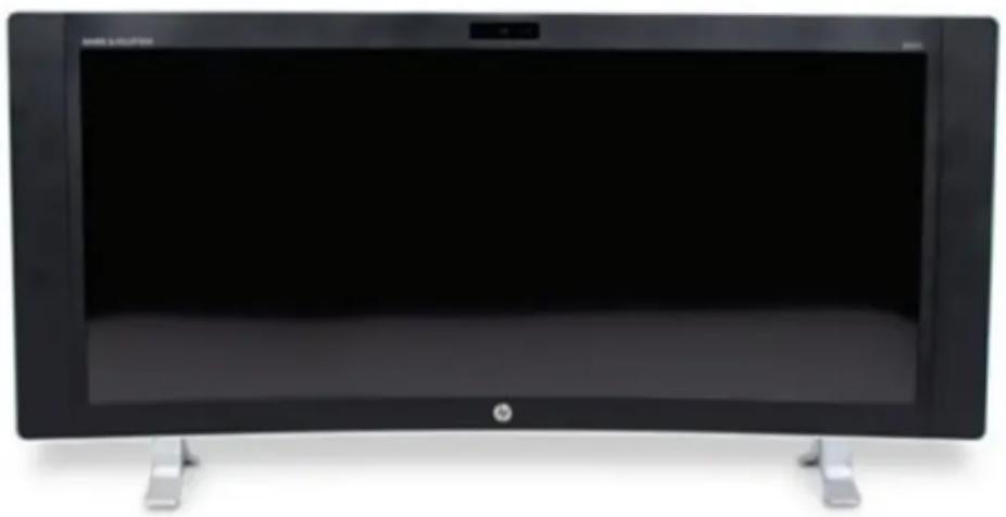

NOTE: For the latest specifications or additional specifications on this product, go to http://www.hp.com/go/ quickspecs/ and search for your specific model to find the model-specific QuickSpecs.
Front components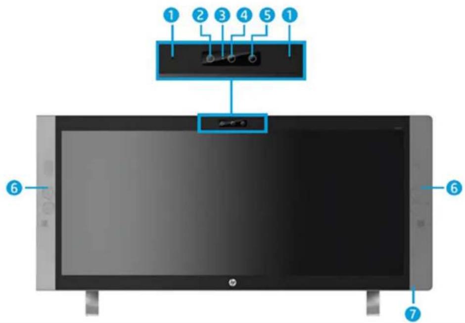
Component Component
| 1 Internal microphones (2) 5 IR projector |
| 2 IR camera 6 Speakers |
| 3 Webcam light 7 Power light |
| 4 Webcam |
Bottom components
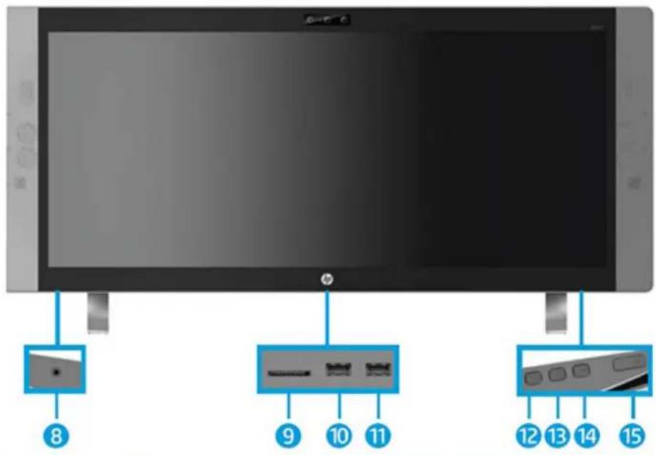
Component
8 Audio-in (microphone)/audio-out (headphone) combo jack 12 Volume/down button
9 Memory card reader 13 Input switch/up button
10 USB 3.0 charging (powered) port 14 Menu/OK button
11 USB 3.0 port 15 Power button
Rear components
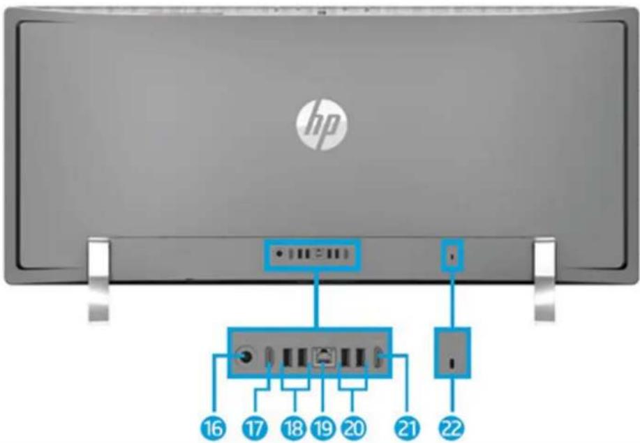
Component
| 16 Power connector 20 USB 2.0 ports (2) |
| 17 HDMI-out port 21 HDMI-in port |
| 18 USB 3.0 ports (2) 22 Security cable slo |
| 19 RJ-45 (network) jack |
Labels
The labels affixed to the computer provide information you may need when you troubleshoot system problems.
- HP platforms preinstalled with Windows 10 do not have the physical label, but have a Digital Product Key electronically installed.

NOTE: This Digital Product Key is automatically recognized and activated by Microsoft Operating Systems on a reinstall of the Windows 10 operating system with HP-approved recovery methods.
- Service label—Provides important information to identify your computer. When contacting support, you will probably be asked for the serial number, and possibly for the product number or the model number. Locate these numbers before you contact support.
- Serial number label
2 Illustrated parts catalog
Component appearance may vary.

NOTE: HP continually improves and changes product parts. For complete and current information on supported parts for your computer, go to http://partsurfer.hp.com, select your country or region, and then follow the on-screen instructions.
System parts
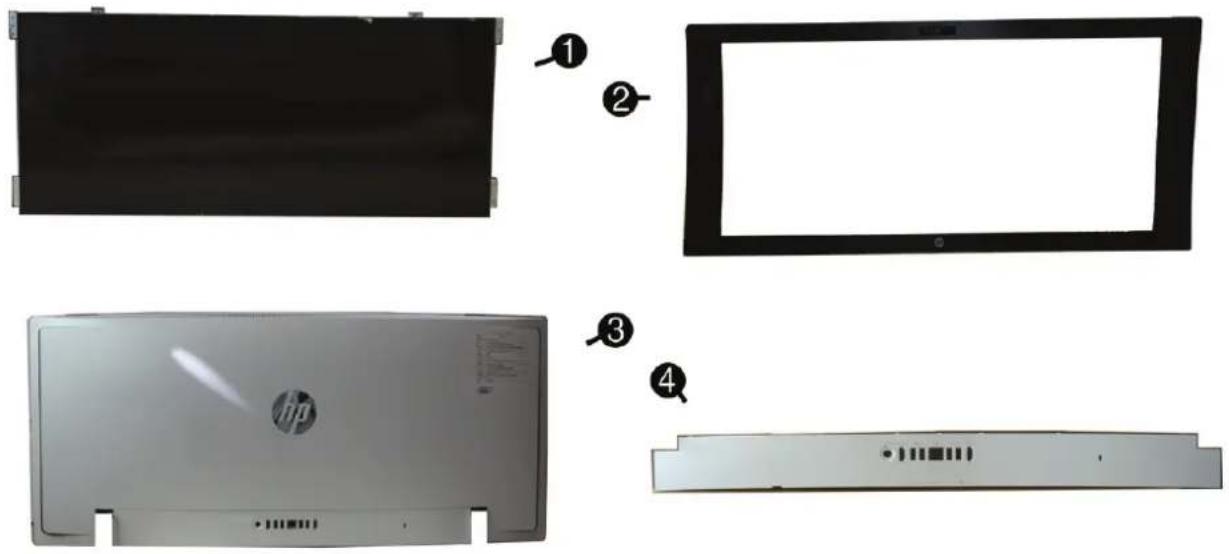
5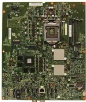
Item Description
| (1) Display |
| ZBD |
| NZBD |
| (2) Front bezel |
| Item Description |
| Adhesive, for use with the front bezel; not illustrated |
| (3) Rear cover |
| (4) I/O cover |
| (5) System board |
| Power supply, 180 W, external; not illustrated |
not illustrated
Misc parts
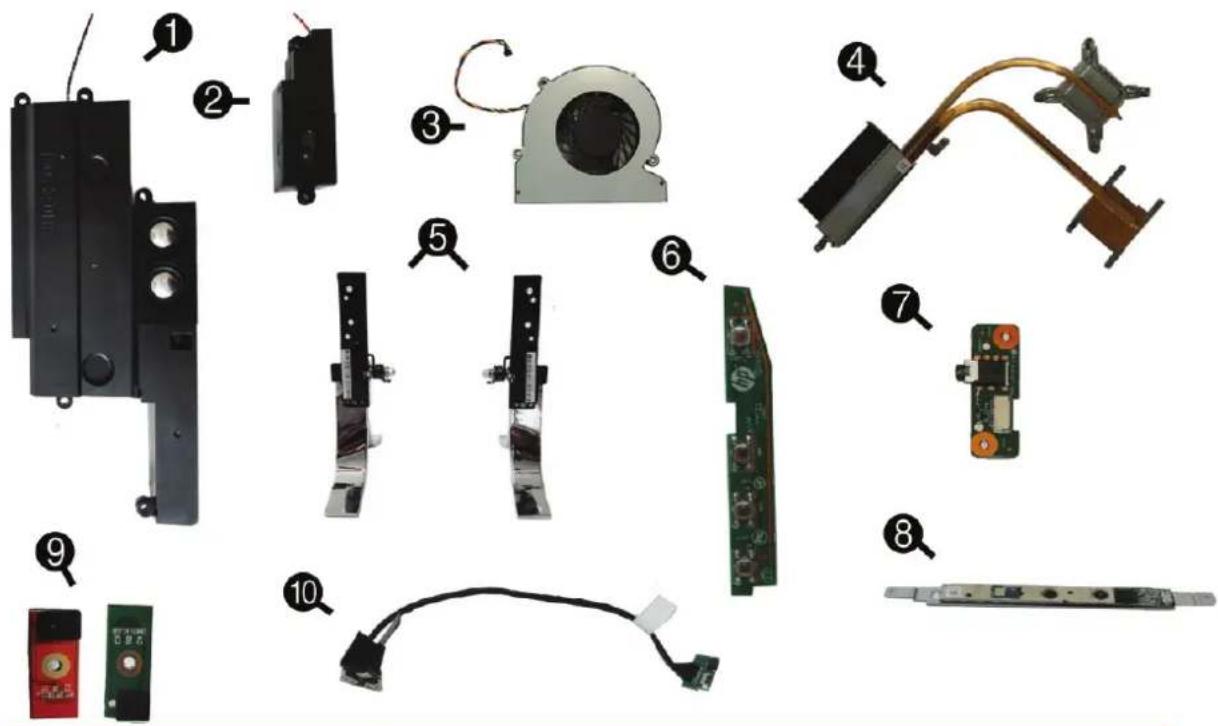
Item Description
(1) Speaker, woofer (2) Speaker, tweeter (3) Fan (4) Heat sink (5) Stand/feet
Right
Left
(6) OSD button board (7) Audio board (8) Webcam module
| Item Description |
| (9) Microphone modules |
| (10) Depth sensor |
| WLAN module, Intel 802.11ac (2x2) WLAN and Bluetooth 4.0 Card |
| Wireless antennas |
| Main |
| Auxiliary |
| Keyboard |
| Power cord |
| not illustrated |
Mass storage devices
| Description |
| External optical drive, DVD ± RW drive |
| Hard drive |
| 2 TB, 5400 rpm, 2.5 inch |
| 1 TB, 7200 rpm, 2.5 inch |
| Solid-state drive (not illustrated) |
| 256-GB solid-state drive, 2280SS, PCIe |
| 128-GB solid-state drive, 2280SS, PCIe |
Processors and memory modules
| Description |
| Memory module (SODIMM; PC4-17000) |
| 8-GB |
| Intel Processors (include replacement thermal material) |
| Intel Core i7-6700T (2.8-GHz) |
| Intel Core i5-6400T (2.2-GHz) |
Cables
| Description |
| Backlight cable |
| LCM 40-pin (EDP SGN) |
| LCM 10-pin (EDP PWR) |
| Transfer cable (F/B side) |
| Transfer cable (M/B side) |
| Hard drive cable |
| Audio cable |
| OSD cable |
3 Routine care, SATA drive guidelines, and disassembly preparation
This chapter provides general service information for the computer. Adherence to the procedures and precautions described in this chapter is essential for proper service.

CAUTION: When the computer is plugged into an AC power source, voltage is always applied to the system board. You must disconnect the power cord from the power source before opening the computer to prevent system board or component damage.
Electrostatic discharge information
A sudden discharge of static electricity from your finger or other conductor can destroy static-sensitive devices or microcircuitry. Often the spark is neither felt nor heard, but damage occurs. An electronic device exposed to electrostatic discharge (ESD) may not appear to be affected at all and can work perfectly throughout a normal cycle. The device may function normally for a while, but it has been degraded in the internal layers, reducing its life expectancy.
Networks built into many integrated circuits provide some protection, but in many cases, the discharge contains enough power to alter device parameters or melt silicon junctions.
Generating static
The following table shows that:
• Different activities generate different amounts of static electricity. • Static electricity increases as humidity decreases.
| Relative Humidity | |||
| Event 55% 40% 10% | |||
| Walking across carpet | 7,500 V | 15,000 V | 35,000 V |
| Walking across vinyl floor | 3,000 V | 5,000 V | 12,000 V |
| Motions of bench worker | 400 V | 800 V | 6,000 V |
| Removing DIPs from plastic tube | 400 V | 700 V | 2,000 V |
| Removing DIPs from vinyl tray | 2,000 V | 4,000 V | 11,500 V |
| Removing DIPs from Styrofoam | 3,500 V | 5,000 V | 14,500 V |
| Removing bubble pack from PCB | 7,000 V | 20,000 V | 26,500 V |
| Packing PCBs in foam-lined box | 5,000 V | 11,000 V | 21,000 V |
| These are then multi-packaged inside plastic tubes, trays, or Styrofoam. | |||

NOTE: 700 volts can degrade a product.
Preventing electrostatic damage to equipment
Many electronic components are sensitive to ESD. Circuitry design and structure determine the degree of sensitivity. The following packaging and grounding precautions are necessary to prevent damage to electric components and accessories.
• To avoid hand contact, transport products in static-safe containers such as tubes, bags, or boxes. - Protect all electrostatic parts and assemblies with conductive or approved containers or packaging. - Keep electrostatic sensitive parts in their containers until they arrive at static-free stations. - Place items on a grounded surface before removing them from their container. • Always be properly grounded when touching a sensitive component or assembly. - Avoid contact with pins, leads, or circuitry. - Place reusable electrostatic-sensitive parts from assemblies in protective packaging or conductive foam.
Personal grounding methods and equipment
Use the following equipment to prevent static electricity damage to equipment:
- Wrist straps are flexible straps with a maximum of one-megohm ± 10% resistance in the ground cords. To provide proper ground, a strap must be worn snug against bare skin. The ground cord must be connected and fit snugly into the banana plug connector on the grounding mat or workstation.
- Heel straps, toe straps, and boot straps can be used at standing workstations and are compatible with most types of shoes or boots. On conductive floors or dissipative floor mats, use them on both feet with a maximum of one-megohm ± 10% resistance between the operator and ground.
| Static Shielding Protection Levels | |
| Method Voltage | |
| Antistatic plastic | 1,500 |
| Carbon-loaded plastic | 7,500 |
| Metallized laminate | 15,000 |
Grounding the work area
To prevent static damage at the work area, use the following precautions:
- Cover the work surface with approved static-dissipative material. Provide a wrist strap connected to the work surface and properly grounded tools and equipment. Use static-dissipative mats, foot straps, or air ionizers to give added protection.
- Handle electrostatic sensitive components, parts, and assemblies by the case or PCB laminate. Handle them only at static-free work areas. Turn off power and input signals before inserting and removing connectors or test equipment. Use fixtures made of static-safe materials when fixtures must directly contact dissipative surfaces.
- Keep work area free of nonconductive materials such as ordinary plastic assembly aids and Styrofoam. Use field service tools, such as cutters, screwdrivers, and vacuums, that are conductive.
Recommended materials and equipment
Materials and equipment that are recommended for use in preventing static electricity include:
- Antistatic tape, antistatic smocks, aprons, or sleeve protectors, conductive bins and other assembly or soldering aids.
- Conductive foam
- Conductive tabletop workstations with ground cord of one-megohm ± 10% resistance, static-dissipative table or floor mats with hard tie to ground, field service kits, static awareness labels, wrist straps and footwear straps providing one-megohm ± 10% resistance, material handling packages, conductive plastic bags, conductive plastic tubes, conductive tote boxes.
- Opaque shielding bags, transparent metallized shielding bags, transparent shielding tubes.
Operating guidelines
To prevent overheating and to help prolong the life of the computer:
- Keep the computer away from excessive moisture, direct sunlight, and extremes of heat and cold.
- Operate the computer on a sturdy, level surface. Leave a 10.2-cm (4-inch) clearance on all vented sides of the computer and above the monitor to permit the required airflow.
- Never restrict the airflow into the computer by blocking any vents or air intakes. Do not place the keyboard, with the keyboard feet down, directly against the front of the desktop unit as this also restricts airflow.
- Occasionally clean the air vents on all vented sides of the computer. Lint, dust, and other foreign matter can block the vents and limit the airflow. Be sure to unplug the computer before cleaning the air vents.
- Never operate the computer with the cover or side panel removed.
- Do not stack computers on top of each other or place computers so near each other that they are subject to each other's re-circulated or preheated air.
- If the computer is to be operated within a separate enclosure, intake and exhaust ventilation must be provided on the enclosure, and the same operating guidelines listed above will still apply.
- Keep liquids away from the computer and keyboard.
- Never cover the ventilation slots on the monitor with any type of material. Install or enable power management functions of the operating system or other software, including sleep states.
Routine care
General cleaning safety precautions
- Never use solvents or flammable solutions to clean the computer.
- Never immerse any parts in water or cleaning solutions; apply any liquids to a clean cloth and then use the cloth on the component.
- Always unplug the computer when cleaning with liquids or damp cloths.
- Always unplug the computer before cleaning the keyboard, mouse, or air vents.
- Disconnect the keyboard before cleaning it.
- Wear safety glasses equipped with side shields when cleaning the keyboard.
Cleaning the Computer Case
Follow all safety precautions in General cleaning safety precautions on page 13 before cleaning the computer.
To clean the computer case, follow the procedures described below:
• To remove light stains or dirt, use plain water with a clean, lint-free cloth or swab. - For stronger stains, use a mild dishwashing liquid diluted with water. Rinse well by wiping it with a cloth or swab dampened with clear water. - For stubborn stains, use isopropyl (rubbing) alcohol. No rinsing is needed as the alcohol will evaporate quickly and not leave a residue. • After cleaning, always wipe the unit with a clean, lint-free cloth. - Occasionally clean the air vents on the computer. Lint and other foreign matter can block the vents and limit the airflow.
Cleaning the keyboard
Follow all safety precautions in General cleaning safety precautions on page 13 before cleaning the keyboard.
To clean the tops of the keys or the keyboard body, follow the procedures described in Cleaning the Computer Case on page 13.
When cleaning debris from under the keys, review all rules in General cleaning safety precautions on page 13 before following these procedures:

CAUTION: Use safety glasses equipped with side shields before attempting to clean debris from under the keys.
- Visible debris underneath or between the keys may be removed by vacuuming or shaking.
- Canned, pressurized air may be used to clean debris from under the keys. Caution should be used as too much air pressure can dislodge lubricants applied under the wide keys.
- If you remove a key, use a specially designed key puller to prevent damage to the keys. This tool is available through many electronic supply outlets.
CAUTION: Never remove a wide leveled key (like the space bar) from the keyboard. If these keys are improperly removed or installed, the keyboard may not function properly.
- Cleaning under a key may be done with a swab moistened with isopropyl alcohol and squeezed out. Be careful not to wipe away lubricants necessary for proper key functions. Use tweezers to remove any fibers or dirt in confined areas. Allow the parts to air dry before reassembly.
Cleaning the display
- Wipe the display screen with a clean cloth moistened with water or with a towelette designed for cleaning displays. Do not use sprays or aerosols directly on the screen; the liquid may seep into the housing and damage a component. Never use solvents or flammable liquids on the display.
Cleaning the mouse
Before cleaning the mouse, ensure that the power to the computer is turned off.
- Clean the mouse ball by first removing the retaining plate and the ball from the housing. Pull out any debris from the ball socket and wipe the ball with a clean, dry cloth before reassembly. • To clean the mouse body, follow the procedures in Cleaning the Computer Case on page 13.
Service considerations
Listed below are some of the considerations that you should keep in mind during the disassembly and assembly of the computer.
Tools and software Requirements
To service the computer, you may need the following tools:
• Torx T-15 screwdriver - Flat-bladed screwdriver (may sometimes be used in place of the Torx screwdriver) • Phillips #2 screwdriver • Diagnostics software • Tamper-resistant T-15 wrench
Screws
The screws used in the computer are not interchangeable. They may have standard or metric threads and may be of different lengths. If an incorrect screw is used during the reassembly process, it can damage the unit. HP strongly recommends that all screws removed during disassembly be kept with the part that was removed, then returned to their proper locations.
CAUTION: Metric screws have a black finish. U.S. screws have a silver finish and are used on hard drives only.
CAUTION: As each subassembly is removed from the computer, it should be placed away from the work area to prevent damage.
Cables and connectors
Most cables used throughout the unit are flat, flexible cables. These cables must be handled with care to avoid damage. Apply only the tension required to seat or unseat the cables during insertion or removal from the connector. Handle cables by the connector whenever possible. In all cases, avoid bending or twisting the cables, and ensure that the cables are routed in such a way that they cannot be caught or snagged by parts being removed or replaced.

CAUTION: When servicing this computer, ensure that cables are placed in their proper location during the reassembly process. Improper cable placement can damage the computer.
Hard Drives
Handle hard drives as delicate, precision components, avoiding all physical shock and vibration. This applies to failed drives as well as replacement spares.
- If a drive must be mailed, place the drive in a bubble-pack mailer or other suitable protective packaging and label the package “Fragile: Handle With Care.”
- Do not remove hard drives from the shipping package for storage. Keep hard drives in their protective packaging until they are actually mounted in the CPU.
- Avoid dropping drives from any height onto any surface.
- If you are inserting or removing a hard drive, turn off the computer. Do not remove a hard drive while the computer is on or in standby mode.
- Before handling a drive, ensure that you are discharged of static electricity. While handling a drive, avoid touching the connector. For more information about preventing electrostatic damage, refer to Electrostatic discharge information on page 10
- Do not use excessive force when inserting a drive.
- Avoid exposing a hard drive to liquids, temperature extremes, or products that have magnetic fields such as monitors or speakers.
Lithium coin cell battery
The battery that comes with the computer provides power to the real-time clock and has a minimum lifetime of about three years.
See the appropriate removal and replacement chapter for the chassis you are working on in this guide for instructions on the replacement procedures.

WARNING! This computer contains a lithium battery. There is a risk of fire and chemical burn if the battery is handled improperly. Do not disassemble, crush, puncture, short external contacts, dispose in water or fire, or expose it to temperatures higher than 140°F (60°C). Do not attempt to recharge the battery.

NOTE: Batteries, battery packs, and accumulators should not be disposed of together with the general household waste. In order to forward them to recycling or proper disposal, please use the public collection system or return them to HP, their authorized partners, or their agents.
SATA hard drive cables
SATA data cable
Always use an HP approved SATA 6.0 Gb/s cable as it is fully backwards compatible with the SATA 1.5 Gb/s drives.
Current HP desktop products ship with SATA 6.0 Gb/s hard drives.
SATA data cables are susceptible to damage if overflexed. Never crease a SATA data cable and never bend it tighter than a 30 mm (1.18 in) radius.
The SATA data cable is a thin, 7-pin cable designed to transmit data for only a single drive.
Cable management
Always follow good cable management practices when working inside the computer.
- Keep cables away from major heat sources like the heat sink.
- Do not jam cables on top of expansion cards or memory modules. Printed circuit cards like these are not designed to take excessive pressure on them.
- Keep cables clear of sliding or moveable parts to prevent them from being cut or crimped when the parts are moved.
- When folding a flat ribbon cable, never fold to a sharp crease. Sharp creases may damage the wires. Some flat ribbon cables come prefolded. Never change the folds on these cables.
- Do not bend any cable sharply. A sharp bend can break the internal wires.
- Never bend a SATA data cable tighter than a 30 mm (1.18 in) radius. • Never crease a SATA data cable.
- Do not rely on components like the drive cage, power supply, or computer cover to push cables down into the chassis. Always position the cables to lay properly by themselves.
4 Removal and Replacement Procedures
The following sections provide information about disassembling various components of the computer.
Preparing to disassemble the computer
To avoid injury and equipment damage, always complete the following steps in order, when opening the HP All-in-One.
- Remove all media from the computer.
- Shut down the computer.
- After the system has completely shut down, disconnect the power adapter from the back of the computer.
- If a cable lock is installed on the rear of the unit, remove the lock.
- Disconnect all other attached cables from the back of the computer.
- Place the computer face down on a soft flat surface. HP recommends that you set down a blanket, towel, or other soft cloth to protect the screen surface from scratches or other damage.
- Since the computer screen is curved, be sure to stabilize the computer on a surface that is free of any items that could damage the display. Be sure the display is secure before disassembly.

WARNING! Beware of sharp edges inside the chassis.
Rear bottom cover
The bottom rear cover hides rear ports and the RTC battery. To remove the cover, remove the caps from atop both screws at the bottom of the computer under the feet, and then turn the screws to loosen the cover. Then pry the cover off the computer. The following image shows screw cover locations.
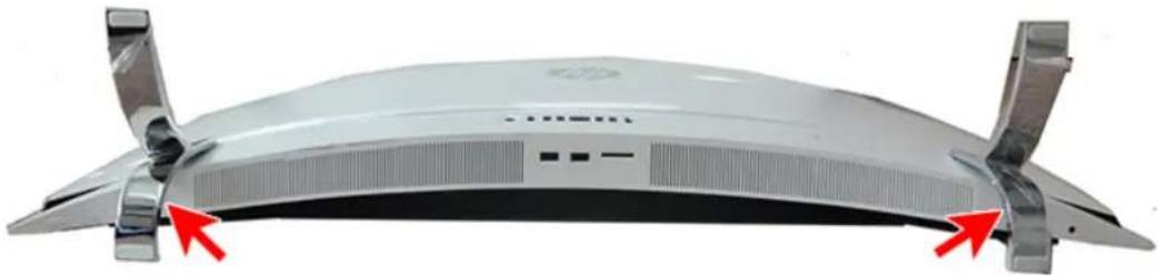
To remove the rear bottom cover:
- Prepare the computer for disassembly (see Preparing to disassemble the computer on page 17).
- Use a tool to pry the screw covers from atop the screws.

NOTE: Only the right screw cover is shown in the following image.
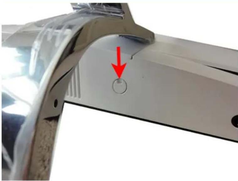
- Turn both screws counter-clockwise until you hear a click and the cover disengages from the chassis.
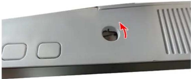
- Pry upward along the bottom of the cover until you remove it from the computer.

NOTE: Only the right side of the cover is shown in the following image.
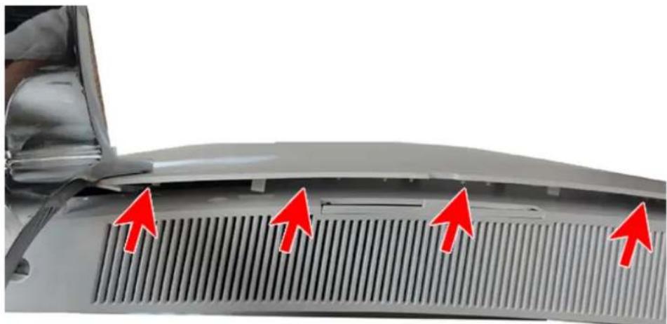
To install the cover, align it and press it down to snap it in place.
RTC battery
The RTC battery is located under the rear bottom cover.
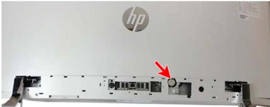
The battery that comes with the computer provides power to the real-time clock. When replacing the battery, use a battery equivalent to the battery originally installed in the computer. The computer comes with a 3-volt lithium coin cell battery.

WARNING! The computer contains an internal lithium manganese dioxide battery. There is a risk of fire and burns if the battery is not handled properly. To reduce the risk of personal injury:
Do not attempt to recharge the battery.
Do not expose to temperatures higher than 60°C (140°F).
Do not disassemble, crush, puncture, short external contacts, or dispose of in fire or water.
Replace the battery only with the HP spare designated for this product.

CAUTION: Before replacing the battery, it is important to back up the computer CMOS settings. When the battery is removed or replaced, the CMOS settings will be cleared.
Static electricity can damage the electronic components of the computer or optional equipment. Before beginning these procedures, ensure that you are discharged of static electricity by briefly touching a grounded metal object.

NOTE: The lifetime of the lithium battery can be extended by plugging the computer into a live AC wall socket. The lithium battery is only used when the computer is NOT connected to AC power.
HP encourages customers to recycle used electronic hardware, HP original print cartridges, and rechargeable batteries. For more information about recycling programs, go to http://www.hp.com/recycle.
To remove the RTC battery:
- Prepare the computer for disassembly (see Preparing to disassemble the computer on page 17).
- Remove the rear bottom cover (see Rear bottom cover on page 18).
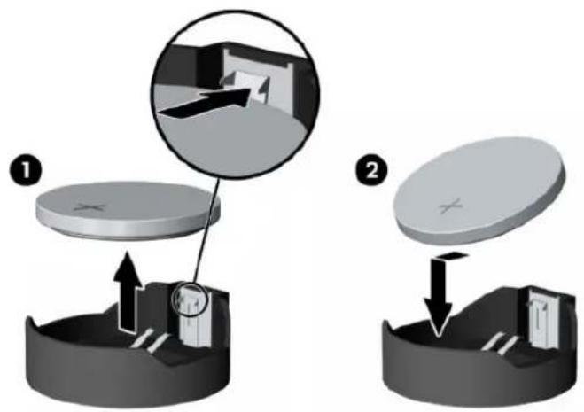
- To remove the RTC battery, press the tab on the inside of the battery socket, and then lift the battery out of the socket (1).
To insert a new battery, slide one edge of the replacement battery under the holder's lip with the positive side up. Push the other edge down until the clamp snaps over the other edge of the battery (2).
USB wireless receiver
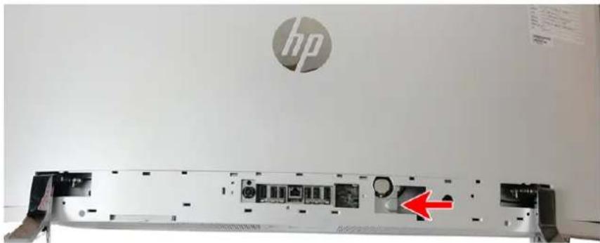
The computer ships with a wireless keyboard and mouse. The USB wireless receiver is located under the rear bottom cover near the RTC battery.
To remove the USB wireless receiver:
- Prepare the computer for disassembly (see Preparing to disassemble the computer on page 17).
- Remove the rear bottom cover (see Rear bottom cover on page 18).
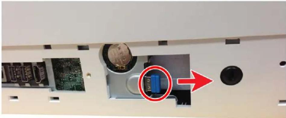
- Pull the receiver toward the right, away from the slot to remove it.
To install the USB receiver, reverse the removal procedure.
Bezel
The bezel is secured with tape underneath. Work around all sides of the bezel, prying it up to remove it. The webcam is housed on the inside, top of the bezel and has two cables that route to a connector board at the top of the chassis.

CAUTION: When prying the bezel off the computer, be careful not to flex the bezel too much, which could result in its breaking.
After you disengage the bezel from the computer, only lift the bezel enough to access the webcam cables underneath. If you lift the bezel too far off the chassis before disconnecting the cables, you could damage the connectors.
To remove the bezel:
- Prepare the computer for disassembly (see Preparing to disassemble the computer on page 17).
- Pry the bezel off the chassis. Work around all sides of the bezel to disengage the tape that secures the bezel to the chassis. Do NOT lift the bezel completely off the computer.
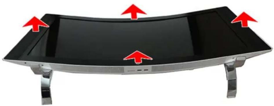
- Lift the top of the bezel enough to access the cables connected to the board underneath, and then disconnect both cables from the board.
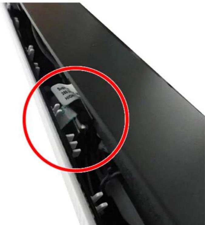
To install the bezel, reverse the removal procedures.
Webcam and microphone modules
The webcam and microphone modules are located on the inside of the top of the bezel. There are three boards — one larger webcam board and two smaller microphone boards that sit underneath the webcam board.
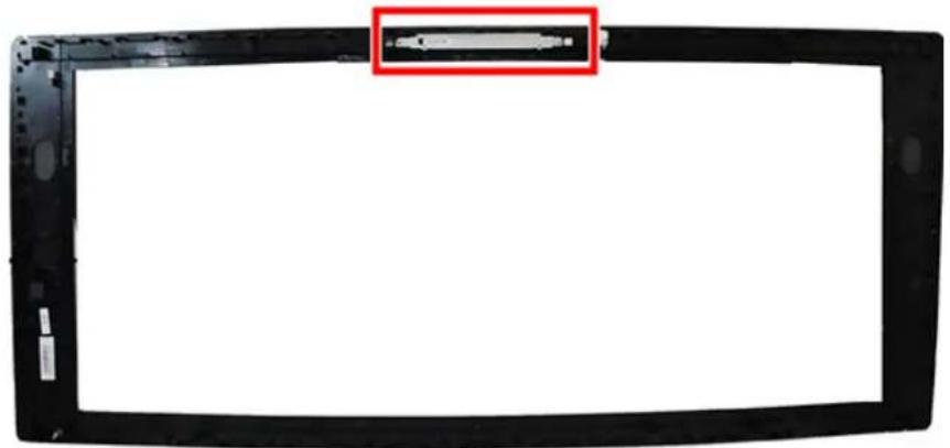
To remove the webcam and microphone modules:
- Prepare the computer for disassembly (see Preparing to disassemble the computer on page 17).
- Remove the bezel (see Bezel on page 23).
- Remove the two Phillips screws (1) that secure the webcam module to the top of the bezel, and then lift the module and place it next to the bezel (2).

- Disconnect the cable from the right (1) and left (2) microphone modules and from the webcam module (3). Remove the modules from the bezel.
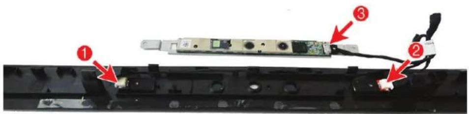
To replace the webcam and microphone modules, reverse the removal procedures.
Display panel
To remove the display panel:
- Prepare the computer for disassembly (see Preparing to disassemble the computer on page 17).
- Remove the bezel (see Bezel on page 23).
- Remove the two Phillips screws (1) that secure the bracket below the display panel, and then lift the bracket out of the computer (2).
- Remove the 12 Phillips screws (3) that secure the display panel to the computer.
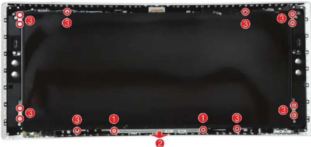
- Rotate the bottom of the display panel upward to access the cables underneath. Use an appropriate wedge (such as a piece of foam) on each side under the display to hold the display up to allow you to disconnect the cables underneath.
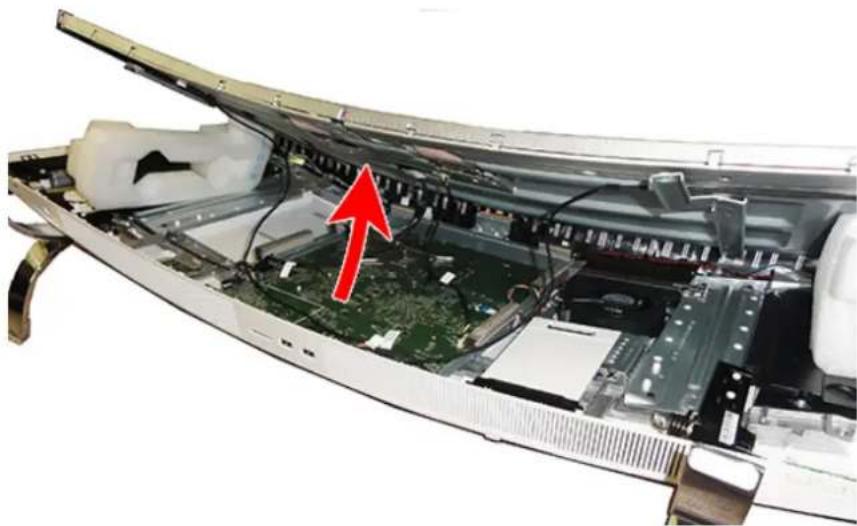
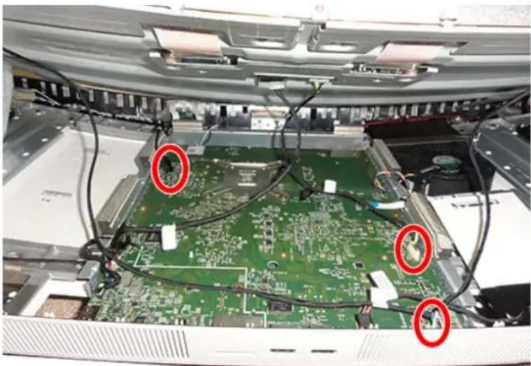
- Disconnect the three display cables from the system board.
- Lift the display panel off the computer.
To replace the display panel, reverse the removal procedures.
WLAN module
The WLAN module is located near the top of the system board, under the display panel. The WLAN module is secured with one Phillips screw and has two connected antennas.

NOTE: The procedure to replace the WLAN module must be performed by an HP technician.
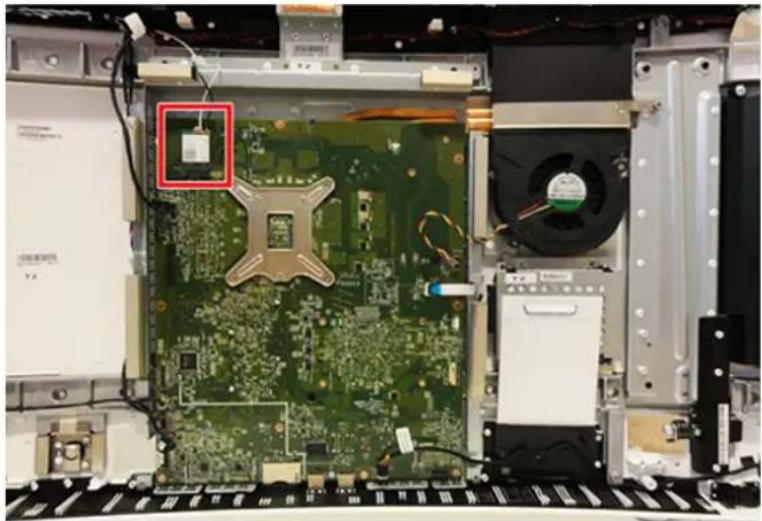
To remove the WLAN module:
- Prepare the computer for disassembly (see Preparing to disassemble the computer on page 17).
- Remove the bezel (see Bezel on page 23).
- Remove the display panel (see Display panel on page 26).
- Disconnect the antenna cables from the module (1).
- Remove the Phillips screw (2) that secures the module to the computer.
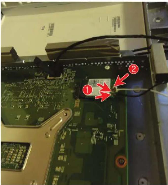
- Lift the module to a 45-degree angle, and then pull it away to remove it from the socket.
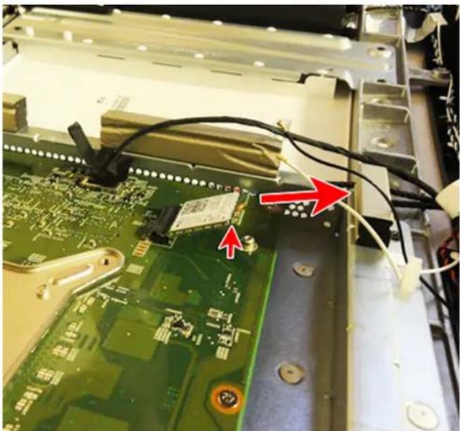
To install the WLAN module, reverse the removal procedures.
When connecting the antennas cables, connect the white cable to the 'Main' connector on the module and the black cable to the 'Aux' connector on the module.

NOTE: WLAN modules are designed with a notch to prevent incorrect insertion.
Hard drive
The hard drive is located under the display panel. The hard drive is housed in a bracket and has a removable connector/cable. One cable connects the drive to the system board.
Description
2 TB, 5400 rpm, 2.5 inch
1 TB, 5400 rpm, 2.5 inch
To remove the hard drive:
- Prepare the computer for disassembly (see Preparing to disassemble the computer on page 17).
- Remove the bezel (see Bezel on page 23).
- Remove the display panel (see Display panel on page 26).
- Slide the label holder out so you can gain access to the hard drive.
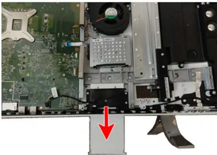
- Disconnect the hard drive cable from the system board (1).
- Remove the three screws (2) that secure the hard drive assembly to the computer.
- Lift the hard drive assembly out of the computer (3).

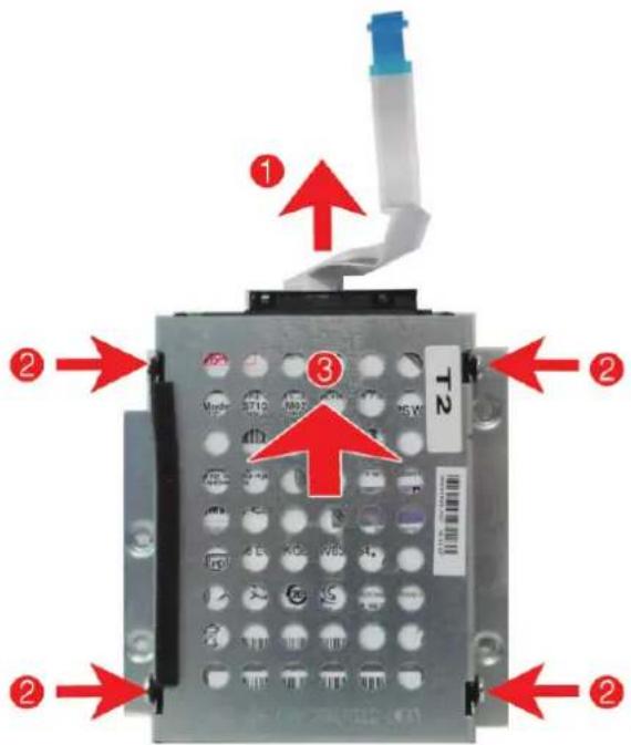
- Disconnect the hard drive connector cable from the hard drive (1), remove the four screws that secure the hard drive to the bracket (2), and slide the drive out of the bracket (3).
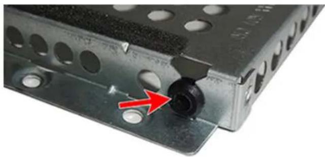
To install a hard drive, reverse the removal procedures. Make sure all four rubber screw grommets are installed correctly for each screw in the bracket as shown in the following image.
OSD (On-Screen Display) board
The OSD board is located near the bottom, right side of the computer.
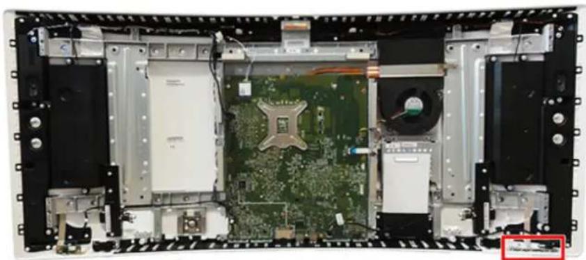
To remove the OSD board:
- Prepare the computer for disassembly (see Preparing to disassemble the computer on page 17).
- Remove the bezel (see Bezel on page 23).
- Remove the display panel (see Display panel on page 26).
- Disconnect the cable from the board (1).
- Remove the tape from the board (2).
- While pulling the tab away from the board (3), lift the board out of the computer (4).
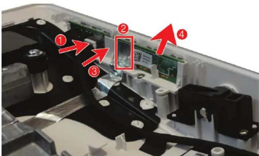
To install the OSD board, reverse the removal procedures.
Audio board
The audio board is located near the bottom, left side of the computer.
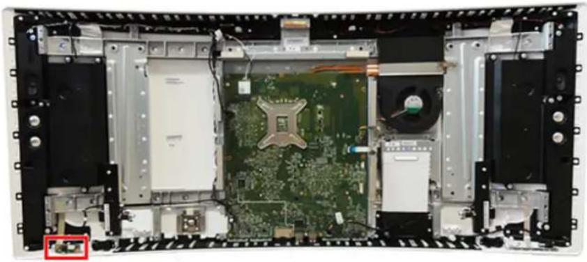
To remove the audio board:
- Prepare the computer for disassembly (see Preparing to disassemble the computer on page 17).
- Remove the bezel (see Bezel on page 23).
- Remove the display panel (see Display panel on page 26).
- Disconnect the cable from the audio board (1).
- Remove the two Phillips screws (2) that secure the trim to the computer.
- Remove the audio board from the computer (3).
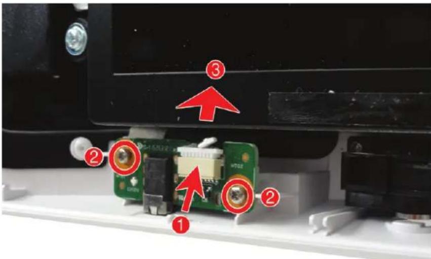
To install the audio board, reverse the removal procedures.
Fan assembly
The fan assembly is located to the right of the system board. You can remove the fan without removing the heat sink.
To remove the fan assembly:
- Prepare the computer for disassembly (see Preparing to disassemble the computer on page 17).
- Remove the bezel (see Bezel on page 23).
- Remove the display panel (see Display panel on page 26).
- Disconnect the fan cable from the system board (1).
- Remove the three Phillips screws that secure the fan to the computer (2).
- Remove the fan from the computer (3).
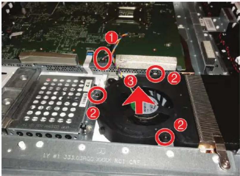
To install the fan assembly, reverse the removal procedures.
Speakers
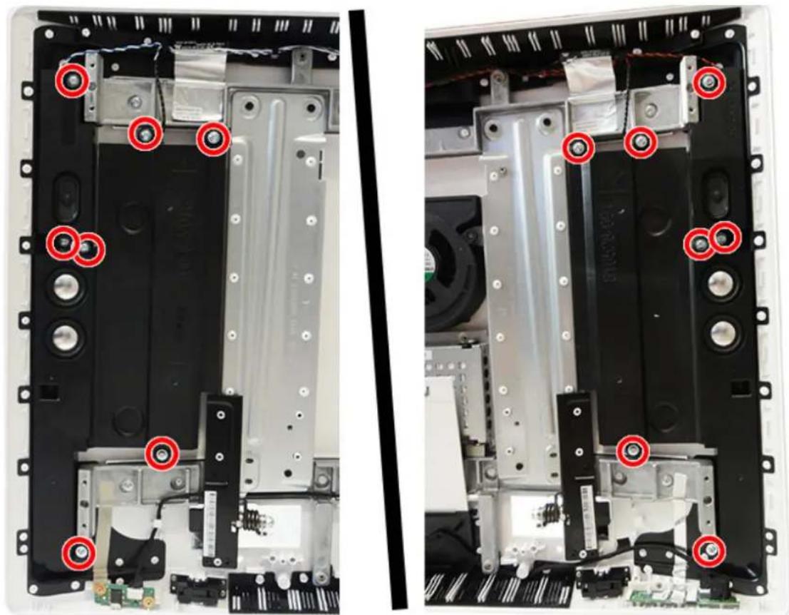
The speaker assemblies are located on both sides of the computer. Each speaker assembly consists of two separate components (four components in all), and is secured with seven screws (14 screws in both speakers).
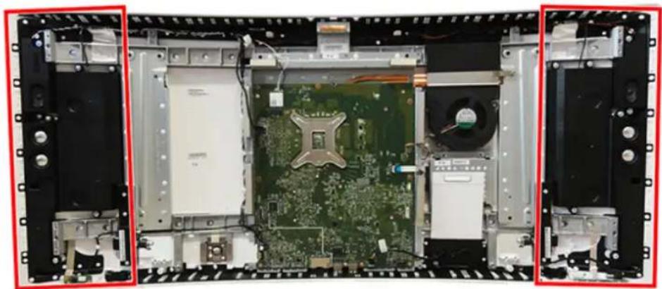
To remove the speakers:
- Prepare the computer for disassembly (see Preparing to disassemble the computer on page 17).
- Remove the bezel (see Bezel on page 23).
- Remove the display panel (see Display panel on page 26).
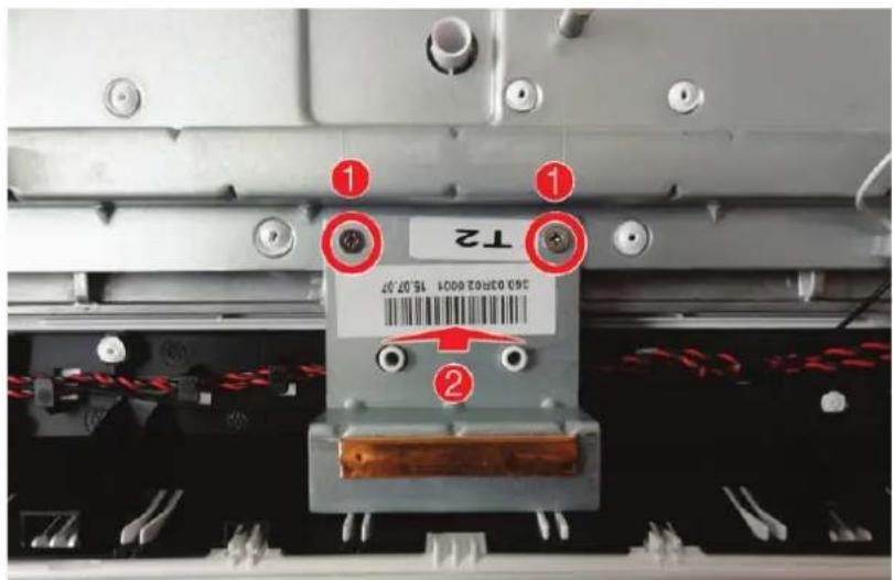
- Remove the bracket from the top of the computer by removing the two Phillips screws (1), and then lifting the bracket out of the computer (2).
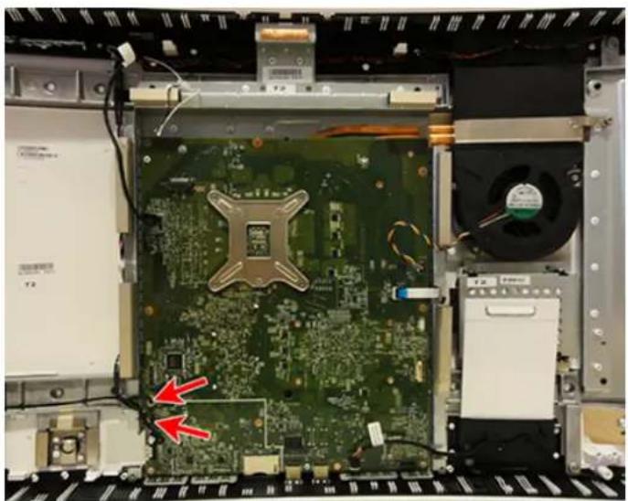
- Disconnect the speaker cables from the system board.
- Remove seven Phillips screws that secure each speaker assembly to the computer.
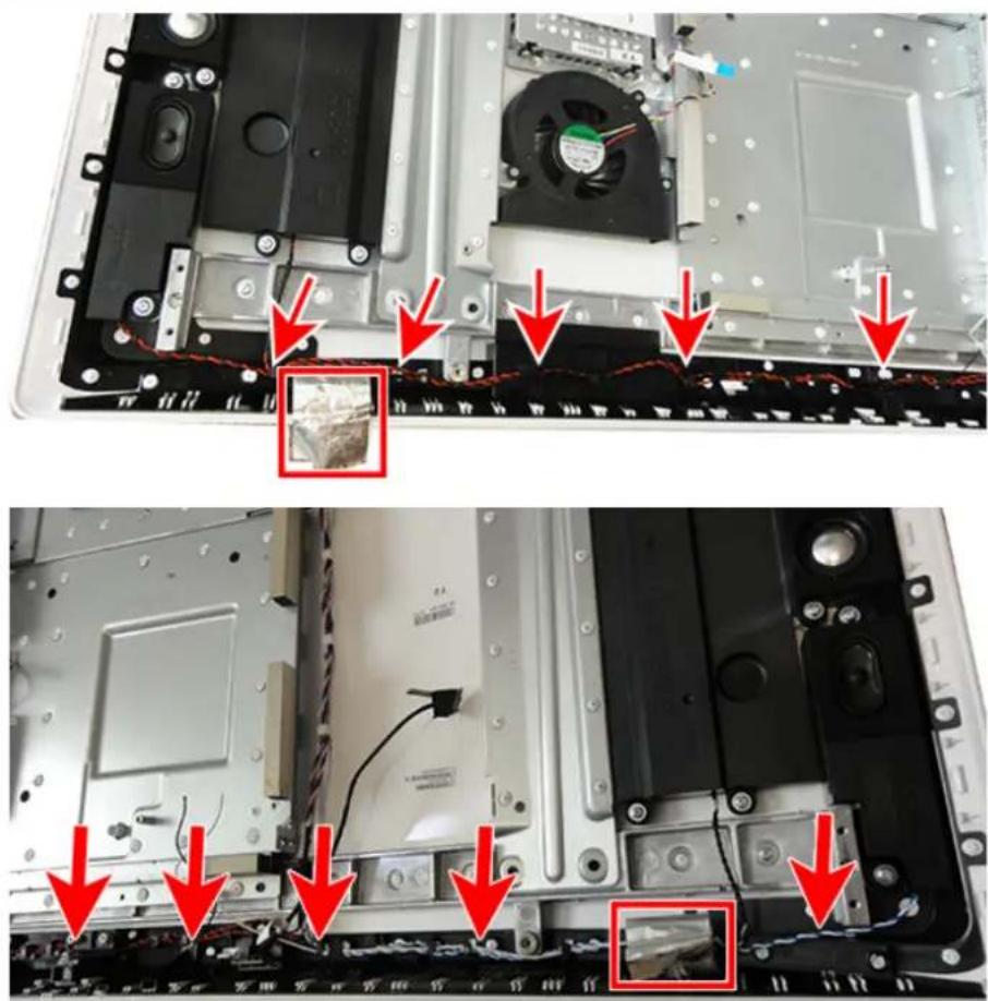
- Lift the WLAN antenna tape from atop the speaker cables on both the left and right sides of the top of the computer, and then remove the speaker cables from the routing path at the top of the computer.

NOTE: Be sure to carefully note the routing of the speaker cables along the top of the computer for reinstallation.
The speaker cables and wireless antenna cables may be intertwined.
- Remove the speaker assemblies from the computer.
To install the speaker assemblies, reverse the removal procedures.
Wireless antennas
The wireless antennas route from the WLAN module via routing paths to transceivers at the top of the computer. The antenna cables route along a similar path as the speaker cables. The transceivers are secured to the computer with adhesive.
To remove the antennas:
- Prepare the computer for disassembly (see Preparing to disassemble the computer on page 17).
- Remove the bezel (see Bezel on page 23).
- Remove the display panel (see Display panel on page 26).
- Disconnect the antenna cables from the WLAN module (1).
- Peel the transceivers off the computer (2).
- Remove the antenna cables from the routing path at the top of the computer (3).
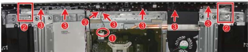
To install the antenna cables and transceivers, reverse the removal procedures.
When connecting the antenna cables, connect the white cable to the 'Main' connector on the module and the black cable to the 'Aux' connector on the module.
Webcam/microphone connector board
The webcam/microphone connector board is located near the top of the computer. The board connects to the webcam and microphone modules that are secured to the inside, top of the bezel.
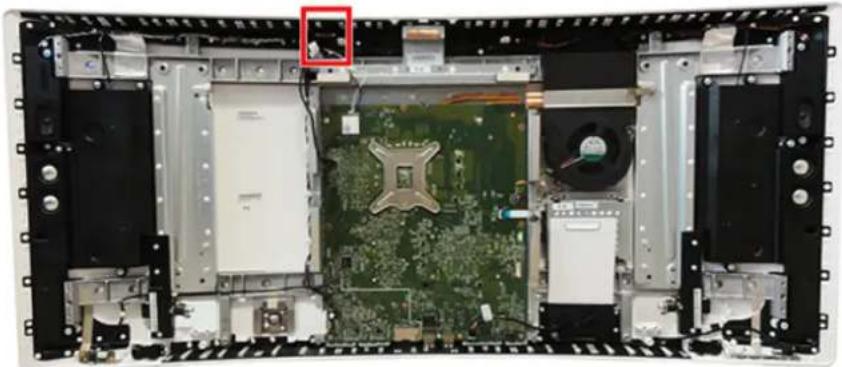
To remove the webcam/microphone connector board:
- Prepare the computer for disassembly (see Preparing to disassemble the computer on page 17).
- Remove the bezel (see Bezel on page 23).
- Remove the display panel (see Display panel on page 26).
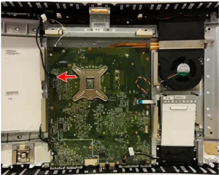
- Disconnect the webcam/microphone connector board cable from the system board.
- Pull the tabs on each side of the board (1), and then lift the board out of the computer (2).
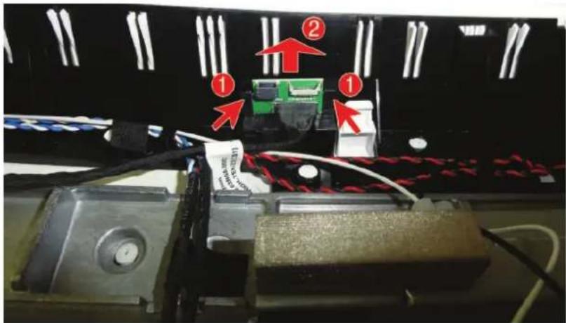
To install the webcam/microphone connector board, reverse the removal procedures.
Feet
Each foot is secured to the inside of the computer with four screws.
To remove the feet:
- Prepare the computer for disassembly (see Preparing to disassemble the computer on page 17).
- Remove the bezel (see Bezel on page 23).
- Remove the display panel (see Display panel on page 26).
- Remove the four Phillips screws that secure each foot to the inside of the computer.
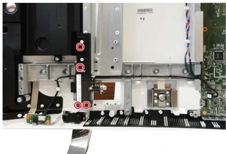
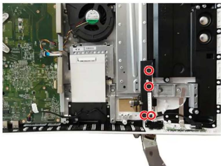
- Rotate the top of each foot upward (right foot illustrated below).
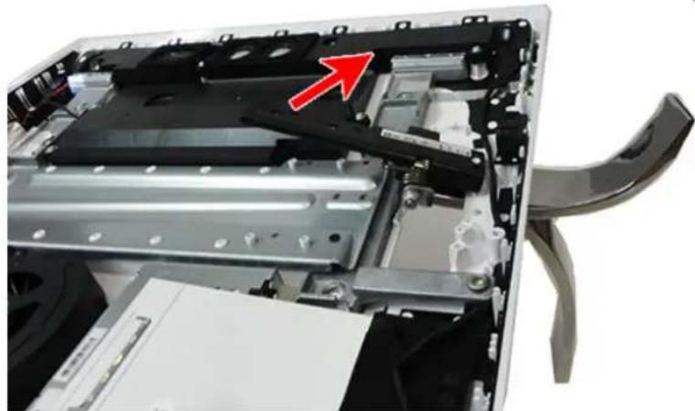
- Pull the foot down through the hole in the rear of the computer to remove it.
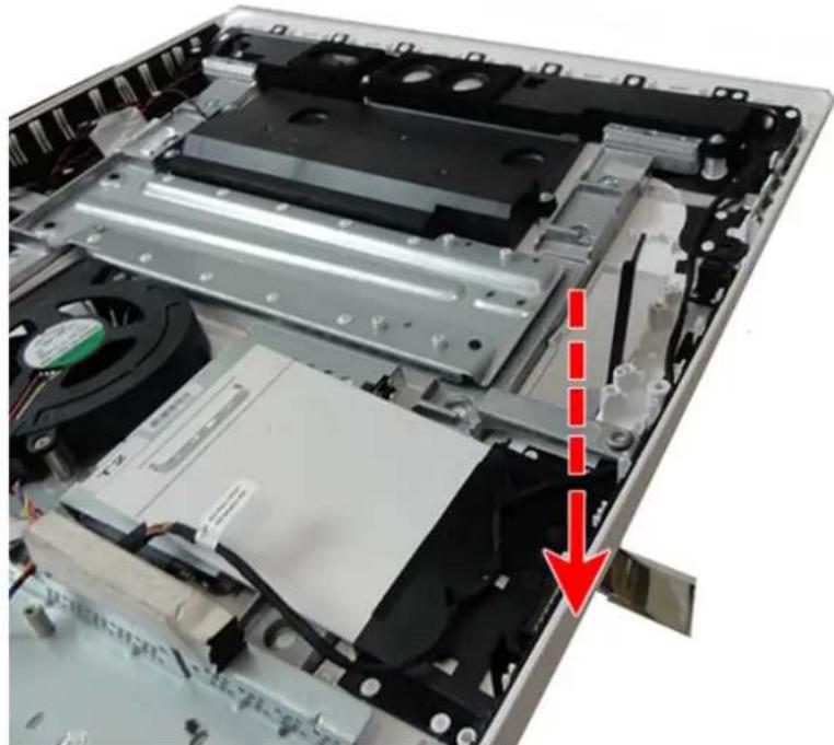
To install the feet, reverse the removal procedures.
System board
To remove the system board:
- Prepare the computer for disassembly (see Preparing to disassemble the computer on page 17).
- Remove the bezel (see Bezel on page 23).
- Remove the display panel (see Display panel on page 26).
- Remove the WLAN module (see WLAN module on page 28).
- Remove the USB receiver (see USB wireless receiver on page 22).
- Disconnect the following cables from the system board, noting their location for reinstallation:
(1): Webcam/microphone connector board cable (2): Fan cable (3): Hard drive cable (4): Speaker (tweeter) cable (5): Speaker (subwoofer) cable (6): Audio board cable (7): OSD board cable
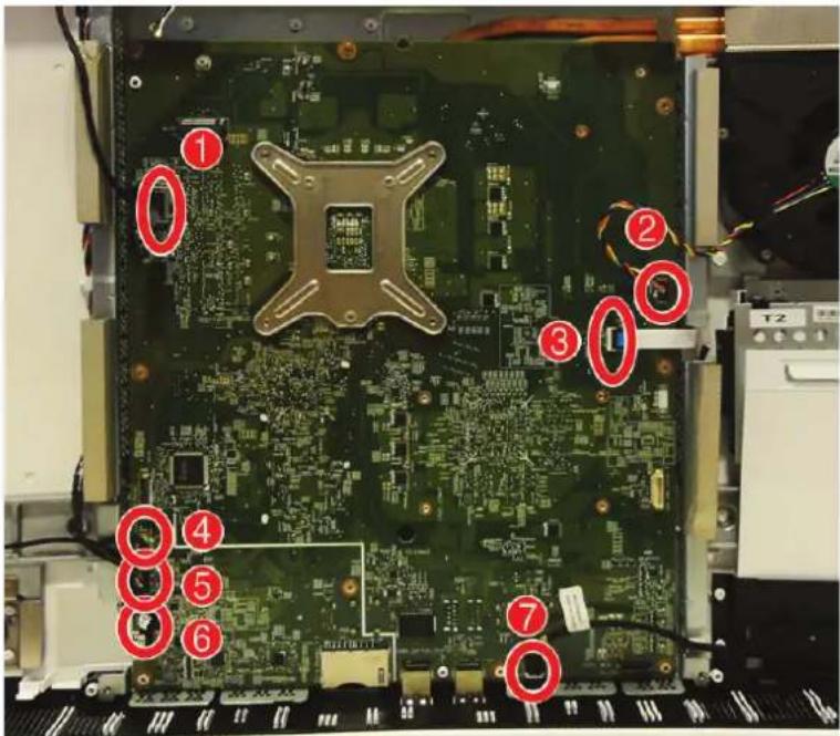
- Remove the nine Phillips screws that secure the system board to the computer.
- Loosen the screw that secures the heat sink to the computer.
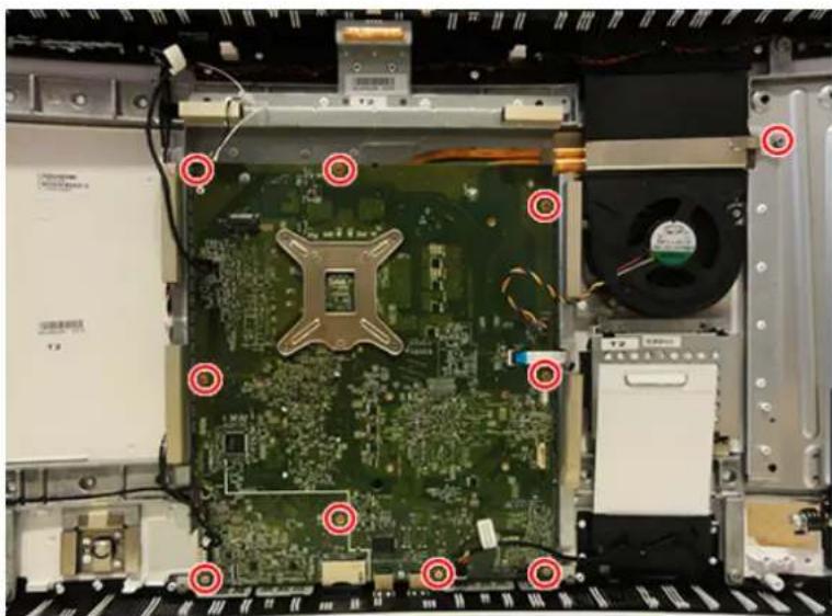
- Lift the system board up and out of the computer.
To install the system board, reverse the removal procedures.
Updating SMBIOS Information
When replacing the system board, you must reprogram the SMBIOS information on the affected computer. Failure to reprogram the board will result in eventual failure, such as an activation failure (need to reactivate the system) or a system recovery failure.
To update SMBIOS information in Computer Setup:
- Turn on or restart the computer.
- Press Esc while the "Press the ESC key for Startup Menu" message is displayed at the bottom of the screen.

NOTE: If you do not press Esc at the appropriate time, you must restart the computer and again press Esc when the monitor light turns green to access the utility.
- Press F10 to enter Computer Setup.
- Go to Main > Set Machine Unique Data.
- If necessary, press Ctrl+A to initiate edit mode.
- Edit the fields listed. If the feature byte has data or is not editable, then it was not cleared and cannot be edited.
System ID Setup Page
| Setup Field Name Comment Label | |
| Product Name Enter the Model name/number or marketing name. Flexbuild | |
| Serial Number Enter the Serial Number of Unit. Support | |
| SKU Number Enter the SKU or Product Number including Localization Code. Support | |
| Asset Tag Enter the 18-byte identifier assigned to the computer. Support | |
| Feature Byte Enter the Feature Byte string. The feature byte string is case sensitive. | Flexbuild |
| The label includes spaces after every four characters. You can enter or ignore these spaces – their only purpose is to help with data entry. There is a character limitation of 40 bytes per line. When you reach this limit, go to the next line to continue data entry. BIOS ignores the spaces and lines. | |
| If you make an error during data entry, the data will not validate, and the computer asks you to correct your data input. | |
| Build ID The Build ID of the unit. Flexbuild | |
System board callouts
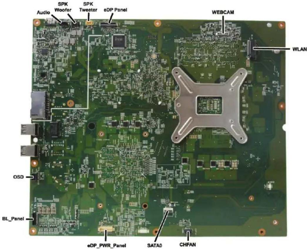
| Sys Bd Label Color Component Sys Bd Label Color Component | |||||
| Audio Black Audio board connector CHFAN Black Fan connector | |||||
| SPK Tweeter Black Speaker connector SATA0 White Hard drive connector | |||||
| SPK Woofer White Speaker connector eDP_PWR_Panel White Display panel connector | |||||
| eDP Panel | Black | Display panel connector | BL_Panel | Black | Display panel connector |
| WEBCAM | Black Webcam/microphone board connector | OSD | Black OSD board connector | ||
| WLAN | Black Wireless module connector | ||||
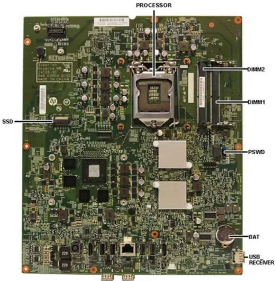
| Sys Bd Label Color Component Sys Bd Label Color Component | |||||
| Processor | Silver | Processor socket | BAT | Black | RTC battery socket |
| DIMM1 | Black | Memory module socket | USB_RECEIVER | Silver | Wireless USB receiver |
| DIMM2 | Black Memory module socket SSD | Black Solid-state drive | connector | ||
| PSWD | Blue | Password jumper | |||
Memory
The computer comes with small outline dual inline memory modules (SODIMMs).
The memory sockets on the system board can be populated with up to two industry-standard SODIMMs.
These memory sockets are populated with at least one preinstalled SODIMM.
For proper system operation, the SODIMMs must meet the following qualifications:
| SODIMM 1.35 volt DDR3L-SDRAM SODIMMs | |
| Compliance unbuffered non-ECC PC4-17000 DDR4-2133 MHz-compliant | |
| Pins | industry-standard 260 pin containing the mandatory Joint Electronic Device Engineering Council (JEDEC) specification |
| Support support CAS latency 11 DDR4 2133 MHz (11-11-11 timing) | |
| Slots 2 | |
| Maximum Memory 8 GB | |
| Supported | 1 Gbit, 2 Gbit, and 4 Gbit non-ECC memory technologies single-sided and double-sided SODIMMs |
| Note The system will not operate properly if you install unsupported SODIMM memory. SODIMMs constructed with x8 and x16 SDRAMs are supported; SODIMMs constructed with x4 SDRAMs are not supported. | |
HP offers upgrade memory for this computer and advises that the consumer purchase it to avoid compatibility issues with unsupported third-party memory.
The system will automatically operate in single channel mode, dual channel mode, or flex mode, depending on how the SODIMMs are installed. Refer to the following table to identify the SODIMM channel locations.
| Location System board label Channel |
| Lower Socket DIMM1 Channel A |
| Upper Socket DIMM2 Channel B |
- The system will operate in single channel mode if the SODIMM sockets are populated in one channel only.
- The system will operate in flex mode if the memory capacity of the SODIMM in Channel A is not equal to the memory capacity of the SODIMM in Channel B. In flex mode, the channel populated with the least amount of memory describes the total amount of memory assigned to dual channel and the remainder is assigned to single channel. If one channel will have more memory than the other, the larger amount should be assigned to channel A.
- The system will operate in a higher-performing dual channel mode if the memory capacity of the SODIMM in Channel A is equal to the memory capacity of the SODIMM in Channel B. In any mode, the maximum operational speed is determined by the slowest SODIMM in the system.
To remove a memory module:
- Prepare the computer for disassembly (see Preparing to disassemble the computer on page 17).
- Remove the bezel (see Bezel on page 23).
- Remove the display panel (see Display panel on page 26).
- Remove the system board (see System board on page 43), and then turn it over.
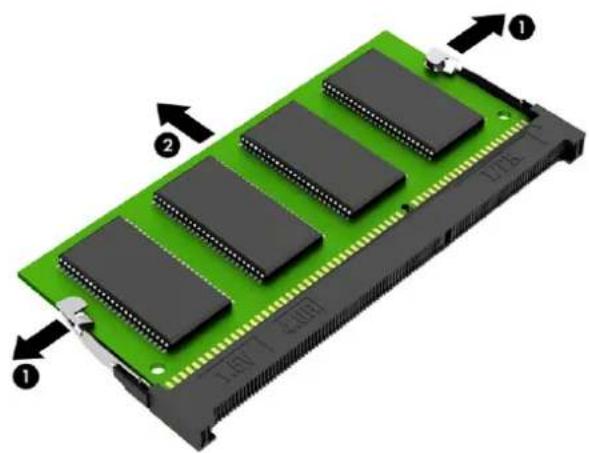
- To remove a memory module, press outward on the two latches on each side of the SODIMM (1), then pull the SODIMM out of the socket (2).
- To install a memory module, position the notch (1) correctly into the socket, slide the SODIMM into the socket at approximately a 30° angle (2), then press the SODIMM down (3) so that the latches lock it in place.
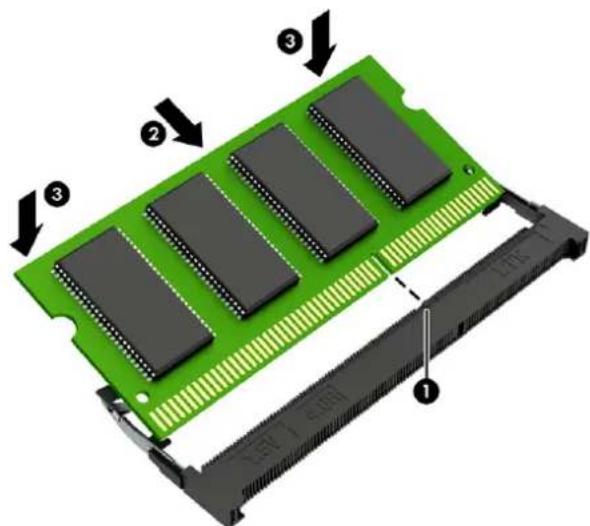

NOTE: A memory module can be installed in only one way. Match the notch on the module with the tab on the memory socket.
The computer automatically recognizes the additional memory when you turn on the computer.
Heat sink
The heat sink is secured to the system board. You have to remove the system board and flip it over to remove the heat sink.
To remove the heat sink:
- Prepare the computer for disassembly (see Preparing to disassemble the computer on page 17).
- Remove the bezel (see Bezel on page 23).
- Remove the display panel (see Display panel on page 26).
- Remove the system board (see System board on page 43), and then turn it over.
- In the order indicated on the heat sink, loosen the nine captive Phillips screws that secure the heat sink to the system board.
CAUTION: Remove heat sink retaining screws in diagonally opposite pairs (as in an X) to even the downward forces on the processors. This is especially important as the pins on the sockets are very fragile and any damage to them may require replacing the system board.
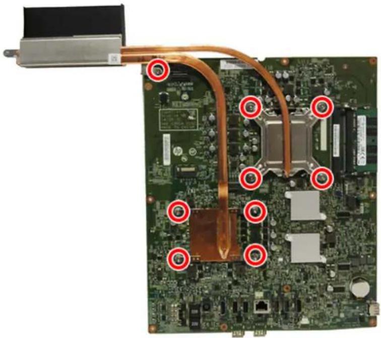
- Lift the heat sink out of the computer.
CAUTION: To reduce degradation in thermal performance, be sure not to touch the thermal grease on the surface of the processor or the heat sink.
To replace the heat sink, reverse the removal procedures.
Processor
Description
Intel Core i7-6700T (2.8-GHz)
Intel Core i5-6400T (2.2-GHz)
To remove the processor:
- Prepare the computer for disassembly (see Preparing to disassemble the computer on page 17).
- Remove the bezel (see Bezel on page 23).
- Remove the display panel (see Display panel on page 26).
- Remove the system board (see System board on page 43), and then turn it over.
- Remove the heat sink (see Heat sink on page 49).
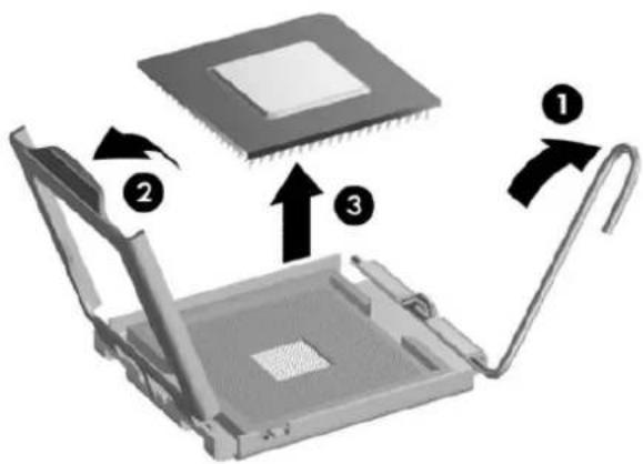
- Rotate the locking lever to its full open position (1).
- Raise and rotate the microprocessor retainer to its fully open position (2), and then carefully lift the processor from the socket (3).
CAUTION: Do NOT handle the pins in the processor socket. These pins are very fragile and handling them could cause irreparable damage. Once pins are damaged it may be necessary to replace the system board.
The heat sink must be installed within 24 hours of installing the processor to prevent damage to the processor's solder connections.

NOTE: After installing a new processor onto the system board, always update the system ROM to ensure that the latest version of the BIOS is being used on the computer. The latest system BIOS can be found on the Web at: http://www.hp.com.
Solid-state drive (M.2)
Description
256-GB solid-state drive, 2280SS, PCIe
128-GB solid-state drive, 2280SS, PCIe
Before removing the solid-state drive, follow these steps:
To remove the solid-state drive:
- Prepare the computer for disassembly (see Preparing to disassemble the computer on page 17).
- Remove the bezel (see Bezel on page 23).
- Remove the display panel (see Display panel on page 26).
- Remove the system board (see System board on page 43), and then turn it over.
Remove the solid-state drive:
- Remove the Phillips PM2.0×3.5 screw (1) that secures the solid-state drive to the system board.

NOTE: If the module springs up when the screw is removed, be sure to remove the module at the angle dictated by the spring mechanism.
When installing the module, be sure to insert the module at the angle that it sits after the screw is removed and the module springs up.
- Remove the solid-state drive (2) by pulling the drive away from the slot at an angle.
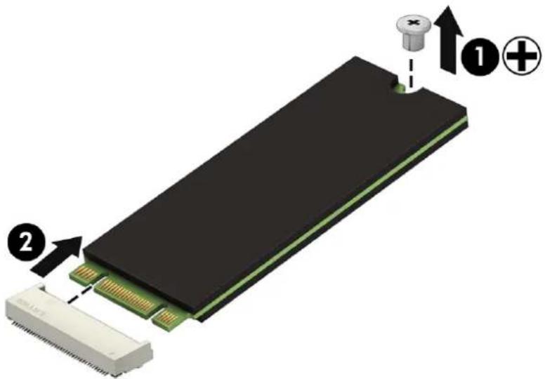
Reverse this procedure to install the solid-state drive.
5 Computer Setup (F10) Utility
Computer Setup (F10) Utilities
Use Computer Setup (F10) Utility to do the following:
• Change factory default settings. - Set the system date and time. - Set, view, change, or verify the system configuration, including settings for processor, graphics, memory, audio, storage, communications, and input devices. - Modify the boot order of bootable devices such as hard drives, optical drives, or USB flash media devices. - Enable Quick Boot, which is faster than Full Boot but does not run all of the diagnostic tests run during a Full Boot. You can set the system to:
■ always Fast Boot (default); ■ periodically Full Boot (from every 1 to 30 days); or ■ always Full Boot.
- Select Post Messages Enabled or Disabled to change the display status of Power-On Self-Test (POST) messages. Post Messages Disabled suppresses most POST messages, such as memory count, product name, and other non-error text messages. If a POST error occurs, the error is displayed regardless of the mode selected. To manually switch to Post Messages Enabled during POST, press any key (except F1 through F12).
- Establish an Ownership Tag, the text of which is displayed each time the system is turned on or restarted.
- Enter the Asset Tag or property identification number assigned by the company to this computer.
- Enable the power-on password prompt during system restarts (warm boots) as well as during power-on.
- Establish a setup password that controls access to the Computer Setup (F10) Utility and the settings described in this section.
- Secure integrated I/O functionality, including the USB ports, audio, or embedded NIC, so that they cannot be used until they are unsecured.
- Enable or disable removable media boot ability.
- Solve system configuration errors detected but not automatically fixed during the Power-On Self-Test (POST).
- Replicate the system setup by saving system configuration information on a USB device and restoring it on one or more computers.
- Execute self-tests on a specified ATA hard drive (when supported by drive).
- Enable or disable DriveLock security (when supported by drive).
Using Computer Setup (F10) Utilities
Computer Setup can be accessed only by turning the computer on or restarting the system. To access the Computer Setup Utilities menu, complete the following steps:
- Turn on or restart the computer.
- Repeatedly press F10 when the monitor light turns green to access the utility.
You can also press Esc to a menu that allows you to access different options available at startup, including the Computer Setup utility.
NOTE: If you do not press F10 at the appropriate time, you must restart the computer and again repeatedly press F10 when the monitor light turns green to access the utility. NOTE: If the Computer Setup (F10) Utility is set to "fast boot", use one of the following procedures to access Computer Setup:
- Before turning on the computer, press and hold F10. Turn on the computer and continue to hold F10 until the Computer Setup (F10) Utility is displayed.
- or -
- Follow the Windows 8.1 instructions for rebooting the computer into the Computer Setup (F10) Utility.
- A choice of five headings appears in the Computer Setup Utilities menu: File, Storage, Security, Power, and Advanced.
- Use the arrow (left and right) keys to select the appropriate heading. Use the arrow (up and down) keys to select the option you want, then press Enter. To return to the Computer Setup Utilities menu, press Esc.
- To apply and save changes, select File > Save Changes and Exit.
- If you have made changes that you do not want applied, select Ignore Changes and Exit.
- To reset to factory settings or previously saved default settings (some models), select Apply Defaults and Exit. This option will restore the original factory system defaults.
NOTE: Not all settings shown in the following sections are available for all models.
CAUTION: Do NOT turn the computer power OFF while the BIOS is saving the Computer Setup (F10) changes because the CMOS could become corrupted. It is safe to turn off the computer only after exiting the F10 Setup screen.

NOTE: Support for specific Computer Setup options may vary depending on the hardware configuration.
Table 5-1 Computer Setup—File
| Option Description | |
| System Information Lists: | |
| ManufacturerProduct nameSKU numberSerial numberBorn on DateSystem board ID and CT numberBIOS RevisionBIOS RevisionBIOS DateProcessor type and speedInstalled memory size/speed, number of channels (single or dual) (if applicable) | |
| About Displays copyright notice. | |
| Set Time and Date Allows you to set system time and date. | |
| Default Setup Save Current Settings as Default | |
| Saves the current system configuration settings as the default. | |
| Restore Factory Settings as Default | |
| Restores the factory system configuration settings as the default. | |
| Apply Defaults and Exit | Applies the currently selected default settings and clears any established passwords. |
| Ignore Changes and Exit Exits Computer Setup without applying or saving any changes. | |
| Save Changes and Exit | Saves changes to system configuration or default settings and exits Computer Setup. |

NOTE: Support for specific Computer Setup options may vary depending on the hardware configuration.
Table 5-2 Computer Setup—Storage
| Option Description | |
| DeviceConfiguration | Lists all installed BIOS-controlled storage devices.When a device is selected, detailed information and options are displayed. The following options may be presented:Hard Disk:Size, model, firmware version, serial number. |
| Storage Options SATA Emulation | |
| Allows you to choose how the SATA controller and devices are accessed by the operating system. Supported options include: IDE and AHCI (default).CAUTION:SATA emulation changes may prevent access to existing hard drive data and degrade or corrupt established volumes.IDE Mode- This is the default and most backwards-compatible setting of the options. Operating systems usually do not require additional driver support in IDE mode. Use this option for "normal" (non-RAID) configurationsAHCI Mode (default option) - Allows operating systems with AHCI device drivers loaded to take advantage of more advanced features of the SATA controller.Removable Media BootEnables/disables ability to boot the system from removable media. Default is enabled. | |
| DPS Self-Test | Allows you to execute self-tests on ATA hard drives capable of performing the Drive Protection System (DPS) self-tests.NOTE:This selection will only appear when at least one drive capable of performing the DPS self-tests is attached to the system. |
| Boot Order Allows you to:UEFI Boot Sources:Specify the order in which EFI boot sources (such as a internal hard drive, USB hard drive, USB optical drive, or internal optical drive) are checked for a bootable operating system image. Each device on the list may be individually excluded from or included for consideration as a bootable operating system source.EFI boot sources always have precedence over legacy boot sources.Legacy Boot Sources:Specify the order in which legacy boot sources (such as a network interface card, internal hard drive, USB optical drive, or internal optical drive) are checked for a bootable operating system image. Each device on the list may be individually excluded from or included for consideration as a bootable operating system source.Specify the order of attached hard drives. The first hard drive in the order will have priority in the boot sequence and will be recognized as drive C (if any devices are attached).NOTE:To drag a device to a preferred place, press Enter. To remove the device from consideration as a bootable device, press F5.You can use F5 to disable individual boot items, as well as disable EFI boot and/or legacy boot.NOTE:MS-DOS drive lettering assignments may not apply after a non-MS-DOS operating system has started.Shortcut to Temporarily Override Boot OrderTo boot one time from a device other than the default device specified in Boot Order, restart the computer and press Esc (to access the boot menu) and then F9 (Boot Order), or only F9 (skipping the boot menu) when the monitor light turns green. After POST is completed, a list of bootable devices is displayed. Use the arrow keys to select the preferred bootable device and press Enter. The computer then boots from the selected non-default device for this one time. | |

NOTE: Support for specific Computer Setup options may vary depending on the hardware configuration.
Table 5-3 Computer Setup—Security
| Option Description | |
| Setup Password Allows you to set and enable a setup (administrator) password. | |
| NOTE: If the setup password is set, it is required to change Computer Setup options, flash the ROM, and make changes to certain plug and play settings under Windows. | |
| Power-On Password | Allows you to set and enable a power-on password. The power-on password prompt appears after a power cycle or reboot. If the user does not enter the correct power-on password, the unit will not boot. |
| Password Options(This selection appears only if a power-on password or setup password is set.) | Allows you to enable/disable:Lock Legacy Resources (determines whether or not Windows Device Manager is allowed to change resource settings for serial and parallel ports).Stringent security (enabling the stringent password disables the ability to reset the password by moving the jumper on the system board). Default is disabled.CAUTION: If you enable the stringent security feature and you forget the setup password or the power-on password, the computer is inaccessible and can no longer be used.If you lose or forget the password, the system board must be replaced. This scenario is not covered under warranty.To prevent the computer from becoming permanently unusable, record your configured setup password or power-on password in a safe place away from your computer. Without these passwords, the computer cannot be unlocked.Setup Browse Mode (appears if a setup password is set) (allows viewing, but not changing, the F10 Setup Options without entering setup password). Default is enabled.Password prompt on F9 & F12 (requires setup password to use these boot functions). Default is enabled.Network Server Mode. Default is disabled. |
| Device Security | Allows you to set Device Available/Device Hidden (default is Device Available) for:Embedded security deviceSystem audioNetwork controllerSATA ports (varies by model) |
| USB Security Allows you to set Enabled/Disabled (default is Enabled) for:Front USB PortsRear USB PortsInternal USB Ports | |
| Slot Security Allows you to disable any M.2 card slot. Default is enabled. | |
| Network Boot | Enables/disables the computer's ability to boot from an operating system installed on a network server. Default is enabled. |
| System IDs Allows you to set:Product NameSerial Number | |
| Universal Unique Identifier (UUID) number. The UUID can only be updated if the current chassis serial number is invalid. (These ID numbers are normally set in the factory and are used to uniquely identify the system.)SKU NumberFamily NameFeature Byte. Default is enabled.Build IDKeyboard locale setting for System ID entry. | |
| System Security (these options are hardware dependent) | NOTE: Available options are displayed depending on system configuration.Virtualization Technology (enable/disable) - Controls the virtualization features of the processor.Changing this setting requires turning the computer off and then back on. Default is disabled. |
| Secure Boot Configuration | CAUTION: Changing the default setting of any of the Setup options on this page for operating systems that do not support Secure Boot may prevent the system from booting successfully.Legacy Support—Enable/Disable. Allows you to turn off all legacy support on the computer, including booting to DOS, running legacy graphics cards, booting to legacy devices, and so on. If set to disable, legacy boot options inStorage >Boot Orderare not displayed. Default is enabled.Secure Boot—Enable/Disable. Allows you to make sure an operating system is legitimate before booting to it, making Windows resistant to malicious modification from preboot to full OS booting, preventing firmware attacks. UEFI and Windows Secure Boot only allow code signed by pre-approved digital certificates to run during the firmware and OS boot process. Default is disabled, except for Windows systems which have this setting enabled. Secure Boot enabled also setsLegacySupportto disabled.Key Management—This option lets you manage the custom key settings." Clear Secure Boot Keys—Don't Clear/Clear. Allows you to delete any previously loaded custom boot keys. Default is Don't Clear." Key Ownership—HP Keys/Custom Keys. Selecting Custom Mode allows you to modify the contents of the secure boot signature databases and the platform key (PK) that verifies kernels during system start up, allowing you to use alternative operating systems. Selecting HP Keys causes the computer boot using the preloaded HP-specific boot keys. Default is HP Keys.Fast Boot—Enable/Disable. Fast boot disables the ability to interrupt boot, such as pressing f keys to access items before the operating system loads. Default is disabled.NOTE: If Windows detects a serious error, it will interrupt the boot process automatically and display advanced boot options.From Windows, you can pressShiftand selectRestartto access the screen that lets you boot to a device or troubleshoot your computer. |

NOTE: Support for specific Computer Setup options may vary depending on the hardware configuration.
Table 5-4 Computer Setup—Power
| Option Description | |
| OS Power Management | Runtime Power Management—Enable/Disable. Allows certain operating systems to reduce processor voltage and frequency when the current software load does not require the full capabilities of the processor. Default is enabled.Idle Power Savings—Extended/Normal. Allows certain operating systems to decrease the processors power consumption when the processor is idle. Default is extended. |
| Hardware Power Management | SATA Power Management – Enables or disables SATA bus and/or device power management. Default is enabled.S5 Maximum Power Savings – Turns off power to all nonessential hardware when system is off to meet EUP Lot 6 requirement of less than 0.5 Watt power usage. Default is disabled.S4/S5 Wake On LAN. Lets you set the computer to power on at the specified days/times set in the BIOS power-on. Default is disabled.USB Fast Charging Port in S4/S5. Lets you enable or disable the USB charging port when the computer is in S4 (hibernate) or S5 (power off) state. Default is enabled. |
| Thermal Fan idle mode—This bar graph controls the minimum permitted fan speed.NOTE: This setting only changes the minimum fan speed. The fans are still automatically controlled.CPU Fan Speed—Shows the fan speed. | |
Computer Setup—Advanced

NOTE: Support for specific Computer Setup options may vary depending on the hardware configuration.
Table 5-5 Computer Setup—Advanced (for advanced users)
| Option Heading |
| Power-On Options Allows you to set:POST messages (enable/disable). Enabling this feature will cause the system to display POST error messages, which are error messages displayed on the monitor during the Power On Self Test if the BIOS encounters some kind of problem while starting the PC. A POST error message will only display on screen if the computer is capable of booting this far. If the POST detects an error before this point, a beep code is generated instead. Default is disabled.After Power Loss (off/on/previous state). Default is Power off. Setting this option to:Power off—causes the computer to remain powered off when power is restored.Power on—causes the computer to power on automatically as soon as power is restored.Previous state—causes the computer to power on automatically as soon as power is restored, if it was on when power was lost.NOTE:If you turn off power to the computer using the switch on a power strip, you will not be able to use the suspend/sleep feature or the Remote Management features.POST Delay (in seconds). Enabling this feature will add a user-specified delay to the POST process. This delay is sometimes needed for hard disks on some PCI cards that spin up very slowly, so slowly that they are not ready to boot by the time POST is finished. The POST delay also gives you more time to select F10 to enter Computer (F10) Setup. Default is None. |
| BIOS Power-On Allows you to set the computer to turn on automatically at a time you specify. |
| Bus Options Allows you to enable or disable:PCI SERR# Generation. Default is enabled.PCI VGA Palette Snooping, which sets the VGA palette snooping bit in PCI configuration space; only needed when more than one graphics controller is installed. Default is disabled. |
| Device Options Allows you to set:Num Lock State at Power-On (off/on). Default is off.Multi-Processor (enable/disable). Use this option to disable multi-processor support under the OS. Default is enabled.Hyper threading (enable/disable). Use this option to disable processor hyper-threading.NIC PXE Option ROM Download (enable, disable). The BIOS contains an embedded NIC option ROM to allow the unit to boot through the network to a PXE server. This is typically used to download a corporate image to a hard drive. The NIC option ROM takes up memory space below 1MB commonly referred to as DOS Compatibility Hole (DCH) space. This space is limited. This F10 option will allow users to disable the downloading of this embedded NIC option ROM thus giving more DCH space for additional PCI cards which may need option ROM space. The default is-enabled. |
Recovering the Configuration Settings
This method of recovery requires that you first perform the Save to Removable Media command with the Computer Setup (F10) Utility before Restore is needed. (See Computer Setup—File on page 54 in the Computer Setup—File table.)

NOTE: It is recommended that you save any modified computer configuration settings to a USB flash media device and save the device for possible future use.
To restore the configuration, insert the USB flash media device with the saved configuration and perform the Restore from Removable Media command with the Computer Setup (F10) Utility. (See Computer Setup—File on page 54 in the Computer Setup—File table.)
6 Using HP PC Hardware Diagnostics (UEFI)
HP PC Hardware Diagnostics is a Unified Extensible Firmware Interface (UEFI) that allows you to run diagnostic tests to determine whether the computer hardware is functioning properly. The tool runs outside the operating system so that it can isolate hardware failures from issues that are caused by the operating system or other software components.
When HP PC Hardware Diagnostics (UEFI) detects a failure that requires hardware replacement, a 24-digit Failure ID code is generated. This ID code can then be provided to support to help determine how to correct the problem.

NOTE: To start diagnostics on a convertible computer, your computer must be in notebook mode and you must use the keyboard attached.
To start HP PC Hardware Diagnostics (UEFI), follow these steps:
- Turn on or restart the computer, and quickly press esc.
- Press f2.
The BIOS searches three places for the diagnostic tools, in the following order:
a. Connected USB drive

NOTE: To download the HP PC Hardware Diagnostics (UEFI) tool to a USB drive, see Downloading HP PC Hardware Diagnostics (UEFI) to a USB device on page 60.
b. Hard drive c. BIOS
- When the diagnostic tool opens, select the type of diagnostic test you want to run, and then follow the on-screen instructions.

NOTE: If you need to stop a diagnostic test, press esc.
Downloading HP PC Hardware Diagnostics (UEFI) to a USB device

NOTE: The HP PC Hardware Diagnostics (UEFI) download instructions are provided in English only, and you must use a Windows computer to download and create the HP UEFI support environment because only .exe files are offered.
There are two options to download HP PC Hardware Diagnostics to a USB device.
Download the latest UEFI version
- Go to http://www.hp.com/go/techcenter/pcdiags. The HP PC Diagnostics home page is displayed.
- In the HP PC Hardware Diagnostics section, select the Download link, and then select Run.
Download any version of UEFI for a specific product
- Go to http://www.hp.com/support.
- Select Get software and drivers.
- Enter the product name or number.
-or-
Select Identify now to let HP automatically detect your product.
- Select your computer, and then select your operating system.
- In the Diagnostic section, follow the on-screen instructions to select and download the UEFI version you want.
7 Troubleshooting without diagnostics
This chapter provides information on how to identify and correct minor problems, such as USB devices, hard drive, optical drive, graphics, audio, memory, and software problems. If you encounter problems with the computer, refer to the tables in this chapter for probable causes and recommended solutions.

NOTE: For information on specific error messages that may appear on the screen during Power-On Self-Test (POST) at startup, refer to POST error messages and diagnostic front panel LEDs and audible codes on page 89.
Safety and comfort

WARNING! Misuse of the computer or failure to establish a safe and comfortable work environment may result in discomfort or serious injury. Refer to the Safety & Comfort Guide at http://www.hp.com/ergo for more information on choosing a workspace and creating a safe and comfortable work environment. For more information, refer to the Safety & Regulatory Information guide.
Before you call for technical support
If you are having problems with the computer, try the appropriate solutions below to try to isolate the exact problem before calling for technical support.
• Run the HP diagnostic tool. - Run the hard drive self-test in Computer Setup. Refer to Computer Setup (F10) Utility on page 52 for more information. - Check the Power LED on the front of the computer to see if it is flashing red. The flashing lights are error codes that will help you diagnose the problem. Refer to POST error messages and diagnostic front panel LEDs and audible codes on page 89 for more information. - If the screen is blank, plug the monitor into a different video port on the computer if one is available. Or, replace the monitor with a monitor that you know is functioning properly. - If you are working on a network, plug another computer with a different cable into the network connection. There may be a problem with the network plug or cable. - If you recently added new hardware, remove the hardware and see if the computer functions properly. - If you recently installed new software, uninstall the software and see if the computer functions properly. - Boot the computer to the Safe Mode to see if it will boot without all of the drivers loaded. When booting the operating system, use “Last Known Configuration.” • Refer to the comprehensive online technical support at http://www.hp.com/support. • Refer to Helpful hints on page 63 in this guide.
To assist you in resolving problems online, HP Instant Support Professional Edition provides you with self-solve diagnostics. If you need to contact HP support, use HP Instant Support Professional Edition's online chat feature. Access HP Instant Support Professional Edition at: http://www.hp.com/go/ispe.
Access the Business Support Center (BSC) at http://www.hp.com/go/bizsupport for the latest online support information, software and drivers, proactive notification, and worldwide community of peers and HP experts.
If it becomes necessary to call for technical assistance, be prepared to do the following to ensure that your service call is handled properly:
- Be in front of your computer when you call. • Write down the computer serial number, product ID number, and monitor serial number before calling.
- Spend time troubleshooting the problem with the service technician.
- Remove any hardware that was recently added to your system.
- Remove any software that was recently installed.
- Restore the system from the Recovery Disc Set that you created or restore the system to its original factory condition in System Software Requirement Disks (SSRD).

CAUTION: Restoring the system will erase all data on the hard drive. Be sure to back up all data files before running the restore process.

NOTE: For sales information and warranty upgrades (Care Packs), call your local authorized service provider or dealer.
Helpful hints
If you encounter problems with the computer, monitor, or software, see the following list of general suggestions before taking further action:
- Check that the computer and monitor are plugged into a working electrical outlet.
- Check that the voltage select switch (some models) is set to the appropriate voltage for your region (115V or 230V).
- Check that the computer is turned on and the white power light is on.
- Check that the monitor is turned on and the green monitor light is on.
- Check the Power LED on the front of the computer to see if it is flashing red. The flashing lights are error codes that will help you diagnose the problem. Refer to POST error messages and diagnostic front panel LEDs and audible codes on page 89 for more information.
Turn up the brightness and contrast controls of the monitor if the monitor is dim.
Press and hold any key. If the system beeps, then the keyboard should be operating correctly.
Check all cable connections for loose connections or incorrect connections.
Wake the computer by pressing any key on the keyboard or pressing the power button. If the system remains in suspend mode, shut down the computer by pressing and holding the power button for at least four seconds then press the power button again to restart the computer. If the system will not shut down, unplug the power cord, wait a few seconds, then plug it in again. The computer will restart if it is set to power on automatically as soon as power is restored in Computer Setup. If it does not restart, press the power button to start the computer.
Reconfigure the computer after installing a non-plug and play expansion board or other option. See Solving hardware installation problems on page 76 for instructions.
Be sure that all the needed device drivers have been installed. For example, if you are using a printer, you need a driver for that model printer.
Remove all bootable media (CD/DVD or USB device) from the system before turning it on.
- If you have installed an operating system other than the factory-installed operating system, check to be sure that it is supported on the system.
- If the system has multiple video sources (embedded, PCI, or PCI-Express adapters) installed (embedded video on some models only) and a single monitor, the monitor must be plugged into the monitor connector on the source selected as the primary VGA adapter. During boot, the other monitor connectors are disabled and if the monitor is connected into these ports, the monitor will not function. You can select which source will be the default VGA source in Computer Setup.
CAUTION: When the computer is plugged into an AC power source, there is always voltage applied to the system board. You must disconnect the power cord from the power source before opening the computer to prevent system board or component damage.
Solving general problems
You may be able to easily resolve the general problems described in this section. If a problem persists and you are unable to resolve it yourself or if you feel uncomfortable about performing the operation, contact an authorized dealer or reseller.
WARNING! When the computer is plugged into an AC power source, voltage is always applied to the system board. To reduce the risk of personal injury from electrical shock and/or hot surfaces, be sure to disconnect the power cord from the wall outlet and allow the internal system components to cool before touching.
Cannot access the Computer Setup (F10) Utility when booting the computer.
| Cause Solution | |
| The Computer Setup (F10) Utility is set to “fast boot” causing the F10 access screen to display too briefly when booting the computer. | Before turning on the computer, press and hold F10. Turn on the computer and continue to hold F10 until the Computer Setup (F10) Utility is displayed.- or -Follow the Windows instructions for rebooting the computer into the Computer Setup (F10) Utility. |
Computer appears locked up and will not turn off when the power button is pressed.
| Cause Solution | |
| Software control of the power switch is not functional. | 1. Press and hold the power button for at least four seconds until the computer turns off.2. Disconnect the power cord from the electrical outlet. |
Computer will not respond to keyboard or mouse.
| Cause Solution | |
| Computer is in Sleep state. To resume from Sleep state, press the power button. | |
| CAUTION: When attempting to resume from Sleep state, do not hold down the power button for more than four seconds. Otherwise, the computer will shut down and you will lose any unsaved data. | |
| System has locked up. Restart computer. | |
Computer date and time display is incorrect.
| Cause Solution | |
| RTC (real-time clock) battery may need to be replaced. | Reset the date and time underControl Panel(Computer Setup can also be used to update the RTC date and time). If the problem persists, replace the RTC battery. See the Removal and Replacement section for instructions on installing a new battery, or contact an authorized dealer or reseller for RTC battery replacement. |
| NOTE:Connecting the computer to a live AC outlet prolongs the life of the RTC battery. | |
| To access Control Panel in Windows 10,type control panel in the taskbar search box, and then select Control Panel. | |
There is no sound or sound volume is too low.
| Cause Solution | |
| System volume may be set low or muted. | 1. Check the Computer Setup settings to make sure the internal system speaker is not muted (this setting does not affect the external speakers).2. Make sure the external speakers are properly connected and powered on and that the speakers' volume control is set correctly.3. Use the system volume control available in the operating system to make sure the speakers are not muted or to increase the volume. |
Cannot remove computer cover or access panel.
| Cause Solution | |
| Smart Cover Lock, featured on some computers, is locked. Unlock the Smart Cover Lock using Computer Setup.In case of forgotten password, power loss, or computer malfunction, you must manually disable the Smart Cover lock . A key to unlock the Smart Cover Lock is not available from HP. Keys are typically available from a hardware store. |
Poor performance.
| Cause Solution | |
| Processor is too hot. | 1. Make sure airflow to the computer is not blocked. Leave a 10.2-cm (4-inch) clearance on all vented sides of the computer and above the monitor to permit the required airflow.2. Make sure fans are connected and working properly (some fans only operate when needed).3. Make sure the processor heat sink is installed properly. |
| Hard drive is full. Transfer data from the hard drive to create more space on the hard drive. | |
| Low on memory. Add more memory. | |
Poor performance.
| Cause Solution | |
| Hard drive fragmented. Defragment hard drive. | |
| Program previously accessed did not release reserved memory back to the system. | Restart the computer. |
| Virus resident on the hard drive. Run virus protection program. | |
| Too many applications running.1. Close unnecessary applications to free up memory.2. Add more memory.3. Some applications run in the background and can be closed by right-clicking on their corresponding icons in the task tray. To prevent these applications from launching at startup:In Windows 10:a. Type msconfig in the taskbar search box, and then select msconfig.b. On the Startup tab of the System Configuration Utility, click Open Task Manager.c. Select applications that you do not want to launch automatically, and the click Disable. | |
| Some software applications, especially games, are stressful on the graphics subsystem. | 1. Lower the display resolution for the current application or consult the documentation that came with the application for suggestions on how to improve performance by adjusting parameters in the application.2. Add more memory.3. Upgrade the graphics solution. |
| Cause unknown. Restart the computer. | |
Computer powered off automatically and the Power LED flashes red four times and then white two times.
| Cause Solution | |
| Processor thermal protection activated:A fan may be blocked or not turning.ORThe heat sink is not properly attached to the processor. | 1. Ensure that the computer air vents are not blocked and the processor cooling fan is running.2. Open the access panel, press the power button, and see if the processor fan (or other system fan) spins. If the fan does not spin, make sure the fan cable is plugged onto the system board header.3. If fan a plugged in and not spinning, replace it. |
System does not power on and the LEDs on the front of the computer are not flashing. Cause Solution
System unable to power on. Press and hold the power button for less than 4 seconds. If the
hard drive LED turns white, then:
Cause Solution
| 1. If equipped with a voltage selector, check that the voltage selector (located on the rear of the power supply) is set to the appropriate voltage. Proper voltage setting depends on your region. | |
| 2. Remove the expansion cards one at a time until the 5V_aux light on the system board turns on. | |
| 3. Replace the system board. | |
| OR | |
| Press and hold the power button for less than 4 seconds. If the hard drive LED does not turn on white then: | |
| 1. Check that the unit is plugged into a working AC outlet. | |
| 2. Open the access panel and check that the power button cable is properly connected to the system board. | |
| 3. Check that the power supply cables are properly connected to the system board. | |
| 4. Check to see if the 5V_aux light on the system board is turned on. If it is turned on, then replace the power button assembly. | |
| 5. If the 5V_aux light on the system board is off, then replace the power supply. | |
| 6. Replace the system board. |
Solving power problems
Common causes and solutions for power problems are listed in the following table.
Power supply shuts down intermittently.
| Cause Solution | |
| If equipped with a voltage selector, voltage selector switch on rear of computer chassis (some models) not switched to correct line voltage (115V or 230V). | Select the proper AC voltage using the selector switch. |
| Power supply will not turn on because of internal power supply fault. | Replace the power supply. |
Computer powered off automatically and the Power LED flashes Red two times, once every second, followed by a two second pause, and the computer beeps two times. (Beeps stop after fifth iteration but LEDs continue flashing.)
Computer powered off automatically and the Power LED flashes red four times and then white two times.
Cause Solution
| Processor thermal protection activated:A fan may be blocked or not turning.ORThe heat sink is not properly attached to the processor. | 1. Ensure that the computer air vents are not blocked and the processor cooling fan is running.2. Open the access panel, press the power button, and see if the processor fan (or other system fan) spins. If the fan does not spin, make sure the fan cable is plugged onto the system board header.3. If fan a plugged in and not spinning, replace it. |
Power LED flashes Red four times, once every second, followed by a two second pause, and the computer beeps four times. (Beeps stop after fifth iteration but LEDs continue flashing.)
Computer powered off automatically and the Power LED flashes red three times and then white four times.
Cause Solution
| Power failure (power supply is overloaded). | 1. If equipped with a voltage selector, check that the voltage selector, located on the rear of the power supply (some models), is set to the appropriate voltage. Proper voltage setting depends on your region.2. Open the access panel and ensure the power supply cable is seated into the connector on the system board.3. Check if a device is causing the problem by removing ALL attached devices (such as hard drives or optical drives and expansion cards). Power on the system. If the system enters POST, then power off and replace one device at a time and repeat this procedure until failure occurs. Replace the device that is causing the failure. Continue adding devices one at a time to ensure all devices are functioning properly.4. Replace the power supply.5. Replace the system board. |
Solving hard drive problems
Hard drive error occurs.
| Cause Solution | |
| Hard disk has bad sectors or has failed. | 1. In Windows 10, type file in the taskbar search box, and then select File Explorer from the list of applications. In the left column, expand This PC, right-click on a drive, select Properties, and then select the Tools tab. Under Error checking click Check.2. Use a utility to locate and block usage of bad sectors. If necessary, reformat the hard disk. |
Disk transaction problem.
| Cause Solution | |
| Either the directory structure is bad or there is a problem with a file. | In Windows 10, type file in the taskbar search box, and then select File Explorer from the list of applications. In the left column, expand This PC, right-click on a drive, select Properties, and then select the Tools tab. Under Error checking click Check. |
Drive not found (identified).
| Cause Solution | |
| Cable could be loose. Check cable connections. | |
| The system may not have automatically recognized a newly installed device. | See reconfiguration directions in theSolving hardware installation problems on page 76section. If the system still does not recognize the new device, check to see if the device is listed within Computer Setup. If it is listed, the probable cause is a driver problem. If it is not listed, the probable cause is a hardware problem.If this is a newly installed drive, run the Computer Setup utility and try adding a POST delay underAdvanced>Boot Options. |
| The device is attached to a SATA port that has been hidden in Computer Setup. | Run the Computer Setup utility and ensureDevice Availableis selected for the device's SATA port inAdvanced>Port Options. |
| Drive responds slowly immediately after power-up. | Run Computer Setup and increase the POST Delay inAdvanced>Boot Options. |
Nonsystem disk/NTLDR missing message.
| Cause Solution | |
| The system is trying to start from the hard drive but the hard drive may have been damaged. | ▲ Perform Drive Protection System (DPS) testing in system ROM. |
| System files missing or not properly installed. | 1. Insert bootable media and restart the computer.2. Boot to the windows installation media and select the recovery option. If only a restore kit is available, then select |
Nonsystem disk/NTLDR missing message.
| Cause Solution | |
| the File Backup Program option, and then restore the system.3. Install system files for the appropriate operating system. | |
| Hard drive boot has been disabled in Computer Setup. Run the Computer Setup utility and enable the hard drive entry in the Advanced > Boot Options list. | |
| Bootable hard drive is not attached as first in a multi-hard drive configuration. | If attempting to boot from a hard drive, ensure it is attached to the system board dark blue SATA connector. |
| Bootable hard drive is not listed first in the Boot Order. | Run the Computer Setup utility and select Advanced > Boot Options and ensure the bootable hard drive is listed immediately under the Hard Drive entry. |
Computer will not boot from hard drive.
| Cause Solution | |
| The device is attached to a SATA port that has been hidden in Computer Setup. | 1. Check SATA cable connections.2. Run the Computer Setup utility and ensureDevice Availableis selected for the device's SATA port inAdvanced > Port Options. |
| Boot order is not correct. Run the Computer Setup utility and change boot sequence in Advanced > Boot Options. | |
| Hard drive is damaged. Observe if the front panel Power LED is blinking RED and if any beeps are heard. SeePOST error messages and diagnostic front panel LEDs and audible codes on page 89to determine possible causes for the blinking red and beep codes.See the Worldwide Limited Warranty for terms and conditions. | |
Computer seems to be locked up.
| Cause Solution | |
| Program in use has stopped responding to commands. | 1. Use the task manager to close programs that do not respond.2. Attempt the normal Windows “Shut Down” procedure. If this fails, press the power button for four or more seconds to turn off the power. To restart the computer, press the power button again. |
Solving media card reader problems
Media card will not work in a digital camera after formatting it in Windows.
Cause Solution
| By default, Windows will format any media card with a capacity greater than 32MB with the FAT32 format. Some digital cameras use the FAT (FAT16 & FAT12) format and can not operate with a FAT32 formatted card. |
| Either format the media card in the digital camera or select FAT file system to format the media card in a computer with Windows. |
A write-protected or locked error occurs when attempting to write to the media card.
| Cause Solution | |
| Media card is locked. Locking the media card is a safety feature that prevents writing to and deleting from an SD/Memory Stick/PRO card. | If using an SD card, make sure that the lock tab located on the right of the SD card is not in the locked position. If using a Memory Stick/PRO card, make sure that the lock tab located on the bottom of the Memory Stick/PRO card is not in the locked position. |
Can not write to the media card.
| Cause Solution | |
| The media card is a read-only memory (ROM) card. Check the manufacturer's documentation included with your card to see if it writable. Refer to the previous section for a list of compatible cards. | |
| Media card is locked. Locking the media card is a safety feature that prevents writing to and deleting from an SD/Memory Stick/PRO card. | If using an SD card, make sure that the lock tab located on the right of the SD card is not in the locked position. If using a Memory Stick/PRO card, make sure that the lock tab located on the bottom of the Memory Stick/PRO card is not in the locked position. |
Unable to access data on the media card after inserting it into a slot.
| Cause Solution | |
| The media card is not inserted properly, is inserted in the wrong slot, or is not supported. | Ensure that the card is inserted properly with the gold contact on the correct side. The green LED will light if inserted properly. |
Do not know how to remove a media card correctly.
| Cause Solution | |
| The computer’s software is used to safely eject the card. | In Windows 10, type file in the taskbar search box, and then select File Explorer from the list of applications. In the left column, expand This PC, right-click on the corresponding drive icon, and then select Eject. Pull the card out of the slot.NOTE: Never remove the card when the green LED is flashing |
After installing the media card reader and booting to Windows, the reader and the inserted cards are not recognized by the computer.
Cause Solution
| The operating system needs time to recognize the device if the reader was just installed into the computer and you are turning the PC on for the first time. | Wait a few seconds so that the operating system can recognize the reader and the available ports, and then recognize the media inserted in the reader. |
After inserting a media card in the reader, the computer attempts to boot from the media card.
| Cause Solution | |
| The inserted media card has boot capability. | 1. If you do not want to boot from the media card, remove it during boot or do not select the option to boot from the inserted media card during the boot process.2. During POST (Power On Self-Test), press F9 to modify the boot menu.3. Change the boot sequence in F10 Computer Setup. |
Solving audio problems
If the computer has audio features and you encounter audio problems, see the common causes and solutions listed in the following table.
Sound cuts in and out.
| Cause Solution |
| Processor resources are being used by other open applications. Shut down all open processor-intensive applications. |
Sound does not come out of the speaker or headphones.
| Cause Solution | |
| Software volume control is turned down or muted. | Double-click theSpeakericon on the taskbar, then make sure thatMuteis not selected and use the volume slider to adjust the volume.NOTE:In Windows 8.1, the taskbar is available at the bottom of the Desktop screen. |
| Audio is hidden in Computer Setup. | Enable the audio in Computer Setup:Advanced >Built-in Device Options. |
| The external speakers are not turned on. Turn on the external speakers. | |
| The audio device may be connected to the wrong jack. Ensure that the device is connected to the correct jack on the computer. The rear audio jack output is the green receptacle. The speakers should be plugged into the line-out jack and the headphones should be plugged into the headphone jack. | |
| External speakers plugged into the wrong audio jack on a recently installed sound card. | See the sound card documentation for proper speaker connection. The rear audio jack output is the green receptacle. |
Sound does not come out of the speaker or headphones.
| Cause Solution | |
| Headphones or devices connected to the line-out connector mute the internal speaker. | Turn on and use headphones or external speakers, if connected, or disconnect headphones or external speakers. |
| Computer is in Sleep state. Press the power button to resume from Sleep state. | |
| CAUTION: When attempting to resume from Sleep state, do not hold down the power button for more than four seconds. Otherwise, the computer will shut down and you will lose any unsaved data. | |
| Internal speaker is disabled in Computer Setup. | Enable the internal speaker in Computer Setup. Select Advanced > Built-in Device Options. |
| The application is set to use a different audio device than speakers. | Some graphics cards support audio over the DisplayPort connection (if applicable), so multiple audio devices may be listed in Device Manager. Make sure the correct device is being used.To access Device Manager in Windows 10, type device manager in the taskbar search box, and then select Device Manager from the list of applications. |
| Some applications can select which audio output device is used. | Make sure the application has selected the correct audio device. |
| The operating system controls may be set to use a different audio device as the default output device than what is expected. | Set the operating system to use the correct audio device. |
Sound from headphones is not clear or muffled.
| Cause Solution | |
| Headphones are plugged into the rear audio output connector. The rear audio output connector is for powered audio devices and is not designed for headphone use. | Plug the headphones into the headphone connector on the front of the computer. |
Computer appears to be locked up while recording audio.
| Cause Solution |
| The hard disk may be full. Before recording, make sure there is enough free space on thehard disk. You can also try recording the audio file in acompressed format. |
Line-in jack is not functioning properly.
| Cause Solution | |
| Jack has been reconfigured in the audio driver or application software. | In the audio driver or application software, reconfigure the jack or set the jack to its default value. |
There is no sound or sound volume is too low.
| Cause Solution | |
| The application is set to use a different audio device than speakers. | Some graphics cards support audio over the DisplayPort connection (if applicable), so multiple audio devices may be listed in Device Manager. Make sure the correct device is being used.To access Device Manager in Windows 10, type device manager in the taskbar search box, and then selectDevice Managerfrom the list of applications. |
| Some applications can select which audio output device is used. | Make sure the application has selected the correct audio device. |
| The operating system controls may be set to use a different audio device as the default output device than what is expected. | Set the operating system to use the correct audio device. |
Solving printer problems
If you encounter printer problems, see the documentation that came with the printer and the common causes and solutions listed in the following table.
Printer will not print.
| Cause Solution | |
| Printer is not turned on and online. Turn the printer on and make sure it is online. | |
| The correct printer drivers for the application are not installed. | 1. Install the correct printer driver for the application.2. Try printing using the MS-DOS command:DIR C:\ > [printer port]where [printer port] is the address of the printer being used. If the printer works, reload the printer driver.To run MS-DOS commands, press the Windows key + r, type cmd in the Open box, and then click OK. |
| If you are on a network, you may not have made the connection to the printer. | Make the proper network connections to the printer. |
| Printer may have failed. Run printer self-test. | |
Printer will not turn on.
| Cause Solution |
| The cables may not be connected properly. Reconnect all cables and check the power cord and electrical outlet. |
Printer prints garbled information.
| Cause Solution |
| The correct printer driver for the application is not installed. Install the correct printer driver for the application. |
Printer prints garbled information.
| Cause Solution | |
| The cables may not be connected properly. Reconnect all cables. | |
| Printer memory may be overloaded. | Reset the printer by turning it off for one minute, then turn it back on. |
Printer will not print.
| Cause Solution |
| The printer may be out of paper. Check the paper tray and refill it if it is empty. |
Solving keyboard and mouse problems
If you encounter keyboard or mouse problems, see the documentation that came with the equipment and the common causes and solutions listed in the following table.
A wireless keyboard/mouse is not working correctly. Symptoms include lagging mouse movement, jumpy mouse/keyboard, or no function of mouse/keyboard and external drive.
| Cause Solution | |
| If your computer is equipped with USB 3.0 ports, connected USB 3.0 devices can interfere with the wireless keyboard USB receiver. | Connect the wireless keyboard USB receiver to a USB 2.0 port that is separated from ports with USB 3.0 devices. If you still experience interference, you may have to place the connectors farther apart using an external USB hub. |
Keyboard commands and typing are not recognized by the computer.
| Cause Solution |
| Keyboard connector is not properly connected. Shut down the computer, reconnect the keyboard to the back of the computer, and then restart the computer. |
| Program in use has stopped responding to commands. Shut down your computer using the mouse and then restart the computer. |
| Keyboard needs repairs. See the Worldwide Limited Warranty for terms and conditions. |
| Computer is in Sleep state. Press the power button to resume from Sleep state.CAUTION:When attempting to resume from Sleep date, do not hold down the power button for more than four seconds.Otherwise, the computer will shut down and you will lose any unsaved data. |
Mouse does not respond to movement or is too slow.
| Cause Solution | |
| Mouse connector is not properly plugged into the back of the computer. | Shut down the computer using the keyboard.Windows 10: |
Mouse does not respond to movement or is too slow.
| Cause Solution | |
| 1. Press theCtrlandEsckeys at the same time (or press the Windows logo key) to display theStartmenu.2. Use thearrowkeys to scroll to and select the power icon at the top right on the menu, and then pressEnter.3. Use thearrowkeys to selectShut Down, and then press Enter.4. After the shutdown is complete, plug the mouse connector into the back of the computer (or the keyboard) and restart. | |
| Program in use has stopped responding to commands. Shut down the computer using the keyboard then restart the computer. | |
| Mouse may need cleaning. Remove the roller ball cover on the mouse and clean the internal components. | |
| Mouse may need repair. See the Worldwide Limited Warranty for terms and conditions. | |
| Computer is in Sleep state. Press the power button to resume from Sleep state. | |
| CAUTION:When attempting to resume from Sleep state, do not hold down the power button for more than four seconds. Otherwise, the computer will shut down and you will lose any unsaved data. | |
Mouse will only move vertically, horizontally, or movement is jerky.
| Cause Solution | |
| Mouse roller ball or the rotating encoder shafts that make contact with the ball are dirty. | Remove roller ball cover from the bottom of the mouse and clean the internal components with a mouse cleaning kit available from most computer stores. |
Solving hardware installation problems
You may need to reconfigure the computer when you add or remove hardware, such as an additional drive or expansion card. If you install a plug and play device, Windows automatically recognizes the device and configures the computer. If you install a non-plug and play device, you must reconfigure the computer after completing installation of the new hardware. In Windows, use the Add Hardware Wizard and follow the instructions that appear on the screen.
To open the Add Hardware Wizard, open a Command Prompt and open hdwwiz.exe.

WARNING! When the computer is plugged into an AC power source, voltage is always applied to the system board. To reduce the risk of personal injury from electrical shock and/or hot surfaces, be sure to disconnect the power cord from the wall outlet and allow the internal system components to cool before touching.
Table 7-1 Solving Hardware Installation Problems A new device is not recognized as part of the system.
| Cause Solution | |
| Device is not seated or connected properly. Ensure that the device is properly and securely connected and that pins in the connector are not bent down. | |
| Cable(s) of new external device are loose or power cables are unplugged. | Ensure that all cables are properly and securely connected and that pins in the cable or connector are not bent down. |
| Power switch of new external device is not turned on. | Turn off the computer, turn on the external device, then turn on the computer to integrate the device with the computer system. |
| When the system advised you of changes to the configuration, you did not accept them. | Reboot the computer and follow the instructions for accepting the changes. |
| A plug and play board may not automatically configure when added if the default configuration conflicts with other devices. | Use Windows Device Manager to deselect the automatic settings for the board and choose a basic configuration that does not cause a resource conflict. You can also use Computer Setup to reconfigure or disable devices to resolve the resource conflict.To access Device Manager in Windows 10, type device manager in the taskbar search box, and then selectDevice Managerfrom the list of applications. |
| USB ports on the computer are disabled in Computer Setup. | Run the Computer Setup utility and ensure thatDevice availableis selected for appropriate USB ports underAdvanced>Port Options. |
Computer will not start.
| Cause Solution | |
| Wrong memory modules were used in the upgrade or memory modules were installed in the wrong location. | 1. Review the documentation that came with the system to determine if you are using the correct memory modules and to verify the proper installation.NOTE: DIMM1 or XMM1 must always be installed. DIMM1 must be installed before DIMM2, and DIMM3 must be installed before DIMM4.2. Observe the beeps and LED lights on the front of the computer. Beeps and flashing LEDs are codes for specific problems.3. If you still cannot resolve the issue, contact Customer Support. |
Power LED flashes Red three times and then white two times.
| Cause Solution | |
| Memory is installed incorrectly or is bad. | CAUTION: To avoid damage to the DIMMs or the system board, you must unplug the computer power cord before attempting to reseat, install, or remove a DIMM module.1. Reseat DIMMs. Power on the system.2. Replace DIMMs one at a time to isolate the faulty module. |
Power LED flashes Red three times and then white two times.
| Cause Solution | |
| NOTE: DIMM1 or XMM1 must always be installed. DIMM1 must be installed before DIMM2, and DIMM3 must be installed before DIMM4 | |
| 3. Replace third-party memory with HP memory. | |
| 4. Replace the system board. | |
Solving network problems
Some common causes and solutions for network problems are listed in the following table. These guidelines do not discuss the process of debugging the network cabling.
Network driver does not detect network controller.
| Cause Solution | |
| Network controller is disabled.1. Run Computer Setup and enable network controller.2. Enable the network controller in the operating system using Device Manager.To access Device Manager in Windows 10, type device manager in the taskbar search box, and then selectDevice Managerfrom the list of applications. | |
| Incorrect network driver. Check the network controller documentation for the correct driveror obtain the latest driver from the manufacturer’s Web site. |
Network status link light never flashes.
NOTE: The network status light is supposed to flash when there is network activity.
| Cause Solution | |
| No active network is detected. Check cabling and network equipment for proper connection. | |
| Network controller is not set up properly. Check for the device status within Windows, such as Device Manager for driver load and the Network Connections applet within Windows for link status.To access Device Manager in Windows 10, type device manager in the taskbar search box, and then selectDevice Managerfrom the list of applications. | |
| Network controller is disabled.1.Run Computer Setup and enable network controller.2.Enable the network controller in the operating system using Device Manager.To access Device Manager in Windows 10, type device manager in the taskbar search box, and then selectDevice Managerfrom the list of applications. | |
| Network driver is not properly loaded. Reinstall network drivers. | |
| System cannot autosense the network. Disable auto-sensing capabilities and force the system into the correct operating mode. |
Diagnostics reports a failure.
| Cause Solution | |
| The cable is not securely connected. Ensure that the cable is securely attached to the network connector and that the other end of the cable is securely attached to the correct device. | |
| The cable is attached to the incorrect connector. Ensure that the cable is attached to the correct connector. | |
| There is a problem with the cable or a device at the other end of the cable. | Ensure that the cable and device at the other end are operating correctly. |
| The network controller is defective. Contact an authorized service provider. | |
Diagnostics passes, but the computer does not communicate with the network.
| Cause Solution | |
| Network drivers are not loaded, or driver parameters do not match current configuration. | Make sure the network drivers are loaded and that the driver parameters match the configuration of the network controller.Make sure the correct network client and protocol is installed. |
| The network controller is not configured for this computer. | Select the Network and Sharing Center icon in the Control Panel and configure the network controller.To access Control Panel in Windows 10, type control panel in the taskbar search box, and then select Control Panel from the list of applications. |
Network controller stopped working when an expansion board was added to the computer.
| Cause Solution |
| The network controller requires drivers. Verify that the drivers were not accidentally deleted when the drivers for a new expansion board were installed. |
Network controller stops working without apparent cause.
| Cause Solution |
| The cable is not securely connected. Ensure that the cable is securely attached to the networkconnector and that the other end of the cable is securely attached to the correct device. |
| The network controller is defective. Contact an authorized service provider. |
New network card will not boot.
| Cause Solution | |
| New network card may be defective or may not meet industry-standard specifications. | Install a working, industry-standard NIC, or change the boot sequence to boot from another source. |
Cannot connect to network server when attempting Remote System Installation.
| Cause Solution | |
| The network controller is not configured properly. | Verify Network Connectivity, that a DHCP Server is present, and that the Remote System Installation Server contains the NIC drivers for your NIC. |
System setup utility reports unprogrammed EEPROM.
| Cause Solution |
| Unprogrammed EEPROM. Contact an authorized service provider. |
Solving memory problems
If you encounter memory problems, some common causes and solutions are listed in the following table.

CAUTION: Power may still be supplied to the DIMMs when the computer is turned off (depending on the Management Engine (ME) settings). To avoid damage to the DIMMs or the system board, you must unplug the computer power cord before attempting to reseat, install, or remove a memory module.
For those systems that support ECC memory, HP does not support mixing ECC and non-ECC memory. Otherwise, the computer will not boot the operating system.

NOTE: The memory count will be affected by configurations with the Management Engine (ME) enabled. The ME uses 8MB of system memory in single channel mode or 16MB of memory in dual-channel mode to download, decompress, and execute the ME firmware for Out-of-Band (OOB), third-party data storage, and other management functions.
System will not boot or does not function properly after installing additional memory modules.
| Cause Solution | |
| A memory module is not installed in the DIMM1 or XMM1 socket. | Ensure that a memory module is installed in the DIMM1 or XMM1 socket on the system board. This socket must be populated with a memory module. |
| Memory module is not the correct type or speed grade for the system or the new memory module is not seated properly. | Replace module with the correct industry-standard device for the computer. On some models, ECC and non-ECC memory modules cannot be mixed. |
Out of memory error.
| Cause Solution |
| You have run out of memory to run the application. Check the application documentation to determine the memory requirements. |
Memory count during POST is wrong.
| Cause Solution |
| The memory modules may not be installed correctly. Check that the memory modules have been installed correctly and that proper modules are used. |
| Integrated graphics may use system memory. No action required. |
Insufficient memory error during operation.
| Cause Solution | |
| Too many Terminate and Stay Resident programs (TSRs) are installed. | Delete any TSRs that you do not need. |
| You have run out of memory for the application. Check the memory requirements for the application or add more memory to the computer. | |
Power LED flashes Red five times, once every second, followed by a two second pause, and the computer beeps five times. (Beeps stop after fifth iteration but LEDs continue flashing.)
| Cause Solution | |
| Memory is installed incorrectly or is bad.1. Reseat DIMMs. Power on the system. | |
| 2. Replace DIMMs one at a time to isolate the faulty module. | |
| 3. Replace third-party memory with HP memory. | |
| 4. Replace the system board. | |
Solving USB flash drive problems
If you encounter USB flash drive problems, common causes and solutions are listed in the following table.
USB flash drive is not seen as a drive letter in Windows.
| Cause Solution | |
| The drive letter after the last physical drive is not available. | Change the default drive letter for the flash drive in Windows. |
USB flash drive not found (identified).
| Cause Solution | |
| The device is attached to a USB port that has been hidden in Computer Setup. | Run the Computer Setup utility and enable USB ports in Advanced > Port Options. |
| The device was not properly seated before power-up. Ensure the device is fully inserted into the USB port before applying power to the system | |
System will not boot from USB flash drive.
| Cause Solution | |
| Boot order is not correct. Run the Computer Setup utility and change boot sequence in Advanced > Boot Options. | |
| Removable Media Boot is disabled in the Computer Setup utility. | Run the Computer Setup utility and enable booting to removable media in Advanced > Boot Options. Ensure USB is enabled in Storage > Boot Order. |
The computer boots to DOS after making a bootable flash drive.
| Cause Solution |
| Flash drive is bootable. Install the flash drive only after the operating system boots. |
| Flash drive is defective. Try a different flash drive. |
Solving Internet access problems
If you encounter Internet access problems, consult your Internet Service Provider (ISP) or refer to the common causes and solutions listed in the following table.
Unable to connect to the Internet.
| Cause Solution | |
| Internet Service Provider (ISP) account is not set up properly. | Verify Internet settings or contact your ISP for assistance. |
| Web browser is not set up properly. Verify that the Web browser is installed and set up to work with your ISP. | |
| Cable/DSL modem is not plugged in. Plug in cable/DSL modem. You should see a “power” LED light on the front of the cable/DSL modem. | |
| Cable/DSL service is not available or has been interrupted due to bad weather. | Try connecting to the Internet at a later time or contact your ISP.(If the cable/DSL service is connected, the “cable” LED light on the front of the cable/DSL modem will be on.) |
| The CAT5 UTP cable is disconnected. Connect the CAT5 UTP cable between the cable modem and the computers’s RJ-45 connector. (If the connection is good, the “PC” LED light on the front of the cable/DSL modem will be on.) | |
| IP address is not configured properly. Contact your ISP for the correct IP address. | |
| Cookies are corrupted. (A “cookie” is a small piece of information that a Web server can store temporarily with the Web browser. This is useful for having the browser remember some specific information that the Web server can later retrieve.) | Windows 10:Type control panel in the taskbar search box, and then selectControl Panelfrom the list of applications.ClickInternet Options.In theBrowsing historysection, click theDeletebutton.Select theCookies and website datacheck box and click theDeletebutton. |
Cannot automatically launch Internet programs.
Cause Solution
You must log on to your ISP before some programs will start. Log on to your ISP and launch the desired program.
Solving software problems
Most software problems occur as a result of the following:
The application was not installed or configured correctly. There is insufficient memory available to run the application. There is a conflict between applications. - Be sure that all the needed device drivers have been installed. - If you have installed an operating system other than the factory-installed operating system, check to be sure it is supported on the system.
If you encounter software problems, see the applicable solutions listed in the following table.
Computer will not continue and the HP logo does not display.
| Cause Solution | |
| ROM issue - POST error has occurred. Observe the beeps and LED lights on the front of the computer.SeePOST error messages and diagnostic front panel LEDs and audible codes on page 89to determine possible causes.See the Worldwide Limited Warranty for terms and conditions. |
"Illegal Operation has Occurred" error message is displayed.
| Cause Solution | |
| Software being used is not Microsoft-certified for your version of Windows. | Verify that the software is certified by Microsoft for your version of Windows (see program packaging for this information). |
| Configuration files are corrupt. | If possible, save all data, close all programs, and restart the computer. |
8 System backup and recovery
Backing up, restoring, and recovering in Windows 10
This section provides information about the following processes. The information in the section is standard procedure for most products.
- Creating recovery media and backups • Restoring and recovering your system
For additional information, refer to Help and Support.
Type help in the taskbar search box, and then select Help and Support.
Creating recovery media and backups
The following methods of creating recovery media and backups are available on select products only. Choose the available method according to your computer model.
- Use HP Recovery Manager to create HP Recovery media after you successfully set up the computer. This step creates a backup of the HP Recovery partition on the computer. The backup can be used to reinstall the original operating system in cases where the hard drive is corrupted or has been replaced. For information on creating recovery media, see Creating HP Recovery media (select products only) on page 84. For information on the recovery options that are available using the recovery media, see What you need to know before you get started on page 86. Use Windows tools to create system restore points and create backups of personal information.
For more information, see Using Windows tools on page 85.

NOTE: If storage is 32 GB or less, Microsoft System Restore is disabled by default.
Creating HP Recovery media (select products only)
If possible, check for the presence of the Recovery partition and the Windows partition. From the Start menu, select File Explorer.
If your computer does not list the Windows partition and the Recovery partition, you can obtain recovery media for your system from support. See the Worldwide Telephone Numbers booklet included with the computer. You can also find contact information on the HP website. Go to http://www.hp.com/support, select your country or region, and follow the on-screen instructions.
You can use Windows tools to create system restore points and create backups of personal information, see Using Windows tools on page 85.
If your computer does list the Recovery partition and the Windows partition, you can use HP Recovery Manager to create recovery media after you successfully set up the computer. HP Recovery media can be used to perform system recovery if the hard drive becomes corrupted. System recovery reinstalls the original operating system and software programs that were installed at the factory and then configures the settings for the programs. HP Recovery media can also be used to customize the system or restore the factory image if you replace the hard drive.
Only one set of recovery media can be created. Handle these recovery tools carefully, and keep them in a safe place. HP Recovery Manager examines the computer and determines the required storage capacity for the media that will be required. To create recovery discs, your computer must have an optical drive with DVD writer capability, and you must use only high-quality blank DVD-R, DVD+R, DVD-R DL, or DVD+R DL discs. Do not use rewritable discs such as CD±RW, DVD±RW, double-layer DVD±RW, or BD-RE (rewritable Blu-ray) discs; they are not compatible with HP Recovery Manager software. Or, instead, you can use a high-quality blank USB flash drive. If your computer does not include an integrated optical drive with DVD writer capability, but you would like to create DVD recovery media, you can use an external optical drive (purchased separately) to create recovery discs. If you use an external optical drive, it must be connected directly to a USB port on the computer; the drive cannot be connected to a USB port on an external device, such as a USB hub. If you cannot create DVD media yourself, you can obtain recovery discs for your computer from HP. See the Worldwide Telephone Numbers booklet included with the computer. You can also find contact information on the HP website. Go to http://www.hp.com/support, select your country or region, and follow the on-screen instructions. Be sure that the computer is connected to AC power before you begin creating the recovery media. The creation process can take an hour or more. Do not interrupt the creation process. If necessary, you can exit the program before you have finished creating all of the recovery DVDs. HP Recovery Manager will finish burning the current DVD. The next time you start HP Recovery Manager, you will be prompted to continue.
To create HP Recovery media:
- Type recovery in the taskbar search box, and then select HP Recovery Manager.
- Select Create recovery media, and then follow the on-screen instructions.
If you ever need to recover the system, see Recovering using HP Recovery Manager on page 86.
Using Windows tools
You can create recovery media, system restore points, and backups of personal information using Windows tools.

NOTE: If storage is 32 GB or less, Microsoft System Restore is disabled by default.
For more information and steps, see Help and Support.
▲ Type help in the taskbar search box, and then select Help and Support.
Restore and recovery
There are several options for recovering your system. Choose the method that best matches your situation and level of expertise:

IMPORTANT: Not all methods are available on all products.
- Windows offers several options for restoring from backup, refreshing the computer, and resetting the computer to its original state. For more information see Help and Support.
▲ Type help in the taskbar search box, and then select Help and Support.
- If you need to correct a problem with a preinstalled application or driver, use the Reinstall drivers and/or applications option (select products only) of HP Recovery Manager to reinstall the individual application or driver.
Type recovery in the taskbar search box, select HP Recovery Manager, select Reinstall drivers and/or applications, and then follow the on-screen instructions.
- If you want to recover the Windows partition to original factory content, you can choose the System Recovery option from the HP Recovery partition (select products only) or use the HP Recovery media. For more information, see Recovering using HP Recovery Manager on page 86. If you have not already created recovery media, see Creating HP Recovery media (select products only) on page 84.
- On select products, if you want to recover the computer's original factory partition and content, or if you have replaced the hard drive, you can use the Factory Reset option of HP Recovery media. For more information, see Recovering using HP Recovery Manager on page 86.
- On select products, if you want to remove the recovery partition to reclaim hard drive space, HP Recovery Manager offers the Remove Recovery Partition option.
For more information, see Removing the HP Recovery partition (select products only) on page 87.
Recovering using HP Recovery Manager
HP Recovery Manager software allows you to recover the computer to its original factory state by using the HP Recovery media that you either created or that you obtained from HP, or by using the HP Recovery partition (select products only). If you have not already created recovery media, see Creating HP Recovery media (select products only) on page 84.
What you need to know before you get started
HP Recovery Manager recovers only software that was installed at the factory. For software not provided with this computer, you must either download the software from the manufacturer's website or reinstall the software from the media provided by the manufacturer.
IMPORTANT: Recovery through HP Recovery Manager should be used as a final attempt to correct computer issues.
- HP Recovery media must be used if the computer hard drive fails. If you have not already created recovery media, see Creating HP Recovery media (select products only) on page 84.
- To use the Factory Reset option (select products only), you must use HP Recovery media. If you have not already created recovery media, see Creating HP Recovery media (select products only) on page 84.
- If your computer does not allow the creation of HP Recovery media or if the HP Recovery media does not work, you can obtain recovery media for your system from support. See the Worldwide Telephone Numbers booklet included with the computer. You can also find contact information from the HP website. Go to http://www.hp.com/support, select your country or region, and follow the on-screen instructions.
IMPORTANT: HP Recovery Manager does not automatically provide backups of your personal data. Before beginning recovery, back up any personal data you want to retain.
Using HP Recovery media, you can choose from one of the following recovery options:
NOTE: Only the options available for your computer display when you start the recovery process.
- System Recovery—Reinstalls the original operating system, and then configures the settings for the programs that were installed at the factory.
- Factory Reset—Restores the computer to its original factory state by deleting all information from the hard drive and re-creating the partitions. Then it reinstalls the operating system and the software that was installed at the factory.
The HP Recovery partition (select products only) allows System Recovery only.
Using the HP Recovery partition (select products only)
The HP Recovery partition allows you to perform a system recovery without the need for recovery discs or a recovery USB flash drive. This type of recovery can be used only if the hard drive is still working.
To start HP Recovery Manager from the HP Recovery partition:
- Type recovery in the taskbar search box, select Recovery Manager, and then select HP Recovery Environment.
- or -
Press f11 while the computer boots, or press and hold f11 as you press the power button.
- Select Troubleshoot from the boot options menu.
- Select Recovery Manager, and then follow the on-screen instructions.
Using HP Recovery media to recover
You can use HP Recovery media to recover the original system. This method can be used if your system does not have an HP Recovery partition or if the hard drive is not working properly.
- If possible, back up all personal files.
- Insert the HP Recovery media, and then restart the computer.

NOTE: If the computer does not automatically restart in HP Recovery Manager, change the computer boot order. See Changing the computer boot order on page 87.
- Follow the on-screen instructions.
Changing the computer boot order
If your computer does not restart in HP Recovery Manager, you can change the computer boot order, which is the order of devices listed in BIOS where the computer looks for startup information. You can change the selection to an optical drive or a USB flash drive.
To change the boot order:
- Insert the HP Recovery media.
- Access BIOS.
- Follow the on-screen instructions.
Restart the computer, quickly press esc, and then press f9 for boot options.
- Select the optical drive or USB flash drive from which you want to boot.
Removing the HP Recovery partition (select products only)
HP Recovery Manager software allows you to remove the HP Recovery partition to free up hard drive space.

IMPORTANT: After you remove the HP Recovery partition, you will not be able to perform System Recovery or create HP recovery media from the HP Recovery partition. So before you remove the Recovery partition, create HP Recovery media; see Creating HP Recovery media (select products only) on page 84.

NOTE: The Remove Recovery Partition option is only available on products that support this function.
Follow these steps to remove the HP Recovery partition:
- Type recovery in the taskbar search box, and then select HP Recovery Manager.
- Select Remove Recovery Partition, and then follow the on-screen instructions.
9 POST error messages and diagnostic front panel LEDs and audible codes
This appendix lists the error codes, error messages, and the various indicator light and audible sequences that you may encounter during Power-On Self-Test (POST) or computer restart, the probable source of the problem, and steps you can take to resolve the error condition.
POST Message Disabled suppresses most system messages during POST, such as memory count and non-error text messages. If a POST error occurs, the screen will display the error message. To manually switch to the POST Messages Enabled mode during POST, press any key (except F10, F11, or F12). The default mode is POST Message Disabled.
The speed at which the computer loads the operating system and the extent to which it is tested are determined by the POST mode selection.
Quick Boot is a fast startup process that does not run all of the system level tests, such as the memory test. Full Boot runs all of the ROM-based system tests and takes longer to complete.
Full Boot may also be enabled to run every 1 to 30 days on a regularly scheduled basis. To establish the schedule, reconfigure the computer to the Full Boot Every x Days mode, using Computer Setup.

NOTE: For more information on Computer Setup, see Computer Setup (F10) Utility on page 52.
POST numeric codes and text messages
This section covers those POST errors that have numeric codes associated with them. The section also includes some text messages that may be encountered during POST.

NOTE: The computer will beep once after a POST text message is displayed on the screen.
Control panel message Description Recommended action
| 002-Option ROM Checksum Error System ROM or expansion board option ROM checksum. | 1. Verify the correct ROM.2. Flash the ROM if needed.3. If an expansion board was recently added, remove it to see if the problem remains.4. Clear CMOS. (See Password security and resetting CMOS on page 96.)5. If the message disappears, there may be a problem with the expansion card.6. Replace the system board. | |
| 003-System Board Failure | DMA or timers. | 1. Clear CMOS. (See Password security and resetting CMOS on page 96.)2. Remove expansion boards.3. Replace the system board. |
| 005-Real-Time Clock Power Loss | Invalid time or date in configuration memory. | Reset the date and time under Control Panel (Computer Setup can also be used). If the |
Control panel message Description Recommended action
| RTC (real-time clock) battery may need to be replaced. | problem persists, replace the RTC battery. See the Removal and Replacement section for instructions on installing a new battery. | |
| 008-Microcode Patch Error | Processor is not supported by the BIOS. | 1. Upgrade BIOS to proper version.2. Change the processor. |
| 009-PMM Allocation Error during MEBx Download | Memory error during POST execution of the Management Engine (ME) BIOS Extensions option ROM. | 1. Reboot the computer.2. Unplug the power cord, re-seat the memory modules, and reboot the computer.3. If the memory configuration was recently changed, unplug the computer, restore the original memory configuration, and reboot the computer.4. If the error persists, replace the system board. |
| 00A-Product Information Not Valid The product information programmed into the system board is missing or invalid. | Use Computer Setup to update this information. | |
| 00B-MEBx Module did not checksum correctly Memory error during POST execution of the Management Engine (ME) BIOS Extensions option ROM. | 1. Reboot the computer.2. Unplug the power cord, re-seat the memory modules, and reboot the computer.3. If the memory configuration was recently changed, unplug the power cord, restore the original memory configuration, and reboot the computer.4. If the error persists, replace the system board. | |
| 00C-PMM Deallocation Error during MEBx Cleanup | Memory error during POST execution of the Management Engine (ME) BIOS Extensions option ROM. | 1. Reboot the computer.2. Unplug the power cord, re-seat the memory modules, and reboot the computer.3. If the memory configuration was recently changed, unplug the power cord, restore the original memory configuration, and reboot the computer.4. If the error persists, replace the system board. |
| 00D-Setup Error during MEBx Execution MEBx selection or exit resulted in a setup failure. | 1. Reboot the computer.2. Unplug the power cord, re-seat the memory modules, and reboot the computer.3. If the memory configuration was recently changed, unplug the power cord, restore the original memory configuration, and reboot the computer.4. If the error persists, replace the system board. | |
| Control panel message Description Recommended action | ||
| 00E-Inventory Error during MEBx Execution BIOS information passed to the MEBx resulted in a failure. | 1. Reboot the computer.2. If the error persists, update to the latest BIOS version.3. If the error still persists, replace the system board. | |
| 00F-Interface Error during MEBx Execution MEBx operation experienced a hardware error during communication with the ME. | 1. Reboot the computer.2. If the error persists, update to the latest BIOS version.3. If the error still persists, replace the system board. | |
| 100-Front Audio Not Connected Front audio cable has been detached or unseated from system board. | Reconnect or replace front audio cable. | |
| 2E1-MemorySize Error Memory amount has changed since the last boot (memory added or removed). | The system memory size is different from the last startup. The most common reason is the removal of memory from the system board. Press the F1 key to save the memory changes. If this message persists, verify that the memory modules are installed correctly. | |
| 2E2-Memory Error Memory module configuration failed during boot up. | 1. Ensure memory modules are correctly installed.2. Verify proper memory module type.3. Remove and replace the identified faulty memory module(s).4. If the error persists after replacing memory modules, replace the system board. | |
| 2E3-Incompatible Memory Module in Memory Socket(s) X, X, ... | A memory module in memory socket identified in the error message is missing critical SPD information, or is incompatible with the chipset. | 1. Verify proper memory module type.2. Try another memory socket.3. Replace with a supported module. |
| 2E4-DIMM Configuration Warning The current memory configuration is not optimized. | Rearrange the DIMMs so that each channel has the same amount of memory. | |
| 2E5-ECC Memory Module Detected on Unsupported Platform | Recently added memory module(s) support ECC memory error correction. | 1. If additional memory was recently added, remove it to see if the problem remains.2. Check product documentation for memory support information. |
| 2E6-Memory Not Configured Correctly for Proper MEBx Execution | DIMM1 is not installed. Make sure there is a memory module in the DIMM1 socket and that it is properly seated. | |
| 300-Configuration Change Warning | The storage device configuration will be updated as shown. | Not applicable |
| 301-Hard Disk 1: SMART Hard Drive Detects Imminent Failure | Hard drive is about to fail. (Some hard drives have a hard drive firmware patch that will fix an erroneous error message.) | 1. Determine if hard drive is giving correct error message. Run the Drive Protection System test under using F2 Diagnostics when booting the computer.2. Apply hard drive firmware patch if applicable. (Available at http://www.hp.com/support.)3. Back up contents and replace hard drive. |
| 302-Hard Disk 2: SMART Hard Drive Detects Imminent Failure | Hard drive is about to fail. (Some hard drives have a hard drive firmware patch that will fix an erroneous error message.) | 1. Determine if hard drive is giving correct error message. Run the Drive Protection System test under using F2 Diagnostics when booting the computer.2. Apply hard drive firmware patch if applicable. (Available at http://www.hp.com/support.)3. Back up contents and replace hard drive. |
| 309-30C: Hard Disk 3-6: SMART Hard Drive Detects Imminent Failure | Hard drive is about to fail. (Some hard drives have a hard drive firmware patch that will fix an erroneous error message.) | 1. Determine if hard drive is giving correct error message. Run the Drive Protection System test under using F2 Diagnostics when booting the computer.2. Apply hard drive firmware patch if applicable. (Available at http://www.hp.com/support.)3. Back up contents and replace hard drive. |
| 3F0 -Boot Device Not Found Boot device not found. Insert boot device or load operating system. | ||
| 3F1 -Hard Disk 1 Error Hard disk 1 error.1. Check and/or replace cables. | 2. Clear CMOS. (See Password security and resetting CMOS on page 96.)3. Replace the hard disk drive. | |
| 3F2 -Hard Disk 2 Error Hard disk 2 error.1. Check and/or replace cables. | 2. Clear CMOS. (See Password security and resetting CMOS on page 96.)3. Replace the hard disk drive. | |
| 400-Serial Port A Address Conflict Detected Both external and internal serial ports are assigned to the same resources. | 1. Remove any serial port expansion cards.2. Clear CMOS. (See Password security and resetting CMOS on page 96.)3. Reconfigure card resources and/or run Computer Setup or Windows utilities. | |
| 401-Serial Port B Address Conflict Detected Both external and internal serial ports are assigned to the same resources. | 1. Remove any serial port expansion cards.2. Clear CMOS. (See Password security and resetting CMOS on page 96.)3. Reconfigure card resources and/or run Computer Setup or Windows utilities. | |
| 402-Serial Port C Address Conflict Detected Both external and internal serial ports are assigned to the same resources. | 1. Remove any serial port expansion cards.2. Clear CMOS. (See Password security and resetting CMOS on page 96.)3. Reconfigure card resources and/or run Computer Setup or Windows utilities. | |
| 403-Serial Port D Address Conflict Detected Both external and internal serial ports are assigned to the same resources. | 1. Remove any serial port expansion cards.2. Clear CMOS. (See Password security and resetting CMOS on page 96.) | |
| 3. Reconfigure card resources and/or run Computer Setup or Windows utilities. | ||
| 419-Out of Memory Space for Option ROMs Recently added PCI expansion card contains an option ROM too large to download during POST. | ▲ If a PCI expansion card was recently added, remove it to see if the problem remains. | |
| 41A-Front USB1/USB2 Not Connected Front USB cable has been detached or unseated from system board. | Reconnect or replace front USB cable. | |
| 41B-Device in PCI Express Slot Failed To Initialize | There is an incompatibility or problem with a PCIe device and the system or PCIe link could not be configured to a valid bus width or speed. | Try rebooting the system. If the error reoccurs, the device may not work with this system |
| 43A-USB Type-C I2C Not Connected Cable is required between I2C on card and USB-C on the system board. | Install cable between I2C on card and USB-C on the system board. | |
| 43B-More Than One USB type-C Cards Are Installed | More than one USB type-C card is installed. Remove USB type-C card so only one is installed. | |
| 500-BIOS Recovery A system BIOS recovery has occurred. Not applicable. | ||
| 70x-Wireless Mode Not Supported The system has detected a wireless module installed in the system that is not supported and has been disabled. | Replace with a supported module. | |
| 800-Keyboard Error Keyboard failure. 1. Reconnect keyboard with computer turned off.2. Check connector for bent or missing pins.3. Ensure that none of the keys are depressed.4. Replace keyboard. | ||
| 801-Keyboard or System Unit Error | Keyboard failure. | 1. Reconnect the keyboard with computer turned off.2. Ensure that none of the keys are depressed.3. Replace the keyboard.4. Replace the system board. |
| 900-CPU Fan Not Detected | CPU fan is not connected or may have malfunctioned. | 1. Reseat CPU fan.2. Reseat fan cable.3. Replace CPU fan. |
| 901-Chassis, Rear Chassis, or Front Chassis Fan not Detected | Chassis, rear chassis, or front chassis fan is not connected or may have malfunctioned. | 1. Reseat chassis, rear chassis, or front chassis fan.2. Reseat fan cable.3. Replace chassis, rear chassis, or front chassis fan. |
| 903-Computer Cover Has Been Removed Since Last System Startup | N/A | |
| 904-SATA Cabling Error | One or more SATA devices are improperly attached. For optimal performance, the SATA 0 and SATA 1 ports should be used for hard drives before other ports. | Ensure SATA connectors are used in ascending order. For one device, use SATA 0. For two devices, use SATA 0 and SATA 1. For three devices, use SATA 0, SATA 1, and SATA 2. |
| 90B-Fan Failure The system has detected that a cooling fan is not operating correctly. | 1. Reseat fan.2. Reseat fan cable.3. Replace fan. | |
| 90D-System Temperature Thermal shutdown occurred. The system BIOS has detected your machine was previously shut down to avoid overheating. Overheating may occur if the cooling vents are blocked or the operating temperature exceeds the system specifications. The machine should return to normal operation once the situation is resolved. | Make sure system has proper airflow. | |
| 90E-Power Supply Fan Not detected Power supply fan is not connected or may have malfunctioned. | 1. Reseat power supply fan.2. Reseat fan cable.3. Replace power supply fan. | |
| 910-Filter Warning | Airflow filter is dirty. | Replace the airflow filter. |
Interpreting system validation diagnostic front panel LEDs and audible codes
During the system validation phase that occurs at system startup, the BIOS validates the functionality of the following subsystems and conditions:
- AC adapter • System board power
- Processor failure
- BIOS corruption • Memory failure
- Graphics failure • System board failure • BIOS authentication failure
If an error is detected, specific patterns of long and short blinks, accompanied by long and short beeps (where applicable) are used to identify the error. These patterns will make up a two part code:
• Major – the category of the error Minor – the specific error within the category
NOTE: Single beep/blink codes are not used.
| Number of long beeps/blinks Error category |
| 1 Not used |
| 2 BIOS |
| 3 Hardware |
4 Thermal
5 System board
Patterns of blink/beep codes are determined by using the following parameters:
• 1 second pause occurs after the last major blink. • 2 second pause occurs after the last minor blink. - Beep error code sequences occur for the first 5 iterations of the pattern and then stop. - Blink error code sequences continue until the computer is unplugged or the power button is pressed.

NOTE: Not all diagnostic lights and audible codes are available on all models.
The red LED blinks to represent the major error category (long blinks). The white LED blinks to represent the minor error category (short blinks). For example, '3.5' indicates 3 long red blinks and 5 short white blinks to communicate the processor is not detected.
| Category Major/minor code Description |
| BIOS 2.2 The main area (DXE) of BIOS has become corrupted and there is no recovery binary image available. |
| 2.3 The embedded controller policy requires the user to enter a key sequence. |
| 2.4 The embedded controller is checking or recovering the boot block. |
| Hardware 3.2 The embedded controller has timed out waiting for BIOS to return from memory initialization. |
| 3.3 The embedded controller has timed out waiting for BIOS to return from graphics initialization. |
| 3.4 The system board displays a power failure (crowbar).* |
| 3.5 The processor is not detected.* |
| 3.6 The processor does not support an enabled feature. |
| Thermal 4.2 A processor over temperature condition has been detected.* |
| 4.3 An ambient temperature over temperature condition has been detected. |
| 4.4 An MXM over temperature condition has been detected. |
| System board 5.2 The embedded controller cannot find valid firmware. |
| 5.3 The embedded controller has timed out waiting for the BIOS. |
| 5.4 The embedded controller has timed out waiting for BIOS to return from system board initialization. |
| 5.5 The embedded controller rebooted the system after a possible lockup condition had been detected through the use of a System Health Timer, Automated System Recovery Timer, or other mechanism. |
| * Indicates hardware triggered event; all other events are controlled by the BIOS. |
10 Password security and resetting CMOS
This computer supports security password features, which can be established through the Computer Setup Utilities menu.
This computer supports two security password features that are established through the Computer Setup Utilities menu: administrator password and power-on password. When you establish only an administrator password, any user can access all the information on the computer except Computer Setup. When you establish only a power-on password, the power-on password is required to access Computer Setup and any other information on the computer. When you establish both passwords, only the administrator password will give you access to Computer Setup.
When both passwords are set, the administrator password can also be used in place of the power-on password as an override to log in to the computer. This is a useful feature for a network administrator.
If you forget one or both passwords, you can clear all passwords by powering off the system, opening the cover, temporarily removing the PSWD jumper, and booting once. This will erase the administrator and power-on passwords. You must restore the jumper to create new passwords.

CAUTION: Pushing the CMOS button with power removed will reset the BIOS settings to factory defaults. It may be useful to back up the BIOS settings or save them as custom defaults before resetting them in case they are needed later. Back up can be performed in Computer Setup or using the BiosConfigUtility tool available from www.hp.com. See Computer Setup (F10) Utility on page 52 for information on backing up the BIOS settings.
Resetting the password jumper

CAUTION: Stringent security is a mode where there is no physical bypass of the password function. If enabled, removing the password jumper will be ignored. To enable this mode, change the security setting Clear Password Jumper in Password Policies to Ignore.
If you lose or forget the password when in stringent security mode, the system can only be reset by System Management Command. This is a way for HP Service and Support to provide a secure method to access the BIOS and command a password reset for a specifically identified unit under the direction of the owner. This scenario may not be covered under warranty.
To prevent needing a customer service event to restore access to the system, record your configured administrator and power-on passwords in a safe place away from your computer.
To disable the power-on or administrator password features, or to clear the power-on or administrator passwords, complete the following steps:
- Shut down the operating system properly, then turn off the computer and any external devices, and disconnect the power cord from the power outlet.
- With the power cord disconnected, press the power button again to drain the system of any residual power.
WARNING! To reduce the risk of personal injury from electrical shock and/or hot surfaces, be sure to disconnect the power cord from the wall outlet, and allow the internal system components to cool before touching.
CAUTION: When the computer is plugged in, the power supply always has voltage applied to the system board even when the unit is turned off. Failure to disconnect the power cord can result in damage to the system.
Static electricity can damage the electronic components of the computer or optional equipment. Before beginning these procedures, ensure that you are discharged of static electricity by briefly touching a grounded metal object. See the Safety & Regulatory Information guide for more information.
- Remove the access panel.
- Locate the header and jumper.
NOTE: The password jumper is green so that it can be easily identified. For assistance locating the password jumper and other system board components, see the system board components image at System board callouts on page 45.
- Remove the jumper from pins 1 and 2.
- Place the jumper on either pin 1 or 2, but not both, so that it does not get lost.
- Replace the access panel and reconnect the external equipment.
- Plug in the computer and turn on power. Allow the operating system to start. This clears the current passwords and disables the password features.
- Shut down the computer, unplug the power, and disconnect the external equipment.
- Remove the access panel.
- Place the jumper on pins 1 and 2.
- Replace the access panel.
- Reconnect the external equipment and plug in the computer.
Clearing and resetting the BIOS
The CMOS button resets BIOS settings to default, but does not clear the passwords or affect any of the other Security settings. On Intel systems with advanced manageability features, the CMOS button will also partially unprovision AMT.
- Turn off the computer and any external devices, and disconnect the power cord from the power outlet.
- Disconnect the keyboard, monitor, and any other external equipment connected to the computer.
WARNING! To reduce the risk of personal injury from electrical shock and/or hot surfaces, be sure to disconnect the power cord from the wall outlet, and allow the internal system components to cool before touching. CAUTION: When the computer is plugged in, the power supply always has voltage applied to the system board even when the unit is turned off. Failure to disconnect the power cord can result in damage to the system.
Static electricity can damage the electronic components of the computer or optional equipment. Before beginning these procedures, ensure that you are discharged of static electricity by briefly touching a grounded metal object. See the Safety & Regulatory Information guide for more information.
- Remove the access panel.
CAUTION: Pushing the CMOS button will reset CMOS values to factory defaults. It is important to back up the computer CMOS settings before resetting them in case they are needed later. Back up is easily done through Computer Setup. See Computer Setup (F10) Utility on page 52 for information on backing up the CMOS settings.
- Locate, press, and hold the CMOS button in for five seconds.
NOTE: Make sure you have disconnected the AC power cord from the wall outlet. The CMOS button will not clear CMOS if the power cord is connected. NOTE: For assistance locating the CMOS button and other system board components, see the system board components image at System board callouts on page 45.
- Replace the access panel.
- Reconnect the external devices.
- Plug in the computer and turn on power.
NOTE: You will receive POST error messages after clearing CMOS and rebooting advising you that configuration changes have occurred. Use Computer Setup to reset any special system setups along with the date and time.
For instructions on Computer Setup, see Computer Setup (F10) Utility on page 52.
A Power cord set requirements
The power supplies on some computers have external power switches. The voltage select switch feature on the computer permits it to operate from any line voltage between 100-120 or 220-240 volts AC. Power supplies on those computers that do not have external power switches are equipped with internal switches that sense the incoming voltage and automatically switch to the proper voltage.
The power cord set received with the computer meets the requirements for use in the country where you purchased the equipment.
Power cord sets for use in other countries must meet the requirements of the country where you use the computer.
General requirements
The requirements listed below are applicable to all countries:
- The power cord must be approved by an acceptable accredited agency responsible for evaluation in the country where the power cord set will be installed.
- The power cord set must have a minimum current capacity of 10A (7A Japan only) and a nominal voltage rating of 125 or 250 volts AC, as required by each country's power system.
- The diameter of the wire must be a minimum of 0.75 mm or 18AWG, and the length of the cord must be between 1.8 m (6 feet) and 3.6 m (12 feet).
The power cord should be routed so that it is not likely to be walked on or pinched by items placed upon it or against it. Particular attention should be paid to the plug, electrical outlet, and the point where the cord exits from the product.
⚠ WARNING! Do not operate this product with a damaged power cord set. If the power cord set is damaged in any manner, replace it immediately.
Japanese power cord requirements
For use in Japan, use only the power cord received with this product.
CAUTION: Do not use the power cord received with this product on any other products.
Country-specific requirements
Additional requirements specific to a country are shown in parentheses and explained below.
| Country Accrediting Agency | Country Accrediting Agency | ||
| Australia (1) | EANSW | Italy (1) | IMQ |
| Austria (1) | OVE | Japan (3) | METI |
| Belgium (1) | CEBC | Norway (1) | NEMKO |
| Canada (2) | CSA | Sweden (1) | SEMKO |
| Denmark (1) | DEMKO | Switzerland (1) | SEV |
| Finland (1) | SETI | United Kingdom (1) | BSI |
| France (1) | UTE | United States (2) | UL |
| Germany (1) | VDE |
- The flexible cord must be Type H05VV-F, 3-conductor, 0.75mm² conductor size. Power cord set fittings (appliance coupler and wall plug) must bear the certification mark of the agency responsible for evaluation in the country where it will be used.
- The flexible cord must be Type SVT or equivalent, No. 18 AWG, 3-conductor. The wall plug must be a two-pole grounding type with a NEMA 5-15P (15A, 125V) or NEMA 6-15P (15A, 250V) configuration.
- Appliance coupler, flexible cord, and wall plug must bear a "T" mark and registration number in accordance with the Japanese Dentori Law. Flexible cord must be Type VCT or VCTF, 3-conductor, 0.75 mm conductor size. Wall plug must be a two-pole grounding type with a Japanese Industrial Standard C8303 (7A, 125V) configuration.
B Statement of Volatility
HP confirms that CMIT desktop HP All-in-One systems contain DDR3 or DDR4 volatile memory (memory amount depends on the customer configuration). In addition, the motherboard in the condition originally shipped without subsequent modification or the addition or installation of any applications, features, or functionality, contains the following nonvolatile memory: Real Time Clock battery backed-up configuration memory (256 Bytes), DIMM Serial Presence Detect (SPD) configuration data (256 Bytes per module, 128 Bytes programmable), Serial Peripheral Interface (SPI) ROM for System BIOS (ProOne400 16M Bytes) and Super I/O's: masked keyboard ROM (overall 2K Bytes). In addition, these units contain a Trusted Platform Module (TPM) that contains 16K Bytes of non-volatile memory for user data. The volatile memory will not hold any user data once power has been removed for 30 seconds or longer.
To restore the Non-Volatile memory:
- Download the latest BIOS (system ROM) from the HP website.
- Follow the instructions to flash the BIOS that are found on the website.
- Turn on the system, and while system is powering on, and after the HP splash screen, press the F10 key to enter BIOS setup screen.
- Select Security > Restore Security Settings to Factory Defaults. Select Yes to confirm. The system will reboot. This action will reset the settings in the Security menu to their defaults, reset the TPM and embedded Fingerprint reader (if present), and clear the passwords.

NOTE: Although the TPM security keys will be cleared, data in the non-volatile memory indices may not be. Data stored in these indices should not contain security sensitive information. If an application locks down and secures the non-volatile indices, these indices cannot be cleared.
- Re-enter the F10 setup utility.
- Select Advanced > Secure Boot Configuration.
- Select Reset Secure Boot Keys to factory defaults.
- Press the F10, and then select Yes to save changes.
- Re-enter the F10 setup utility.
- Select Apply Factory Defaults and Exit, and then select Yes to confirm.
- Re-enter the F10 Setup Utility and select Save Custom Defaults to erase any custom values previously saved.
If Absolute Persistence Module is enabled on the computer, see the service provider for instructions to disable the feature.
C Specifications
| Dimensions | |
| Width | 36.6 in (93.0 cm) |
| Depth | 6.6 in (16.8 cm) |
| Height | 18.4 in (46.7 cm) |
| Approximate Weight 29.8 lb (13.52 kg) | |
| Temperature Range | |
| Operating | 41° to 95°F (5° to 35°C) |
| Nonoperating | -4° to 140°F (-20° to 60°C) |
| Relative Humidity (non-condensing) | |
| Operating | 10-90% at ambient |
| Non-operating | 5-95% at ambient |
| Maximum Altitude (unpressurized) | |
| Operating | -50 ft- 10,000 ft (-15 m - 3,048 m) |
| Non-operating | -50 ft - 40,000 ft (-15 m - 12,192 m) |
| Power Supply | |
| Rated Voltage Range | 100-240 V |
| Rated Line Frequency | 50-60 Hz |
| Output voltage | 19 V |
| Output amps | 9.47 |
| Max Operating Power | 180 W |
Index
A
access panel
locked 65
administrator password 96
antennas
removing 38
audible codes 94
audio board
removing 33
audio problems 72
B
battery
disposal 15
battery replacement 20
beep codes 94
BIOS
clearing and resetting 98
booting options
Full Boot 89
Quick Boot 89
bottom components 3
C
cable management 16
cable pinouts, SATA data 16
cautions
AC power 10
cables 15
electrostatic discharge 10
keyboard cleaning 13
keyboard keys 14
chassis types, illustrated 10
cleaning
computer 13
mouse 14
safety precautions 13
CMOS
backing up 96
components
bottom 3
front 2
rear 4
computer cleaning 13
Computer Setup
access problem 64
country power cord set
requirements 100
Customer Support 62
D
display panel
removing 26
E
electrostatic discharge (ESD) 10
preventing damage 11
error
codes 89, 94
messages 89
F
F10 Setup
access problem 64
fan
removing 34
features
overview 1
feet
removing 41
flash drive problems 81
flashing LEDs 94
front components 2
G
general problems 64
grounding methods 11
H
hard drive
proper handling 15
removing 30
hard drive problems 69
hardware installation problems 76
heat sink
removing 49
helpful hints 63
HP PC Hardware Diagnostics (UEFI)
using 60
1
installing
RTC battery 20
USB wireless receiver 22
Internet access problems 82
K
keyboard
cleaning 13
keyboard problems 75
L
labels
Certificate of Authenticity 5
location 5
Microsoft Certificate of
Authenticity 5
serial number 5
service 5
M
media card reader
problems 71
memory
maximum 47
problems 80
slots 47
SODIMMs specifications 47
specifications 47
memory module
removing 47
Microsoft Certificate of Authenticity
label 5
mouse
cleaning 14
problems 75
N
network problems 78
numeric error codes 89
0
opening the computer 17
operating guidelines 12
OSD board
removing 32
overheating, prevention 12
P
password
administrator 96
clearing 96
power-on 96
POST error messages 89
power cord set requirements
country specific 100
power problems 68
power supply 102
power-on password 96
printer problems 74
problems
audio 72
Computer Setup 64
F10 Setup 64
flash drive 81
general 64
hard drive 69
hardware installation 76
Internet access 82
keyboard 75
Media Card Reader 71
memory 80
mouse 75
network 78
power 68
printer 74
software 83
processor
removing 50
product name and number,
computer 5
R
rear bottom cover
removing 18
rear components 4
removal and replacement procedures
All-in One chassis 17
antennas 38
audio board 33
bezel 23
display panel 26
fan 34
feet 41
heat sink 49
memory 47
OSD board 32
preparing to disassemble the computer 17
processor 50
speakers 35
system board 43
thermal module 49
webcam 25
wireless antennas 38
WLAN module 28
removing
hard drive 30
rear bottom cover 18
removing battery 20, 22
resetting
CMOS 96
password jumper 96
S
safety and comfort 62
safety precautions cleaning 13
SATA
data cable pinouts 16
screws, correct size 14
serial number 5
service considerations 14
SODIMM
identification 47
location 47
specifications 47
software
problems 83
servicing computer 14
solid-state drive
removal 51
spare part numbers 51
speakers
removing 35
specifications
computer 102
specifications, memory 47
static electricity 10
system board
removing 43
T
temperature control 12
thermal module
removing 49
tools, servicing 14
U
USB wireless receiver 22
v
ventilation, proper 12
W
webcam
removing 25
webcam/microphone connector board 39
Windows 10
backup and restore 84
wireless antennas
removing 38
WLAN module
removing 28


- HP ENVY PRO CURVED ALL-IN-ONE DESKTOP PC
- PRODUCT NOTICE
- SOFTWARE TERMS
- SAFETY WARNING NOTICE
- TABLE OF CONTENTS
- PRODUCT FEATURES
- ILLUSTRATED PARTS CATALOG
- ROUTINE CARE, SATA DRIVE GUIDELINES, AND DISASSEMBLY PREPARATION
- REMOVAL AND REPLACEMENT PROCEDURES
- COMPUTER SETUP (F10) UTILITY
- USING HP PC HARDWARE DIAGNOSTICS (UEFI)
- TROUBLESHOOTING WITHOUT DIAGNOSTICS
- SYSTEM BACKUP AND RECOVERY
- POST ERROR MESSAGES AND DIAGNOSTIC FRONT PANEL LEDS AND AUDIBLE CODES
- PASSWORD SECURITY AND RESETTING CMOS
- APPENDIX A POWER CORD SET REQUIREMENTS
- APPENDIX B STATEMENT OF VOLATILITY
- APPENDIX C SPECIFICATIONS
- INDEX
- STANDARD CONFIGURATION
- BOTTOM COMPONENTS
- COMPONENT
- REAR COMPONENTS
- LABELS
- SYSTEM PARTS
- MISC PARTS
- ITEM DESCRIPTION
- CABLES
- ELECTROSTATIC DISCHARGE INFORMATION
- GENERATING STATIC
- PREVENTING ELECTROSTATIC DAMAGE TO EQUIPMENT
- PERSONAL GROUNDING METHODS AND EQUIPMENT
- GROUNDING THE WORK AREA
- RECOMMENDED MATERIALS AND EQUIPMENT
- OPERATING GUIDELINES
- ROUTINE CARE
- GENERAL CLEANING SAFETY PRECAUTIONS
- CLEANING THE COMPUTER CASE
- CLEANING THE KEYBOARD
- CLEANING THE DISPLAY
- CLEANING THE MOUSE
- SERVICE CONSIDERATIONS
- TOOLS AND SOFTWARE REQUIREMENTS
- SCREWS
- CABLES AND CONNECTORS
- HARD DRIVES
- LITHIUM COIN CELL BATTERY
- SATA HARD DRIVE CABLES
- SATA DATA CABLE
- CABLE MANAGEMENT
- PREPARING TO DISASSEMBLE THE COMPUTER
- REAR BOTTOM COVER
- RTC BATTERY
- USB WIRELESS RECEIVER
- BEZEL
- WEBCAM AND MICROPHONE MODULES
- DISPLAY PANEL
- WLAN MODULE
- HARD DRIVE
- DESCRIPTION
- OSD (ON-SCREEN DISPLAY) BOARD
- AUDIO BOARD
- FAN ASSEMBLY
- SPEAKERS
- WIRELESS ANTENNAS
- WEBCAM/MICROPHONE CONNECTOR BOARD
- FEET
- SYSTEM BOARD
- UPDATING SMBIOS INFORMATION
- SYSTEM ID SETUP PAGE
- SYSTEM BOARD CALLOUTS
- MEMORY
- HEAT SINK
- PROCESSOR
- TO REMOVE THE PROCESSOR
- SOLID-STATE DRIVE (M.2)
- COMPUTER SETUP (F10) UTILITIES
- USING COMPUTER SETUP (F10) UTILITIES
- COMPUTER SETUP—ADVANCED
- RECOVERING THE CONFIGURATION SETTINGS
- DOWNLOADING HP PC HARDWARE DIAGNOSTICS (UEFI) TO A USB DEVICE
- DOWNLOAD THE LATEST UEFI VERSION
- DOWNLOAD ANY VERSION OF UEFI FOR A SPECIFIC PRODUCT
- SAFETY AND COMFORT
- BEFORE YOU CALL FOR TECHNICAL SUPPORT
- HELPFUL HINTS
- SOLVING GENERAL PROBLEMS
- SOLVING POWER PROBLEMS
- SOLVING HARD DRIVE PROBLEMS
- SOLVING MEDIA CARD READER PROBLEMS
- SOLVING AUDIO PROBLEMS
- SOLVING PRINTER PROBLEMS
- SOLVING KEYBOARD AND MOUSE PROBLEMS
- SOLVING HARDWARE INSTALLATION PROBLEMS
- SOLVING NETWORK PROBLEMS
- NETWORK STATUS LINK LIGHT NEVER FLASHES
- SOLVING MEMORY PROBLEMS
- SOLVING USB FLASH DRIVE PROBLEMS
- SOLVING INTERNET ACCESS PROBLEMS
- CAUSE SOLUTION
- SOLVING SOFTWARE PROBLEMS
- BACKING UP, RESTORING, AND RECOVERING IN WINDOWS
- CREATING RECOVERY MEDIA AND BACKUPS
- CREATING HP RECOVERY MEDIA (SELECT PRODUCTS ONLY)
- USING WINDOWS TOOLS
- RESTORE AND RECOVERY
- RECOVERING USING HP RECOVERY MANAGER
- WHAT YOU NEED TO KNOW BEFORE YOU GET STARTED
- USING THE HP RECOVERY PARTITION (SELECT PRODUCTS ONLY)
- USING HP RECOVERY MEDIA TO RECOVER
- CHANGING THE COMPUTER BOOT ORDER
- REMOVING THE HP RECOVERY PARTITION (SELECT PRODUCTS ONLY)
- POST NUMERIC CODES AND TEXT MESSAGES
- INTERPRETING SYSTEM VALIDATION DIAGNOSTIC FRONT PANEL LEDS AND AUDIBLE CODES
- RESETTING THE PASSWORD JUMPER
- CLEARING AND RESETTING THE BIOS
- A POWER CORD SET REQUIREMENTS
- GENERAL REQUIREMENTS
- JAPANESE POWER CORD REQUIREMENTS
- COUNTRY-SPECIFIC REQUIREMENTS
- B STATEMENT OF VOLATILITY
- TO RESTORE THE NON-VOLATILE MEMORY
- C SPECIFICATIONS
- A
- B
- C
- D
- E
- F
- G
- H
- K
- L
- M
- N
- P
- R
- S
- T
- U
- V
- W
Brand : HP
Model : ENVY Curved Pro Curved
Category : Office