
PPD2000B - Soundcard Chief - Free user manual and instructions
Find the device manual for free PPD2000B Chief in PDF.


| Product Type | Video Conferencing Cart |
| Brand | Chief |
| Model | PPD2000B |
| Series | PPD-Series |
| Maximum Weight Capacity | 200 lb (90.72 kg) combined for two displays |
| Mounting System | ClickConnect™ Quick-Release Mounting System |
| Casters | Two front swivel (non-locking), two rear swivel with locking brakes |
| Display Orientation | Side-by-side dual display |
| Tilt Adjustment Range | 0° to 7.5° |
| Included Components | Base, legs (left and right), mounting head, dual screen mounting bracket, faceplates, tilt head spreaders, fasteners, Allen wrench |
| Optional Accessories | Acrylic shelf, video conferencing shelf |
| Tools Required for Assembly | 7/16" and 3/4" wrench, Allen wrenches, socket set with extension |
| Cable Management | Integrated for a clean look |
| Floor Clearance | Low profile design to eliminate trip hazards |
| Safety Features | Locking casters, padlock holes for security, anti-tip design |
| Cleaning Instructions | Do not use cleanser or harsh chemicals on acrylic shelves; wipe with damp cloth |
| Warranty | Factory warranty (void if damaged during installation) |
Frequently Asked Questions - PPD2000B Chief
User questions about PPD2000B Chief
0 question about this device. Answer the ones you know or ask your own.
Ask a new question about this device
Download the instructions for your Soundcard in PDF format for free! Find your manual PPD2000B - Chief and take your electronic device back in hand. On this page are published all the documents necessary for the use of your device. PPD2000B by Chief.
USER MANUAL PPD2000B Chief
INSTALLATION INSTRUCTIONS
Plasma Presenters Dual Display Video Conferencing Cart (PPD-Series)
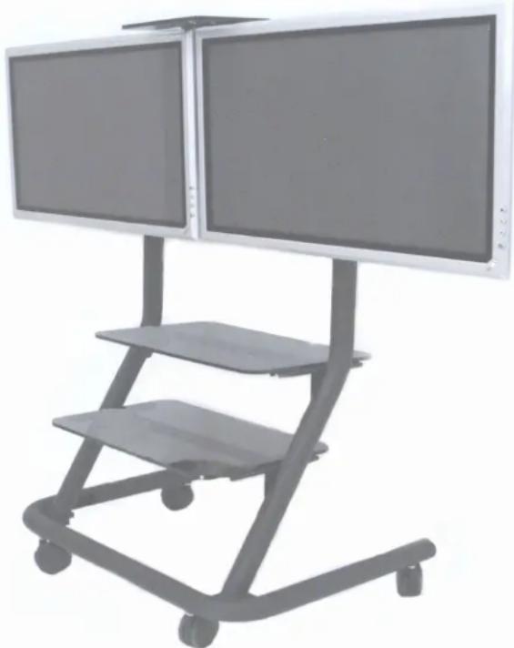
The PPD is a highly functional video conferencing solution. The cart provides agile mobility for two Large Flat Panel Displays, side-by-side, with a combined weight of up to 200 pounds. Optional equipment shelves and video conferencing accessory shelves can be easily added for a complete system.
Using Chief's exclusive ClickConnect™ Mounting System for easy installation, the cart provides stable mounting, quick release and optional security. Additionally, its streamline shape eliminates trip hazards and allows the display to roll smoothly up to a conference table
Large swivel casters with lock brakes, pitch adjustment, and cable management make the cart user friendly.
natural_image
Exterior view of a modern office building (no signage)BEFORE YOU BEGIN
- CAUTION: To prevent damage to the cart, which could affect or void the Factory warranty, thoroughly study all instructions and illustrations before you begin to install or operate the unit. Pay particular attention to the “Important Warnings and Cautions” on Page 2.
- The maximum weight to be installed on the PPD is 200 pounds (90.72 Kg).
- If you have any questions about this assembly, contact Chief Manufacturing at 1-800-582-6480 or 952-894-6280.
Chief® and ClickConnect™ are trademarks of Milestone AV Technologies. All rights reserved.

IMPORTANT WARNINGS and CAUTIONS!
WARNING: A WARNING alerts you to the possibility of serious injury or death if you do not follow the instructions.
CAUTION: A CAUTION alerts you to the possibility of damage or destruction of equipment if you do not follow the corresponding instructions.
- WARNING: Do not attempt to hang the plasma displays onto the cart alone. Always use two people to mount each display.
- WARNING: Always park the cart on a level surface. The locking wheels of the cart are not designed to hold the cart on an inclined surface.
- WARNING: Do not use the cart to transport your plasma displays on ramps or steep angles. The cart is designed to move on smooth, flat surfaces.
- CAUTION: Inspect the unit for shipping damage.
- CAUTION: Do not use cleanser or harsh cleaning agents on acrylic shelves.
CONTENTS
INSPECT PARTS BEFORE ASSEMBLY 3
OPTIONAL ACCESSORIES 3
TOOLS REQUIRED FOR INSTALLATION .... 3
PARTS 4
ASSEMBLE CART 6
MOUNT PLASMA DISPLAYS ON CART 8
INSPECT PARTS BEFORE ASSEMBLY
- Refer to Table 1 on page 4 and "PARTS" on page 4. Carefully inspect the parts for shipping damage.
- If any damage is apparent, call your carrier claims agent and do not continue with the assembly procedure until the carrier has reviewed the damage.
OPTIONAL ACCESSORIES
- Acrylic Shelf.
• Video Conferencing Shelf
TOOLS REQUIRED FOR INSTALLATION
- 7/16" and 3/4" wrench
- Allen wrenches
- Socket set with extension
NOTE: Other tools may be required depending on the method of installation.
PARTS
Table 1: Parts List
| REF | DESCRIPTION QTY REF DESCRIPTION QTY | |||||
| 10 | CASTERS, Front (No Locks) 2 120 LEG, Right 1 | |||||
| 20 | CASTERS, Rear (Locking) 2 130 SCREW, Cap, Button head, 1/4 | 20 x 5/8” | 28 | |||
| 30 | PLUG, Cap (hard plastic - use with base) | 2 | 140 | SCREW, Cap, Button head, 5/16-18 x 3/4” | 6 | |
| 40 | PLUG, Cap (slip on vinyl - use with legs) | 2 | 150 | WASHER, 1/4” | 2 | |
| 50 | PLATE, Face | 2 160 WRENCH, Allen, 3/16” (Not Shown) | 1 | |||
| 60 | FACEPLATE, Sides | 4 | ||||
| 70 | HEAD, Mounting (PPC Tilt Head) | 1 | ||||
| 80 | BRACKET, Dual Screen Mounting 1 | |||||
| 90 | SPREADER, Head tilt (viewed from inside) | 2 | ||||
| 100 | BASE, With corner supports | 1 | ||||
| 110 | LEG, Left | 1 | ||||
PARTS (CONT'D)
ASSEMBLE CART
NOTE: Read all instructions before assembly. Also, refer to Table 1 on page 4 and "PARTS" on page 4 for the numbers shown in parenthesis ( ).
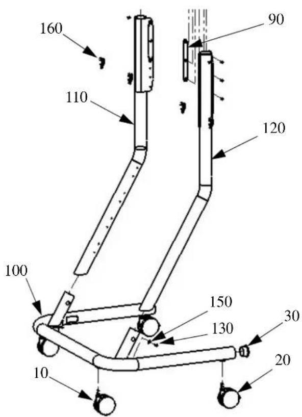
- Place base (100) upside down (see Figure 1).
a. Thread two regular casters (10) into the holes near the corner support posts in the base (front) as shown in Figure 1.
b. Thread two locking casters (20) into the holes at the end of the support posts for the base (front) as shown in Figure 1.
- Place base (100) upright on casters.
- Install legs for base (100) as follows:
a. Insert left leg (110) and right leg (120) into the support posts on the base. Make sure the mounting tabs face inward (see Figure 2).
b. Secure both legs using two washers (150) and two 1/4 x 1/2" screws (130).
c. Install cap plugs (30) in base (see Figure 3).
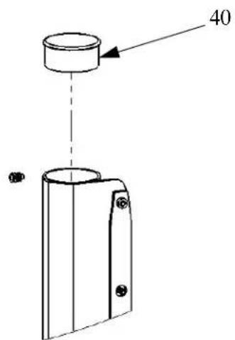
d. Install cap plugs (40) on top of left leg (110) and right leg (120). See Figure 4.
- Using two 1/4-20 x 5/8" button head screws (130), one on each side, secure the mounting head (70) to the top of the legs (110 and 120) of the cart (see Figure 4).
- Using four 1/4-20 x 5/8" button head screws (130), (two on each side), secure two tilt head spreaders (90), one per side (see Figure 4).
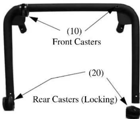
Figure 1. Install Casters
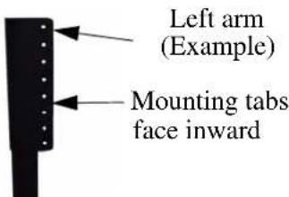
Figure 2. Turn Mounting Tabs Inward
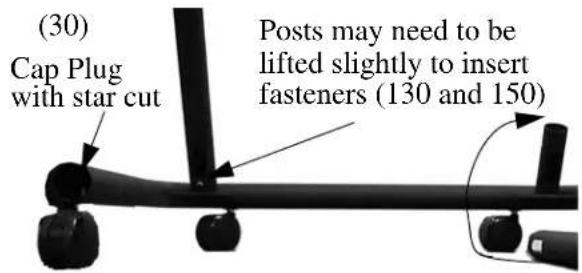
Figure 3. Install Legs
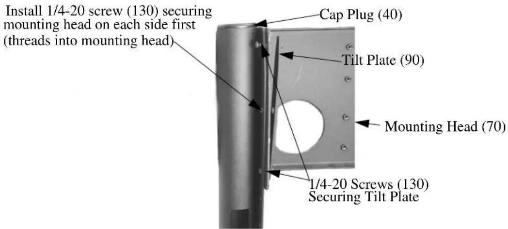
Figure 4. Install Mounting Head
ASSEMBLE CART (CONT'D)
- Adjust tilt head (70) to desired tilt by slightly loosening four 1/4-20x5/8" button head cap screws (130) securing tilt head spreaders (90), adjust tilt head to desired angle (0° to 7-1/2°), and tighten four 1/4-20x5/8" button head cap screws (130). See Figure 5).
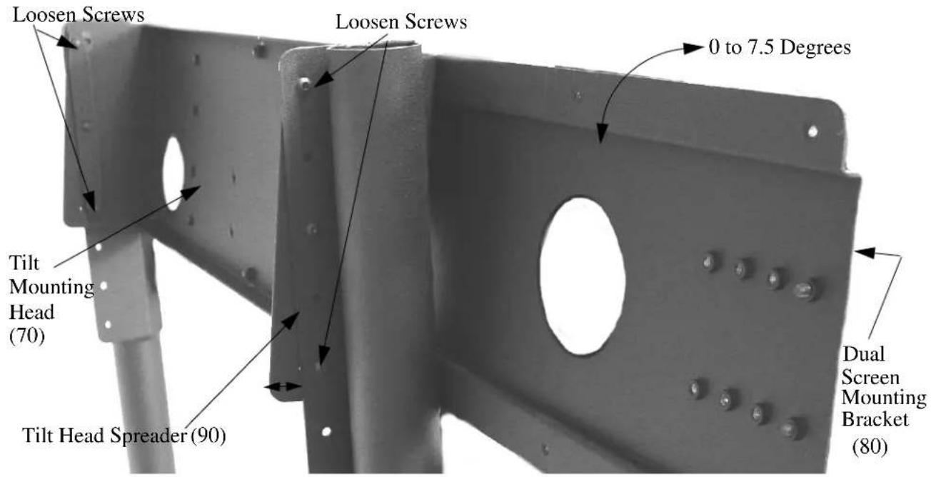
Figure 5. Adjust Tilt Mounting Head
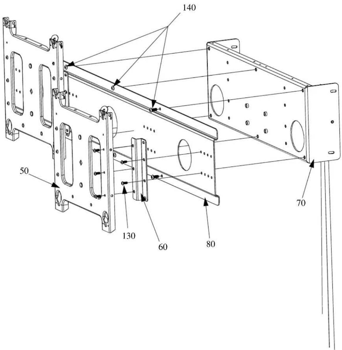
- Using six 5/16-18X3/4" screws (140), secure the dual screen mounting bracket (80) to the tilt mounting head (70) (see Figure 6).
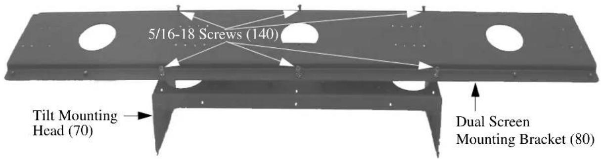
Figure 6. Attach Dual Screen Mounting Bracket to Mounting Head
MOUNT PLASMA DISPLAYS ON CART
- Measure the distance from the center of your display to its outermost edge.
NOTE: Make sure to leave some space between displays when mounted.
-
Using the measurement found in Step 1 and the faceplate (50) as a template, measure from the center of the dual screen mounting bracket (80) to find the correct mounting holes for your application (see Figure 7).
-
Secure each face plate (50) using four 1/4-20x5/8" screws (130) (see Figure 8).
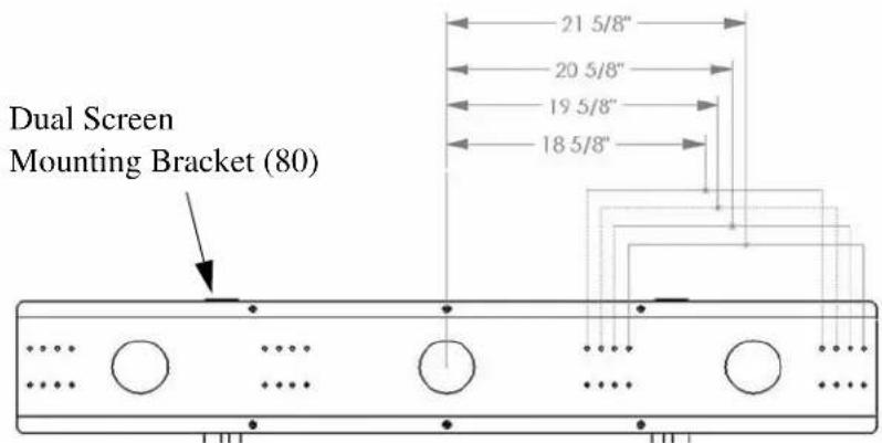
Figure 7. Dual Screen Mounting Bracket Head Measurements
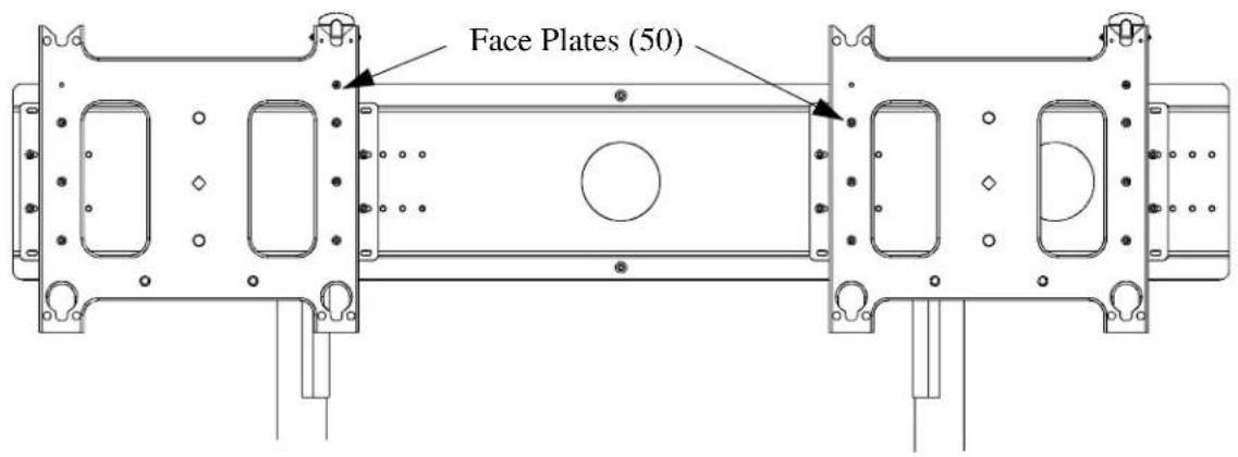
Figure 8. Dual Mounting Head with Face Plates Attached
MOUNT PLASMA DISPLAYS ON CART (CONT'D) To install display:
WARNING! Make sure cart wheels are locked before installing the display to the cart!
-
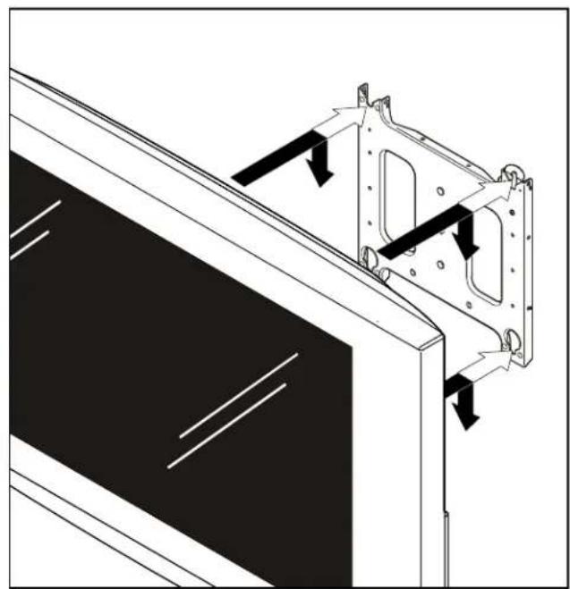
While supporting both sides of display, align four mounting buttons on display or interface bracket with four mounting holes in faceplate. (See Figure 9)
-
Lower display into place listening for audible "click" to ensure recessed area of mounting buttons are properly seated in lower area of mounting holes and ClickConnect mechanism has engaged. (See Figure 9) and (See Figure 10)
natural_image
Technical line drawing of a mechanical assembly with arrows indicating motion or force direction (no text or symbols)Figure 9 : Hang Display
NOTE: Holes are provided in the faceplate for use with a padlock or similar locking device, if desired. In addition, the pin and nut may be removed from the upper holes and moved to the lower holes for use as a more permanent locking device. (See Figure 10)
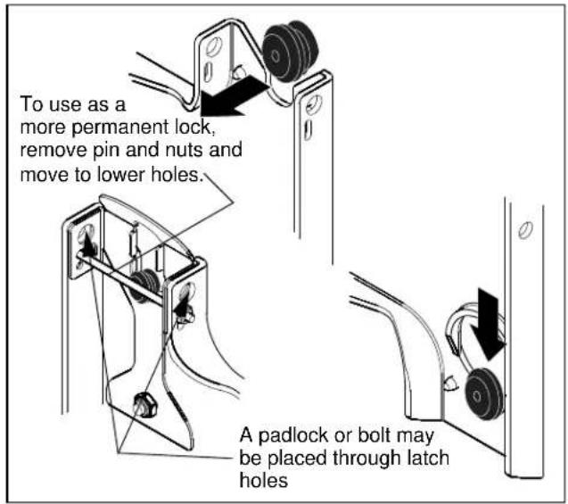
Figure 10: Secure Display
- INSTALLATION INSTRUCTIONS
- Plasma Presenters Dual Display Video Conferencing Cart (PPD-Series)
- BEFORE YOU BEGIN
- IMPORTANT WARNINGS and CAUTIONS!
- CONTENTS
- INSPECT PARTS BEFORE ASSEMBLY
- OPTIONAL ACCESSORIES
- TOOLS REQUIRED FOR INSTALLATION
- PARTS
- PARTS (CONT'D)
- ASSEMBLE CART
- ASSEMBLE CART (CONT'D)
- MOUNT PLASMA DISPLAYS ON CART
- MOUNT PLASMA DISPLAYS ON CART (CONT'D) To install display:
Brand : Chief
Model : PPD2000B
Category : Soundcard