
7716 tripod - Tripod DAVIS - Free user manual and instructions
Find the device manual for free 7716 tripod DAVIS in PDF.


| Product Type | Mounting Tripod for Weather Stations |
| Brand | Davis Instruments |
| Model | 7716 |
| Compatibility | Vantage Pro2 wireless and cabled ISS |
| Main Use | Supports Integrated Sensor Suite (ISS) for weather stations |
| Material | Steel tubing |
| Height Range | Adjustable via extension tubes up to approx. 2 m (6.5 ft) |
| Mounting Options | Deck or roof mounting with lag screws |
| Included Components | Tripod legs, long extension tube, anemometer extension tube, hardware kit (bolts, nuts, washers, U-bolts, saddle, pitch pads, cable ties) |
| Tools Required | Adjustable wrench, compass, drill with 3/16" or 5 mm bit |
| Torque Specification | 25 lb-ft (33.9 N·m) for U-bolt nuts; do not exceed |
| Lightning Protection | Follow local grounding recommendations; station has surge protection |
| Contact | Davis Technical Support: (510) 732-7814, support@davisnet.com |
| Manual Part Number | 7395.299, Rev. G (12/10/08) |
| Compliance | EC EMC Directive 2004/108/EC |
Frequently Asked Questions - 7716 tripod DAVIS
User questions about 7716 tripod DAVIS
0 question about this device. Answer the ones you know or ask your own.
Ask a new question about this device
Download the instructions for your Tripod in PDF format for free! Find your manual 7716 tripod - DAVIS and take your electronic device back in hand. On this page are published all the documents necessary for the use of your device. 7716 tripod by DAVIS.
USER MANUAL 7716 tripod DAVIS
For use with Davis's wireless and cabled Vantage Pro2 weather stations, the Mounting Tripod simplifies installation. The tripod supports the Integrated Sensor Suite (ISS) or other station, and features an adjustable foot pad which enables mounting on level surfaces or roof peaks.
Components
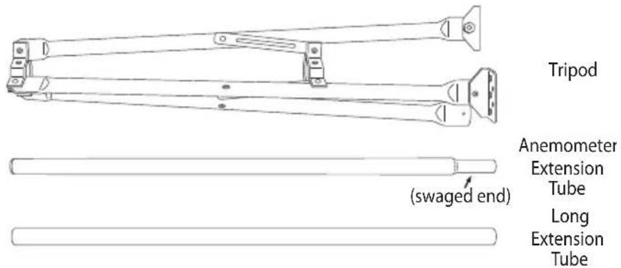
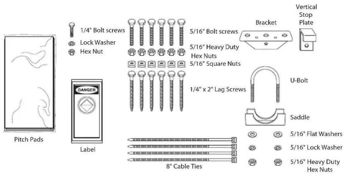
The Mounting Tripod includes the following poles and mounting hardware. Please make sure you have everything you need before beginning.
Poles
Hardware
Tools for Setup
- Adjustable wrench
- Compass or local area map
- Drill with 3/16" or 13/64" (5 mm) bit for the 1/4" lag screws
Tripod Assembly
Follow the instructions below to assemble the tripod.
- Unfold the tripod so the two foot pads which come pre-installed on the tripod legs are flat on the ground.
- Thread a hex nut almost all the way onto all six of the 5/16" bolts.
- Insert one of the 5/16" bolts into the hole in vertical stop plate.
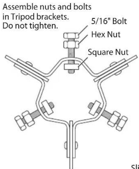
Use Vertical Stop Plate on one of the lower bracket bolts.
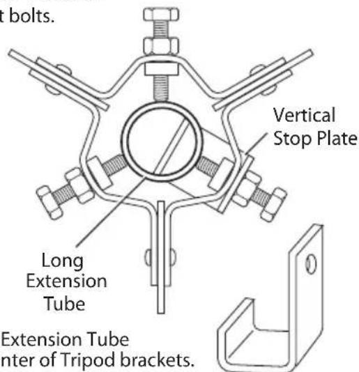
Slide Long Extension Tube through center of Tripod brackets. Tighten nuts and bolts.
- Insert the 5/16" bolt with vertical stop plate into one of the holes in the tripod's lower bracket and thread a square nut onto the end of the bolt, on the inside of the bracket.
Do not thread the square nut too far up the bolt.
- Repeat this procedure for the remaining 5/16" bolts. Place them into the holes in both the top and bottom tripod brackets, threading a square nut on the end of each bolt.
Do not thread the square nuts too far up the bolts.
- Insert the long extension tube into the tripod, sliding it through the brackets.
The vertical stop plate should keep the tube from sliding all the way through.
-
Secure the extension tube by tightening the square and hex nuts on the 5/16" bolts until the bolts hold the tube in place securely.
-
Attach the foot bracket to the tripod leg as shown.
Apply pitch pads to the bottom of the foot bracket and the two foot brackets that come pre-installed on the tripod.

Mounting the Tripod
Mount the tripod with long extension tube on the desired surface, as shown below. On the following pages are instructions for securing your sensor array or ISS onto the long extension tube.

Note: Any metal object may attract a lightning strike, including your weather station or tripod. If lightning strikes your station or strikes somewhere nearby, the station's internal electronics may suffer anywhere between little to extensive damage. The station itself has been designed with considerable surge protection, but to safeguard nearby equipment and structures, we recommend following local recommendations on properly grounding your installation.
For more information, contact your local lightning protection authority and/or refer to the following articles:
- MIL-HDBK-419A: Grounding, Bonding, and Shielding for Electronic Equipment and Facilities, 29 Dec 1987.
• National Fire Protection Association, 1997: Standard for Installation of Lightning Protection Systems, 1997 ANSI/NFPA 780, National Fire Protection Association, Quincy, MA. - NEC, National Electrical Code, 1996 Edition: National Fire Protection Information, Quincy, MA.
Attaching the Vantage Pro2 ISS to the Anemometer Extension Tube
For Vantage Pro2, the anemometer extension tube provided as part of the mounting tripod will be used to support the ISS, which does not come with its own pole. You can mount your ISS on this tube with both sides together or separate. For better access to the hardware securing the rain collector side, remove the rain collector cone by rotating it counter-clockwise and lifting it off of the base.
Mount your ISS and anemometer on the anemometer extension tube together or separately. See the illustration below for more information. Make sure the swaged end of the tube is pointing downward as you secure the ISS to it.
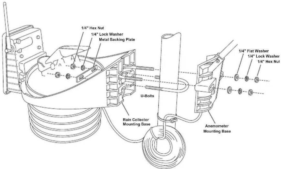
Option 1: Installing ISS and Anemometer Together
Remember when mounting both sides together that whichever side of the ISS is mounted first, the U-bolt from the opposite side ALSO must be placed around the pole before you tighten anything. (If it is not, there is no way to slide it in later.)
When both sides of the ISS are mounted together with the anemometer arm pointing north, the solar panel on the rain collector side is facing south. In the Northern Hemisphere, this positions the solar panel for optimal exposure to the sun. In the Southern Hemisphere, you will need to position the solar panel facing north for optimal sun exposure.
Try to install the ISS so the anemometer arm is aiming north. If the arm doesn't point north, re-orient the wind vane.
- Place the U-bolt for the anemometer around the pole so that its round end fits in the top groove of the side of the rain collector side's plastic mounting base. The groove is right above two large holes.
- While holding the mounting base of the rain collector against the pole, place the two ends of the remaining U-bolt around the pole and through the two holes in the base.
- Slide the metal backing plate over the bolt ends as they stick out over the rain collector base. Secure the metal backing plate with a lock washer and hex nut on each of the bolt ends as shown previously.
Note: Do not tighten the hex nuts yet. Leave the hex nuts loose to swivel the ISS base on the pole.
- The two ends of the anemometer's U-bolt should now be pointing away from the mounted rain collector side. Slide the anemometer's mounting base over the protruding bolt ends.
CAUTION: The anemometer cable should be routed in the anemometer base so that there is room to accommodate the U-bolt. Fold the anemometer cable deep into the anemometer base's recess to make sure the U-bolt does not pinch or rub the anemometer cable.
- Place a flat washer, a lock washer and a hex nut on each of the bolt ends as shown above. Do not tighten the nuts yet.
- Raise the ISS unit to the desired height on the pole and swivel it so the anemometer arm is pointing north.
- Using an adjustable wrench or 7/16" wrench, tighten all four hex nuts until the ISS is firmly fastened on the pole.
- Re-attach the rain collector cone by setting the cone back on the base so its latches slide downward into the latch openings on the base, then rotate the cone clockwise.
Option 2: Installing ISS and Anemometer Separately
- While holding the mounting base against the pole, place the two ends of a U-bolt around the pole and through the two holes in the base.
- Slide the metal backing plate over the bolt ends as they stick out toward the rain collector cone. Secure the metal backing plate with a washer, a lock washer, and a hex nut on each of the bolt ends. Do not tighten the nuts yet.
-
For the wireless ISS, swivel the ISS base so the solar panel is facing south (in the Northern Hemisphere), or north (in the Southern Hemisphere).
-
Tighten the hex nuts using an adjustable wrench or 7/16" wrench.
- Re-attach the rain collector cone.
- Set the cone back on the base so its latches slide downward into the latch openings on the base. Rotate the cone clockwise.
- While holding the mounting base against the pole, place a U-bolt around the pole and through the two holes in the base.
- Place a flat washer, a lock washer and a hex nut on each of the bolt ends.
- Swivel the anemometer until the arm is pointing north. See the Vantage Pro2 ISS Installation Manual for more information about orienting the wind vane to point north.
- Using an adjustable wrench or 7/16" wrench, tighten the hex nuts.
Securing the ISS on the Tripod
Now the ISS is firmly attached to the anemometer extension tube.
- Insert the swaged end of the anemometer extension tube down into the long extension tube in tripod.
- Consulting a compass or local map, turn assembly until the anemometer arm points directly north.
- Place the U-bolt provided with the tripod around the tubes where they overlap. Secure the saddle onto the U-bolt with the flat washers, lock washers, and hex nuts as shown.
- Tighten the hex nuts quite firmly, until the U-bolt begins to dent the tubing slightly. We recommend
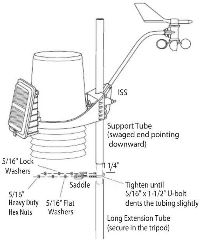
the use of a torque wrench with 25 lb-ft of pressure to fasten the hex nuts. The support tube should be crimped on the extension tube securely to prevent any rocking or rotating.
Note: Do not use over 25 lb-ft torque wrench, it may damage the U-bolts.
Attaching a Complete System Shelter
Install a complete system shelter or multi-purpose shelter the same way you would an ISS assembly.
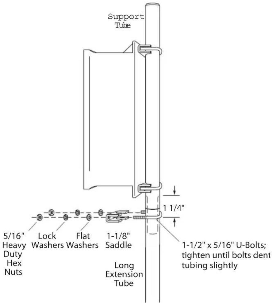
- We recommend the use of a torque wrench with 25 lb-ft of pressure to fasten the hex nuts.
The support tube should be crimped on the extension tube securely to prevent any rocking or rotating.
Note: Do not use over 25 lb-ft torque wrench, it may damage the U-bolts.
Contacting Davis Instruments
If you have questions about installing your weather system on a tripod or encounter problems installing a weather station on the tripod, please contact Davis Technical Support.
Note: Please do not return items to the factory for repair without prior authorization.
(510) 732-7814 – Technical Support phone, Monday – Friday, 7:00 a.m. – 5:30 p.m. Pacific Time.
(510) 670-0589 – Technical Support Fax.
support@davisnet.com – E-mail to Technical Support.
info@davisnet.com – General e-mail.
www.davisnet.com – Download manuals and specifications from the Support section. Watch for FAQs and other updates. Subscribe to the e-newsletter.
Product Number: #7716
Davis Instruments Part Number: 7395.299 Mounting Tripod Kit Installation Manual Rev. G Manual (12/10/08)
This product complies with the essential protection requirements of the EC EMC Directive 2004/108/EC.
© Davis Instruments Corp. 2008. All rights reserved.
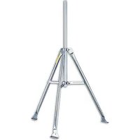
Brand : DAVIS
Model : 7716 tripod
Category : Tripod