
V-5324004 - Intercom Valcom - Free user manual and instructions
Find the device manual for free V-5324004 Valcom in PDF.


| Product Type | Intercom |
| Brand | Valcom |
| Model | V-5324004 |
| Dimensions (H x W x D) | 4.7 x 3.1 x 1.2 inches (120 x 80 x 30 mm) |
| Weight | 0.44 lb (200 g) |
| Power Supply | 12V DC, 100 mA |
| Audio Type | Full-duplex, hands-free |
| Number of Stations | 1 door station, 1 indoor unit |
| Wiring Type | 2-wire analog |
| Main Functions | Audio communication, door release, call button |
| Door Release Output | Electric strike compatible (12V, 1A max) |
| Mounting | Wall-mounted (indoor unit) |
| Operating Temperature | 32°F to 104°F (0°C to 40°C) |
| Maintenance | Wipe with a dry, soft cloth; avoid liquids |
| Safety | Low voltage, CE compliant |
| Spare Parts | Available from Valcom authorized dealers |
| Repairability | Limited; replace unit if defective |
| Warranty | 1 year limited |
Frequently Asked Questions - V-5324004 Valcom
User questions about V-5324004 Valcom
0 question about this device. Answer the ones you know or ask your own.
Ask a new question about this device
Download the instructions for your Intercom in PDF format for free! Find your manual V-5324004 - Valcom and take your electronic device back in hand. On this page are published all the documents necessary for the use of your device. V-5324004 by Valcom.
USER MANUAL V-5324004 Valcom
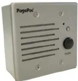
The Station Door Phone is specifically designed to communicate with a telephone system that provides Primeline, Off-hook ring-down, Hotline and Elevator Call capabilities.
The Station Door Phone connects to a standard telephone system analog station port to allow the caller at the door speaker to have a two-way conversation with someone inside the building. The weather resistant enclosure is ideal for indoor or outdoor environments.
SPECIFICATIONS FEATURES
- Push Button - to initiate signaling
• LED - lights up to indicate activation - Two-way handsfree voice communication
• Volume Control - adjusts speaker volume - No external power required
- Stainless steel faceplate with tamper resistant hardware
- Weather resistant gang box included
• VOX circuit - to turn unit off with lack of voice activity - Turns off if button is depressed a second time
- Alert tone emits from speaker when accessed
Dimensions/Weight
Unfinished (without the gang box)
- 4.63" W x 4.63" H x 1.75" D (11.76cm x 11.76cm x 4.45cm 0.72 lbs. (0.32 kg)
Finished (with the gang box)
- 4.75" W x 4.75" H x 2.50" D (12.07cm x 12.07cm x 6.35cm) 1.52 lbs. (0.68 kg)
natural_image
Exterior view of a PagePac device with ventilation grilles and a control knob (no readable text or symbols)OPERATION
Off-Hook Ring-down, Hotline, Primeline
The Station Door Phone operates much like a telephone without a dial-pad. It connects to an analog station port on a telephone system. When the Station Door Phone push button is pressed, this unit provides an off-hook condition to the telephone system analog station port, the faceplate LED lights and an alert tone beeps at the speaker.
Some telephone systems provide a programmable auto-dial/ring-down feature. When used with these telephone systems, the phone system will automatically dial a telephone number (preprogrammed into the phone system software) when the Station Door Phone push button is pressed. The person answering the ringing phone inside is automatically connected to the caller at the Station Door Phone.
To call the Station Door Phone from a telephone, dial the extension number, just as you would dial a telephone extension.
NOTE: See Figure 5 for normal default Dip Switch settings.
Auxiliary Alert
The Station Door Phone can be used to activate an Auxiliary Alert device (such as a door bell or chime) instead of ringing a telephone.
VOX Operation
The Station Door Phone is equipped with a VOX (voice activated switch) circuit. This feature is provided to automatically drop communications to the door speaker when there is no audio detected, for more than 24 seconds, from the telephone extension within the building. Visitors talking into the door speaker will not affect the VOX circuit.
INSTALLATION
There are two surface mount methods to secure the Station Door Phone to a wall. The first method utilizes mounting brackets. The gang box mounting brackets (included) can be screwed to the back plate so they protrude out the sides of the box. Position the screws through the bracket holes and secure the box to the wall.
Another method to attach the gang box to the surface of a wall is to drill mounting holes (4) directly into the back of the box. Position the screws through the inside of the box and secure to the wall.
NOTE: All conduit and closure plug connections should be adequately sealed (i.e., pipe joint compound) for wet location installations.
Do not allow conduit to protrude into rear opening of outlet box to avoid interference with Station Door Phone. Wire length should be kept to 6 inches to avoid interferences during installation. For maximum protection from ESD or lightning, connect the outlet box to earth ground via the conduit.
CONNECTIONS
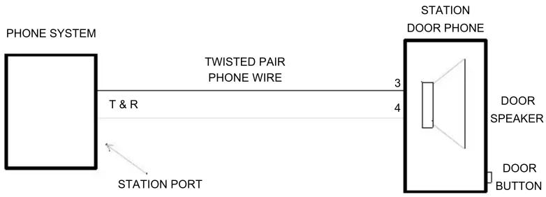
The Station Door Phone back panel has two sets of terminals; one set is labeled "ALERT", and the other labeled "TIP/RING" (see Figure 1). The "TIP/RING" terminals that connect to your telephone system must use twisted pair phone wire. See Figure 2 for wiring diagram. Follow steps below:
NOTE: Check National Electrical Code and applicable local codes and ordinances for exact wiring requirements for your area.
-
Loosen each of the terminal block screws and insert exposed wire ends into appropriate terminal block locations. Tighten screws and ensure wire connections are correct before continuing.
-
Place the dip switch in the position shown in Figure 5 (factory default setting). Program your telephone system for the phone number(s) to be called when the Station Door Phone button is activated.
Dip Switch Features
(Power must be cycled after dip switch settings change).
Guard Mode - Alerts the guard with the second DPDT (Double Pole, Double Throw) contacts and disables off-hook control.
Elevator Mode - Depressing button activates the unit and can not be turned off (on-hook) and disables VOX timeout.
Push On-Push Off Mode - Depress button to activate, press again to cancel. 24 second VOX timeout. Factory default position.
Line Flash Ring Mode - Depress button to activate. Press again to flash (800mS) to signify "telephone" host system to re-ring.
Push On Only Mode - Depressing button activates unit and can not be turned off, unit returns on-hook status after 24 second timeout period.
Momentary Page Mode - Push to activate.
NOTE: Total length of wire from the door phone unit to the telephone system is not to exceed 1500 feet.
- Connect the Station Door Phone wires to the designated station port on the telephone system.
- Test the system by having an assistant call the designated extension number of the Station Door Phone.
Adjust the speaker volume (see Figure 3) to an appropriate level.
- Place poly-fil pad in designated position for good sound quality (see Figure 3).
- Secure Station Door Phone and faceplate to double-gang outlet box with four mounting screws (included).
INSTALLATION INSTRUCTIONS CUSTOMER PROVIDED OR EXISTING DOOR ALERT (SIGNALING UNIT)
These instructions apply to the use of a customer provided auxiliary alert or an existing door alert (signaling) unit.
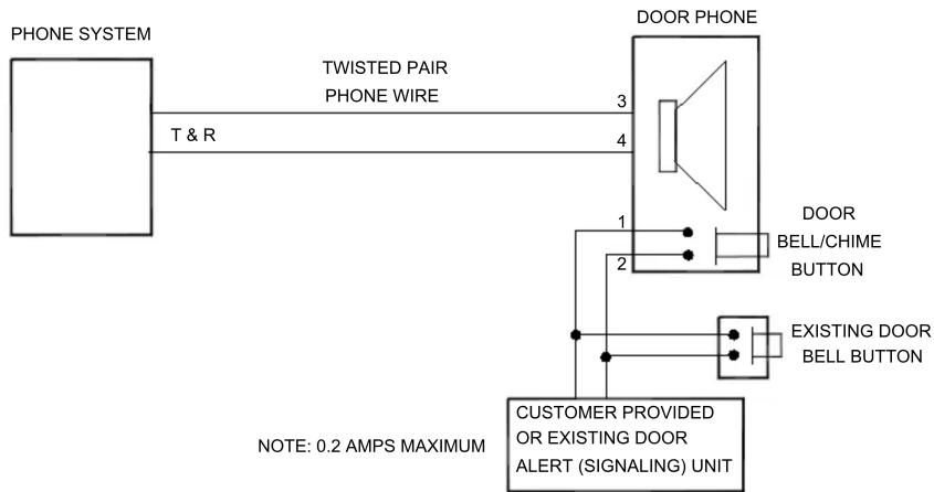
- Connect Station Door Phone to existing door alert push button so that existing button is in parallel with Station Door Phone Terminals 1 and 2 (see Figure 2).
NOTE: While Station Door Phone button or existing door bell button is depressed some types of alerting devices will continue to sound or operate.
If desired, the existing door bell button can be removed thus allowing the Station Door Phone button to replace the function of the existing door bell button. Connect wires from existing door bell button to Terminals 1 and 2 on the Station Door Phone (see Figure 4).
NOTE: When using Auxiliary Alert option, all four wires must be connected.
TECHNICAL ASSISTANCE
When calling, have a VOM and a telephone test set available and call from the job site. Call (540) 563-2000 and press 1 for PagePac Technical Support or visit our websites at http://www.pagepac.com and www.valcom.com.
Should repairs be necessary, attach a tag to the unit clearly stating company name, address, phone number, contact person and the nature of the problem. Send the unit to:
Valcom, Inc.
PagePac® Repair Dept.
5614 Hollins Road
Roanoke, VA 24019-5056
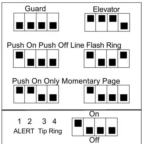
FIGURE 1. STATION DOOR PHONE TERMINAL LOCK/DIP SWITCHES
flowchart
graph LR
    A["PHONE SYSTEM"] -->|T & R| B["TWISTED PAIR PHONE WIRE"]
    B -->|3| C["STATION DOOR PHONE"]
    C -->|4| D["DOOR SPEAKER"]
    D --> E["DOOR BUTTON"]
    F["STATION PORT"] --> A
FIGURE 2. STATION DOOR PHONE WIRING DIAGRAM
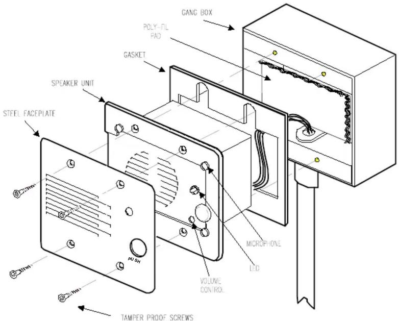
FIGURE 3. ATTACH STATION DOOR PHONE AND FACEPLATE
flowchart
graph LR
    A["PHONE SYSTEM"] -->|T & R| B["TWISTED PAIR PHONE WIRE"]
    B --> C["DOOR PHONE"]
    C --> D["CUSTOMER PROVIDED OR EXISTING DOOR ALERT (SIGNALING) UNIT"]
    D --> E["DOOR BELL/CHIME BUTTON"]
    D --> F["EXISTING DOOR BELL BUTTON"]
    style A fill:#f9f,stroke:#333
    style B fill:#ccf,stroke:#333
    style C fill:#cfc,stroke:#333
    style D fill:#fcc,stroke:#333
    style E fill:#ffc,stroke:#333
    style F fill:#fcc,stroke:#333
FIGURE 4. WIRING DIAGRAM FOR CUSTOMER PROVIDED OR EXISTING ALERTERS
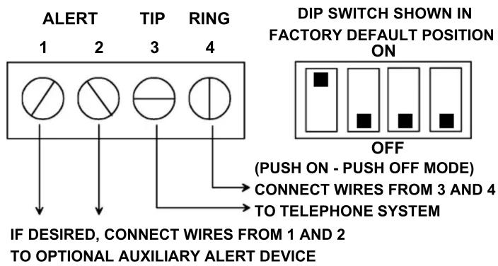
FIGURE 5. STATION DOOR PHONE BACK PANEL CONNECTIONS
Brand : Valcom
Model : V-5324004
Category : Intercom