
T9 Value - Sacoche pour ordinateur Sharkoon - Free user manual and instructions
Find the device manual for free T9 Value Sharkoon in PDF.


| Product Type | ATX Mid Tower PC Case |
| Model | Sharkoon T9 Value |
| Dimensions (L x W x H) | 475 x 200 x 440 mm |
| Weight | Approximately 6.6 kg |
| Form Factor Support | ATX, Micro-ATX, Mini-ITX |
| Drive Bays (External 5.25") | 9 |
| Drive Bays (Internal 3.5") | Via 5.25" to 3.5" adapter |
| Expansion Slots | 7 |
| Front I/O (Value Edition) | 1x USB 3.0, 3x USB 2.0, 2x Audio (Headphone + Mic) |
| PSU Support | Standard ATX PSU (not included) |
| Pre-installed Fans | 2x 120mm Front (LED, 3-pin + 4-pin), 1x 120mm Rear (LED, 3-pin + 4-pin) |
| Fan Mounts (Optional) | Side panel: 2x 120mm; Rear: 1x 80mm or 120mm |
| Water Cooling Support | 2 openings for external radiators |
| Material | Steel chassis, plastic front bezel |
| Side Panel | Acrylic window (Value edition) |
| Motherboard Mounting Panel | With cutout for CPU cooler backplate, cable management system |
| Drive Mounting Method | Tool-free quick fasteners for optical drives, screws for HDD/SSD |
| Included Accessories | Screw kit, standoffs, washers, lock attachment, speaker, 5.25" bezel with 3.5" opening |
| Cleaning Instructions | Use a dry cloth to wipe exterior; avoid liquid cleaners near electronics |
| Safety Notes | Keep away from moisture; ensure proper grounding to avoid static damage |
Frequently Asked Questions - T9 Value Sharkoon
User questions about T9 Value Sharkoon
0 question about this device. Answer the ones you know or ask your own.
Ask a new question about this device
Download the instructions for your Sacoche pour ordinateur in PDF format for free! Find your manual T9 Value - Sharkoon and take your electronic device back in hand. On this page are published all the documents necessary for the use of your device. T9 Value by Sharkoon.
USER MANUAL T9 Value Sharkoon
natural_image
Exterior view of a black desktop computer tower case with visible drive bays and ventilation slots (no text or symbols)Content
- Features
- Package content
- The case at a glance
- Installation of a mainboard
- Installation of a PSU
- Installation of a HDD
- Installation of an optical device
- Installation of a 3.5" device
- Installation of an add-on card
- The pre-installed fans (Value edition only)
- Installation of additional fans / optimized airflow
Dear customer!
Congratulations for purchasing this premium quality SHARKOON product.
For a long life time and to take full advantage of this product we recommend you to read this manual completely.
Have a good time with our product!
- ATX case
- 9x 5.25" drive bays
• Front I/O (Value edition): 1x USB3.0, 3x USB2.0 and 2x audio
• Front I/O (Economy edition): 4x USB2.0 and 2x audio
• 7 slots for add-on cards
- Mesh front panel
- Quick fasteners for optical drives, mainboard mounting panel with installation opening for coolers
• 2 openings for water cooling
• Cable management system
- Fan configuration:
| Value edition Economy edition | ||
| Case front | 2x 120 mm fan with LED as well as 3-pin and 4-pin connector (pre-installed) | 1x 120 mm fan (optional) |
| Side panel Acrylic 2 | 2x 120 mm fans (optional) | |
| Rear panel | 1x 120 mm fan with LED as well as 3-pin and 4-pin connector (pre-installed) | 1x 80 mm or 120 mm fan (optional) |
- Dimensions: 475 × 200 × 440 ~mm (L × W × H)
• Weight: \~6.6 kg
2. Package content
• PC case "T9 Value" or "T9 Economy"
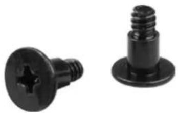
- Screw kit:
 | 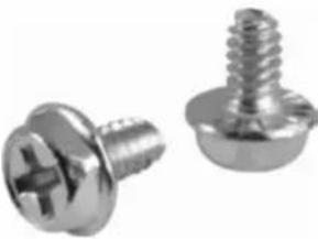 | 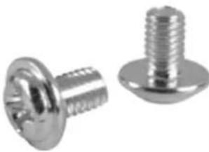 | 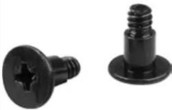 |
| Screws for mainboard mounting | Screws for PSU mounting | Screws for drive mounting (3.5" and 5.25") | Screws for HDD mounting |
- Accessory kit:
| Stand-offs for mainboard Washers | Lock attachment (A) and speaker (B) |
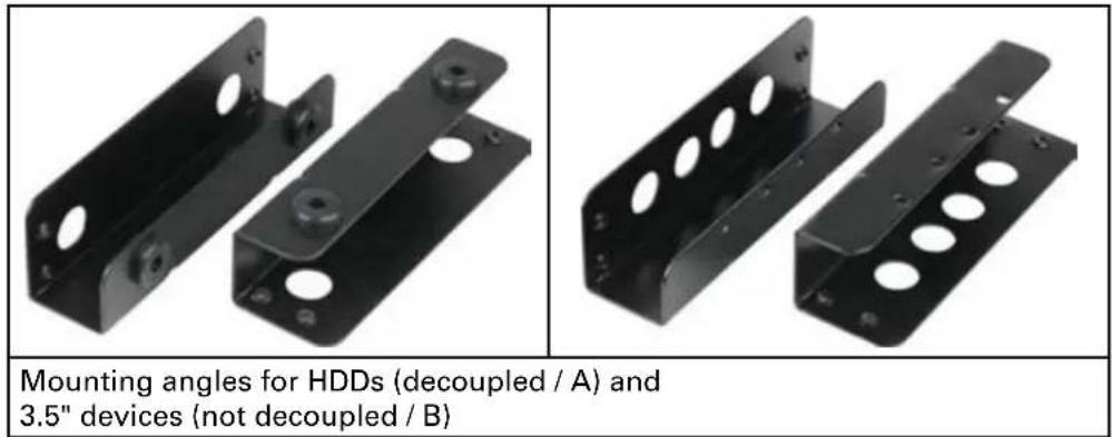
| Quick fasteners for optical drives | 5.25" bezel with 3.5" opening |
Note:
If you are missing any of the items listed above, please contact our customer service immediately:
support@sharkoon.com (Germany and Europe)
support@sharkoon.com.tw (international).
3. The case at a glance
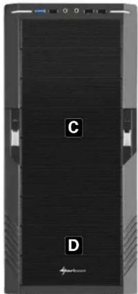
Front view
natural_image
Front view of a black server rack with labeled ports (C and D) and a Huawei logo at the bottom right corner.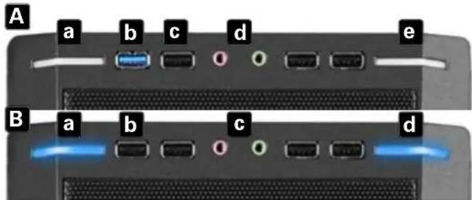
A - Front I/O (Value edition): a - Power LED b - USB3.0 connector c - USB2.0 connectors
d - Audio connectors e - Power and HDD LED
B - Front I/O (Economy edition): a - Power LED b - USB2.0 connectors c - Audio connectors d - Power and HDD LED
C - 5.25" drive bays D - covered: pre-installed 120 mm fans (Value edition)
Side view (closed/left)
natural_image
Black desktop computer tower with ventilation slots and drive bays (no visible text or labels)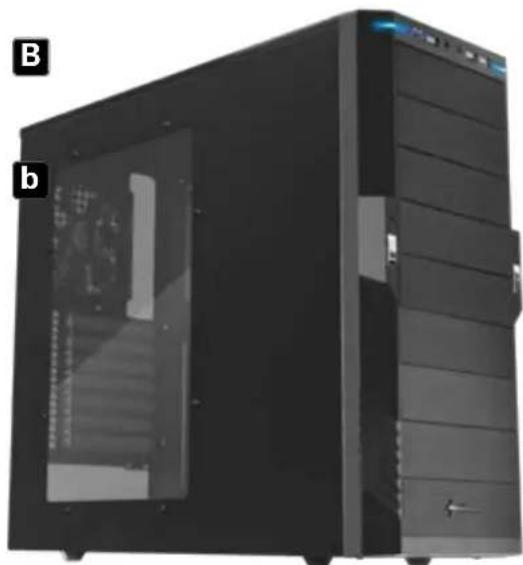
natural_image
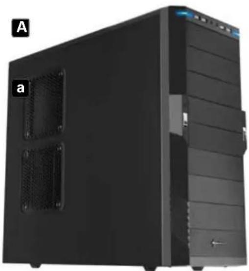
Black desktop computer tower case with visible drive bays and ventilation slots (no text or symbols)A - T9 Economy edition a - Brackets for two 120 mm fans
B - T9 Value edition b - Acrylic side panel
Side view (opened/left)
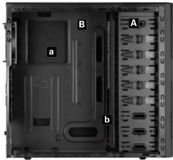
A - Drive bays for 5.25" devices
B - Mainboard mounting panel with:
a - Installation opening for CPU coolers and
b - Cable management system
Back side view
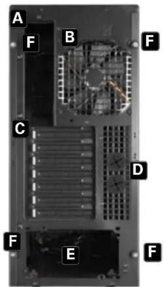
A - Opening for I/O shield
B – Pre-installed 120 mm fan (Value edition)
C - Slot bezels
D – Openings for water cooling
E - PSU bracket
F - Thumb screws
Bottom view
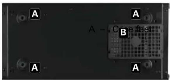
B – Air intake for PSU
Note:
For more information on how to install the intended devices, refer to their respective documents.
4. Installation of a mainboard
-
Open the case by loosening the thumb screws on the case's back side and removing the left side panel. Lay down the case sidewise on an even surface.
-
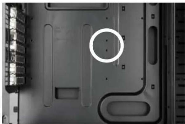
The mainboard's mounting panel inside the case provides various drillings to fix the stand-offs (fig. 1).
natural_image
Close-up of a computer monitor rear panel with a white circle highlighting a specific area (no text or symbols visible)fig. 1
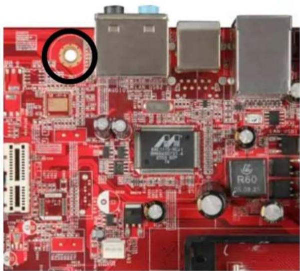
The mainboard contains special screw openings (fig. 2).
natural_image
Close-up of a red printed circuit board with various electronic components and a circular inset highlighting a specific component (no readable text or symbols)fig. 2
Place the mainboard to the mounting panel. A stand-off must be screwed into every drilling of the mounting panel visible through the mainboard's screw openings.
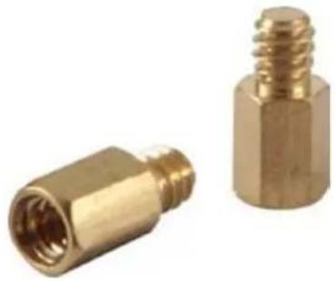
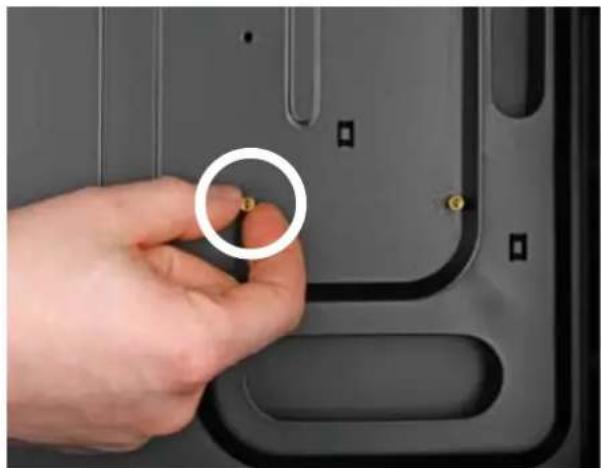
- Remove the mainboard and screw the stand-offs into the respective drillings of the mounting panel (fig. 3).
natural_image
Two brass mechanical connectors shown from different angles (no text or symbols visible)(Stand-offs)
natural_image
Close-up of a hand holding a small circular component on a dark gray laptop back panel (no text or symbols visible)fig. 3
- Press the I/O shield (delivered with the mainboard) into the I/O shield opening in the case's back side.
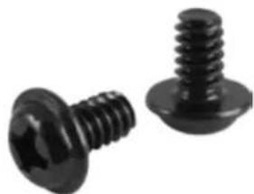
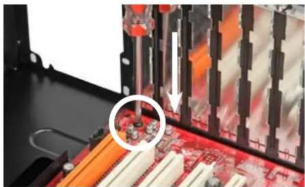
- Place the mainboard back onto the stand-offs and screw the mainboard to them (fig. 4).
natural_image
Two black screw fasteners with threaded caps, shown from different angles (no text or symbols visible)(Screws for mainboard mounting)
natural_image
Close-up of a computer motherboard with a highlighted CPU socket and a magnified inset showing the next component (no text or symbols visible)fig. 4
- Plug the connectors of the case's front bezel to the respective connectors of the mainboard (also refer to your mainboard's manual for further information).
Note:
The eSATA cable connected to the front eSATA connection should not exceed 50 cm of length otherwise transmission errors may occur! With premium quality eSATA cables this maximum length may be exceeded.
5. Installation of a PSU
- Set up the case in front of you and put the PSU from the inside against the PSU bracket on the case's back side (fig. 5).
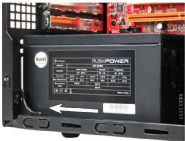
fig. 5
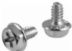
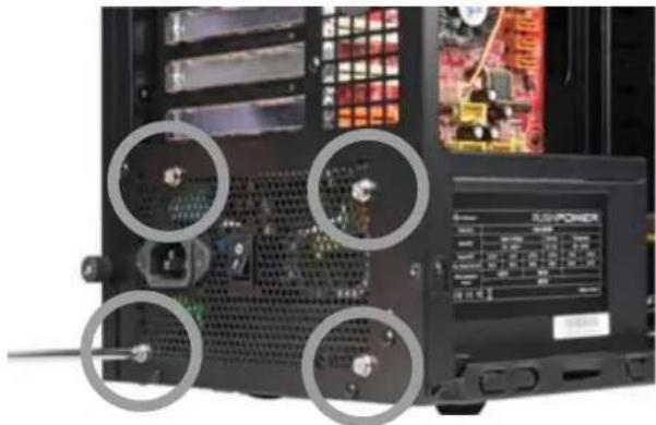
- Screw the PSU to the case from the outside (fig. 6).
natural_image
Two metallic screw fasteners, one with a cross-shaped end and the other with threaded screw (no text or symbols visible)(Screws for PSU mounting)
natural_image
Close-up of a computer tower case with visible circuit board and power monitor, showing four circular annotations highlighting internal components (no readable text or symbols)fig. 6
6. Installation of a HDD
- Remove the case's right side panel.
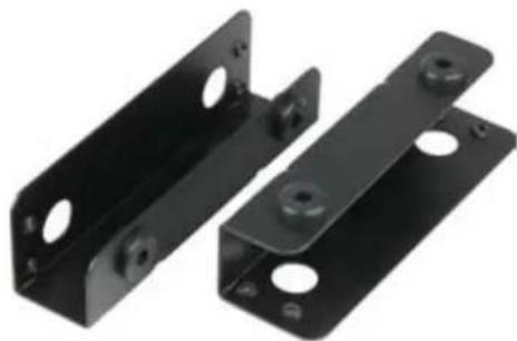
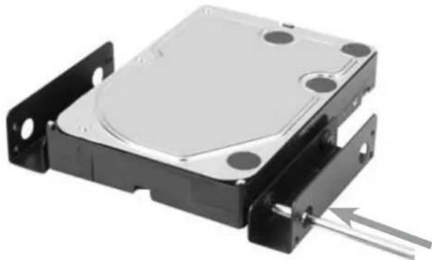
- Attach the decoupled mounting angles to the HDD from both sides (fig. 7).
natural_image
Two black plastic screw fasteners with threaded caps, shown from different angles (no text or symbols visible)(Screws for HDD mounting)
natural_image
Two black metal bracket plates with mounting holes and bolt holes (no text or symbols visible)(Decoupled mounting angles)
natural_image
Close-up of a hard disk drive housing with mounting brackets and a metallic casing (no visible text or symbols)fig. 7
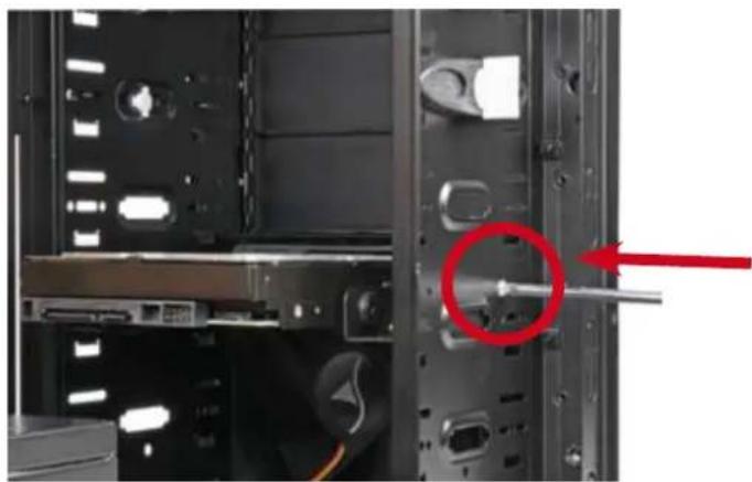
- Slide the HDD with attached mounting angles into the case's respective drive bay and screw it from both sides (fig. 8).
natural_image
Interior view of a computer tower case showing internal components and a red circle highlighting a specific part (no text or symbols visible)fig. 8
- Connect the HDD to the power supply and the mainboard.
7. Installation of an optical device
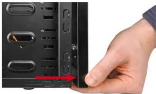
- Remove the case's front panel by gently dragging it towards you (fig. 9).
natural_image
Close-up of a hand inserting a USB drive into a black server rack (no text or symbols visible)fig. 9
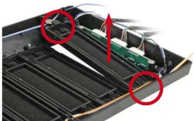
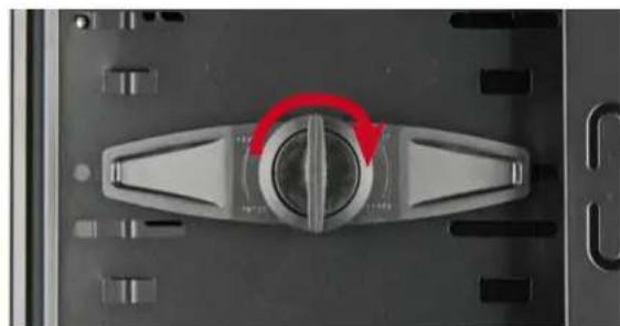
- Dismantle the 5.25" front bezel from the mounting bay in which you intend to install the drive by loosening its screws and pushing the bezel to the inside (fig. 10). Remove the quick fasteners (fig. 11).
natural_image
Interior view of an electronic device showing exposed circuit boards and wiring, with two red circles highlighting specific components (no text or symbols visible)fig. 10
natural_image
Close-up of a mechanical component with a red circular arrow indicating rotation (no text or symbols visible)fig. 11
(Carefully take out an optionally present metal bezel covering the 3.5" drive bay by using a gripper.)
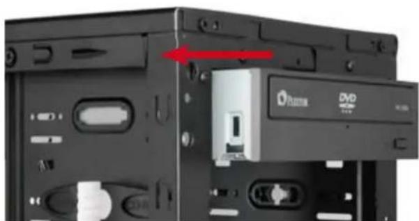
- Slide the optical drive into the case's drive bay (fig. 12).
natural_image
Close-up of a CD-ROM drive showing internal components and a red arrow indicating a specific portion (no text or symbols visible)fig. 12
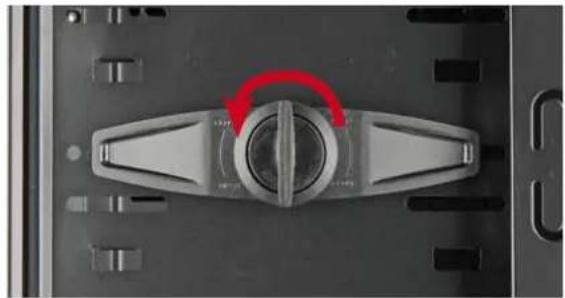
- Attach the optical device from both sides using the quick fasteners (fig. 13).
natural_image
Close-up of a mechanical switch component with a red curved arrow indicating rotation (no text or symbols visible)fig. 13
Note:
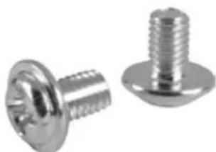
If you intend to transport the case we recommend securing (additionally) the installed drives:
natural_image
Two metallic screw fasteners with threaded caps, shown from different angles (no text or symbols visible)Screws for 5.25" drive mounting
- Connect the optical drive to the power supply and the mainboard. (Put the front bezel back onto the case.)
8. Installation of a 3.5" device
(1. Remove the case's front panel by gently dragging it towards you.)
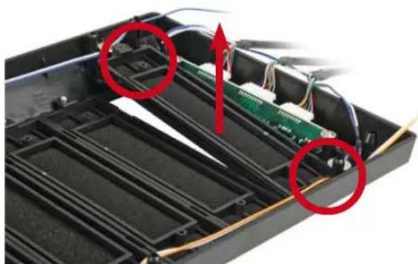
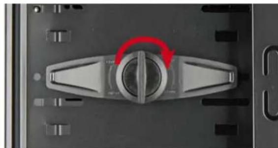
2. Dismantle the 5.25" front bezel from the mounting bay in which you intend to install the drive by loosening its screws and pushing the bezel to the inside (fig. 14). Remove the quick fasteners (fig. 15).
natural_image
Interior view of an electronic device showing a green circuit board and exposed wiring, with red circles highlighting areas of interest (no text or symbols present)fig. 14
natural_image
Close-up of a mechanical switch component with red circular arrow indicating rotation (no text or symbols)fig. 15
(In case there is a metal bezel covering the drive bay, remove it by using a gripper.)
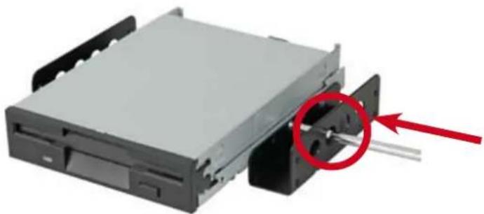
- Screw the mounting angles to the 3.5" device from both sides (fig. 16).
natural_image
Close-up of a CD-ROM drive with a red circle highlighting a mechanical component (no text or symbols visible)fig. 16
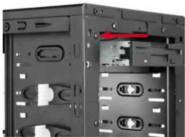
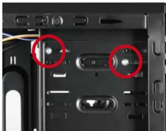
- Slide the 3.5" device with attached mounting rails into the case's drive bay (fig. 17) and screw it to the drive bay from both sides (fig. 18).
natural_image
Interior view of a computer tower case showing drive bays and a red arrow indicating a component (no text or symbols visible)fig. 17
natural_image
Close-up of a computer tower case showing internal components with red circles highlighting specific parts (no text or symbols visible)fig. 18
- Connect the 3.5" device to the power supply and the mainboard.
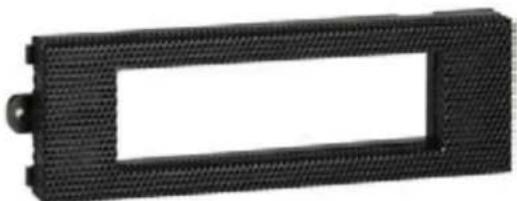
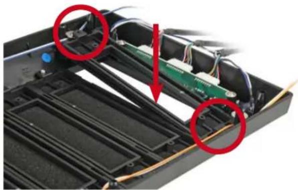
- Screw the 5.25" bezel with 3.5" opening into the front panel (fig. 19) and place it back onto the case.
natural_image
Black rectangular object with a textured border and central hole, resembling a mechanical or electronic component (no text or symbols visible)5.25" bezel with 3.5" opening
natural_image
Interior view of an electronic device showing internal components and wiring, with red circles highlighting specific areas (no text or symbols visible)fig. 19
9. Installation of an add-on card
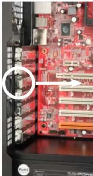
- Remove the slot bezel's fixation screw and take away the slot bezel (fig. 20).
natural_image
Interior view of a computer motherboard showing red circuit board and slots, with a magnified inset highlighting a specific component (no text or symbols visible)fig. 20
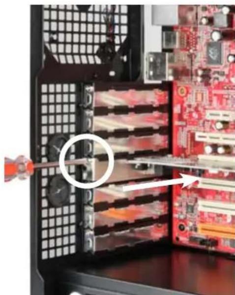
- Insert the add-on card into the mainboard's respective slot and fix it to the case by re-attaching the fixation screw (fig. 21).
natural_image
Interior view of a computer motherboard showing CPU socket, drive slots, and circuit board (no text or symbols visible)fig. 21
10. The pre-installed fans (Value edition only)
- The pre-installed 120 mm front fans provide a 4-pin PSU connector and a 3-pin mainboard plug.
- Connect one of both plugs to either the respective PSU or (to control the fan speed via the mainboard) the matching mainboard connector.
11. Installation of additional fans / optimized airflow
- Place the fan against the respective bracket from the inside (e.g. in the side panel).
- Screw the fan to the attachment from the outside.
Note:
While installing fans make sure that (cool) air is taken in on the case's front side/bottom and blown out on its back side/top. The PC components with the highest heat development should be placed directly within the airflow.
Legal disclaimer:
As a continuing policy of product improvement at SHARKOON, the design and specifications are subject to change without prior notice. National product specifications may vary.
All rights reserved especially (also in extracts) for translation, reprinting, reproduction by copying or other technical means. Infringements will lead to compensation.
All rights reserved especially in case of assignation of patent or utility patent. Means of delivery and technical modifications reserved.
Disposal of your old product
Your product is designed and manufactured with high quality materials and c which can be recycled and reused.

When this crossed-out wheeled bin symbol is attached to a product, it means the product is covered by the European Directive 2002/96/EC.
Please be informed about the local separate collection system for electrical and electronic products.
Please act according to your local rules and do not dispose of your old products with your normal household waste. The correct disposal of your old product will help prevent potential negative consequences to the environment and human health.
© SHARKOON Technologies GmbH 2011
www.sharkoon.com
- Content
- Package content
- Note:
- The case at a glance
- Side view (opened/left)
- Back side view
- Bottom view
- Installation of a mainboard
- Installation of a PSU
- Installation of a HDD
- Installation of an optical device
- Installation of a 3.5" device
- Installation of an add-on card
- The pre-installed fans (Value edition only)
- Installation of additional fans / optimized airflow
- Legal disclaimer:
- Disposal of your old product
Brand : Sharkoon
Model : T9 Value
Category : Sacoche pour ordinateur