
ECD-1000 - Digital decoder ACTi - Free user manual and instructions
Find the device manual for free ECD-1000 ACTi in PDF.


| Product Type | Digital Decoder |
| Brand | ACTi |
| Model | ECD-1000 |
| Firmware Version | V1.02.09 (as of manual date 2014/10/03) |
| Power Supply | DC 12V via terminal block or PoE (IEEE 802.3af) |
| Max Power Consumption | Approximately 10W (estimate) |
| Video Decoding Capability | H.264 (local), H.264/MPEG4/MJPEG (remote) |
| Max Local Display Resolution | Up to 2 megapixels (1920x1080) |
| Max Remote Display Resolution | Up to 10 megapixels |
| Max Number of Cameras | Up to 16 (configurable: 4, 9, 12, 16) |
| Network Interface | 1x Ethernet 10/100 Mbps |
| USB Port | 1x USB 2.0 (for mouse, keyboard, hub) |
| Video Outputs | 1x HDMI (1080p), 1x Composite (BNC) |
| Audio Output | Via HDMI (selectable channel) |
| LED Indicators | Power (red), System Ready / Factory Default (green) |
| Reset / NTSC-PAL Switch | Reset button (hold 5s at power on) / brief press to toggle NTSC/PAL |
| Mounting Options | Surface mount, VESA 10x10 mount, Pole mount (with included accessories) |
| PTZ Control | Yes, with preset points (up to 32) and tours (up to 32) |
| Supported Protocols | RTSP, ONVIF, HTTP |
| Remote Access | Via web browser (Internet Explorer 9/10) on Windows |
| Event Triggers | Network loss, video loss with beep alarm (configurable schedule) |
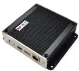
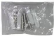
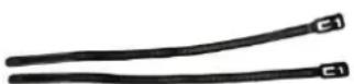
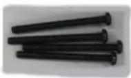
| Package Contents | ECD-1000 unit, screw packs, cable straps, mounting bracket, power adaptor, terminal block, quick installation guide, warranty card |
Frequently Asked Questions - ECD-1000 ACTi
User questions about ECD-1000 ACTi
0 question about this device. Answer the ones you know or ask your own.
Ask a new question about this device
Download the instructions for your Digital decoder in PDF format for free! Find your manual ECD-1000 - ACTi and take your electronic device back in hand. On this page are published all the documents necessary for the use of your device. ECD-1000 by ACTi.
USER MANUAL ECD-1000 ACTi
natural_image
Abstract geometric design with a red square and a gray star-like shape (no text or symbols)ECD-1000
User Manual
For V1.02.09 Firmware
Ver. 2014/10/03
Legal Notice
Disclaimer
- The information contained in this document is intended for general information purposes. ACTi Corporation shall not be liable for errors contained herein or for incidental or consequential damages arising from the furnishing, performance, or use of this manual.
- The information contained herein is subject to change without notice.
- The English version of this document is the official one for all purpose. All the translated versions are provided as a convenience. Any discrepancies or differences created in the translations of any other languages are not legally binding.
Copyright
Copyright © 2014 ACTi Corporation. All Rights Reserved.
Trademarks
- ACTi Connecting Vision and its logo Corporation.
- Microsoft ^ and Windows ^ are registered trademarks of Microsoft Corporation.
- All other product or company names mentioned in this document may be trademarks or registered trademarks of their respective owners.

Regulatory Compliance Information
Federal Communications Commission Statement

This equipment has been tested and found to comply with the limits for a Class B digital device, pursuant to Part 15 of the FCC Rules. These limits are designed to provide reasonable protection against harmful interference in a residential installation. This equipment generates, uses
and can radiate radio frequency energy and, if not installed and used in accordance with the instructions, may cause harmful interference to radio communications. However, there is no guarantee that interference will not occur in a particular installation. If this equipment does cause harmful interference to radio or television reception, which can be determined by turning the equipment off and on, the user is encouraged to try to correct the interference by one or more of the following measures:
- Reorient or relocate the receiving antenna.
- Increase the separation between the equipment and receiver.
- Connect the equipment into an outlet on a circuit different from that to which the receiver is connected.
- Consult the dealer or an experienced radio/TV technician for help.
WARNING: Changes or modifications to the equipment that are not expressly approved by the responsible party for compliance could void the user's authority to operate the equipment.
European Community Compliance Statement

This product has been tested and found to comply with the limits for Class B Information Technology Equipment according to European Standard EN 55022 and EN 55024. In a domestic environment, this product may cause radio interference in which cause the user be require
to take adequate measures.
About This Manual
Target Audience
This manual is intended for System Administrators who are responsible for installing and setting up video surveillance system as well as End Users who will be operating ECD on a daily basis. System Administrators are expected to know the fundamentals of IP surveillance system integration and to own the administrative privileges to install and configure all the devices.
For the latest product updates and documentation, visit our website:
http://www.acti.com/downloadcenter
Technical Support
If you have any questions during system installation, please feel free to contact our engineers via our Customer Help Desk platform http://www.acti.com/CHD.
Table of Contents
Chapter 1: Hardware Overview ...... 10
1.1 Introduction ...... 11
Package Contents....11
Device Overview....12
System Requirements....13
Supported Video Format....13
Decoding Limitation....13
1.2 Connecting Devices 15
Connection Architecture 15
Preparing the Power Adaptor....16
Connecting to Local Display....17
Local Display via HDMI Connection 17
Local Display via Composite Connection 17
Connecting the Cameras....18
1.3 Accessing ECD-1000.... 19
Local Access 19
Remote Access 19
Local vs. Remote Access 19
1.4 Device Maintenance.... 20
Resetting the Device 20
Switching Between NTSC and PAL Mode....20
Chapter 2: Local Management ...... 21
2.1 Accessing for the First Time 22
Quick Setup....23
Step 1: Login ......23
Step 2: Change the IP Address (If necessary)....23
Step 3: Add Cameras ....24
2.2 The Live View Screen.... 27
The Menu Panel 28
Changing the Layout....29
Viewing Channels in Full Screen 30
Viewing Channels by Patrol 31
Repositioning Channels....31
2.3 The Login Screen 33
Using the On-Screen Keyboard 34
2.4 Using the PTZ Control Panel 35
Setting Preset Points 37
Setting Tours 39
2.5 Accessing the Setup Screen 42
The Setup Screen....42
2.6 Configuring System Settings.... 43
System Information....43
Module 44
Date and Time....44
Automatically Set the Date and Time....44
Manually Change the Date and Time 45
Sync Date and Time with NTP Server 46
Language 46
Mouse....47
Local Display....47
Local Audio Out 48
2.7 Configuring Network Settings...... 49
Viewing the Network Information....49
Configuring the Network Connection ....50
Setting the IP Address Manually....50
Obtaining the IP Address Automatically ....51
Configuring Port Mapping....51
2.8 Configuring the Cameras....52
The Camera Setup Page 52
Adding Cameras....53
Searching Cameras to Add 53
Adding Cameras Manually ....55
Adding ONVIF-Compliant Cameras Manually ....57
Adding Cameras Manually via RTSP....58
Modifying Camera Settings....61
Reconnecting Cameras....64
Deleting Cameras....64
2.9 Managing Network Loss Event 65
Scheduling Network / Video Loss Trigger....65
Enabling Beep Sound Trigger....67
Copying Event Schedule Settings....68
2.10 Rebooting the Device....69
Chapter 3: Remote Management....70
3.1 Accessing ECD-1000 Remotely 71
How to Access ECD-1000? 71
Accessing From a Network with DHCP Server....71
Accessing From a Network without DHCP Server....73
The Login Screen....74
The Setup Wizard....75
3.2 The Live View Page 78
Viewing the Cameras 80
Changing the Window Layout....82
Patrolling Channels 83
Syncing Remote and Local Live View Display....84
Reconnecting the Cameras....84
Removing Video Stream from Live View....84
Using Optical / Digital PTZ 85
Taking Snapshots....86
Using the PTZ Control Panel 87
Viewing by Preset Point and Tour....88
Using the Toolbar....89
3.3 The Setup Screen....91
3.4 Configuring the System Settings 92
System Information....92
Date and Time....93
Automatically Set the Date and Time....93
Manually Change the Date and Time 93
Sync Date and Time with NTP Server 94
Module....95
Language 95
Local Display....96
3.5 Configuring the Network Settings 97
Viewing the Network Information....97
Configuring the Network Connection 98
Setting the IP Address Manually....98
Obtaining the IP Address Automatically 99
Configuring Port Mapping....99
3.6 Configuring the Cameras.... 100
Adding Cameras....101
Searching Cameras to Add 101
Adding Cameras Manually ....103
Modifying Camera Settings....107
Deleting Cameras....110
Setting Preset Points on the Remote Client 111
Setting Preset Tours on the Remote Client 112
3.7 Configuring User Access.... 114
Creating Groups....114
Adding Users....116
Granting Access Permission.... 117
Managing Groups and Users.... 118
3.8 Managing Network Loss 119
Scheduling Network Loss Trigger.... 119
Enabling Beep Sound Trigger....121
Deleting Beep Trigger 121
Copying Event Schedule Settings....122
3.9 System Maintenance 123
Upgrading the Firmware....123
Saving Backup Settings 124
Restoring Backed Up Settings 125
Troubleshooting....126
3.10 Managing the System Log 127
3.11 Rebooting the Device.... 127
Chapter 4: Installation and Maintenance ...... 128
4.1 How to Surface Mount?...... 128
4.2 How to Use VESA Mount?...... 129
4.3 How to Use the Pole Mount?...... 130
Chapter 1: Hardware Overview
This chapter contains the following topics:
- Introduction: Describes the package contents, device overview, and the connection architecture.
- Connecting Devices: Describes how to connect ECD-1000 to other devices and how to use the bundled accessories.
- Accessing the Device: Describes the different methods on how to access the device via local display or remote management.
1.1 Introduction
Package Contents
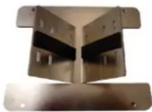
| ECD-1000 | Screw Packs x 2 | Cable Straps |
 |  |  |
 | ||
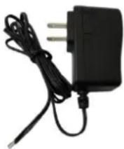
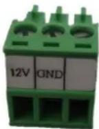
| Mounting Bracket | Power Adaptor | Terminal Block |
 |  |  |
| Quick Installation Guide | Warranty Card | |
 |  | |
Device Overview
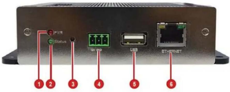
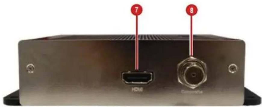
| Item | Description | |
| 1 | Power LED | Lights RED when the power is on. |
| 2 | System Ready LED / Factory Default LED | Lights GREEN after the boot up process is complete to indicate ECD-1000 is ready.When doing a factory reset, this LED lights GREEN briefly to indicate factory default setting restoration has started. The LED turns off and lights up again when the restoration completes and ECD-1000 is ready for use. |
| 3 | Reset Button / NTSC and PAL Switch | Use to restore ECD-1000 to its factory default setting.Use to switch between NTSC and PAL functions. |
| 4 | DC 12V Power Connector | Connects the bundled power adaptor and terminal block to ECD-1000. See Preparing the Power Adaptor on page 16. |
| 5 | USB Port | Connects a USB device, such as a mouse, keyboard or hub, to ECD-1000. |
| 6 | Ethernet Port | Connects to the network using an Ethernet cable. |
| 7 | HDMI Port | Connects to an HDMI monitor (1080p) using an HDMI cable. |
| 8 | Composite Port | Connects to a composite monitor using a video cable with BNC connector. |
System Requirements
For remote computer access, the following system requirements must be met to ensure compatibility with ECD-1000:
| PC Spec | Minimum Requirement |
| CPU Processor | Intel Core 2 Quad 2.66 GHz or newer |
| RAM | At least 4GB |
| Operating System | Windows 7 (32/64-bit), Windows 8 (All versions) |
| Browser | Internet Explorer 9.0 or 10.0 |
Supported Video Format
| LocalLive View | RemoteLive View | |
| Codec | H.264 | MPEG4MJPEGH.264 |
| Resolution | Up to 2 megapixels | Up to 10 megapixels |
ECD-1000 conforms to the display standard of composite and 1080p HDMI monitors.
Therefore, to reserve as much computing power for ECD-1000 as possible, only up to 2
megapixels H.264 video stream can be displayed on the Local Live View. A black screen with a message will appear for channels using other codecs or those with higher resolution.
Decoding Limitation
Depending on the video stream resolution, ECD-1000 automatically adjusts the frame rate of the stream in order to achieve smooth video performance as well as support the most number of channels as possible. For example, when viewing 9 channels with 1920 x 1080 resolution in a 9-channel mode, ECD-1000 automatically switches the frame rate to 12 fps on each camera
to display all the 9 channels. Other frames are automatically dropped in the process.
| Video Stream Resolution | 4-Channel Mode | 9-Channel Mode | 12-Channel Mode | 16-Channel Mode |
| VGA(640 x 480) | 4 channels@ 30 fps | 9 channels@ 30 fps | 12 channels@ 30 fps | 16 channels@ 30 fps |
| 720p(1280 x 720) | 4 channels@ 30 fps | 7 channels@ 30 fps | 7 channels@ 30 fps | 7 channels@ 30 fps |
| 9 channels@ 25 fps | 12 channels@ 16 fps | 16 channels@ 12 fps | ||
| 1.3M(1280 x 1024) | 4 channels@ 30 fps | 6 channels@ 30 fps | 6 channels@ 30 fps | 1~16 channelsDecode I Frame only |
| 9 channels@ 20 fps | 12 channels@ 15 fps | |||
| 1080p(1920 x 1080) | 4 channels@ 30 fps | 4 channels@ 30 fps | 4 channels@ 30 fps | 1~16 channelsDecode I Frame only |
| 9 channels@ 12 fps | 9 channels@ 10 fps |
NOTE: Regardless of the configured frame rate of a camera video stream, ECD-1000 automatically adjusts the frame rate according to the table above.
1.2 Connecting Devices
Connection Architecture
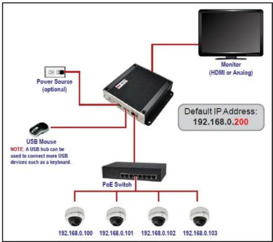
The diagram below illustrates a sample connection within a local area network.
flowchart
graph TD
    A["Power Source (optional)"] --> B["Switch"]
    C["USB Mouse"] --> B
    D["Monitor (HDMI or Analog)"] --> B
    B --> E["PoE Switch"]
    E --> F["192.168.0.100"]
    E --> G["192.168.0.101"]
    E --> H["192.168.0.102"]
    E --> I["192.168.0.103"]
    J["Default IP Address: 192.168.0.200"] --> B
Local Area Network Connection Architecture
- Connect the power adaptor to ECD-1000 and power outlet (see Preparing the Power Adaptor on page 16).
NOTE: This step may be skipped if a Power-over-Ethernet (PoE) switch or injector will be connected to ECD-1000.
-
Connect a monitor to ECD-1000 via HDMI or Composite port connection (see Connecting to Local Display on page 17).
-
Connect a USB mouse.
-
Connect ECD-1000 to a Power-over-Ethernet (PoE) switch or injector.
NOTE: If using the bundled power adaptor, a non-PoE switch may also be used.
- Connect the cameras to the switch (see Connecting the Cameras on page 18).
Preparing the Power Adaptor
In case of using a non-PoE Ethernet switch, use the bundled power adaptor to directly connect ECD-1000 to a power outlet. The power adaptor must be connected to the supplied terminal block before use.
To do this, follow the procedures below:
- Loosen the screws of the 12V and GND pins of the power terminal block.
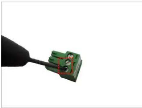
natural_image
Close-up of a green electrical connector being inserted with a black tool (no text or symbols visible)- Take note that the power adaptor cable has two (2) different wires:
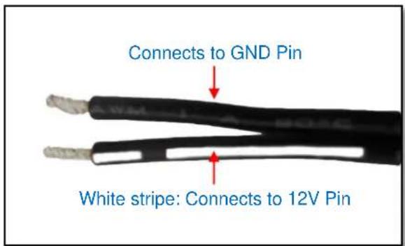
- Connect the wire with the white stripe to the 12V pin and the other to the GND pin.
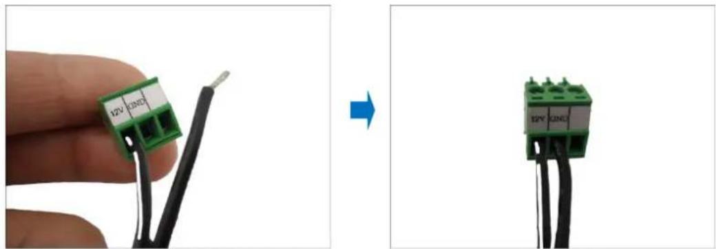
natural_image
Two-step diagram showing a hand holding a green 12V I2NC3 connector connected to black wires, with no visible text or symbols.- Tighten the screws of the 12V pin and the GND pins to secure the wire connection.
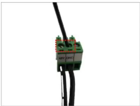
natural_image
Close-up of a green electrical connector with red indicator lights, connected to black wires (no text or symbols visible)Connecting to Local Display
ECD-1000 supports up to two display outputs via HDMI and Composite connection at one time. These display outputs can be referred to as the local display or the local client.
Local Display via HDMI Connection
Connect an HDMI monitor (1080p) to the HDMI port of ECD-1000 using an HDMI cable (not included in the package).
Local Display via Composite Connection
Connect a composite monitor to the Composite port of ECD-1000 using a video cable with BNC connector (not included in the package).
Connecting the Cameras
ECD-1000 can decode up to 16 IP cameras or video encoders and display the videos through an HDMI (1080p) or composite monitor or display remotely via PC or a mobile client.
To connect a camera, do the following:
- Connect the camera to a PoE switch, within in the same network segment as ECD-1000, using an Ethernet cable.
- Configure the IP address of the camera, if necessary (please refer to the camera hardware manual on how to do this).
- Once ready, access ECD-1000 user interface to search and finalize the camera connection (see Quick Setup on page 23).
1.3 Accessing ECD-1000
ECD-1000 can be accessed and managed in two ways: via Local access or Remote access.
Local Access
A monitor that is directly connected to ECD-1000 via the HDMI or Composite port is considered Local Access by a Local Client. Users can view the videos from the camera and manage network configurations right through the monitor.
To access ECD-1000 user interface, simply connect a USB mouse and a monitor to ECD-1000.
See Chapter 2: Local Management on page 21 for more information.
Remote Access
Remote Access is connected over the TCP/IP network and communicates through HTTP protocol. Remote access can either be from a web or mobile client. A computer with a web browser is a web client and a mobile device with the Active Mobile Client software is a mobile client. Both are considered Remote Clients.
On a computer with Internet Explorer, users can access ECD-1000 web interface by typing the IP address of ECD-1000 without installing any client program beforehand. Logging in is as simple as visiting a website.
Users can also view the videos via Active Mobile Client using mobile devices, like iPhone, iPad, iPod and Android devices. This feature only allows the users to view videos, advanced configurations must still be done through the local client or remote access through a web client. For more information, please refer to the Mobile Client documentation downloadable from the website (www.acti.com).
NOTE: For simplicity, the term "Remote access" all throughout this documentation refers to remote access by a web client (PC).
Local vs. Remote Access
In most cases, it is recommended to perform the initial configurations, before ECD-1000 is even mounted to its location, using local access. Once the initial configurations are complete, install ECD-1000 and start viewing the videos through the local display. Further management or advanced security settings may be done through remote access.
1.4 Device Maintenance
This section describes how to reset the device and switch between NTSC and PAL system.
Resetting the Device
In case there is a need to reset the device to its default factory settings, perform the following:
- With the device powered off, press and hold the Reset button with a pointed object (e.g. pen).
- Power on ECD-1000, either by connecting the power adaptor or connecting ECD-1000 to a PoE switch.
- Continue to press the Reset button for 5 seconds or when the Factory Default LED lights green. The Factory Default LED indicates resetting has started. The Factory Default LED lights on and off several times until it completely lights up to indicate reset is complete.
Switching Between NTSC and PAL Mode
When ECD-1000 is powered on, briefly press the NTSC and PAL switch (also the Reset button) to switch between NTSC and PAL mode.
Chapter 2: Local Management
This chapter describes ECD-1000 operation and management on the Local Client side. It contains the following topics:
- Accessing for the First Time: Describes the setup procedures involve when accessing ECD-1000 for the first time. This includes changing ECD-1000 IP address and adding the cameras.
- The Live View Screen: Describes how to use the Live View screen, changing the layout, channel patrolling and resetting the channel position.
- Accessing the Setup Screen: Describes how to access the Setup menu, using the on-screen keyboard to login, and an overview of the Setup menu.
- Configuring System Settings: Describes how to view and modify the system settings such as date and time, language, and how to filter information shown on the local display.
- Configuring Network Settings: Describes how to modify the IP configurations, port mapping and other network settings.
- Configuring the Cameras: Describes how to add and view the cameras and manage the camera settings.
- Rebooting the Device: Describes how to do a system reboot.
2.1 Accessing for the First Time
Once all devices are connected, turn on the monitor to see the Live View screen.
| 01 Camera | 02 Camera | 03 Camera |
| 04 Camera | 05 Camera | 06 Camera |
| 07 Camera | 08 Camera 2013/07/22 18:30:27 □ 192.168.0.200 | 09 Camera |
Network Connection Status:
Network Disconnected
Cable is unplugged
Connected
ECD-1000 comes with a default static IP address of 192.168.0.200. If your network has a DHCP server, ECD-1000 will automatically switch the connection type to DHCP and be assigned an IP address.
Use the USB mouse to navigate through the user interface. Move the mouse cursor towards the bottom of the screen to display the Menu Panel
| 01 Camera | 02 Camera | 03 Camera |
| 04 Camera | 05 Camera | 06 Camera |
| 07 Camera | 08 Camera | 09 Camera |
| 2014/02/18 10:34:12 | ||
Menu Panel
Quick Setup
Step 1: Login
- Click to access the Setup screen.
- When prompted to login, enter the default Account and Password using the on-screen keyboard.
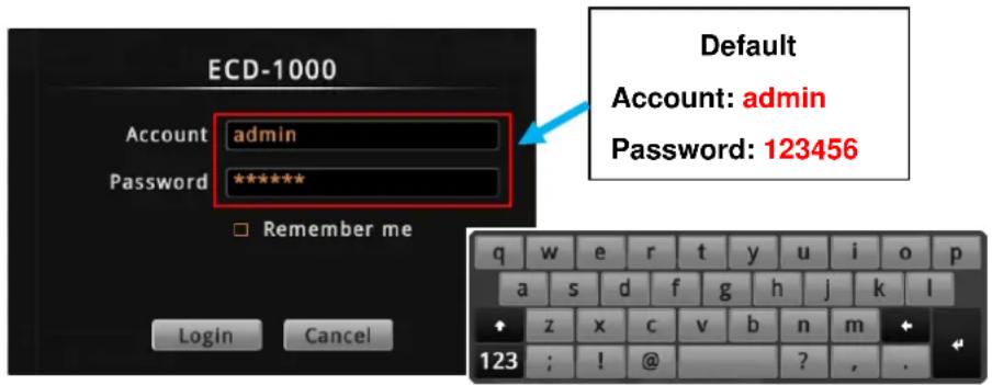
NOTE: For more information on using the on-screen keyboard, see Using the On-Screen Keyboard on page 34.
Step 2: Change the IP Address (If necessary)
If the network has a DHCP server, ECD-1000 is automatically assigned an IP address so users do not need to change anything. If the network does not have a DHCP server, ECD-1000 uses its default IP address of 192.168.0.200.
Change the IP Address on Network without DHCP Server
Remember that ECD-1000 must be on the same network segment as the cameras. In case you need to change the IP address of ECD-1000, follow the procedures below on how to do this.
- Click Network > Network Connection.
- Make sure Connection Type is Manual.
- Change the IP address using the on-screen keyboard (see Using the On-Screen Keyboard on page 34 for information on using the on-screen keyboard).
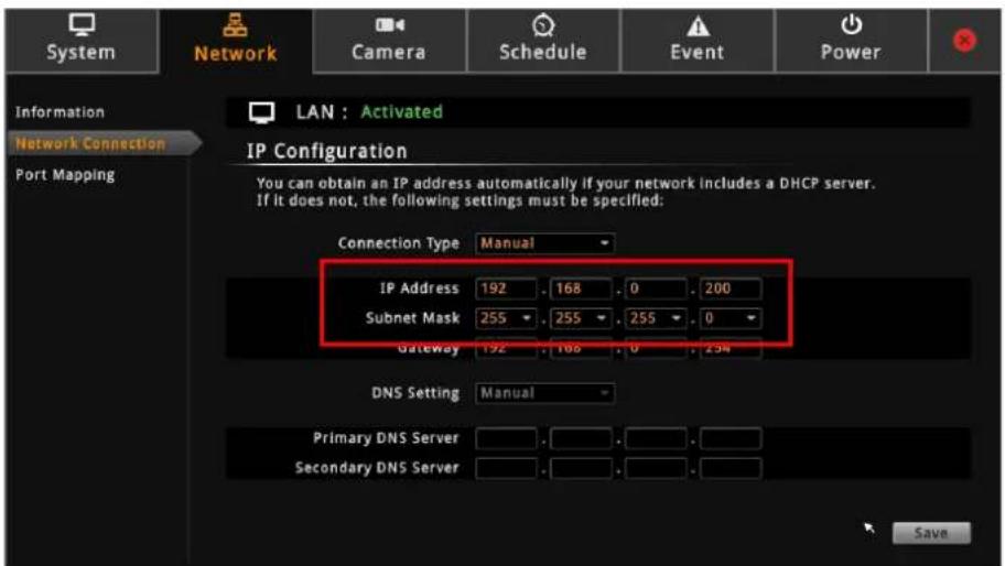
- Click Save.
- When LAN shows "Activated", the IP address configuration is complete.
Step 3: Add Cameras
- On the Setup screen, click Camera > Search Cameras.
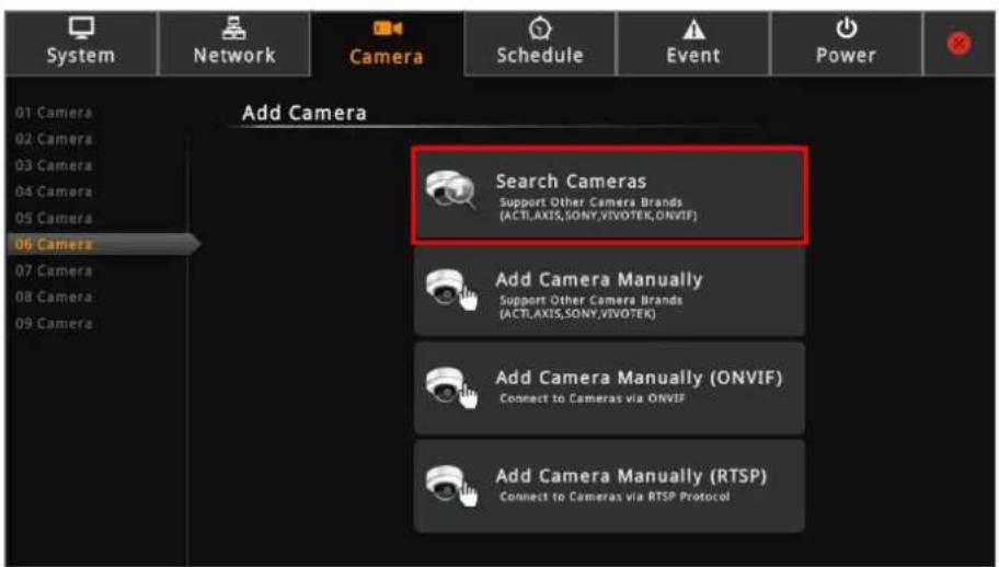
NOTE: To add cameras by IP address or connect to camera via RTSP protocol, see Adding Cameras on page 53.
- The Search Cameras screen appears with the list of cameras on the same network. By default, the camera manufacturer, user account name and password for access are already filed with ACTi default values. Modify these values as needed.
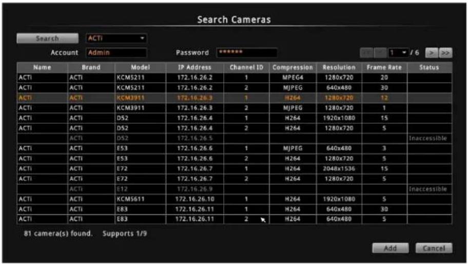
NOTE: ECD-1000 supports third-party cameras. To validate specific camera models that can be integrated, visit our website (http://www.acti.com/3rdpartycamera).
- Click one or more camera model(s). Selected cameras are displayed in orange.
NOTE: By default, a maximum of nine cameras can be added. You can add more than nine cameras later by configuring Module to 12-channel or 16-channel mode, see Module on page 44.
- Click Add. The Camera screen appears with the list of the selected cameras on the left panel. In the illustration below, only seven cameras are added.
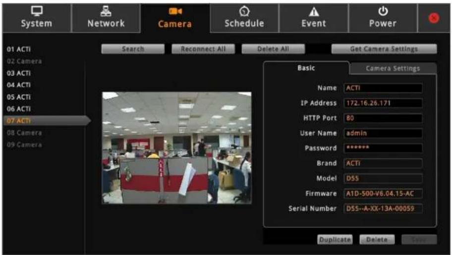
- Click ✗ to close the Setup screen. The Live View screen appears with the added cameras.
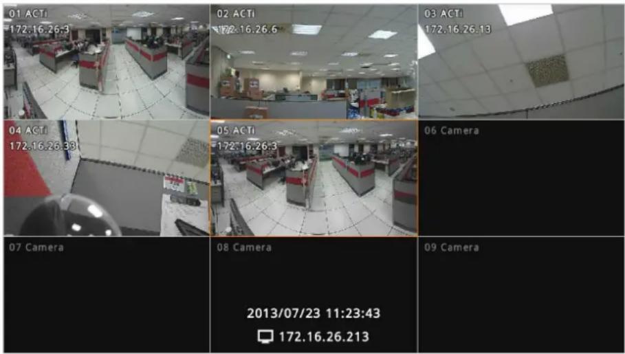
By default, information such as the camera name, IP address, etc. are displayed on the local display. For security purposes, these information may be hidden, see Local Display on page 47 for more information.
2.2 The Live View Screen
Different types of information are displayed on the Live View screen.
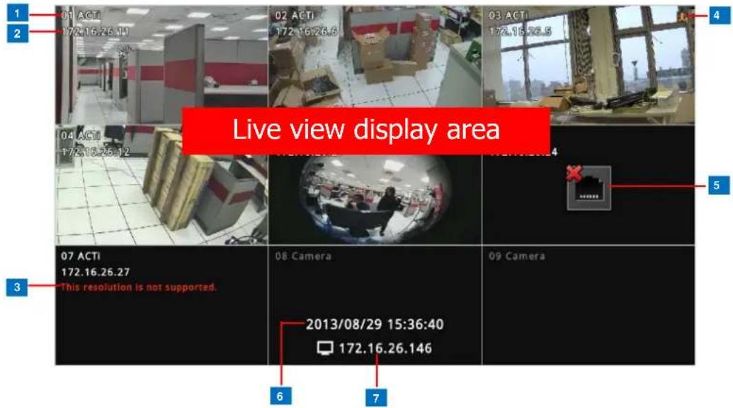
| Item | Description | |
| 1 | Channel Number and Name | Displays the channel number and camera name. |
| 2 | Channel IP Address | Displays the IP address of the camera. |
| 3 | Warning Message | Displays the warning message:This resolution is not supported: Local display supports camera resolution of up to 1920 x 1080 only. If the resolution exceeds this value, this message is displayed.The compression is not supported: Local display supports H.264 compression only. |
| 4 | Event Trigger Icon | Indicates an event has happened, such as motion is detected or a digital input is triggered. These triggers are based on the events configured on the camera side. |
| 5 | Connection Error | Indicates the camera is disconnected from the network. |
| 6 | System Date and Time | The system date and time. |
| 7 | ECD-1000 IP Address | The IP address of ECD-1000. |
The Menu Panel
Move the mouse cursor towards the bottom of the screen to display the Menu Panel.
From the Menu Panel, users can modify the channel layout, start viewing channels on patrol, stretch image, reposition the channels, and access the Setup screen.

| Item | Description | |
| 1 | Layout Icons | Click an icon to change the layout of channels. The current layout is indicated by an orange icon. Moving the mouse over the icon displays the icon name. See Changing the Layout on page 29. |
| 2 | Sequence Patrol | Sequence Patrol allows users to view the one or more channels at a time and patrols with a specific interval time. See Viewing Channels by Patrol on page 31. |
| 3 | Stretch / Un-stretch Video | Click to stretch or un-stretch the video. |
| 4 | Reset Channel Position | Click to reposition the channels according to channel sequence. See Repositioning Channels on page 31. |
| 5 | PTZ Control | Click to display the PTZ control panel. See 2.4 Using the PTZ Control Panel on page 35. |
| Setup | Click to access the Setup screen. See 2.5 Accessing the Setup Screen on page 42. | |
Changing the Layout
By default, the local Live View is displayed with a 9-channel layout. The layout can be changed into a 1-channel, 2-channel, 1+7-channel display, etc. Available layout varies depending on current channel mode (see Module on page 44).
| Layout 1 | Layout 2 | Layout 4 |
Click to display one channel on full screen. | Click to display 2 channels at a time.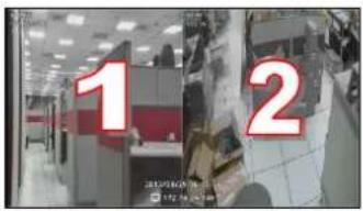 | Click to display 4 channels at a time.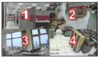 |
| Layout 9 | Layout 12 | Layout 16 |
Click to display 9 channels at a time.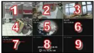 | Click to display 12 channels at a time.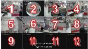 | Click to display 16 channels at a time.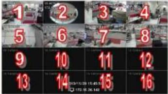 |
| Layout 1+5 | Layout 1+7 | Layout 1+12 |
Click to display 6 channels at a time on a 1+5 layout.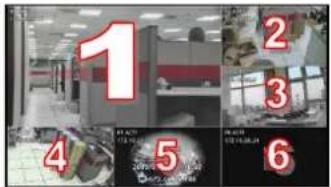 | Click to display 8 channels at a time on a 1+7 layout.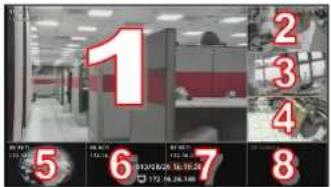 | Click to display 13 channels at a time on a 1+12 layout.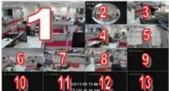 |
| Layout 2+4 | Layout 2+8 | |
Click display 8 channels at a time on a 2+4 layout. 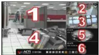 | Click display 10 channels at a time on a 2+8 layout. 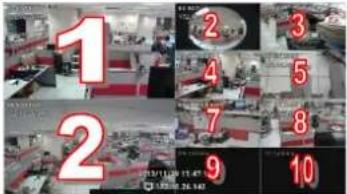 | |
To view succeeding channels, click the layout icon again. For example, if viewing on a
2-channel layout, and you want to view the next 2 channels, click

Viewing Channels in Full Screen
Double-click a channel to view the channel in full screen.
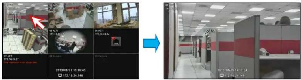
Double-click again to switch back to the previous layout.
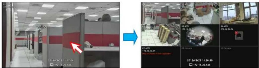
Viewing Channels by Patrol
Instead of viewing all channels at the same time, users may want to view one channel in full screen and scroll through all the channels at a time. To do this, follow the procedures below:
-
Click to start Sequence Patrol.
-
Enter the interval time (in seconds) using the on-screen keyboard (see Using the On-Screen Keyboard on page 34). Then click OK.
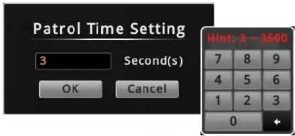
- Sequence Patrol starts. To stop the patrol, click .
Repositioning Channels
By default the channels are displayed according to the sequence of the channel numbers. To reposition the channel, use the mouse to drag the channel from its location to another location. See examples below.
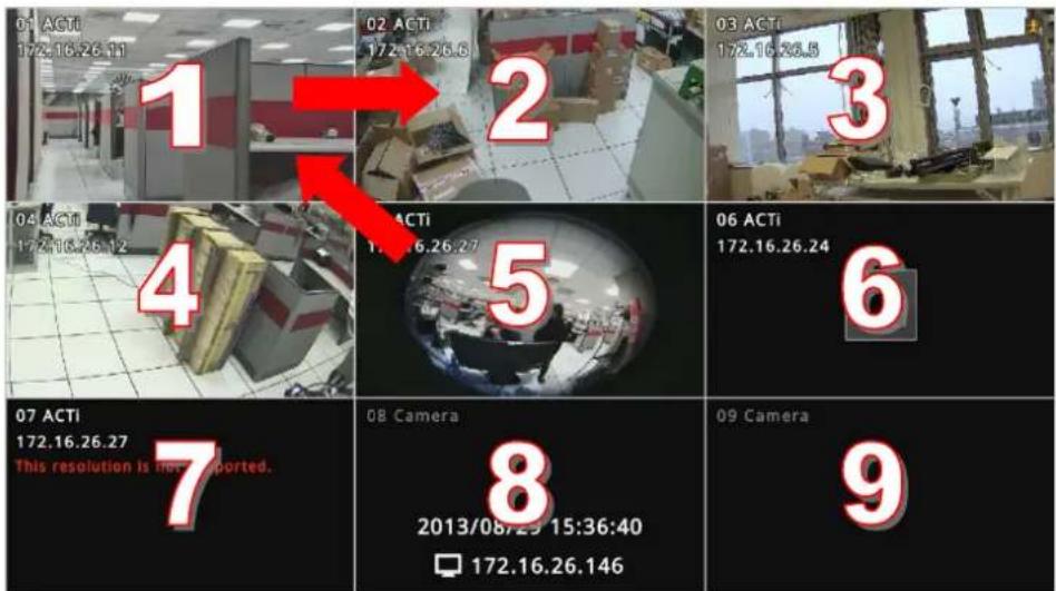
Default Channel Position
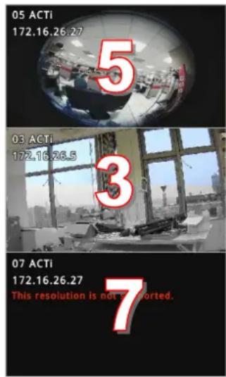
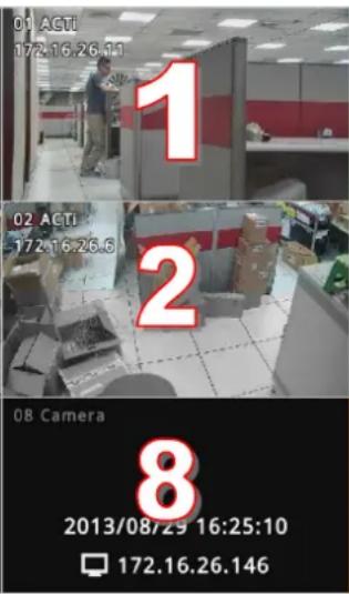
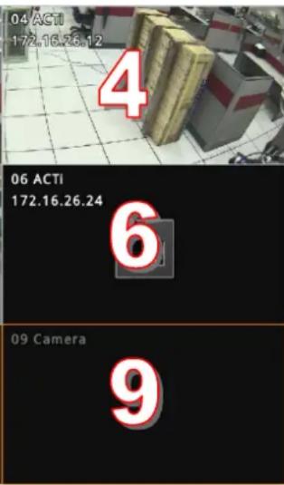
Repositioned Channels
To reset the default channel position, click

2.3 The Login Screen
The Login screen appears before users can access the PTZ Control Panel and the Setup Page.
When prompted to login, enter the default Account and Password using the on-screen keyboard.
For security purposes, it is recommended to modify the account name and password through a remote client computer.
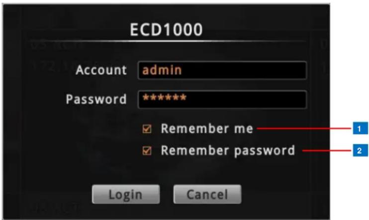
| Item | Description | |
| 1 | Remember Me | Check to allow the system to remember the account name.Users just need to enter the password to login. |
| 2 | RememberPassword | Check to allow the system to remember the account password so users do not need to type the password anymore. This option is shown only if Remember me is checked.NOTE:This can be a security risk for any other use may be able to access the Setup screen. |
Using the On-Screen Keyboard
The on-screen keyboard allows users to enter text without using a physical computer keyboard. The on-screen keyboard appears when users click on fields that require character or numeric input, such as account name, password, etc. Using the mouse, click the keys on the on-screen keyboard to enter characters or numbers.
The type of on-screen keyboard that appears may vary depending on the required text for input.
![Standard Alphabet +Symbol Keyboard q w e r t y u i o p a s d f g h j k l ↑ z x c v b n m + 123 ; ! @ ~ ? , . Number + Symbol Keyboard 1 2 3 4 5 6 7 8 9 0 / \ ` ~ - _ : < > #+= ( ) [ ] { } | + abc ; ! @ ~ ? , . Symbol Keyboard " ' # $ % ^ & * + = / \ ` ~ - _ : < > 123 ( ) [ ] { } | + abc ; ! @ ~ ? , .](/content/2026/05/859731/images/7e6675dd73472b4957d22f74584dd7c0a2d3430497ff53422d3133632fd8dc8a.jpg)
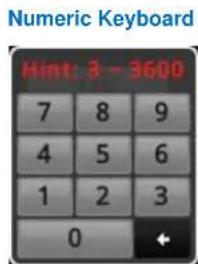
NOTE: The on-screen keyboard may also contain tips or hints for input.
2.4 Using the PTZ Control Panel
You can pan, tilt and zoom PTZ cameras locally using the PTZ Control Panel, as well as create preset points and start tour.
To display the PTZ Control Panel, move the mouse over the bottom of the screen to display
the Menu Panel, then click 📋u must login as an administrator to have PTZ control access (see 2.3 The Login Screen on page 33 for details).
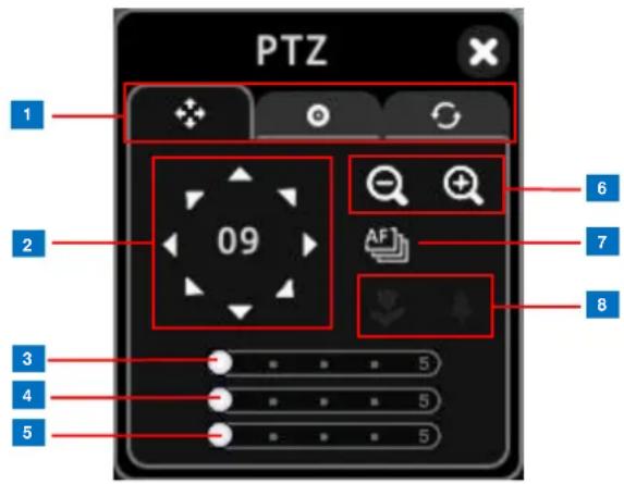
TIP: Move the mouse over the icon to display the function name.
NOTE:
- The PTZ control panel is enabled only when a PTZ or zoom camera is selected. Although the panel appears when a non-PTZ/zoom camera is selected, all the controls are disabled.
- Digital PTZ is available on all cameras when using a remote client. See How to Use Digital PTZ on page 86.
| Item | Description | |
| 1 | PTZ ControlTab | Click the tab to display the page:PTZ [X806]Preset Points  Setting Preset Points on page 37)Tour [CBWA] Setting Tours on page 39) Setting Preset Points on page 37)Tour [CBWA] Setting Tours on page 39) |
| 2 | Pan / TiltControls | Click the arrows to pan / tilt the camera according to the configured speed on the sliders. The enclosed number indicates the currently selected channel. |
| 3 | Pan Speed | Drag the slider to adjust the pan speed; 1 (slowest) to 5 (fastest). |
| 4 | Tilt Speed | Drag the slider to adjust the tilt speed; 1 (slowest) to 5 (fastest). |
| 5 | Zoom Speed | Drag the slider to adjust the zoom speed; 1 (slowest) to 5 (fastest). |
| 6 | Zoom Control | Click the icons to zoom in or zoom out the camera view. |
| 7 | Focus Mode | Click the icon to toggle between modes:Auto FocusManual Focus: When Manual Focus is selected, the Near Focus and Far Focus icons become enabled.Click one of the focus icons to adjust the focus manually; you may also need to adjust zoom (6) to achieve the best focus and viewing angle. |
Setting Preset Points
A preset point is a user-defined area where the camera zooms in. Up to 32 preset points can be configured on ECD-1000. When preset points are created on ECD-1000, they are automatically synced on the camera side, and vice versa.
On the Live View screen, move the mouse over the bottom of the screen to display the Menu
Panel, then click 📁u must login as an administrator to have PTZ control access
(see 2.3 The Login Screen on page 33 for details). Then click the Preset Point Tab

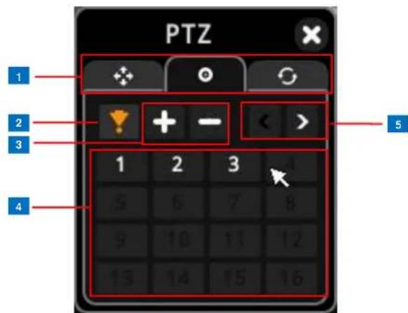
| Item | Description | |
| 1 | PTZ ControlTab | Click the tab to display the page:PTZ (see 2.4 Using the PTZ Control Panel on page 33).Preset PointsTour (see Setting Tours on page 39) |
| 2 | Go to Preset | Click to enable “go to” preset mode, then click a preset point number below to make the camera zoom into the defined preset point. The orange icon indicates the function is currently selected. |
| 3 | Add / Remove Preset | Click + to add a new preset point. See below.Click – to remove a preset point. |
| 4 | Preset Point | The numbers indicate the preset point ID. Once a preset point is configured, the number turns white. Up to 32 preset points can be configured. |
| 5 | Back / Next Page | Click < to go back the previous page and > to go to the next page. |
How to Create / Modify Preset Points
- On the Live View screen, move the mouse over the bottom of the screen to display the
Menu Panel, then click 📁u must login as an administrator to have PTZ control access (see 2.3 The Login Screen on page 33 for details).
- Pan, tilt and zoom the camera to the desired preset point.
- Click the Preset Point Tab .
- Click +, the icon turns orange. Then click a preset point number to assign.
NOTE: Numbers in red are already configured; when red numbers are selected, the original preset setting will be overridden with the current preset point.
- Type a preset point name using the on-screen keyboard (see Using the On-Screen Keyboard on page 34).
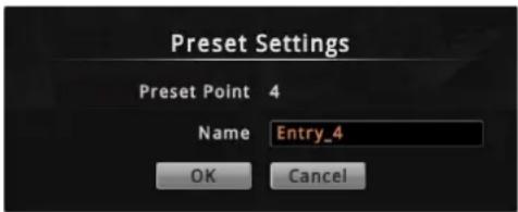
- Click OK to complete.
How to Delete Preset Points
- On the Preset Point page tab, click ☐, the icon turns orange.
- Click the preset point number to remove. The number icon turns gray to indicate that the preset point is already deleted.
Setting Tours
Several preset points can be grouped into a "Tour" which directs the camera to cycle through the series of preset points at specific interval time. Up to 32 tours can be set on ECD-1000. The tour configuration is saved only on ECD-1000, not on the camera side.
On the Live View screen, move the mouse over the bottom of the screen to display the Menu
Panel, then click 📋. You must login as an administrator to have PTZ control access (see 2.3
The Login Screen on page 33 for details). Then click the Preset Point Tab

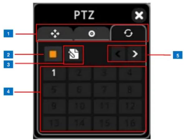
| Item | Description | |
| 1 | PTZ ControlTab | Click the tab to display the page:PTZ (see page 33).Preset Points (see page 37).Tour |
| 2 | Stop Tour | When the camera is on tour, click this icon to stop the tour. |
| 3 | Create / EditTour | Click this icon to create or modify a tour. SeeHow to Create /Modify Tourson page 40. |
| 4 | Tour IDNumber | The numbers indicate the tour ID. If the number is:Red: The tour is currently running.White: The tour is set but not running.Gray: The tour is not set.Click a tour ID number to start the tour. |
| 5 | Back / NextPage | Click < to go back the previous page and > to go to the next page. |
How to Create / Modify Tours
To create tours, make sure one or more preset points have already been created. The tour configuration on ECD-1000 is not synced with the tour configuration on the camera side.
- On the Live View screen, move the mouse over the bottom of the screen to display the
Menu Panel, then click 📄u must login as an administrator to have PTZ control access (see 2.3 The Login Screen on page 33 for details).
-
Click the Tour tab
-
Click .
-
Select the tour ID and type the desired tour Name (see Using the On-Screen Keyboard on page 34).
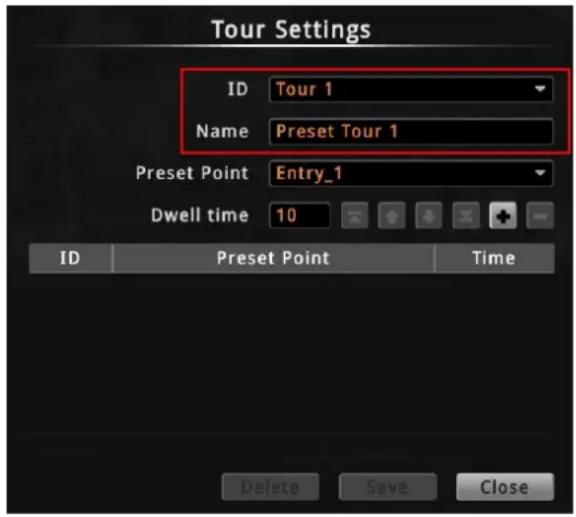
- On Preset Point, select the preset point that you want to include in the tour and set the Dwell time. Dwell time is the amount of time (in seconds) where the camera stays in that preset point. Then, click the selected preset point is added to the table below.
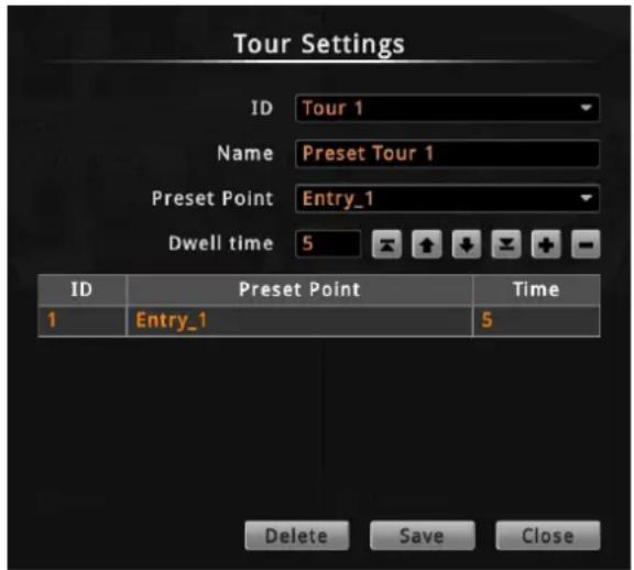
- Repeat steps 4 to 5 to add more preset points to the tour.
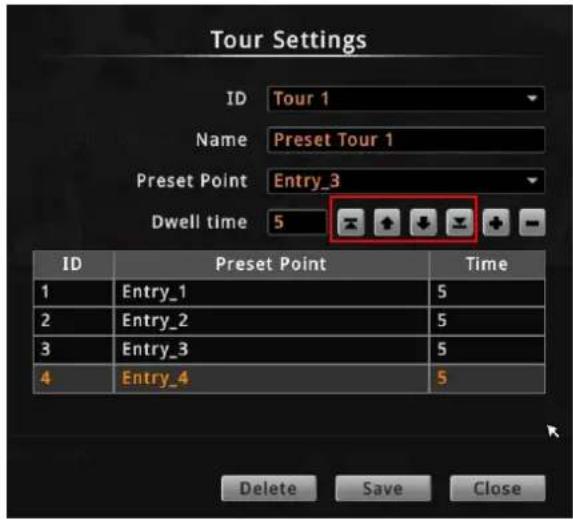
TIP: Use the arrow keys to change the order sequence of preset points. Or, to remove a preset point from the tour, click
- When done, click Save to complete the tour configuration.
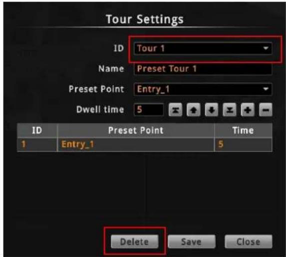
How to Delete Tours
- On the Tour page tab, click .
- On ID, select the tour you want to remove.
- Click Delete.
- Click Close to close Tour Settings.
2.5 Accessing the Setup Screen
The Setup screen allows users to configure the system and network settings and add or delete cameras for viewing. Users must login with an administrator account first to access the Setup screen.
To access the Setup screen, click 🎨 on the menu panel. The Login screen appears (see
2.3 The Login Screen on page 33).
The Setup Screen
After a successful login, the Setup screen appears.
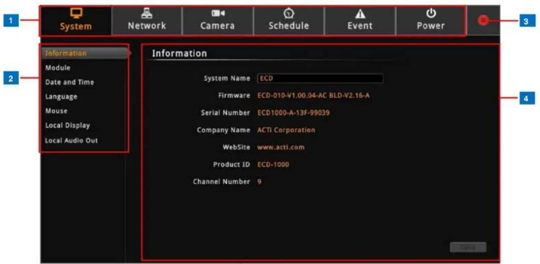
| Item | Description | |
| 1 | Setup Menu | Click a tab to display the submenu. |
| 2 | Submenu Panel | Displays the submenu options. Click a submenu to view the settings page. |
| 3 | Exit | Click to close the Setup screen. Once closed, the system automatically logs out the account and the Live View screen is displayed. |
| 4 | Settings page | Displays the settings and information of a selected submenu. |
2.6 Configuring System Settings
System Information
On the Setup screen, click System.
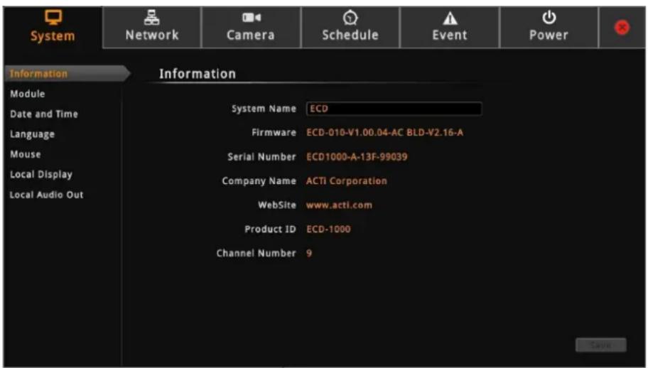
The system information is displayed.
- System Name: Name assigned to ECD-1000; can be modified. To modify the System Name, click the box and use the on-screen keyboard to enter the characters.
NOTE: The system name can be up to 10 alphanumeric characters only.
- Firmware: System firmware version.
- Serial Number: Product serial number.
• Company Name: Name of ECD-1000 manufacturer.
• Product ID: Product model name. - Channel Number: Maximum number of supported cameras.
Module
The Module page allows you to select the maximum number of cameras that you can view through ECD-1000. Options are: 4-channel, 9-channel (default mode), 12-channel, and 16-channel.
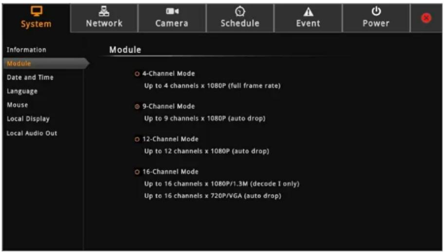
To ensure video stream performance, take note of the Decoding Limitation on page 13.
Date and Time
The Date and Time page allows you to manually change the system date and time or sync with an NTP server.
Automatically Set the Date and Time
Select the time zone to automatically set the date and time.
- On the Setup screen, click System > Date and Time.
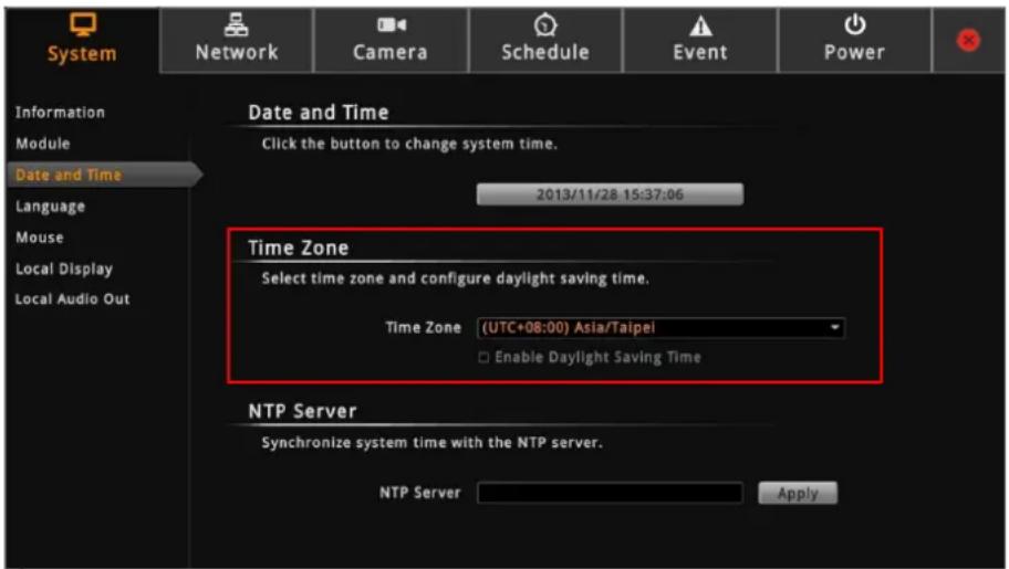
- On Time Zone, select the desired time zone. The system date and time automatically
changes according to the current date and time of the time zone.
- If applicable, check the Enable Daylight Saving Time box. Note that this box becomes enabled only if the Daylight saving time can be applied to the selected time zone.
Manually Change the Date and Time
- On the Setup screen, click System > Date and Time.
- Click the system date and time button.
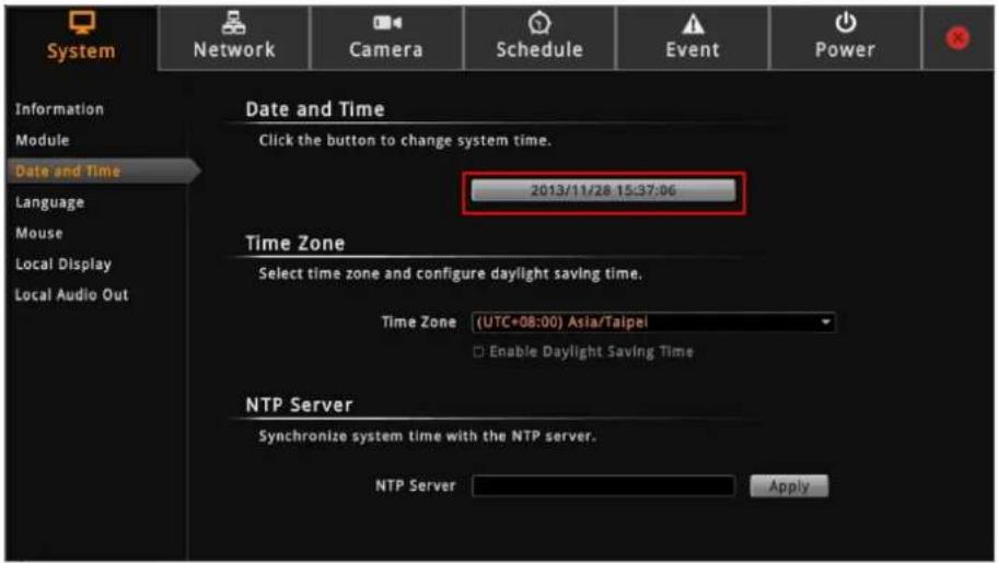
- Modify the date and time.

| Item | Description | |
| 1 | Month and Year | Select the month and year from the box. |
| 2 | Scroll Icons | Click to view the calendar of the previous or the next month. |
| 3 | Date | Click a date to set the date. Selected date is highlighted in orange, while the current date is in yellow. |
| 4 | Time | Select the hour, minute, and second from the corresponding boxes. |
- When done, click OK to save.
Sync Date and Time with NTP Server
- On the Setup screen, click System > Date and Time.
- On NTP Server, type the URL address of the NTP server.
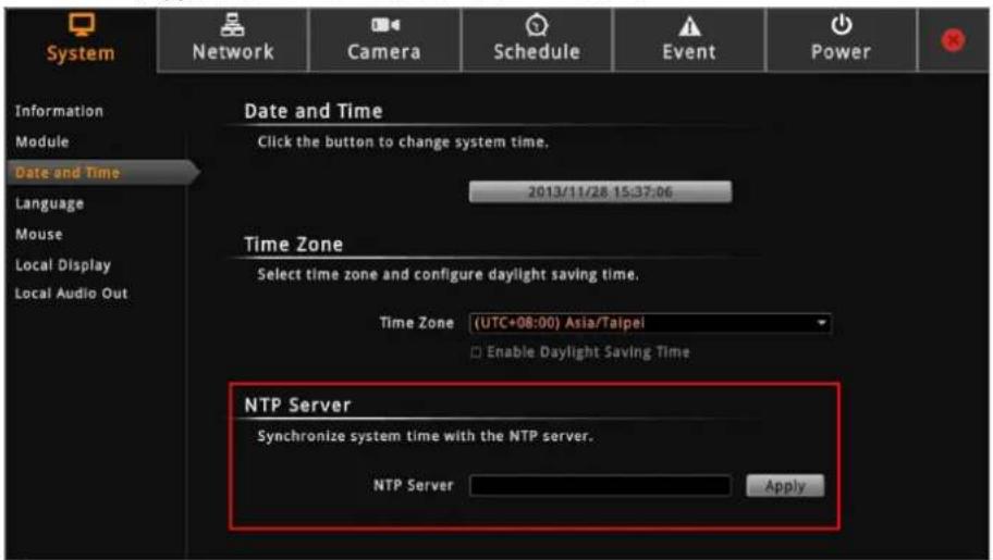
- Click Apply. A message will appear to confirm if synchronization is successful.
NOTE: If the NTP Server is a domain name, make sure the IP setting and DNS setting of the system gateway are correct.
To delete NTP Server
To delete an NTP server, delete the URL address on the field and click Apply.
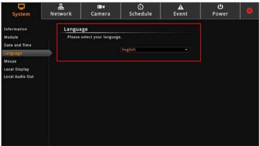
Language
To change the user interface language, click System > Language on the Setup screen. Then, select the desired language from the box.
Mouse
Click System > Mouse.
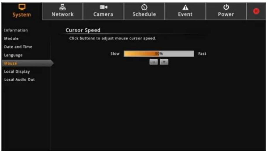
Click “-” to reduce the mouse cursor speed or “+” to increase the speed one notch at a time. Click and hold “-” or “+” to continuously reduce or increase speed.
Local Display
The Local Display allows users to show or hide information, such as the IP address, system date and time, or event trigger icons, on the Live View screen.
On the Setup screen, click System > Local Display.
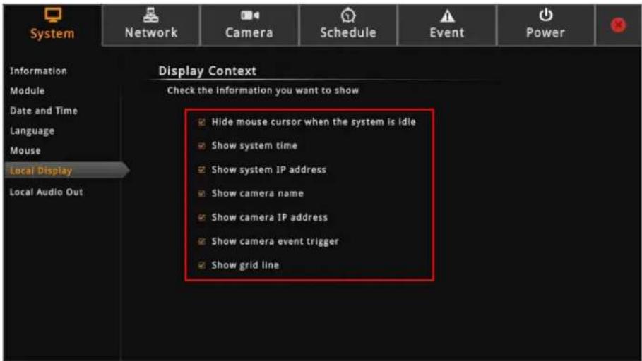
By default, all options are enabled. To disable a function, remove the check from its corresponding box.
- Hide mouse cursor when the system is idle: If checked, the mouse cursor is hidden
from the Local display if there is no mouse movement within 5 seconds.
- Show system time: If checked, the system date and time is displayed on the bottom of the Live View screen.
- Show system IP address: If checked, the system IP address is displayed on the bottom of the Live View screen.
- Show camera name: If checked, the camera name is displayed on the upper left corner of the channel.
- Show camera IP address: If checked, the camera IP address is displayed on the upper left corner of the channel. For security reasons, it is recommended to uncheck this function to hide the IP address from showing on the local display.
- Show camera event trigger: If checked, an event trigger icon, such as motion detection, will appear on the upper right corner of the channel when an event occurs.
- Show grid line: If checked, the lines separating the camera channels are displayed on the Live View screen.
Local Audio Out
By default, all the channels are muted. You can play the audio recorded by a specific channel via HDMI cable.
On the Setup screen, click System > Local Audio Out.
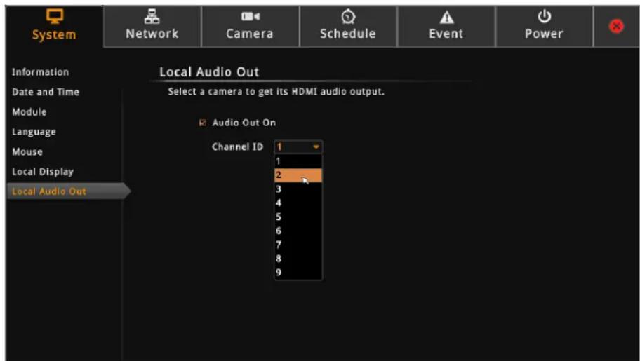
Enable "Audio Out On" and then select the channel from Channel ID list.
2.7 Configuring Network Settings
Viewing the Network Information
On the Setup screen, click Network.
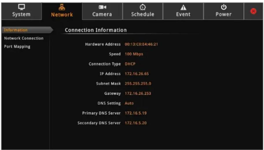
The network information, such as the Hardware Address (MAC address), Speed,
Connection Type, IP Address, Subnet Mask, Gateway, DNS Setting, and Primary and
Secondary DNS Server are displayed.
Configuring the Network Connection
Use the Network Connection to configure the network settings of ECD-1000, which includes setting of the connection type and IP address.
There are two types of connection: Manual and DHCP.
- Manual: The IP address must be assigned manually, so are other network configurations like Subnet Mask, Gateway, etc. Note that the IP address must be unique for each device on the network. By default, ECD-1000 has a default IP of 192.168.0.200 and subnet mask of 255.255.255.0. Users may need to change the default IP and subnet mask to ensure ECD-1000 belongs to the same network segment as the cameras.
- DHCP Connection: On a DHCP network, the DHCP server assigns the IP address automatically. By default, ECD-1000 will automatically switch to DHCP connection mode and be assigned an IP address. However, if this does not happen, users need to manually change the Connection Type to DHCP. See Obtaining the IP Address Automatically on page 51.
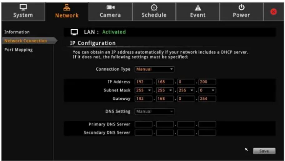
Setting the IP Address Manually
If your network does not have a DHCP server, perform the following to manually configure the network settings:
- On the Setup screen, click Network > Network Connection.
- On Connection Type, select Manual.
- Obtain the information from your network service provider and enter the IP Address, Subnet Mask, and other necessary settings.
NOTE: The IP Address and Subnet Mask must be filled in. Other settings may be left blank if not required by the network service.
- When done, click Save.
Obtaining the IP Address Automatically
If your network has a DHCP server, ECD-1000 will automatically be assigned an IP address. However, in case ECD-1000 does not detect the DHCP connection, perform the following procedures to obtain the IP address:
- On the Setup screen, click Network > Network Connection.
- On Connection Type, select DHCP.
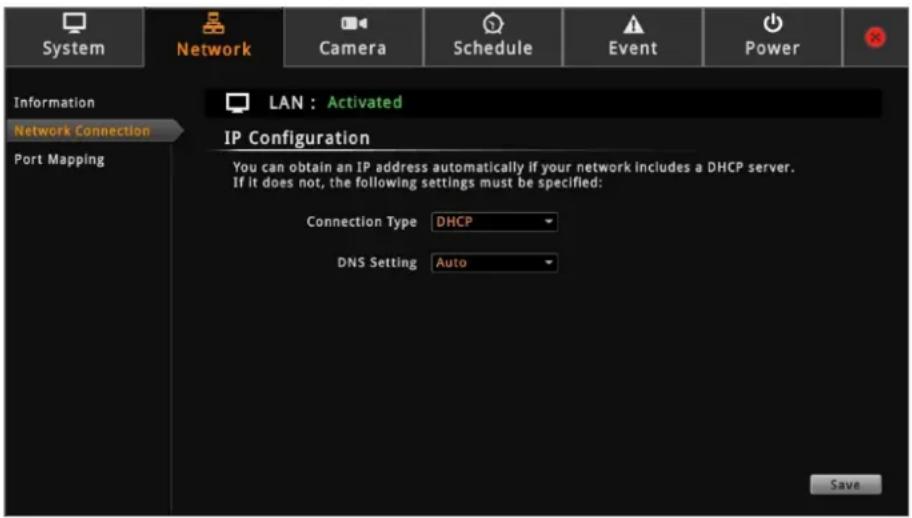
- Leave the default DNS Setting as "Auto".
- Click Save. Connection is complete when LAN shows "Activated".
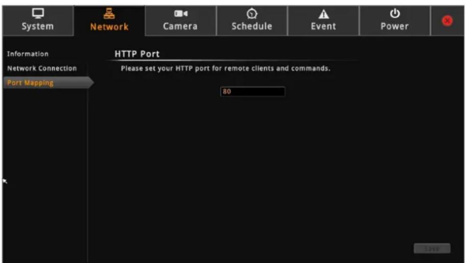
By default, ECD-1000 port number is 80. To change this value, click Network > Port Mapping on the Setup screen.
2.8 Configuring the Cameras
The Camera Setup Page
On the Setup screen, click Camera.
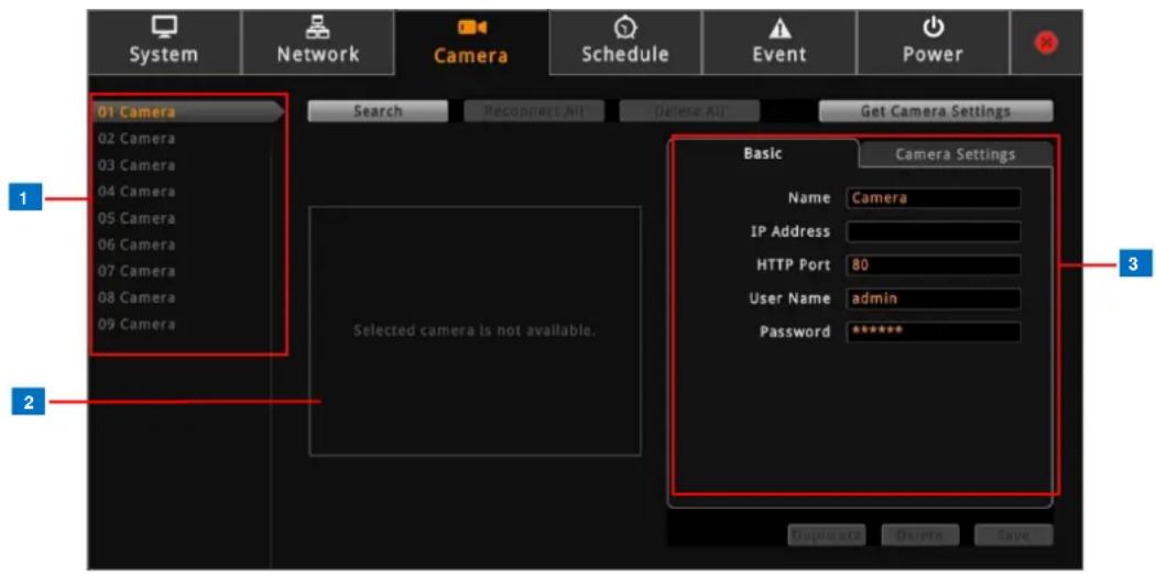
| Item | Description | |
| 1 | Camera List Panel | Displays the camera name. Click a channel to view its display and settings. |
| 2 | Display Window | Displays the current live view of the selected camera. |
| 3 | Camera Properties | Displays the camera connection and streaming properties. It has two page tabs:Basic: Displays the connection properties, such as the IP address, HTTP port, User Name (account) and Password used to access the camera. You can also use this page to manually add a camera by entering these properties. See Adding Cameras on page 53.Camera Settings: Displays the camera video streaming properties, such as Channel ID, Resolution, Encoder, etc. These properties can be modified on ECD-1000 and will also take effect on the camera side. See Modifying Camera Settings on page 61. |
Adding Cameras
There are three ways to add cameras for viewing:
●By automatically searching the cameras on the network
●By manually entering the IP address of the camera
- By manually entering the IP address of an ONVR-compliant camera
- By manually entering the IP address of the camera and connect via RTSP protocol
NOTE: ECD-1000 supports third-party cameras. To validate specific camera models that can be integrated, visit our website (http://www.acti.com/3rdpartycamera).
Searching Cameras to Add
If you do not know the IP address of the camera or you want to add several cameras at the same time, you can search the cameras connected to the network and choose up to 4, 9, 12 or 16 cameras to connect to ECD-1000. The maximum number of cameras to be added varies depending on the selected module (see Module on page 44).
- On the Setup screen, click Camera.
- Click Search or an empty channel number from the left panel. The Add Camera screen appears.
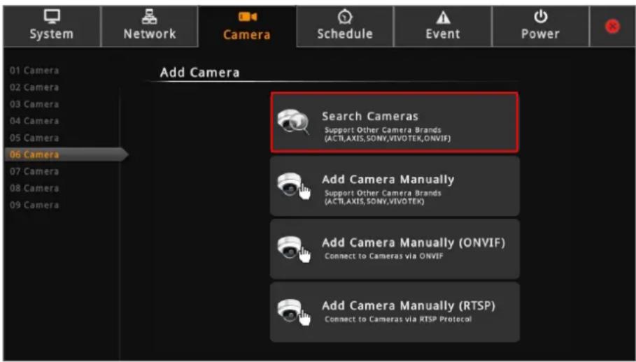
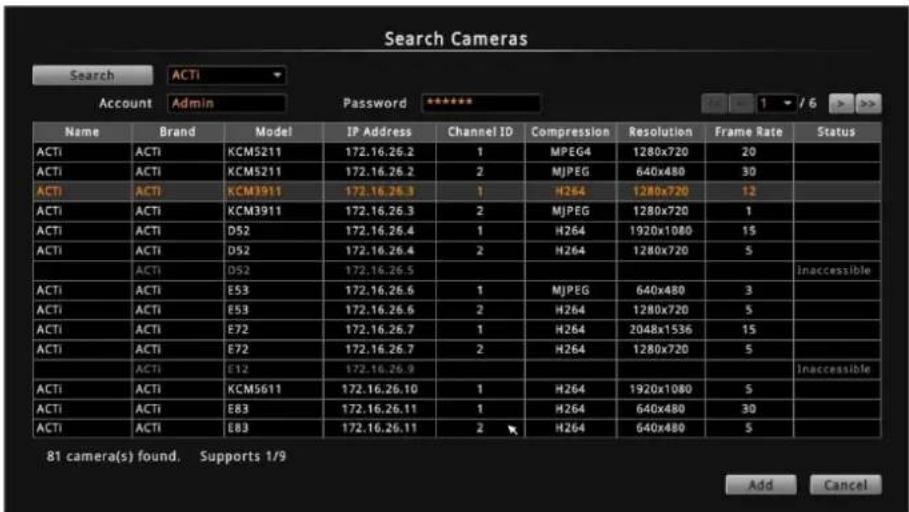
- Click Search Cameras. The Search Cameras screen appears.
- By default, the camera manufacturer, user account name and password for access are already filed with ACTi default values. If you want to add camera from other manufacturers or the camera has different account and password, modify these values as needed. The cameras connected on the network are listed.
NOTE: ECD-1000 supports third-party cameras. To validate specific camera models that can be integrated, visit our website (http://www.acti.com/3rdpartycamera).
- Click one or more cameras to select. Selected cameras appear in orange text.
NOTE: The Status column shows the status of the camera:
- Inaccessible: The camera account or password may be different from what you have entered on Account and Password fields. So that camera cannot be accessed.
-
In Use: The camera is already added to ECD-1000 for live viewing.
-
Click Add to add the selected cameras to ECD-1000 for live viewing. The cameras are then displayed on the Camera List panel.
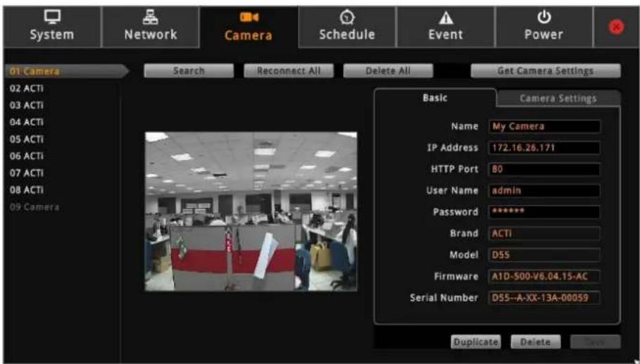
- Click ✗ to close the Setup screen. The Live View screen displays the live view of the selected cameras.
Adding Cameras Manually
In case of adding a camera from outside the local area network or over WAN, use the add camera manually function. You need to know the IP address, HTTP port, User Name and Password of the camera you want to connect to.
- On the Setup screen, click Camera.
- Click on an empty channel number from the left panel, and click Add Camera Manually.
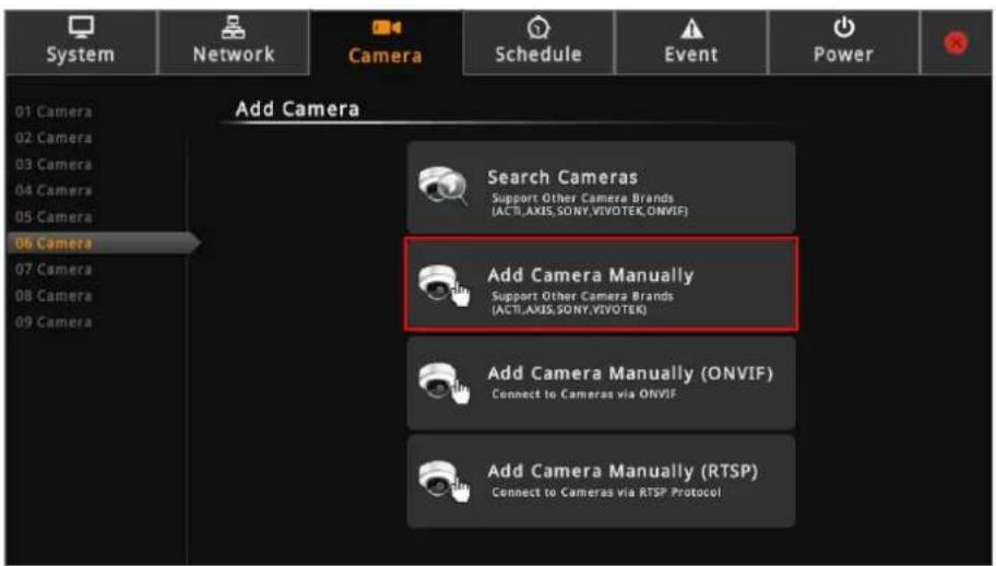
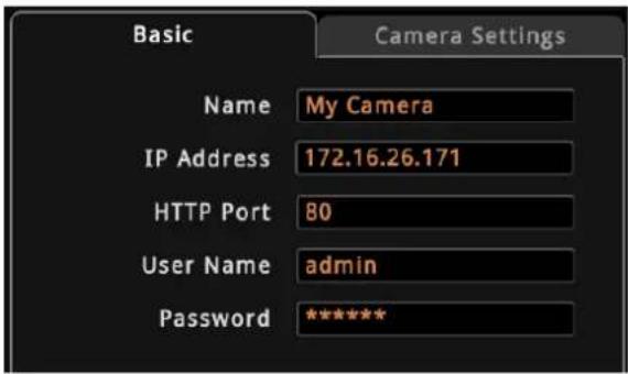
- On Name, type a name you want to use to identify the camera (maximum of 32 alphanumeric characters, no spaces nor symbols). This name is saved only on ECD-1000 and does not affect the settings on the camera side.
- Enter the IP Address, HTTP Port, User Name and Password of the camera you want to connect to.
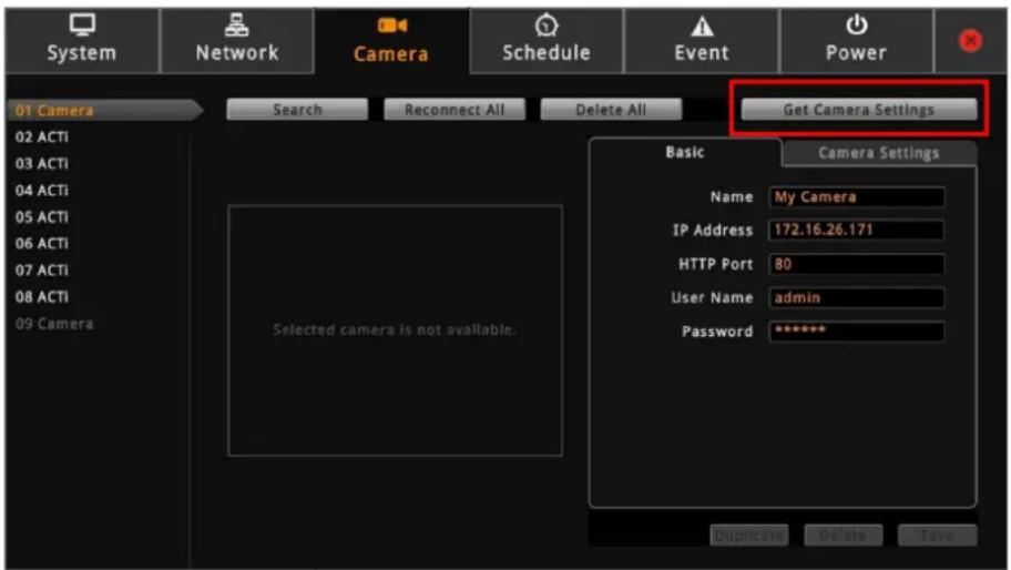
- Click Get Camera Settings. ECD-1000 connects and retrieves the camera settings. At this point, nothing is shown on the Display window yet.
- Click Save.
Once camera settings are saved, the camera Live View is shown on the Display window.
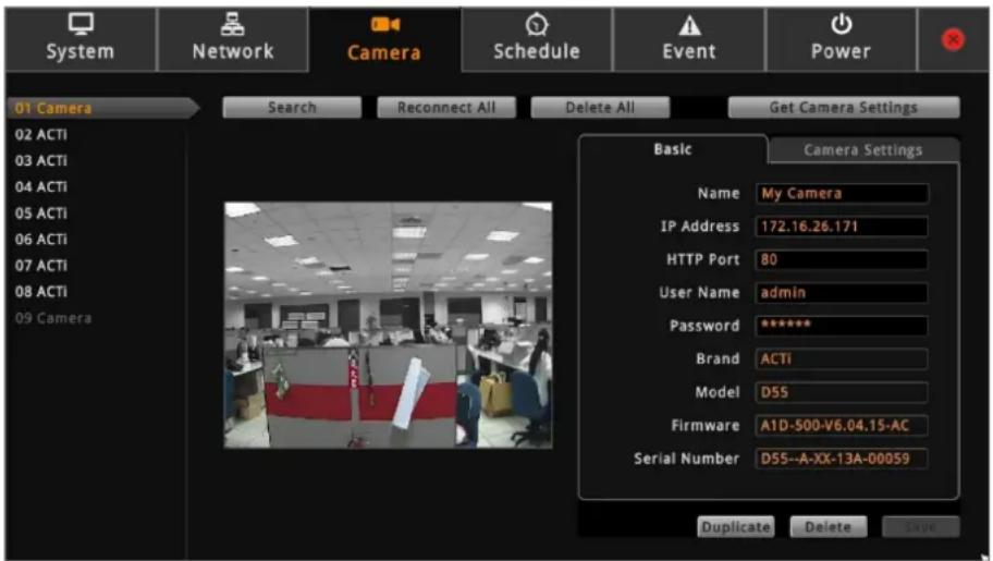
TIP: Use the Duplicate button to add another camera with almost similar camera settings to another channel, see Duplicating Cameras on page 59.
Adding ONVIF-Compliant Cameras Manually
With Add Camera Manually (ONVIF) function, you can add any camera regardless of its brand as long as it is ONVIF-Compliant.
- On the Setup screen, click Camera.
- Click on an empty channel number from the left panel, and click Add Camera Manually (ONVIF).
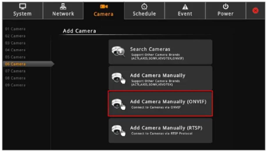
- On Name, type a name you want to use to identify the camera (maximum of 32 alphanumeric characters, no spaces nor symbols). This name is saved only on ECD-1000 and does not affect the settings on the camera side.
- Enter the IP Address, HTTP Port (by default 80), Account and Password of the camera you want to connect to.
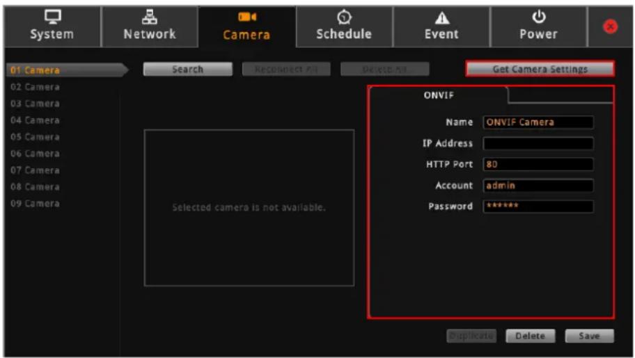
- Click Get Camera Settings. ECD-1000 connects and retrieves the camera settings. At this point, nothing is shown on the Display window yet.
- Click Save. Once camera settings are saved, the camera Live View is shown on the Display window.
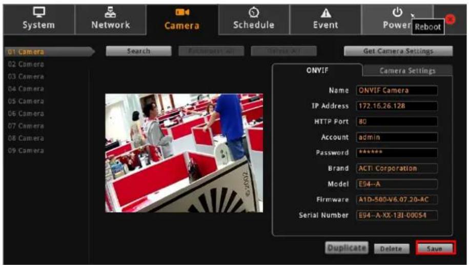
TIP: Use the Duplicate button to add another camera with almost similar camera settings to another channel, see Duplicating Cameras on page 59.
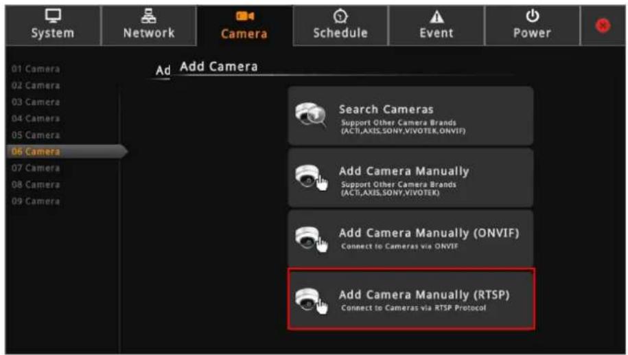
Adding Cameras Manually via RTSP
In case you want to add cameras via Real Time Streaming Protocol (RTSP), use the Add Camera Manually (RTSP) function. This feature is useful when adding third party cameras which support the standard RTSP.
- On the Setup screen, click Camera.
- Click on an empty channel number from the left panel, and click Add Camera Manually (RTSP).
- On Name, type a name you want to use to identify the camera (maximum of 32 alphanumeric characters, no spaces nor symbols). This name is saved only on ECD-1000 and does not affect the settings on the camera side.
- Enter the IP Address, URI (Uniform Resource Identifier), RTSP Port (by default 554), Account and Password of the camera you want to connect to and select the streaming protocol.
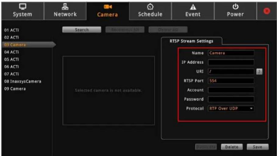
TIP: If you do not know the URI of the camera, click to select from the most common manufacturers on the list. Once a manufacturer is selected, its URI is filled up on the field. If the predefined URI does not work, check the camera specifications for details.
5. Click Save.
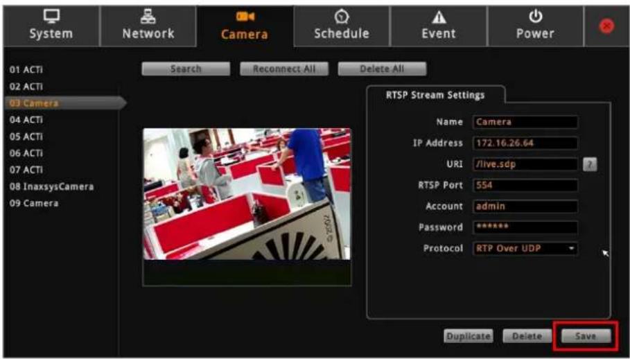
TIP: Use the Duplicate button to add another camera with almost similar camera settings to another channel, see Duplicating Cameras on page 59.
Duplicating Cameras
Use this function to add another camera with almost the same camera settings as the selected camera. So instead of entering all the information one by one, duplicate the camera settings first and then modify afterwards. However, to use this function, there must be at least one available channel without a connected camera.
- On the Camera page, select the camera you want to duplicate on the Camera List panel, and then click Duplicate.
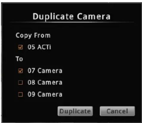
- Available channels are shown under To. Check the box(es) of the channel(s) to copy the camera settings to.
- Click Duplicate.
Modifying Camera Settings
In some cases, you may need to modify the camera connection and streaming properties. To do this, follow the procedures below:
- On the Setup screen, click Camera.
- Select the camera from the Camera List panel.
- Click Get Camera Settings.
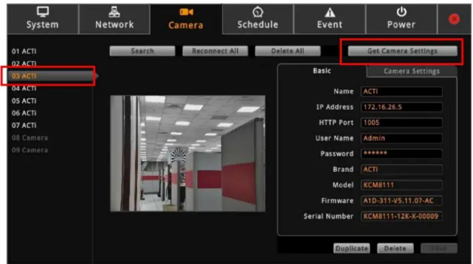
- To modify the connection properties, click the Basic tab. Modify the Name, IP Address, HTTP Port (port used by remote IE clients), User Name and Password, as needed.
NOTE: The Name is the camera name displayed on ECD-1000. This name is not saved or shown on the camera side. The maximum length is 32 alphanumeric characters, symbols are not allowed. In case of a space in between the characters, ECD-1000 automatically removes that space.
- To modify streaming properties, click the Camera Settings tab, and modify the settings.
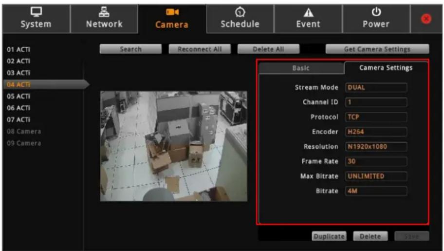
| Item | Description |
| Stream Mode | Displays whether the camera has Single or Dual stream mode. This field is not editable. |
| Channel ID | For dual stream cameras, select the stream to view. Usually, stream 1 or Channel ID 1 is configured to be the best quality stream for Network Video Recorder (NVR) recording purposes and stream 2 or Channel ID 2 with basic quality for live viewing on the NVR and ECD-1000. Once the Channel ID is selected, the succeeding camera properties, such as encoder, resolution, etc., change according to the compression settings of the selected stream. |
| Protocol | Displays the video stream protocol. You can modify the video stream protocol, as needed. |
| Encoder | Displays the video stream encoder type. You can modify the encoder type for the current stream, as needed. Note that for local viewing, only H.264 is supported. |
| Resolution | Displays the video stream resolution. You can modify the resolution, as needed. Note that for local viewing, only up to 2 megapixels (1920 x 1080) is supported. |
| Frame Rate | This is the amount of frame per second of the video stream. You can modify the frame rate, as needed. |
| Bitrate Mode | Under “Constant Bit Rate” mode (CBR), the camera keeps the stable bitrate regardless of the complexity of the scene. Under this mode, the video quality may vary if the bit rate value is set too low. It is easier to do storage and network bandwidth consumption estimations under this mode compared to Variable Bit Rate mode.Under “Variable Bit Rate” mode (VBR), the camera will keep the video quality stable while the bit rate may occasionally go up or down, depending on the complexity of the scene. |
| Max Bitrate(only for H.264) | The bitrate will be floating slightly under that limit. For example, if the limit is set as 2M, the bitrate will be floating around 1.6~2.0 Mbps. If the Max Bitrate is “Unlimited”, then the Bitrate selection box will appear that defines the bit rate level. |
| Bitrate(only for H.264) | When Max Bitrate is “Unlimited”, the user can define the AVERAGE bit rate. For example, if the Bitrate is 2M, then occasionally, the actual bit rate may go below or beyond 2M, butin the long run, the average bit rate will be very close to 2M. This mode allows the most accurate storage estimations, however, while planning the bandwidth, please consider the occasional peaks of bit rate. |
| Video Quality(only for MJPEG) | The user can define the quality with the numeric scale from 1 to 100. The default MJPEG quality is 60. The higher is the quality level, the more bit rate the camera will use to achieve the target quality. However, note that local Live View cannot display streams other than H.264. |
| Quality(only for H.264) | Under VBR mode, the bit rate will be floating while the video quality will be stable and follows the quality standard set by the user. The user can choose either “High”, “Medium” or “Low” quality. The higher is the quality level, the more bit rate the camera will use to achieve the target quality. |
| GOP 1 I-Frame | Under VBR mode it is possible to adjust the GOP length - that is the occurrence rate of I-frames. By default, there is one I-frame per second. For example, in case of 30fps, there will be 1 I-frame and 29 P-frames every second by default. When the GOP is changed to “1 I-frame per 5 seconds”, then there will be one I-frame, followed by 149 P-frames. In case of the static scenes, long GOP can further minimize the bandwidth and storage consumption. |
- When done, click Save. The camera properties are saved and ECD-1000 restarts the connection.
Reconnecting Cameras
If there is a need to refresh the camera connection, click Reconnect All. All the cameras will be reconnected.
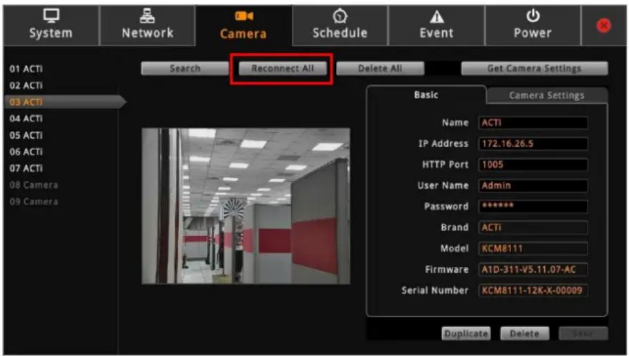
NOTE: All video streams will be lost for a few seconds until the reconnection is finished.
Deleting Cameras
Cameras can be removed one at a time or all cameras at the same time.
On the Setup screen, click Camera.
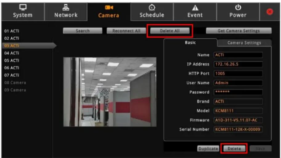
- To remove a camera, click the camera from the Camera List panel, and then click Delete.
- To remove all the cameras at the same time, click Delete All.
2.9 Managing Network Loss Event
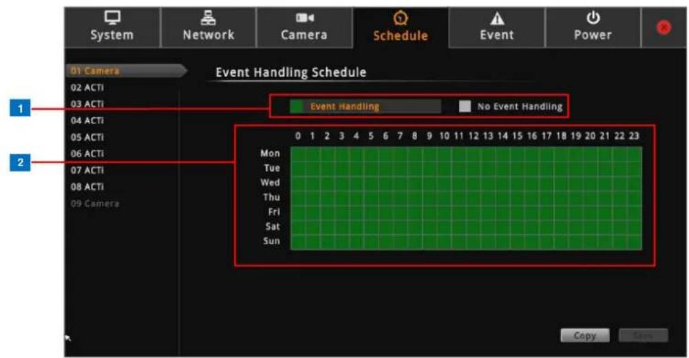
When a camera or a ECD-1000 suddenly disconnects from the network, ECD-1000 will trigger a network or video loss notification icon on the Live View channel window and will beep. By default, the trigger is enabled for 24 hours a day and 7 days a week. However, the beep sound must be enabled and configured separately.
Scheduling Network / Video Loss Trigger
- On the Setup screen, click Schedule.
- Select the camera from the camera list panel.
| Item | Description | |
| 1 | Event HandlingSchedule | • Event Handling: Enables event trigger.• No Event Handling: Disables event trigger. |
| 2 | Time Table | Shows green cell if event trigger is enabled and gray cell if event trigger is disabled. |
-
Select either Event Handling or No Event Handling.
-
Drag the mouse over the time table to select the day and time period.
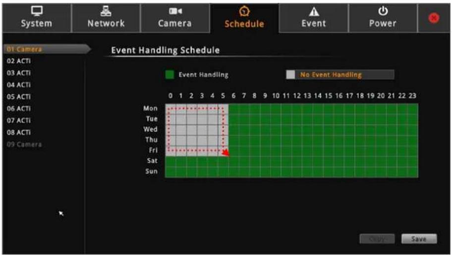
- When done, click Save.
TIP: Instead of manually modifying the event trigger on all cameras, users can copy the schedule to other channels. See Copying Event Schedule Settings on page 68.
Enabling Beep Sound Trigger
To enable the beep sound when a camera is disconnected from the network or when an encoder loses its video source, do the following:
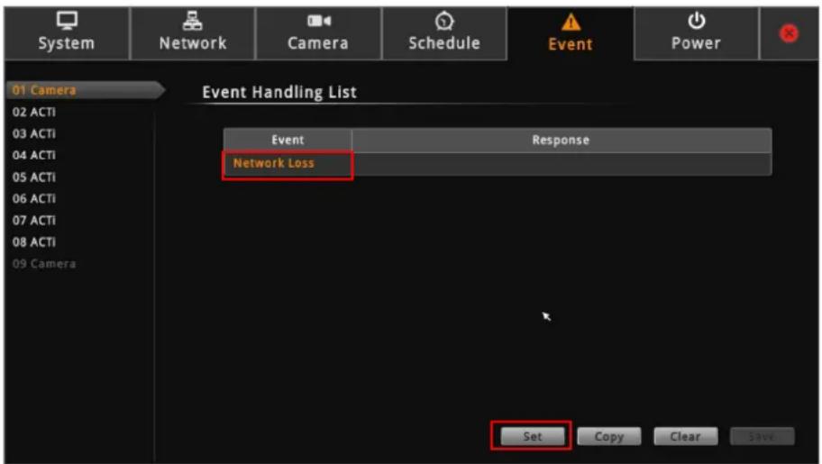
- On the Setup screen, click Event.
- Click Network Loss or Video Loss, and then click Set.
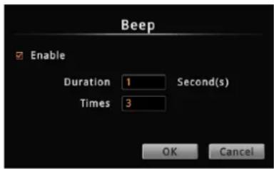
- Check Beep to enable the beep sound.
-
Set the beep duration and the number of beeps to sound when the event is triggered.
-
Click OK.
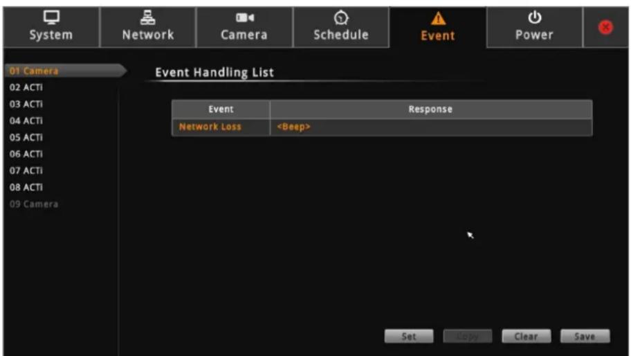
- Click Save to save the configurations. ECD-1000 will demonstrate and emit the beep sound as configured.
Copying Event Schedule Settings
Instead of manually modifying the event schedule and beep settings on all cameras one by one, users can copy the settings to other channels.
- After setting the event schedule or beep settings, click Copy. The Copy Schedule window appears.
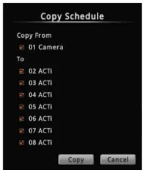
- Check to select the camera(s) under To.
- Click Copy. The current camera event schedule or beep settings will be copied to the selected camera(s) under To.
- A message appears when copy is complete. Click OK to close the window.
2.10 Rebooting the Device
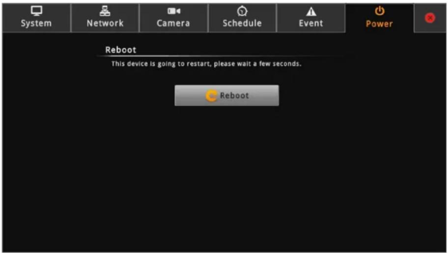
- On the Setup screen, click Power.
- Click Reboot.
- When the confirmation message appears, click OK to restart.
NOTE: All video streams will be lost for a few seconds until ECD-1000 completes the reboot process.
Chapter 3: Remote Management
This chapter describes ECD-1000 operation and management on a Remote Client side. It contains the following topics:
- Accessing the Device: Describes the setup procedures involve when accessing ECD-1000 for the first time through a computer on the network. This includes changing ECD-1000 IP address and adding the cameras.
- The Live View Screen: Describes how to use the Live View screen, changing the layout, channel patrolling, resetting the channel position, and syncing local and remote display layout.
- Accessing the Setup Screen: Provides an overview of the Setup menu.
- Configuring System Settings: Describes how to view and modify the system settings such as date and time, language, and how to filter information shown on the local display.
- Configuring Network Settings: Describes how to modify the IP configurations, port mapping and other network settings.
- Configuring the Cameras: Describes how to add and view the cameras and manage the camera settings.
- Configuring User Access: Describes how to add groups and users who can access the Setup screen and limit the type of access granted to each group.
- Viewing the System Log: Describes the information shown on the System Log page.
- Rebooting the Device: Describes how to do a system reboot.
3.1 Accessing ECD-1000 Remotely
In most cases, it is recommended to perform the initial configurations, before ECD-1000 is even mounted to its location, using local access. This is because of the limitation of ECD-1000 to decode some video resolution and compression. If monitoring will be mainly done on a local display, it is recommended to directly test and view the camera live view on the local display to ensure the video stream properties are supported for local display. Note that streams higher than 2 megapixels (MP) or encoder other than H.264 can be properly viewed on a remote client (i.e. Web Client) but cannot be viewed on the local display. After the initial configurations and installation, further management or advanced security settings may be done through remote access by a client computer with web browser (supports Internet Explorer only).
How to Access ECD-1000?
Accessing From a Network with DHCP Server
If the network has a DHCP server, the DHCP server automatically assigns the IP address to ECD-1000. There are several ways to access ECD-1000, options are:
- From Windows, click Start > Computer > Network. Double-click on ECD-1000 model to open the user interface on the web browser.
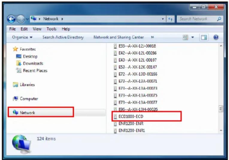
NOTE: Set the computer default web browser to Internet Explorer to use this feature.
- From IP Utility (downloaded from the website www.acti.com), click the IP address of ECD-1000 to open the user interface on the web browser.
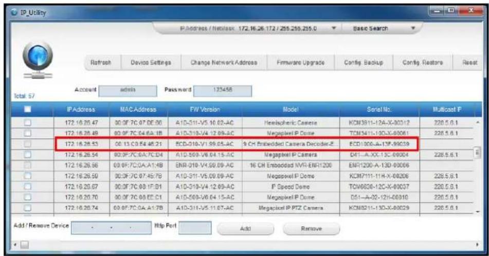
- If you already know the IP address of ECD-1000, open the web browser and directly type the IP address on the address bar.

TIP: The quickest way to know the IP address of ECD-1000 is to check the local display. The IP address is shown on the bottom of the Live View screen.
Accessing From a Network without DHCP Server
The default IP address of ECD-1000 is 192.168.0.200. If the network does not have a DHCP server, then this is the IP address of ECD-1000, whereas the default port number is 80. Take note that the computer must be within the same network segment. For example, the computer must have an IP address of 192.168.0.X (where X is any number between 1 \~ 255, except 200) and Subnet Mask of 255.255.255.0.
For example, based on Windows 7, configure the IP address to 192.168.0.99 and set Subnet Mask to 255.255.255.0 by using the steps below:
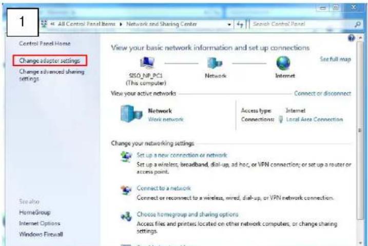
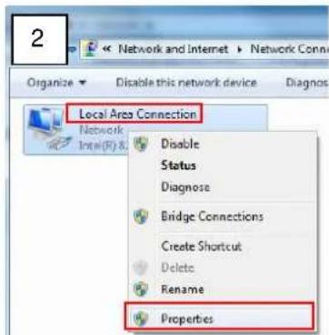
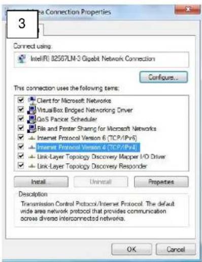

To access ECD-1000, open the web browser and type the default IP address on the address bar:
192.168.0.200

The Login Screen
When logging in for the first time or after a firmware upgrade, users will be prompted to install required ActiveX components. Follow the on-screen instructions to install the ActiveX components.
When prompted to login, enter the default Account and Password and click Login.
Account: admin
Password: 123456
For security purposes, it is recommended to modify the password in the Setup Wizard or see 3.7 Configuring User Access on page 114.
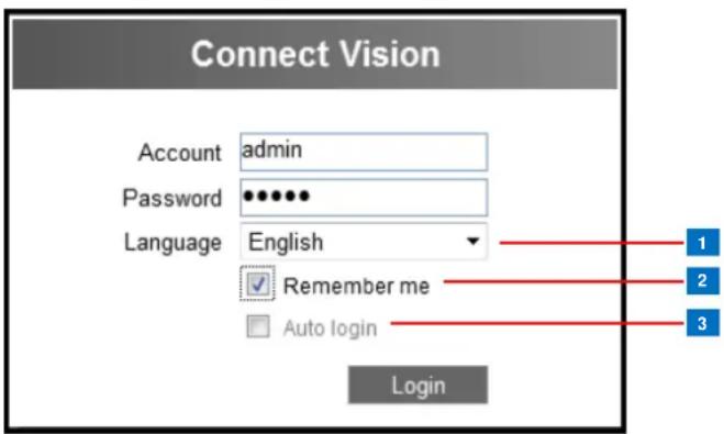
| Item | ||
| 1 | Language | The default user interface language is English. To change the language, select the preferred language from the box. |
| 2 | Remember Me | Check to allow the system to remember the account name.Users just need to enter the password to login. |
| 3 | Auto Login | Check to skip the login page and go directly to theLive Viewscreen every time the user logs in from the current computer.This feature takes effect on the succeeding log in.NOTE:This can be a security risk for any other user will be able to access ECD-1000. |
The Setup Wizard
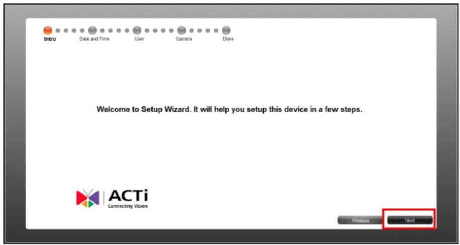
When accessing ECD-1000 for the first time on a client computer, the Setup Wizard appears to facilitate easy camera connection. All settings can still be modified in the Setup screen.
1. Click Next.
-
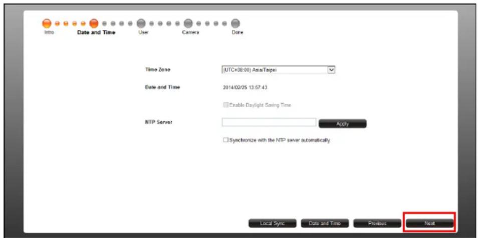
Set the date and time by one of the following options:
-
Select the Time Zone.
- Sync with an NTP Server.
- Click the Local Sync button to sync with the client computer date and time.
- Click the Date and Time button to set the date and time manually.
-
Click Next to continue.
-
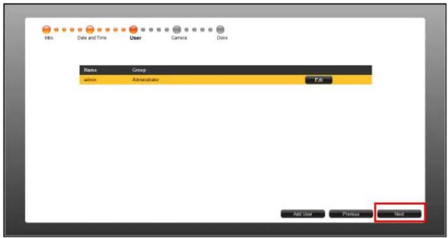
The default User is "admin" and the Password is "123456". To modify the password, click Edit. Or, click Next to continue.
- By default, the camera manufacturer, user account name and password for access are already filed with ACTi default values. If you want to add camera from other manufacturers or the camera has different account and password, modify these values as needed. Then, click Search to search for cameras.
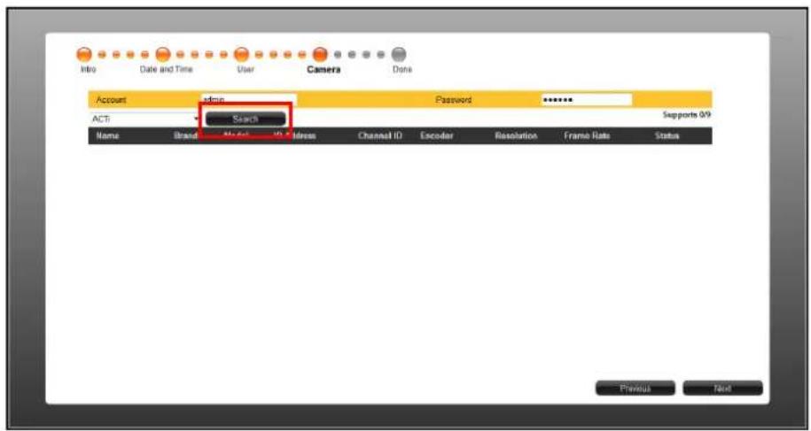
NOTE: ECD-1000 supports third-party cameras. To validate specific camera models that can be integrated, visit our website (http://www.acti.com/3rdpartycamera).
- The list of cameras connected on the network appears. Click on a camera to select it. By default, you can select up to 9 cameras to add. Selected cameras are highlighted in orange.
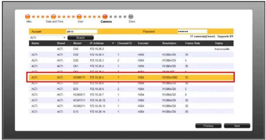
- Click Next to continue.
- Click Done to close the wizard.
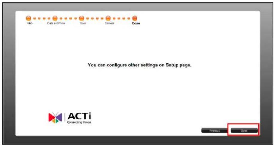
3.2 The Live View Page
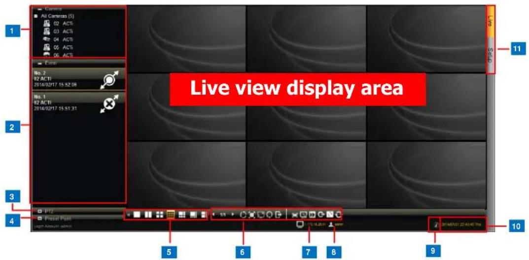
| Item | Description | ||
| 1 | Camera List | Displays the channel number and camera name of the cameras connected to ECD-1000. Drag a channel to a window on theLive Viewdisplay area to view the video stream. Or, double-clickAll Camerasto automatically view all cameras on the list to theLive Viewdisplay area. SeeViewing the Camerason page 80. | |
| 2 | Event List | Displays connection and event notifications. | |
 | Indicates the camera has been connected. | ||
| [246C] | Indicates the camera is disconnected. | ||
| [2276] | Indicates motion is detected. The number indicates the area where motion is detected. Motion detection settings are done on the camera side. | ||
| 3 | PTZ Control | Displays the PTZ control panel and allows users to pan, tilt, and zoom on the channel using the PTZ control buttons, as well as adjust the PTZ settings and adjust the focus. See2.4 Using the PTZ Control Panelon page 35. | |
| 4 | Preset Point | Allows users to define preset points and set the tour of PTZ camera models. SeeSetting Preset Pointson page 37. | |
| 5 | Layout Icons | Click an icon to change the layout of channels. The current layout is indicated by an orange icon. Moving the mouse over the icon displays the icon name. SeeChanging the Window Layouton page 82. | |
| 6 | Viewing Icons | Use for managing the display settings or the sequence patrol. SeePatrolling Channelson page 83. | |
 | The number indicates the current page view over the total number of pages that can be viewed. Click the left or right arrow to go back or go to the next page manually. | ||
| [K70H] | Click to start / stop sequence patrol. | ||
| [S2DD] | Click to stretch/ un-stretch the video | ||
| [A6S4] | Click to enter / exit full screen. | ||
 | Click to reset the channel position | ||
 | Click to hide / reveal the blue title bar of each channel | ||
 | Click to disconnect all channels | ||
 | Click to switch betweenDecode I-frame/Auto Drop Frame modes. By default the live view usesAuto Drop Frame mode, which will set random channels to decode I frame only so as to lower the client computer's CPU loading. By switching toDecode I-frame mode, all channels will display at 1 FPS. | ||
 | Close the current browser | ||
 | Logout and enter the Login window | ||
 | Click to sync the remote display according to the local client display. | ||
 | Click to sync the local display according to the remote client display. | ||
| 7 | [270A] | Your user account | |
| 8 |  | The IP address of ECD-1000 | |
| 9 | [AZZY] | Click to view the firmware version. | |
| 10 |  | The system date and time. Click the date and time to access the Date and Time menu. | |
| 11 | Screen Switch | Click to switch betweenLiveandSetupscreens. | |
Viewing the Cameras
There are several ways to view cameras on the Live View screen.
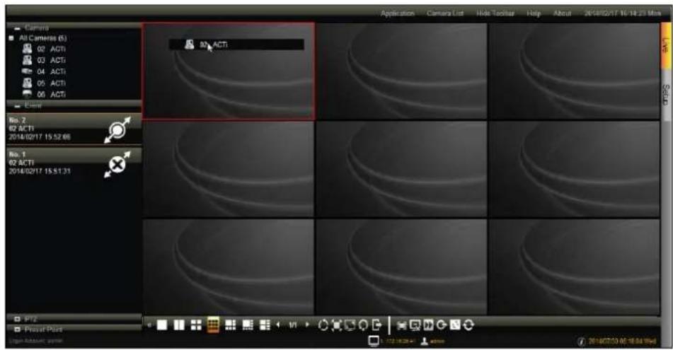
- Drag a camera from the list to a channel window to view it on the Live View display area.
- Double-click a camera from the list to view it on the next available channel window.
- Double-click All Cameras to view all cameras on the Live View display area.
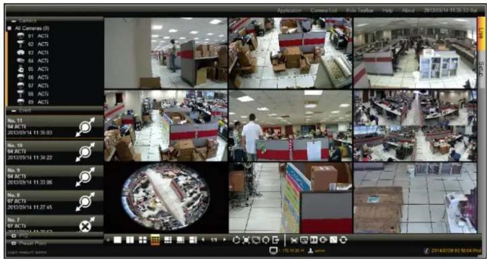
NOTE: ECD-1000 does not save the displayed channel settings; so every time users access ECD-1000, the Live View display area is empty and cameras must be added to the Live View display area again.
Viewing Channels in Full Screen
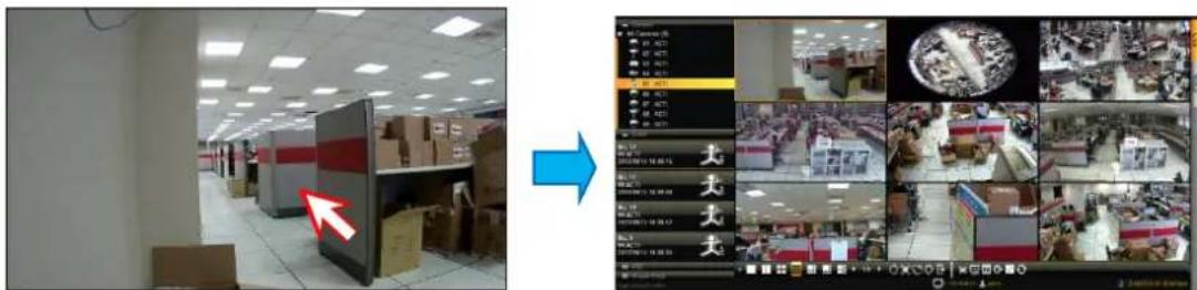
Double-click a channel to view the channel in full screen.
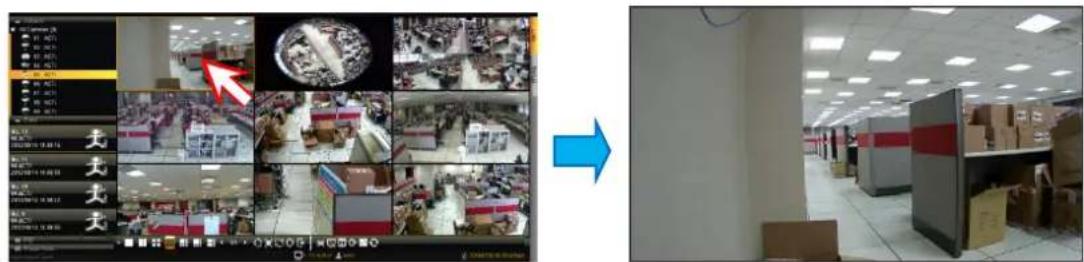
Double-click again to switch back to the previous layout.
Zooming In
With the mouse icon over the channel window, scroll the mouse wheel up or down to zoom in or zoom out the image.
Or, to zoom in on an area, click and drag the mouse to box the area to magnify.
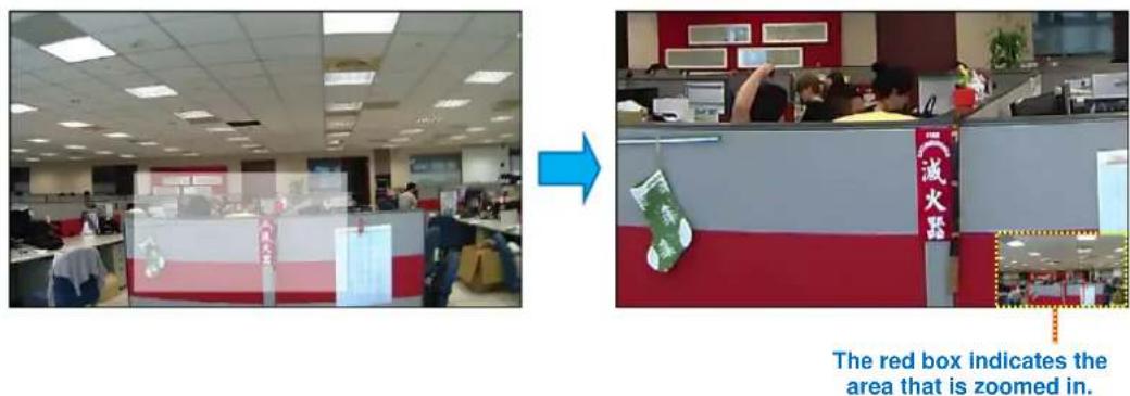
The whole camera view is shown on the lower right corner and the zoomed area is indicated by a red box.
See also, Using Optical / Digital PTZ on page 85.
Changing the Window Layout
By default, the Live View is displayed with a 9-channel layout. The layout can be changed into a 1-channel, 2-channel, 1+7-channel display, etc.
| Layout 1 | Layout 2 | Layout 4 |
| Click to display one channel on full screen. | Click to display 2 channels at a time. | Click to display 4 channels at a time. |
 | 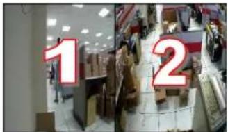 | 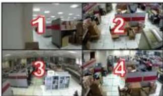 |
| Layout 9 | Layout 12 | Layout 16 |
| Click to display 9 channels at a time. | Click to display 12 channels at a time. | Click to display 16 channels at a time. |
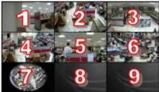 | 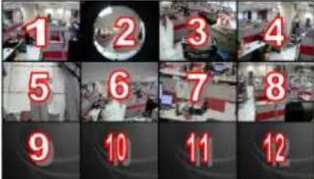 | 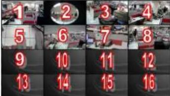 |
| Layout 1+5 | Layout 1+7 | Layout 1+12 |
| Click to display 6 channels at a time on a 1+5 layout. | Click to display 8 channels at a time on a 1+7 layout. | Click to display 13 channels at a time on a 1+12 layout. |
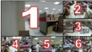 | 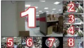 | 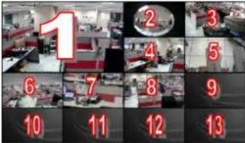 |
| Layout 2+4 | Layout 2+8 | |
Click to display 6 channels at a time on a 2+4 layout. 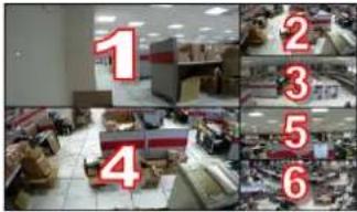 | Click to display 10 channels at a time on a 2+8 layout. 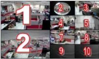 | |
To view succeeding channels, use the For example, if viewing on a 2-channel layout, and you want to view the next 2 channels, click Dr, click on the number and select the page to view.
Patrolling Channels
Instead of viewing all 9 channels at the same time, users may want to view one channel in full screen or two channels at a time and scroll through all the channels alternately. To do this, follow the procedures below:
- Select the desired window layout for patrolling (i.e. Layout 1 for full screen or Layout 2 for two channels at a time, etc.).
- Click ☐ to enter Patrol Time Setting window to set the patrol interval and click "OK" to start Sequence Patrol. By default, 3 seconds is the interval between changing one screen to another. If necessary, type a different number to modify the interval time.
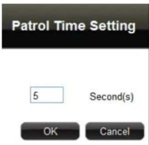
- Sequence Patrol starts. To stop the patrol, click again.

Syncing Remote and Local Live View Display
The displayed cameras and window layout on the remote client and local client can be synced.
- Click 📋 to sync the Live View based on the local client display. So instead of dragging the camera to a channel window on the Live View display area every time the user access
ECD-1000, click to simply view the cameras as how users will see it on the local client display. - Click 📋 to sync the local Live View based on the current remote client display.
Reconnecting the Cameras
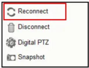
If there is a need to refresh the camera connection, right-click on the channel window of the camera, and click Reconnect.
NOTE: All video streams will be lost for a few seconds until the reconnection is finished.
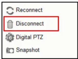
Removing Video Stream from Live View
To remove the video stream from showing on the Live View screen, right-click on the channel window of the camera, and click Disconnect.
Using Optical / Digital PTZ
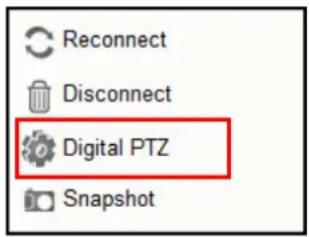
PTZ and zoom cameras have the option to toggle between optical and digital PTZ. Non-PTZ and non-zoom cameras can still have digital PTZ functions when viewed on remote clients.
For PTZ and zoom cameras, right-click on the channel window and click Digital PTZ or Optical PTZ to toggle between optical and digital PTZ.
NOTE: This function is disabled for non-PTZ and non-zoom cameras.
How to Use Optical PTZ
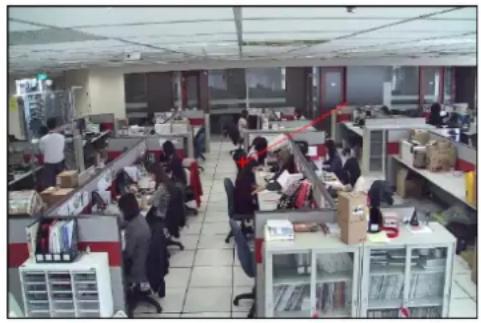
By default, PTZ and zoom cameras are on optical PTZ. A red cross-hair appears in the middle of the channel window when the camera is selected. Use the mouse or the PTZ Control Panel to do PTZ functions (see Using the PTZ Control Panel on page 87).
natural_image
Interior view of a busy open-plan office with employees at cubicles and desks (no visible text or signage)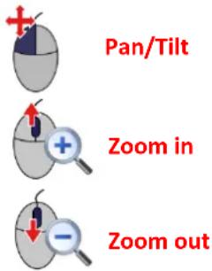
- To pan or tilt PTZ cameras, click the mouse anywhere on the Live View screen to move in that direction. The length of the direction indicator (red line) is proportional to the Pan and Tilt speed. The farther you place the cursor from the center, the faster the Pan/Tilt movement.
- To zoom in or zoom out, scroll the mouse wheel up to zoom in; scroll the mouse wheel down to zoom out the image.
When the channel is viewed on full-screen, the red cross-hair does not appear but pan, tilt and zoom functions can still be done the same way.
How to Use Digital PTZ
Digital PTZ can be done on the channel window and on full-screen view. For PTZ and zoom cameras, right-click the mouse button and toggle to Digital PTZ first.
- On the Live View, select the camera to highlight the channel window.
- Scroll the mouse wheel up or click and drag the mouse on an area to zoom in the image.
- The whole camera view is shown on the lower right corner and the zoomed area is indicated by a red box.
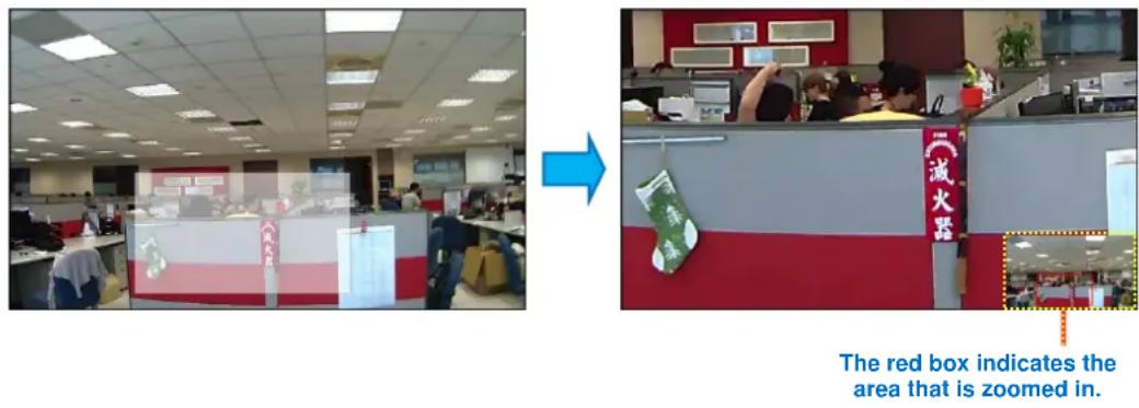
- Drag the red box over the image to pan and tilt the view in that direction.
Taking Snapshots
To take snapshots from the live video stream, perform the following:
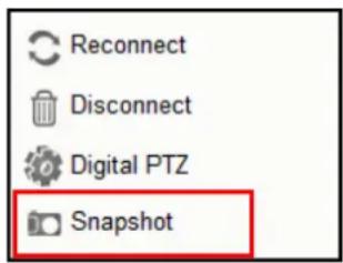
- Right-click on the channel window of the camera, and click Snapshot. The snapshot is saved on the clipboard.
- Open a graphics utility software (i.e. Paint).
- Press [Ctrl] + V to paste the snapshot.
- Save the snapshot as a new file.
Using the PTZ Control Panel
Use the PTZ Control Panel to pan, tilt, and zoom the camera. To display the PTZ Control Panel, click ☐ from the left panel menu.
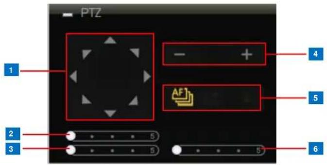
TIP: Move the mouse over the icon to display the function name.
NOTE: For non-PTZ/zoom cameras, PTZ functions are done using digital PTZ.
| Item | Description | |
| 1 | Pan / TiltControls | Click the arrows to pan / tilt the camera according to the configured speed on the sliders. |
| 2 | Pan Speed | Drag the slider to adjust the pan speed; 1 (slowest) to 5 (fastest). |
| 3 | Tilt Speed | Drag the slider to adjust the tilt speed; 1 (slowest) to 5 (fastest). |
| 4 | Zoom Control | Click the icons to zoom in or zoom out the camera view. |
| 5 | Focus Mode | Click the icon to toggle between modes:Auto FocusManual Focus: When Manual Focus is selected, the Near Focus and Far Focus icons become enabled.Click one of the focus icons to adjust the focus manually; you may also need to adjust zoom (6) to achieve the best focus and viewing angle. |
| 6 | Zoom Speed | Drag the slider to adjust the zoom speed; 1 (slowest) to 5 (fastest). |
Viewing by Preset Point and Tour
NOTE: The Preset Point Panel is available only when PTZ and zoom cameras are selected. For other cameras, the Preset Point Panel appears blank.
PTZ and zoom cameras can have up to 32 preset points and 32 tours configured on ECD-1000. A preset point is a user-defined area on the image where the camera is directed at or zoomed in. A tour is a group of preset points that the camera cycles through at specific interval time. The Preset Point Panel on the Live View screen allows users to view preset points and start or stop tours. Preset points and tours must be configured first in the Camera Setup screen (see 3.6 Configuring the Cameras on page 100).
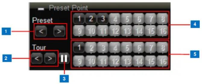
| Item | Description | |
| 1 | Preset PointBack / Next | Click < to view preset point 1 ~ 16 buttons or > to view preset point 17 ~ 32 buttons. |
| 2 | TourBack / Next | Click < to view tour 1 ~ 16 buttons or > to view tour 17 ~ 32 buttons. |
| 3 | Stop Tour | When the camera is on tour, click this icon to stop the tour. |
| 4 | Preset PointNumber | The numbers indicate the preset point number. If the button has a:Black background: The preset point is configured.Gray background: The preset point is not configured.Click a number button to display that preset point on the Live View screen. |
| 5 | Tour IDNumber | The numbers indicate the tour ID. If the button has a:Black background: The tour is configured.Gray background: The tour is not configured.Click a tour ID number to start the tour. |
Using the Toolbar
Click a menu and submenu option to use its function. The function is applied to all the cameras in the Live View.
Application Menu
- Video Title Bar: Click to hide or display the video title bar on top of every channel window. The bar contains the camera name and the system date and time.
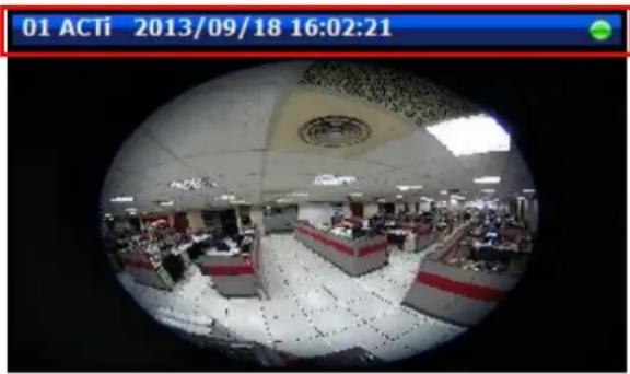
natural_image
Interior view of a busy trading floor with rows of desks and a large emblem on the ceiling (no readable text or symbols)- Stretch / Un-stretch Video: Select to stretch or un-stretch the video display.
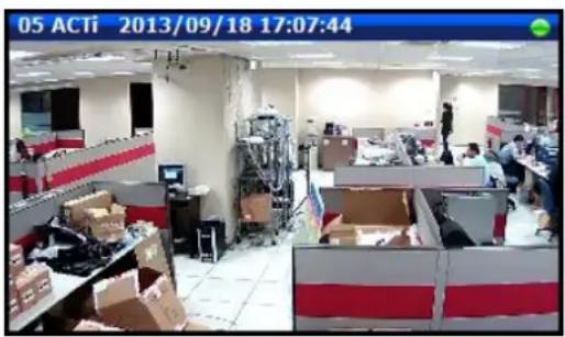
Stretched Video
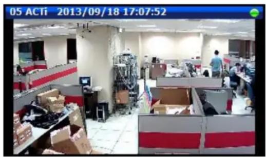
Un-stretched Video
- Disconnect All Channels: Select to disconnect all channels from the Live View display area. When disconnected, the Live View display area will be blank but the cameras will still be listed on the camera list panel.
- Decode I-frame / Auto Drop Frame: Select Decode I-frame to save computing power. With this function, ECD-1000 decodes only the I-frames, so the frame rate of each channel becomes 1 fps. This function is useful when using a computer which is also used for other applications.
When Decode I-frame is selected, the selection toggles to Auto Drop Frame.
By default, ECD-1000 is set to Auto Drop Frame. With this setting, ECD-1000 displays as many video frames as possible to achieve smooth video performance. However, this function uses more computing power. When the computer loading exceeds 80%, random channels start to decode I-frame for about 15 seconds, and then return to the original frame rate afterwards. This process continues until the computer loading drops under 80% or when the user switches to other layout or page.
- Logout: Click to logout from ECD-1000 but continue using Internet Explorer.
- Quit: Click to quit the entire session and close Internet Explorer.
Camera List Menu
The Camera List menu defines how the cameras are listed on the left panel.
- List: Click to list the cameras by channel ID and name only.
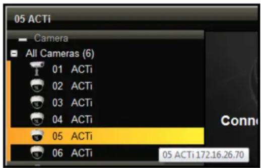
- Detail: Click to list the cameras with details such as IP address and camera model. When the mouse goes over to the camera list panel, the scroll bars appear to enable users to scroll through the camera details.
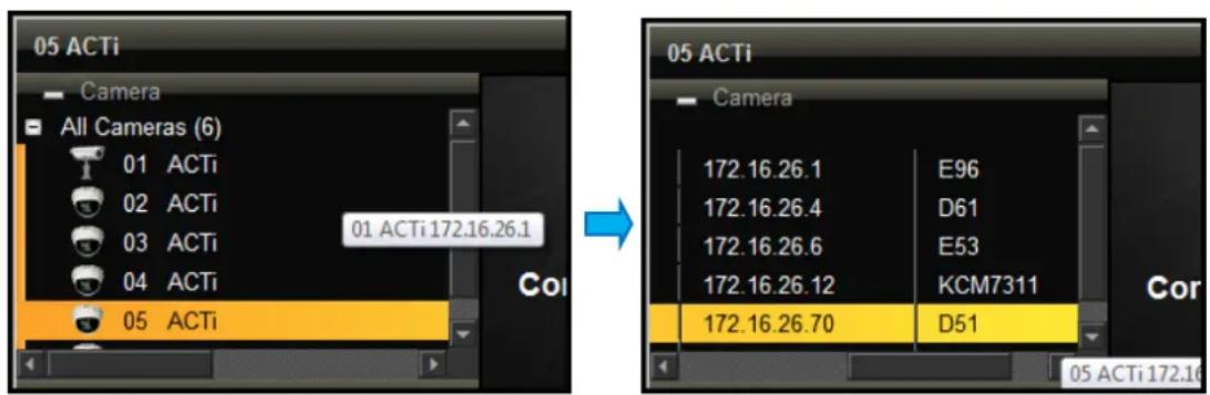
Hide Toolbar
Click Hide Toolbar to hide the toolbar from the Live View screen. Press the
Help
Click Help to access the website for more product information and documentation.
About
Click About to display the firmware version.
System Date and Time
Click the date and time to access the Date and Time setup page. See Date and Time on page 93.
3.3 The Setup Screen
Click the Setup tab to access the Setup screen.
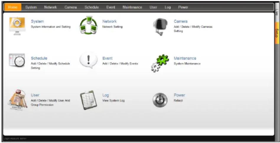
Click an icon from the Home menu or a page tab to access the menu page:
- System
- Network Menu
- Camera
- Schedule
- Event
- Maintenance
- User
- Log
- Power
3.4 Configuring the System Settings
System Information
On the Setup screen, click System.
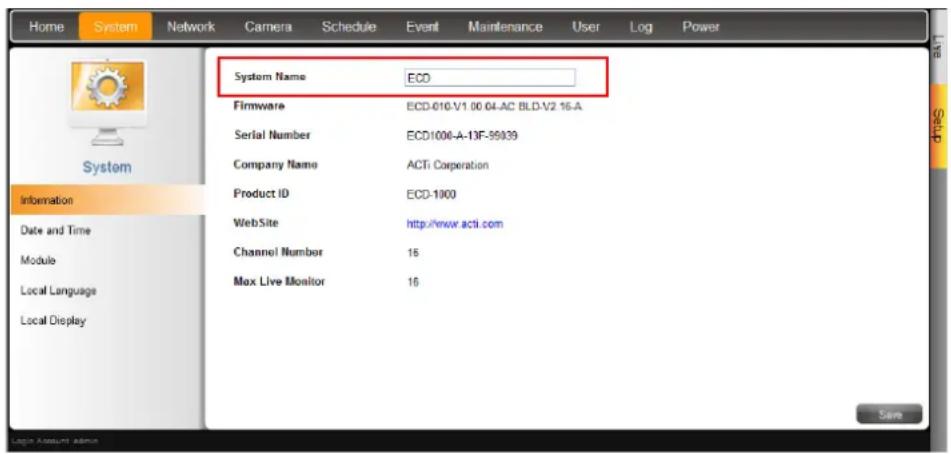
The system information is displayed.
- System Name: Name assigned to ECD-1000; can be modified. To modify the System Name, type the preferred name on the box. Click the Save button at the bottom of the screen to apply and save changes.
NOTE: The system name can be up to 10 alphanumeric characters, spaces and symbols are not allowed.
- Firmware: System firmware version.
- Serial Number: Product serial number.
- Company Name: Name of the manufacturer.
• Product ID: Product model name. - WebSite: Click the website to access the manufacturer website.
- Channel Number: Maximum number of supported cameras.
- Max Live Monitor: Maximum number of supported live channels.
Date and Time
The Date and Time page allows you to manually change the system date and time or sync with an NTP server.
Automatically Set the Date and Time
Select the time zone to automatically set the date and time.
- On the Setup screen, click System > Date and Time.
- On Time Zone, select the desired time zone. The system date and time automatically changes according to the current date and time of the time zone.
- If applicable, check the Daylight Saving box. Note that this box becomes enabled only if the Daylight saving time can be applied to the selected time zone.
Manually Change the Date and Time
- On the Setup screen, click System > Date and Time.
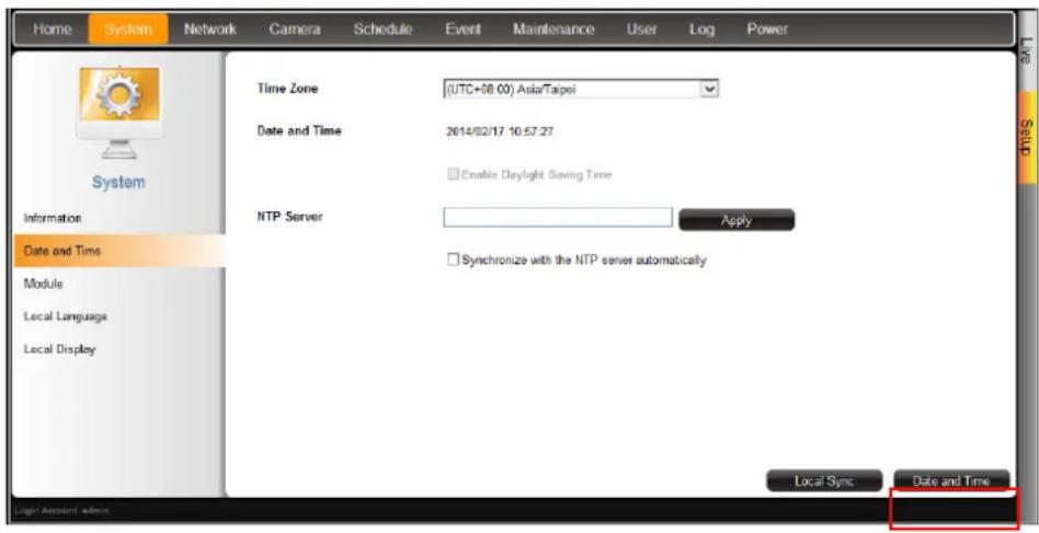
- Click the system date and time button.
3. Modify the date and time.
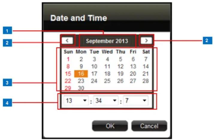
| Item | Description | |
| 1 | Month and Year | Select the month and year from the box. |
| 2 | Scroll Icons | Click to view the calendar of the previous or the next month. |
| 3 | Date | Click a date to set the date. Selected date is highlighted in orange, while the current date is in yellow. |
| 4 | Time | Select the hour, minute, and second from the corresponding boxes. |
4. When done, click OK to save.
Sync Date and Time with NTP Server
- On the Setup screen, click System > Date and Time.
- On NTP Server, type the URL address of the NTP server.
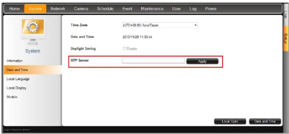
3. Click Apply. A message will appear to confirm if synchronization is successful.
NOTE: If the NTP Server is a domain name, make sure the IP setting and DNS setting of the system gateway are correct.
To delete NTP Server
To delete an NTP server, delete the URL address on the field and click Apply.
Module
The Module page allows users to select the maximum number of cameras that can be connected to ECD-1000. Options are: 4-channel, 9-channel, 12-channel, and 16-channel mode.
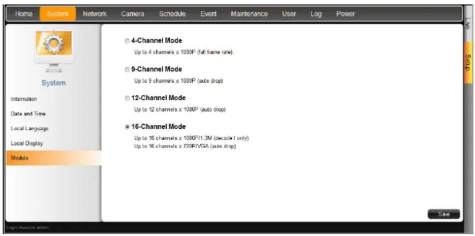
Language
To change the language of the local display interface, click System > Local Language on the Setup screen. Then, select the desired language from the box.
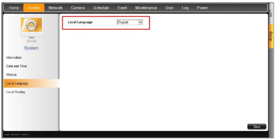
Local Display
The Local Display page allows users to show or hide information, such as the IP address, system date and time, or event trigger icons, on the Live View screen. By default, all options are enabled.
1. On the Setup screen, click System > Local Display.
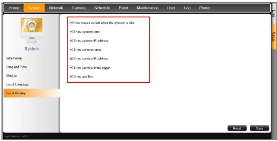
-
By default, all options are enabled. To disable a function, remove the check from its corresponding box.
-
Hide mouse cursor when the system is idle: If checked, the mouse cursor is hidden from the Local display if there is no mouse movement within 5 seconds.
- Show system time: If checked, the system date and time is displayed on the bottom of the Live View screen.
- Show system IP address: If checked, the system IP address is displayed on the bottom of the Live View screen.
- Show camera name: If checked, the camera name is displayed on the upper left corner of the channel.
- Show camera IP address: If checked, the camera IP address is displayed on the upper left corner of the channel. For security reasons, it is recommended to uncheck this function to hide the IP address from showing on the local display.
- Show camera event trigger: If checked, an event trigger icon, such as motion detection, will appear on the upper right corner of the channel when an event occurs.
-
Show grid line: If checked, the lines separating the camera channels are displayed on the Live View screen.
-
When modifications are done, click Save to apply and save the changes. Or, click Reset to re-check all the boxes back to its default.
3.5 Configuring the Network Settings
Viewing the Network Information
On the Setup screen, click Network.
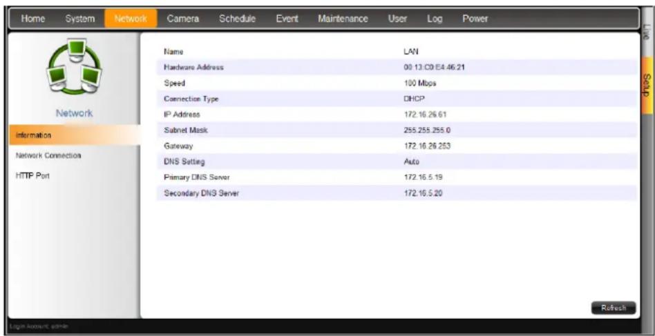
The network information, such as the Hardware Address (MAC address), Speed,
Connection Type, IP Address, Subnet Mask, Gateway, DNS Setting, and Primary and Secondary DNS Server are displayed.
To refresh the page, click Refresh.
Configuring the Network Connection
Use the Network Connection to configure the network settings of ECD-1000, which includes setting of the connection type and IP address.
There are two types of connection: Manual and DHCP.
- Manual: The IP address must be assigned manually, so are other network configurations like Subnet Mask, Gateway, etc. Note that the IP address must be unique for each device on the network. By default, ECD-1000 has a default IP of 192.168.0.200 and subnet mask of 255.255.255.0. Users may need to change the default IP and subnet mask to ensure ECD-1000 belongs to the same network segment as the cameras.
- DHCP Connection: On a DHCP network, the DHCP server assigns the IP address automatically. By default, ECD-1000 will automatically switch to DHCP connection mode and be assigned an IP address. However, if this does not happen, users need to manually change the Connection Type to DHCP. See Obtaining the IP Address Automatically on page 99.
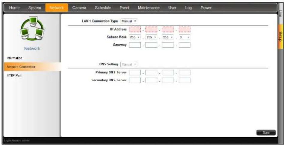
Setting the IP Address Manually
If your network does not have a DHCP server, perform the following to manually configure the network settings:
- On the Setup screen, click Network > Network Connection.
- On Connection Type, select Manual.
- Obtain the information from your network service provider and enter the IP Address, Subnet Mask, and other necessary settings.
NOTE: The IP Address and Subnet Mask must be filled in. Other settings may be left blank if not required by the network service.
- When done, click Save.
Obtaining the IP Address Automatically
If your network has a DHCP server, ECD-1000 will automatically be assigned an IP address. However, in case ECD-1000 does not detect the DHCP connection, perform the following procedures to obtain the IP address:
- On the Setup screen, click Network > Network Connection.
- On Connection Type, select DHCP.
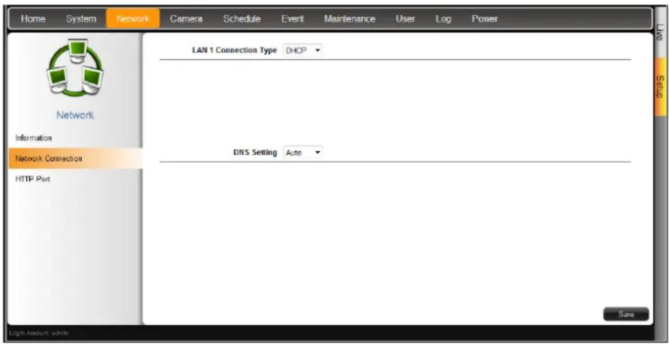
- Leave the default DNS Setting as "Auto".
- Click Save.
By default, ECD-1000 port number is 80. To change this value, click Network > Port Mapping on the Setup screen. Click Save to apply and save the changes.
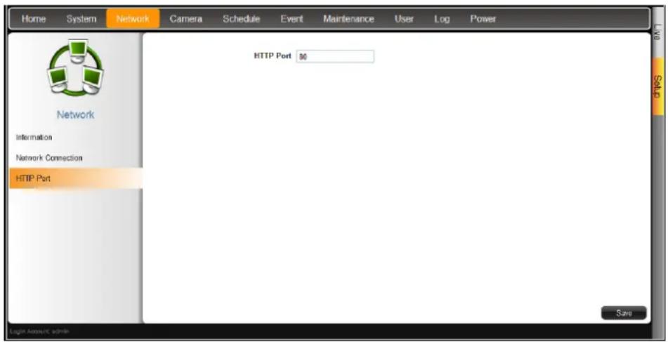
3.6 Configuring the Cameras
On the Setup screen, click Camera. The camera list table is displayed.
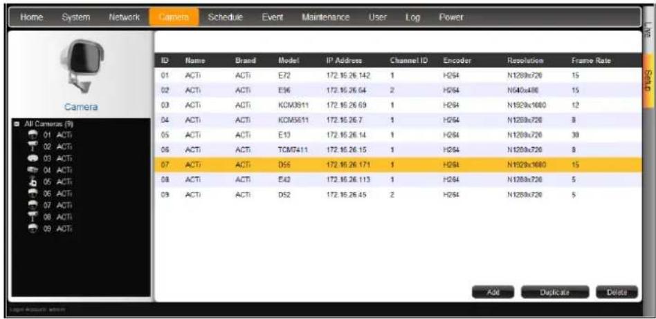
• To add cameras, click Add. See Adding Cameras on page 101.
• To add cameras with almost the same setting as an existing channel, see
• Duplicating Cameras on page 105.
• To delete cameras, see
- Deleting Cameras on page 110.
To access the camera properties, click a camera name from the camera list panel or double-click a camera from the table. The camera properties are displayed.
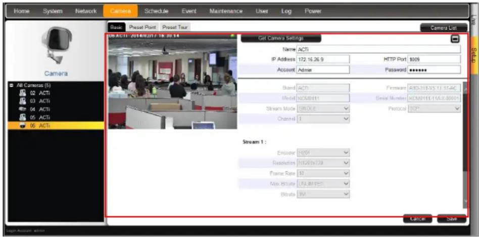
- To access the camera Web Configuration, click
- To view the camera list table, click Camera List.
- To view other cameras, click the camera from the camera list panel on the left.
- To configure preset points and tours of the camera, click the Preset Point or Preset Tour tab. These tabs appear only in PTZ and zoom cameras only. See Setting Preset Points on the Remote Client on page 111.

Adding Cameras
There are two ways to add cameras for viewing: by manually entering the IP address of the camera or by searching the cameras on the network.
NOTE: ECD-1000 supports third-party cameras. To validate specific camera models that can be integrated, visit our website (http://www.acti.com/3rdpartycamera).
Searching Cameras to Add
If you do not know the IP address of the camera or you want to add several cameras at the same time, you can search the cameras connected to the network and choose up to 9 cameras to connect to ECD-1000.
- On the Setup screen, click Camera.
- On the camera list table, click Add.
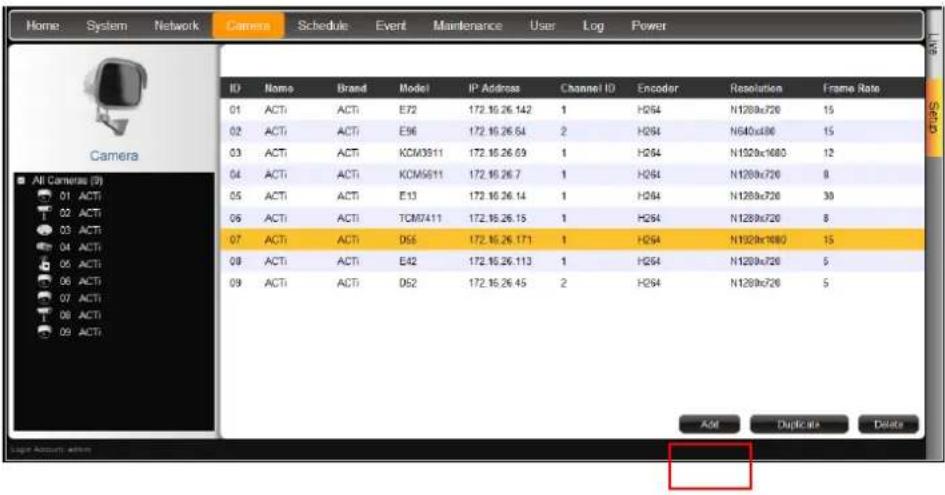
- Click Search Cameras.
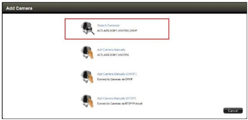
- The Search Cameras screen appears. The default Account "Admin" and Password "123456" are pre-entered. If the camera you want to add has different account and password, enter them on the Account and Password fields.
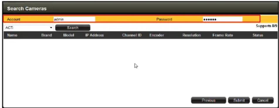
- Click Search. The cameras connected in the network are listed on the table.
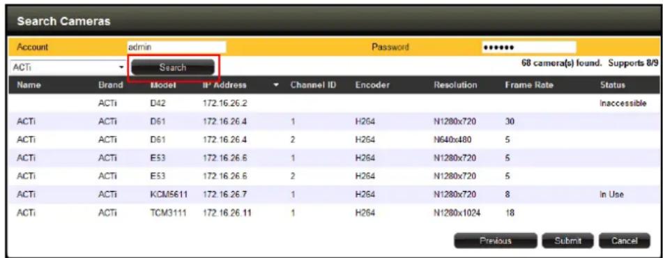
- Click one or more cameras to select it. The number of cameras that you can select depends on the channel mode selected in Module (see Module on page 95). Selected cameras are highlighted in orange.
NOTE: The Status column shows the status of the camera:
- Inaccessible: The camera account or password may be different from what you have entered on Account and Password fields. So that camera cannot be accessed.
-
In Use: The camera is already added to ECD-1000 for live viewing.
-
Click Submit to add the selected cameras to ECD-1000 for live viewing.
Adding Cameras Manually
To add cameras manually, you need to know the IP address, HTTP port, User Name and Password of the camera you want to connect to.
- On the Setup screen, click Camera.
- If the camera list table is not shown, click All Cameras or Camera List.
- On the camera list table, click Add.
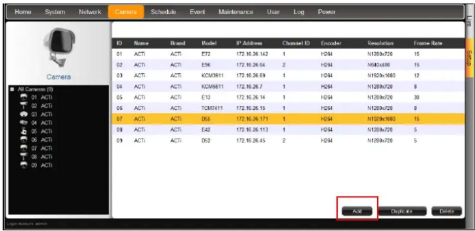
- Click Add Camera Manually or Add Camera Manually (ONVIF).
- Add Camera Manually
If your network does not have a DHCP server, perform this step to connect an ACTi camera.
- Add Camera Manually (ONVIF)
If the camera is a 3^rd -party camera which is ONVIF-compliant, you can manually add it with this method.
- Add Camera Manually (RTSP)
In case you want to add cameras via Real Time Streaming Protocol (RTSP), use this function. This feature is useful when adding third party cameras which support the standard RTSP.
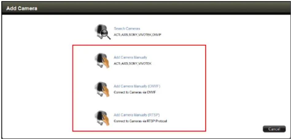
- Type a name you want to use to identify the camera (maximum of 32 alphanumeric characters, no spaces nor symbols). This name is saved only on ECD-1000 and does not affect the settings on the camera side.
- Enter the IP Address, HTTP Port, User Name and Password of the camera you want to connect to. For adding cameras via RTSP protocol, you need to give the URI (Uniform Resource Identifier)A and RTSP Port (by default 554), If you do not know the URI of the camera, click to select from the most common manufacturers on the list. Once a manufacturer is selected, its URI is filled up on the field. If the predefined URI does not work, check the camera specifications for details.
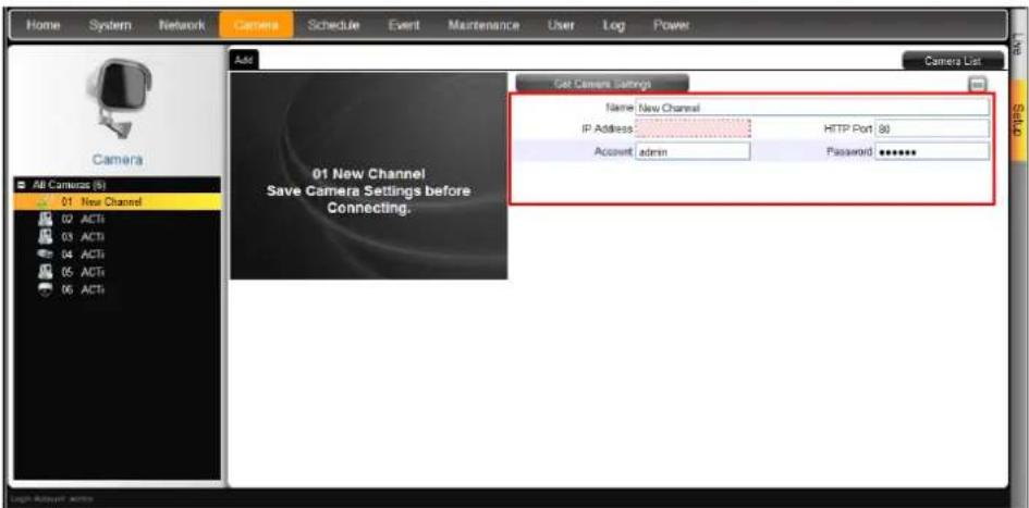
- Click Get Camera Settings. ECD-1000 connects and retrieves the camera settings. The camera streaming properties are shown on the page however the video display is still empty at this point.
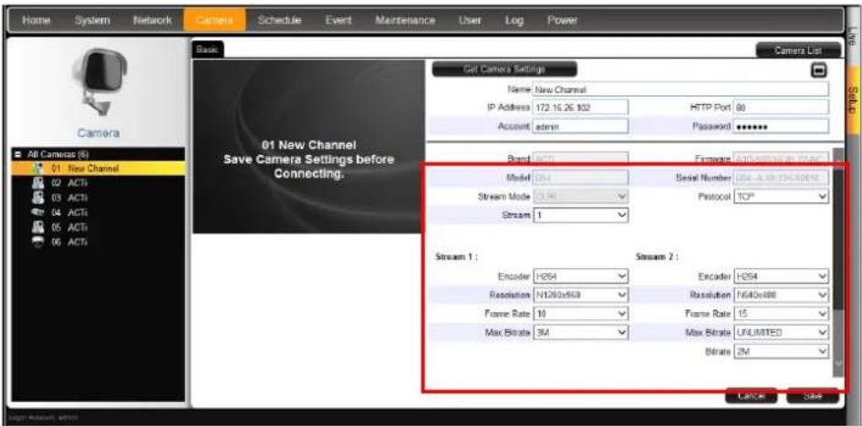
- Click Save. The live video appears on the display window.
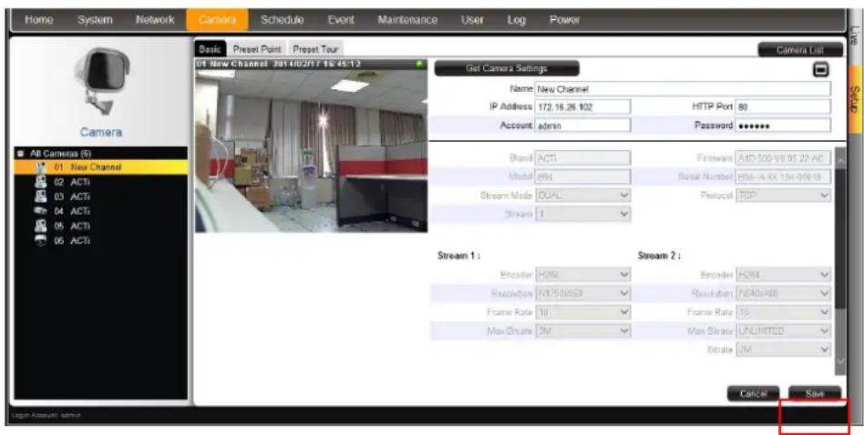
Duplicating Cameras
Use this function to add another camera with almost the same camera settings as the selected camera. So instead of entering all the information one by one, duplicate the camera settings first and then modify afterwards. However, to use this function, there must be at least one available channel without a connected camera.
- Select the camera you want to duplicate from the table, and then click Duplicate.
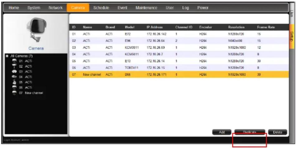
- A confirmation message appears. Click OK to continue.
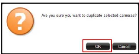
- The copied camera is automatically added to the next available channel. Double-click the camera from the table to access the camera properties and modify the settings.
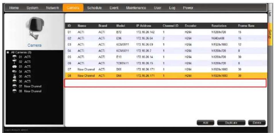
Modifying Camera Settings
In some cases, you may need to modify the camera connection and streaming properties. To do this, follow the procedures below:
- On the Setup screen, click Camera.
- Select the camera from the camera list panel.
- Click Get Camera Settings.
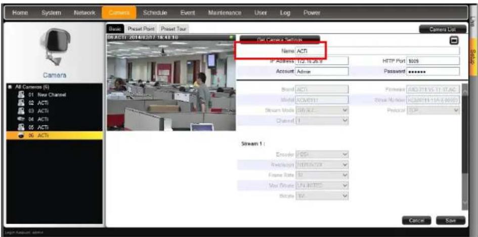
- Modify the camera connection and streaming properties, as needed. Other properties can only be modified on the camera configuration webpage, in this case, click ☐ access Web Configurator.
| Item | Description |
| Name | Enter a descriptive name to assign to ECD-1000, e.g. location of camera, etc. This name is not saved or shown on the camera side. The maximum length is 32 alphanumeric characters, symbols and spaces are not allowed. |
| IP Address | Enter the camera IP address. |
| HTTP Port | Enter the HTTP port. Default port is 80. |
| User Name | Enter the user name to log in to the camera. Default is “admin”. |
| Password | Enter the password to log in to the camera. Default is “123456”. |
| Brand | Displays the camera manufacturer name. This field cannot be modified. |
| Firmware | Displays the camera firmware version. This field cannot be modified. |
| Model | Displays the camera model. This field cannot be modified. |
| Serial Number | Displays the camera serial number. This field cannot be modified. |
| Stream Mode | Displays whether the camera has Single or Dual stream mode.This field cannot be modified. |
| Protocol | Displays the video stream protocol. You can modify the video stream protocol, as needed. |
| Channel ID | For dual stream cameras, select the stream to view. Usually, stream 1 or Channel ID 1 is configured to be the best quality stream for recording purposes and stream 2 or Channel ID 2 with basic quality for live viewing, like viewing through ECD-1000. Once the Channel ID is selected, the succeeding camera properties, such as encoder, resolution, etc., change according to the compression settings of the selected stream. |
| Encoder | Displays the video stream encoder type. You can modify the encoder type for the current stream, as needed. Note that for local viewing, only H.264 is supported. |
| Resolution | Displays the video stream resolution. You can modify the resolution, as needed. Note that for local viewing, only up to 2 megapixel (1920 x 1080) is supported. |
| Frame Rate | This is the amount of frame per second of the video stream. You can modify the frame rate, as needed. |
| Bitrate Mode | Under “Constant Bit Rate” mode (CBR), the camera keeps the stable bitrate regardless of the complexity of the scene. Under this mode, the video quality may vary if the bit rate value is set too low. It is easier to do storage and network bandwidth consumption estimations under this mode compared to Variable Bit Rate mode.Under “Variable Bit Rate” mode (VBR), the camera will keep the video quality stable while the bit rate may occasionally go up or down, depending on the complexity of the scene. |
| Max Bitrate(only for H.264) | The bitrate will be floating slightly under that limit. For example, if the limit is set as 2M, the bitrate will be floating around 1.6~2.0 Mbps. If the Max Bitrate is “Unlimited”, then the Bitrate selection box will appear that defines the bit rate level. |
| Bitrate(only for H.264) | When Max Bitrate is “Unlimited”, the user can define the AVERAGE bit rate. For example, if the Bitrate is 2M, then occasionally, the actual bit rate may go below or beyond 2M, but in the long run, the average bit rate will be very close to 2M. This mode allows the most accurate storage estimations, however,while planning the bandwidth, please consider the occasional peaks of bit rate. |
| Video Quality(only for MJPEG) | The user can define the quality with the numeric scale from 1 to 100. The default MJPEG quality is 60. The higher is the quality level, the more bit rate the camera will use to achieve the target quality. However, note that local Live View cannot display streams other than H.264. |
| Quality(only for H.264) | Under VBR mode, the bit rate will be floating while the video quality will be stable and follows the quality standard set by the user. The user can choose either “High”, “Medium” or “Low” quality. The higher is the quality level, the more bit rate the camera will use to achieve the target quality. |
| GOP 1 I-Frame | Under VBR mode it is possible to adjust the GOP length - that is the occurrence rate of I-frames. By default, there is one I-frame per second. For example, in case of 30fps, there will be 1 I-frame and 29 P-frames every second by default. When the GOP is changed to “1 I-frame per 5 seconds”, then there will be one I-frame, followed by 149 P-frames. In case of the static scenes, long GOP can further minimize the bandwidth and storage consumption. |
| Mounting Type(only for Fisheye cameras) | Displays the mounting type of the camera. This field appears only on Fisheye camera models and cannot be modified. |
| Installation Angle(only for Fisheye cameras) | Displays the installation angle of the camera. This field appears only on applicable Fisheye camera models and cannot be modified. |
- When done, click Save. The camera properties are saved and ECD-1000 restarts the connection.
Deleting Cameras
- On the Setup screen, click Camera.
- If the camera list table is not shown, click All Cameras or Camera List.
- On the camera list table, click the camera(s) to delete. Click as many cameras as needed.
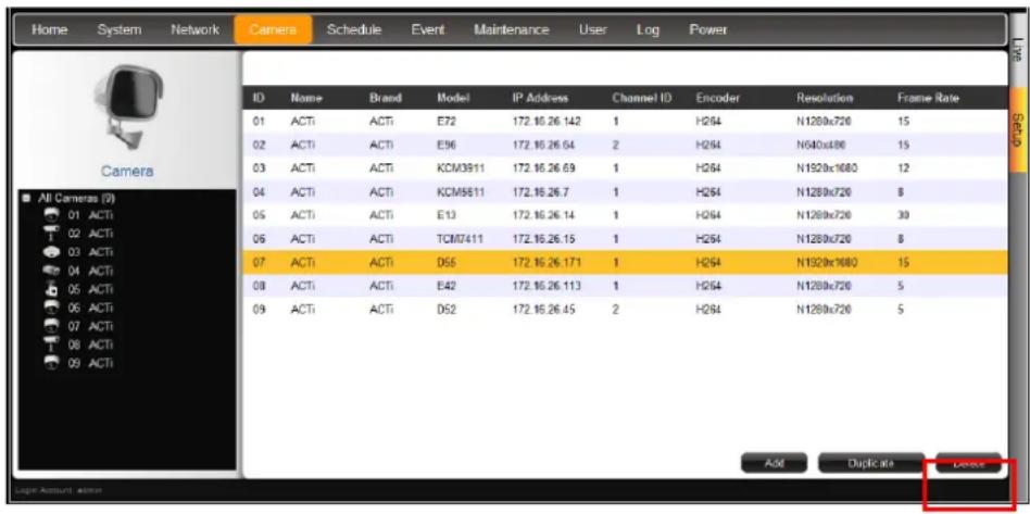
- Click Delete.
- A message appears, click OK to confirm.
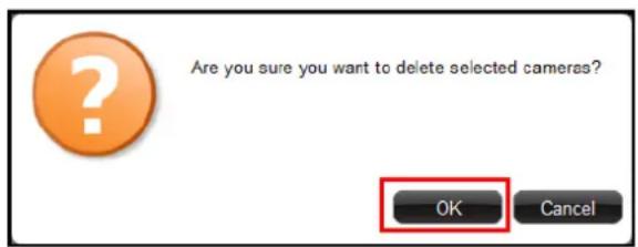
Setting Preset Points on the Remote Client
A preset point is a user-defined area where the camera is directed at or zoomed in. Up to 32 preset points can be configured on ECD-1000. When preset points are created on ECD-1000, they are automatically synced on the camera side, and vice versa.
How to Create / Modify Preset Points
- On the Setup screen, click Camera.
- Select the camera from the left panel menu, then click the Preset Point tab. A red cross-hair appears on the display window.
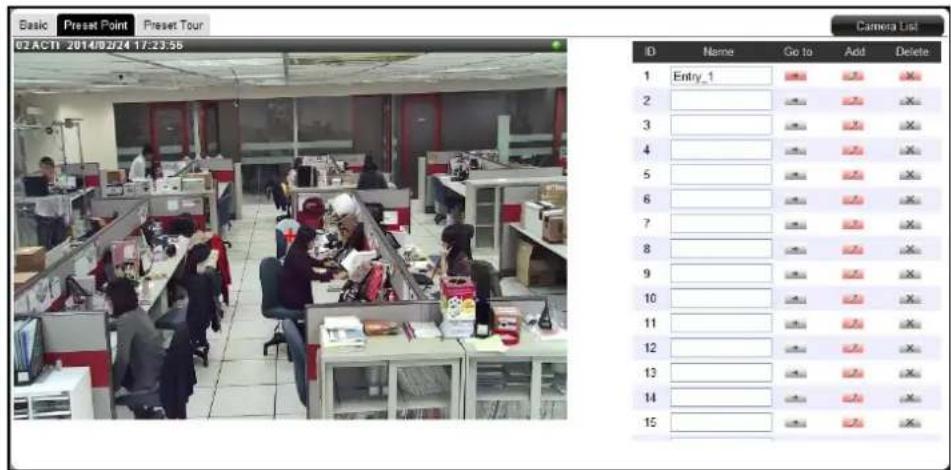
-
Pan, tilt and zoom the camera to the desired area:
-
To pan and tilt, click the mouse on the display window to move the direction of the camera (available on PTZ cameras only).
• To zoom in or zoom out the image, scroll the mouse wheel up or down. -
Click the Add 📋 icon of a preset point. A default name is given to the preset point; retain or modify the name, as preferred.
TIP: Click the corresponding Go to → icon to go to a preset point
How to Delete Preset Points
On the Preset Point page tab of the selected camera, click the corresponding
Delete icon of the preset point to delete. The name becomes blank to indicate the preset point has been deleted
Setting Preset Tours on the Remote Client
Several preset points can be grouped into a "Tour" which directs the camera to cycle through the series of preset points at specific interval time. Up to 32 tours can be set on ECD-1000. The tour configuration is saved only on ECD-1000, not on the camera side.
How to Create / Modify Tours
To create tours, make sure one or more preset points have already been created. The tour configuration on ECD-1000 is not synced with the tour configuration on the camera side.
- On the Setup screen, click Camera.
- Before creating a tour, the preset points must be created first (see Setting Preset Points on the Remote Client on page 111).
- Click the Preset Tour tab.
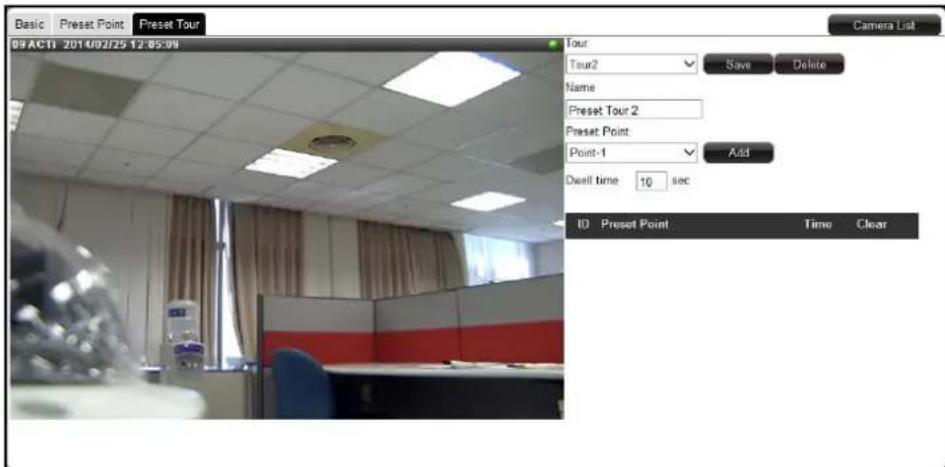
- On Tour, select the tour ID from the list. A default name is given to the tour; retain or modify Name, as preferred.
- On Preset Point, select the preset point to include on the tour and specify the Dwell time (in seconds). Dwell time is the amount of time that the camera will remain in the preset point.
-
Click Add. The preset point is added to the list.
-
Repeat steps 5 \~ 6 to add more preset points.
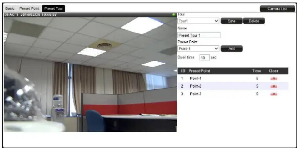
TIP: To change the order of preset point sequence, drag a preset point up or down the list.
- When done, click Save.
How to Delete Tours
On the Preset Tour page tab of the selected camera, click the corresponding
Delete ✗ icon of the preset point to delete. The name becomes blank to indicate the preset point has been deleted
3.7 Configuring User Access
User access permissions are managed by Groups. Groups define what functions and devices are allowed for each user. Different Groups may have different access rights, like Live View, Setup Access, and Remote Access.
To setup access permissions, perform the following:
- Create a group. See below.
- Add users to the group. See Adding Users on page 116.
- Set the access rights. See Granting Access Permission on page 117.
Creating Groups
By default, an Administrator group with the "admin" user is preset with Live View, Setup Access and Remote Access rights.
- On the Setup screen, click User > Group.
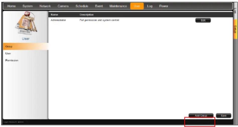
-
Click Add Group.
-
Enter the group Name (up to 32 characters) and Description (up to 128 characters).
NOTE: The group name can be up to 32 alphanumeric characters; symbols and spaces are not allowed.
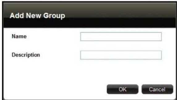
- Click OK. The new group appears on the group table.
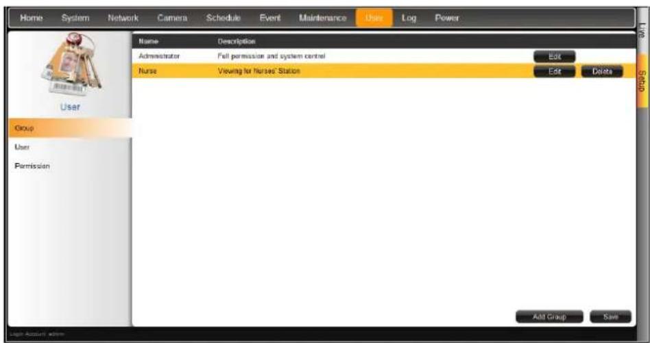
Adding Users
- On the Setup screen, click User >User. By default, the "admin" user is preset and cannot be deleted.
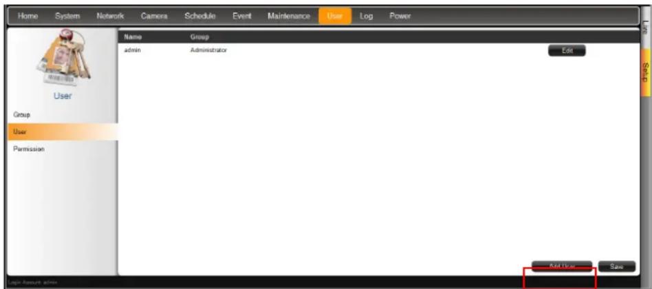
- Click Add User.
- Enter the following information:
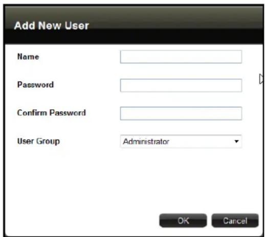
| Item | Description |
| Name | Enter a user name. The name can be up to 63 alphanumeric characters; symbols are not allowed. |
| Password | Enter the password that will be used by the user to log into ECD-1000. |
| Confirm Password | Re-type the password here. The two passwords must match. |
| User Group | Select the group to where the user belongs. This group defines the access rights granted for the user. |
- Click OK. The new user is added to the user table.
Granting Access Permission
- On the Setup screen, click User > Permission.
- On Group, select the group.
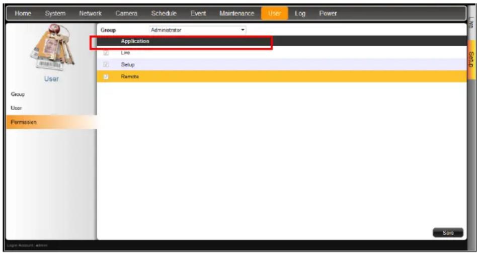
- Check the box to grant its access permission, options are:
• Live: Permission for Live View. Live View access is always enabled.
- Setup: Permission to access the Setup screen from both the local and remote client. Granting this access enables the user to modify the camera and system settings.
- Remote: Permission to access ECD-1000 through a remote client computer.
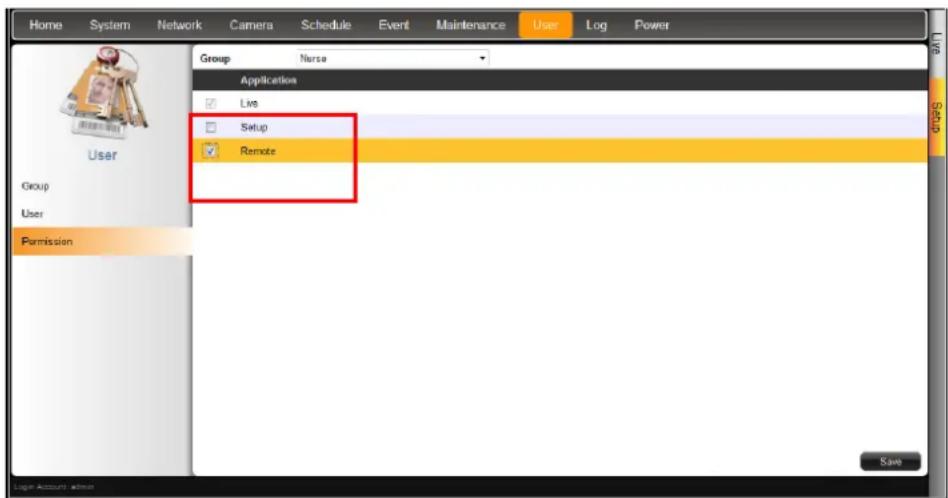
- When done, click Save.
Managing Groups and Users
Except for the Administrator group, all user-defined groups and users can be modified.
- To modify a group or user, click the corresponding Edit button.
- To delete a group or user, click the corresponding Delete button.
3.8 Managing Network Loss
When a camera suddenly disconnects from the network, ECD-1000 will trigger a network loss notification by displaying a network loss icon and a beep sound.
By default, the trigger is enabled for 24 hours a day and 7 days a week. However, the beep sound must be enabled and configured separately.
Scheduling Network Loss Trigger
- On the Setup screen, click Schedule.
- Select the camera from the camera list panel.
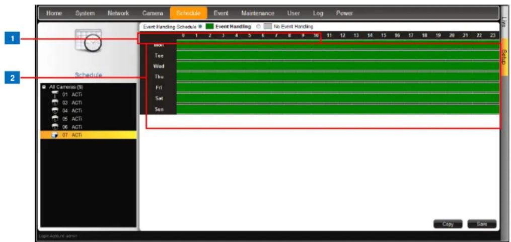
| Item | Description | |
| 1 | Event HandlingSchedule | • Event Handling: Enables event trigger.• No Event Handling: Disables event trigger. |
| 2 | Time Table | Shows green cell if event trigger is enabled and gray cell if event trigger is disabled. |
-
Select either Event Handling or No Event Handling.
-
Drag the mouse over the time table to select the time period. By default, the schedule affects all the days of the week.
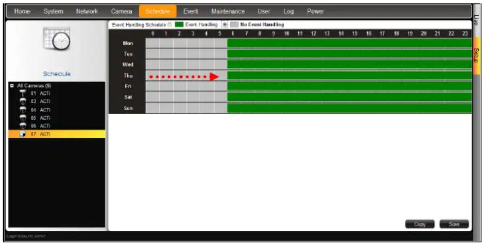
- To exempt a particular day from time selection, click the day. A lock icon appears. In the example below, Saturday and Sunday are locked so both days are not included in the time selection.
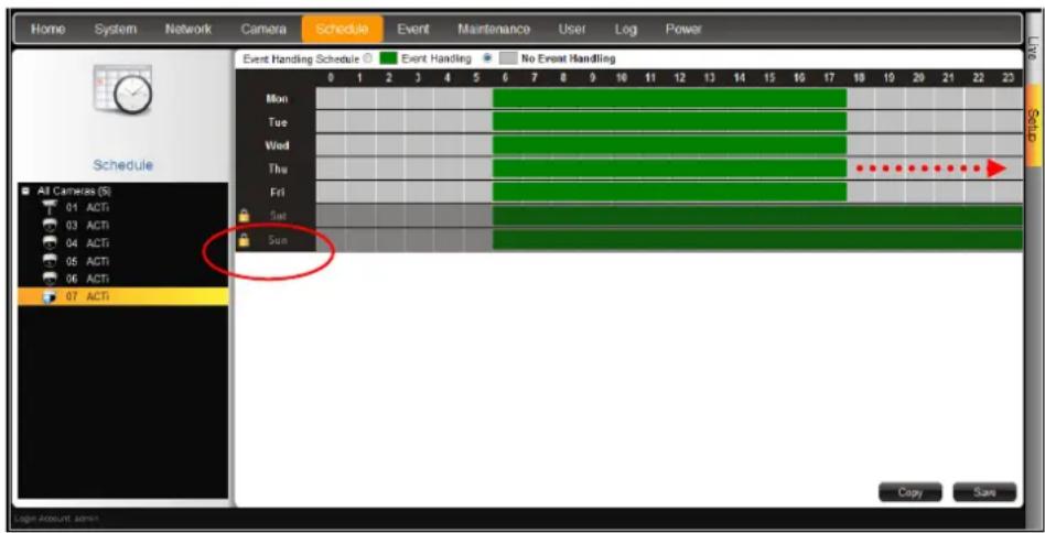
- When done, click Save.
TIP: Instead of manually modifying the event trigger on all cameras, users can copy the schedule to other channels. See Copying Event Schedule Settings on page 122.
Enabling Beep Sound Trigger
To enable the beep sound when a camera or video server is disconnected from the network, do the following:
-
On the Setup screen, click Event.
-
Click on Network Loss or Video Loss.
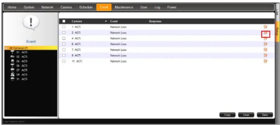
- Check Beep to enable the beep sound.
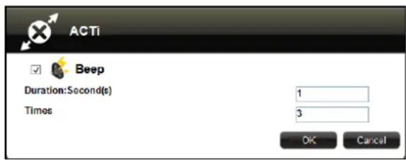
- Set the beep duration and the number of beeps to sound when the event is triggered.
- Click OK.
- Click Save to save the configurations.
Deleting Beep Trigger
Check the box of the camera and then click Clear to delete the event trigger. More than one camera can be selected at one time.
Copying Event Schedule Settings
Instead of manually modifying the event schedule and beep settings on all cameras one by one, users can copy the settings to other channels.
- After setting the event schedule or beep settings, click Copy. The Copy Schedule window appears.
- The current camera is highlighted in orange. Click the Copy From button. This sets the current camera as the source.
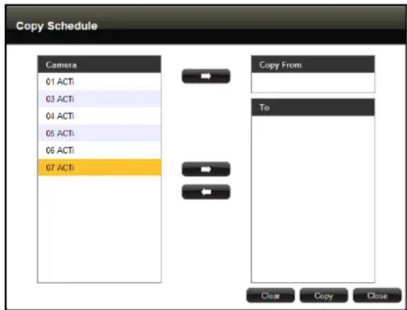
- Select camera(s) from the left panel and click the To button.
- Click Copy. The current camera event schedule or beep settings will be copied to the camera(s) under To.
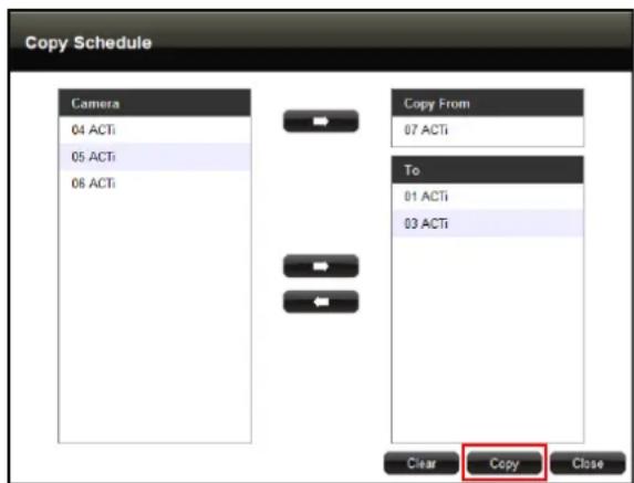
- A message appears when copy is complete. Click OK to close the window.
3.9 System Maintenance
The Maintenance page allows users to upgrade the firmware, backup or restore the system settings, and save error reports for troubleshooting.
Upgrading the Firmware
- Check and download the latest firmware package from the website (www.acti.com).
- On the Setup screen, click Maintenance > Firmware Upgrade.
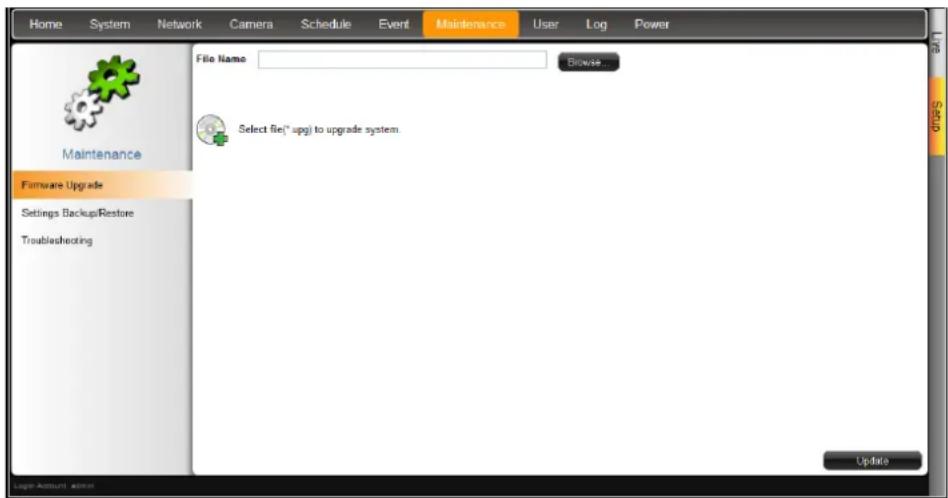
- Click Browse, and then browse for the downloaded firmware file (*.upg).
- Click Update to start the upgrade.
WARNING: Do not restart or turn off the remote computer while the system is upgrading the firmware!
- A message appears when upgrade is complete, click OK to reboot ECD-1000.
NOTE: All video streams will be lost for a few seconds until ECD-1000 completes the reboot process.
Saving Backup Settings
It is recommended to make regular system backup in case of unexpected disasters or accidents.
- On the Setup screen, click Maintenance > Settings Backup/Restore.
- Click Backup.
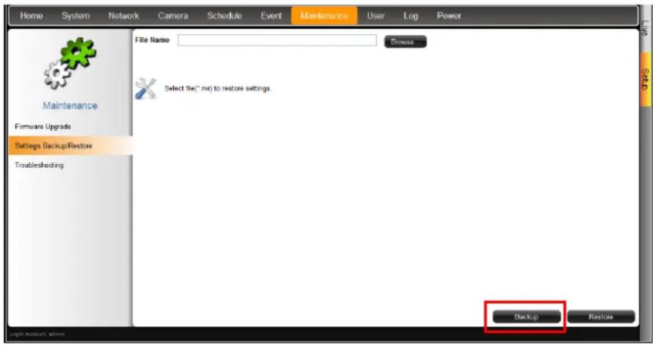
- A pop up message appears. ECD-1000 creates a backup file of the whole system settings as Backup_[yyyymmdd].nvr file. Save the file to the hard disk or to a USB disk connected to the remote computer.

The backed up settings include the following properties: (1) System Settings including System Name, Date & Time, Network, and Mouse, (2) Camera Settings, (3) Schedule Settings, and (4) Event Management.
Restoring Backed Up Settings
- On the Setup screen, click Maintenance > Settings Backup/Restore.
- Click Browse. Then browse for the backed up file (Backup_[yyyymmdd].nvr).
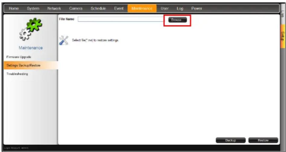
- Click Restore.
- A confirmation message appears, click OK to continue.
- When done, click OK to restart the system for the changes to take effect.
Troubleshooting
The Troubleshooting page allows users to export an error report (*.tgz) to be sent to the Customer's Help Desk (CHD) for troubleshooting purposes.
- On the Setup screen, click Maintenance > Troubleshooting.
- Click Export.
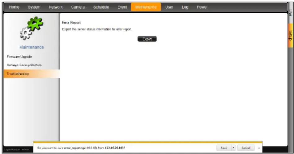
An error report (error_report.tgz) is generated. Save the file and send it to the CHD for troubleshooting.
3.10 Managing the System Log
The Log page allows users to view ECD-1000 activity log and save a log report as an XML file. ECD-1000 saves the latest 3000 logs. Logs can be filtered according to date and the source of activity.
- On the Setup screen, click Log.
- To filter according to date, select All Days to display all the logs or select Date Range and click the date to change the date.
-
To filter by source of activity, check or uncheck the filter under Log Type. Or, select the options under Other Conditions for more filtering options.
-
Click Search to start the search.
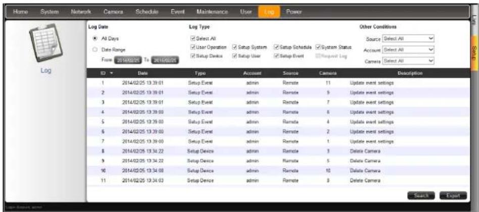
- To save the log report, click Export.
- Browse for the target location and save the log report file (*.xml).
- When log export is complete, click OK.
- To refresh the list, click Refresh.
3.11 Rebooting the Device
- On the Setup screen, click Power.
- Click Reboot.
- When the confirmation message appears, click OK to reboot.
NOTE: All video streams will be lost for a few seconds until ECD-1000 completes the reboot process.
Chapter 4: Installation and Maintenance
This chapter describes the different ways to install ECD-1000:
- Surface Mount
- VESA Mount
- Pole Mount
4.1 How to Surface Mount?
ECD-1000 can be mounted on a straight wall or on a table or pedestal. For wall installation, it is recommended to install ECD-1000 with the HDMI and Composite connectors facing down.
- Mark the 4 screw holes on the surface.
- If necessary, drill the holes and insert the plastic plugs.
- Attach the 4 supplied screws to secure the device.
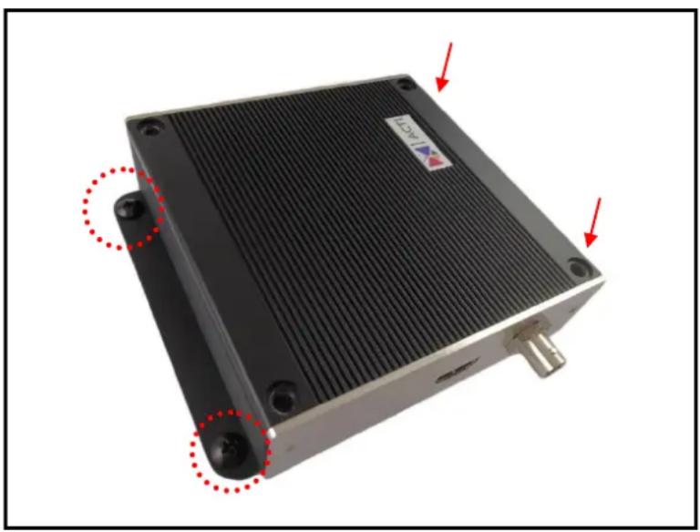
natural_image
Exterior view of a black industrial heat exchanger or cooling unit with red arrows pointing to mounting points (no text or symbols visible)4.2 How to Use VESA Mount?
ECD-1000 is designed to be directly installed between a VESA mount and a monitor.
- Place the device in between a VESA mount (10 x 10) and the monitor, with the top side of the device facing the monitor while the bottom side facing the VESA mount.
- Attach the 4 supplied long screws to secure ECD-1000.
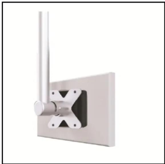
natural_image
3D rendering of a metallic vertical rod mounted on a rectangular base with mounting flanges (no text or symbols visible)4.3 How to Use the Pole Mount?
ECD-1000 comes bundled with pole mount accessories, like the cable straps and the bracket. The cable straps can hold poles with 1" to 2" diameter.
- With the smooth side outwards, insert the supplied cable straps through the holes

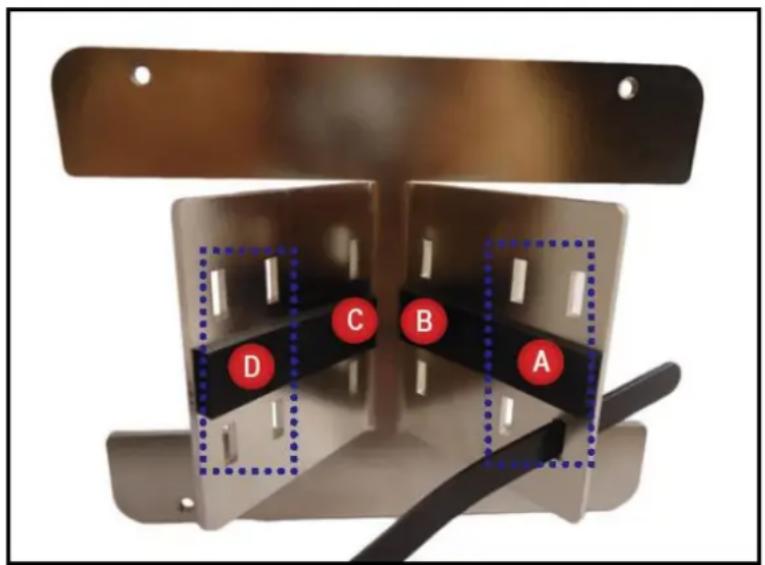
NOTE: Use the inner A and D holes if mounting on a pole with 1" diameter or the outer A and D holes for a 2" diameter pole.
- Align the pole mount to the pole.
- Insert the cables through the latches and push all the way until they fit snugly to the pole.
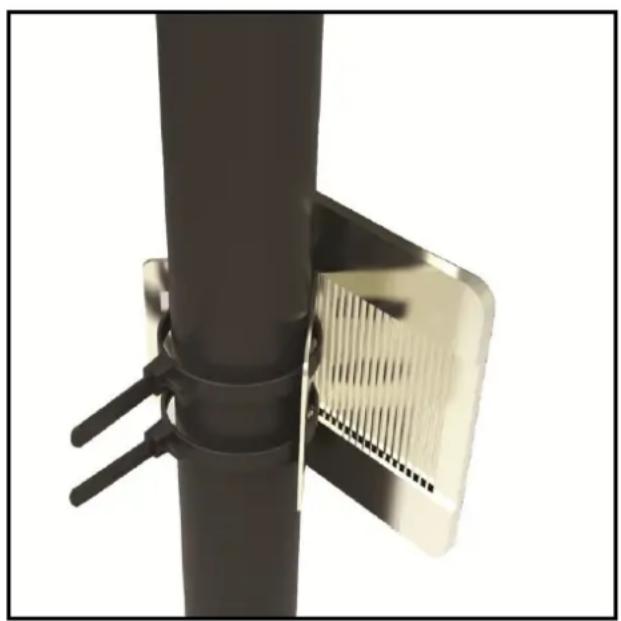
natural_image
Close-up of a black vertical pole with two metal grilles attached, no visible text or symbols- Align ECD-1000 to the mount with the Ethernet port side up and HDMI port side down.
- Attach the 4 supplied long screws to secure ECD-1000 to the mount.
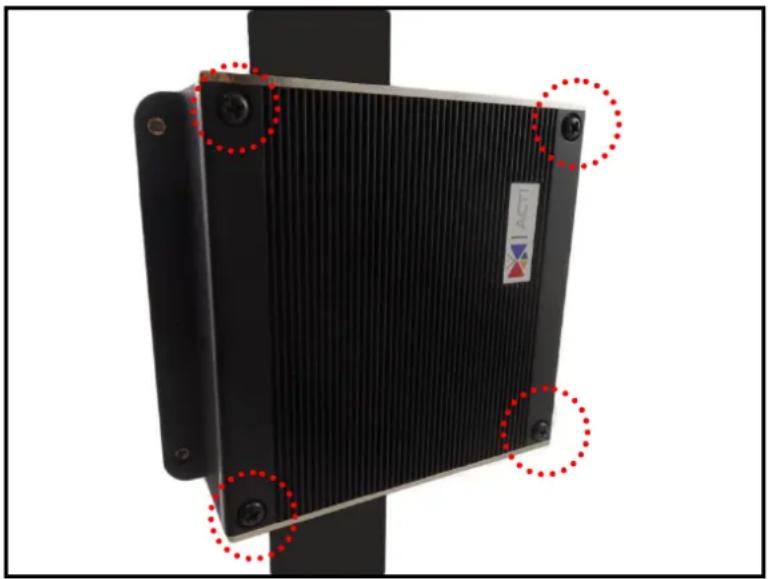
natural_image
Close-up of a black industrial heat exchanger or cooling unit with red dotted circular annotations and a small logo on the cover (no readable text or symbols)
ACTi
Connecting Vision
Copyright © 2014, ACTi Corporation All Rights Reserved
7F, No. 1, Alley 20, Lane 407, Sec. 2, Ti-Ding Blvd., Neihu District, Taipei, Taiwan 114, R.O.C.
TEL: +886-2-2656-2588 FAX: +886-2-2656-2599
Email: sales@acti.com

- ECD-1000
- User Manual
- Legal Notice
- Disclaimer
- Copyright
- Trademarks
- Regulatory Compliance Information
- Federal Communications Commission Statement
- European Community Compliance Statement
- About This Manual
- Target Audience
- Technical Support
- Table of Contents
- Chapter 1: Hardware Overview ...... 10
- Introduction ...... 11
- Connecting Devices 15
- Accessing ECD-1000.... 19
- Device Maintenance.... 20
- Chapter 2: Local Management ...... 21
- Accessing for the First Time 22
- The Live View Screen.... 27
- The Login Screen 33
- Using the PTZ Control Panel 35
- Accessing the Setup Screen 42
- Configuring System Settings.... 43
- Configuring Network Settings...... 49
- Configuring the Cameras....52
- Managing Network Loss Event 65
- Rebooting the Device....69
- Chapter 3: Remote Management....70
- Accessing ECD-1000 Remotely 71
- The Live View Page 78
- The Setup Screen....91
- Configuring the System Settings 92
- Configuring the Network Settings 97
- Configuring the Cameras.... 100
- Configuring User Access.... 114
- Managing Network Loss 119
- System Maintenance 123
- Managing the System Log 127
- Rebooting the Device.... 127
- Chapter 4: Installation and Maintenance ...... 128
- Chapter 1: Hardware Overview
- Introduction
- Package Contents
- Device Overview
- System Requirements
- Supported Video Format
- Decoding Limitation
- Connecting Devices
- Connection Architecture
- Preparing the Power Adaptor
- Connecting to Local Display
- Local Display via HDMI Connection
- Local Display via Composite Connection
- Connecting the Cameras
- Accessing ECD-1000
- Local Access
- Remote Access
- Local vs. Remote Access
- Device Maintenance
- Resetting the Device
- Switching Between NTSC and PAL Mode
- Chapter 2: Local Management
- Accessing for the First Time
- Quick Setup
- Step 1: Login
- Step 2: Change the IP Address (If necessary)
- Change the IP Address on Network without DHCP Server
- Step 3: Add Cameras
- The Live View Screen
- The Menu Panel
- Changing the Layout
- Viewing Channels in Full Screen
- Viewing Channels by Patrol
- Repositioning Channels
- The Login Screen
- Using the On-Screen Keyboard
- Using the PTZ Control Panel
- NOTE:
- Setting Preset Points
- How to Create / Modify Preset Points
- How to Delete Preset Points
- Setting Tours
- How to Create / Modify Tours
- How to Delete Tours
- Accessing the Setup Screen
- The Setup Screen
- Configuring System Settings
- System Information
- Module
- Date and Time
- Automatically Set the Date and Time
- Manually Change the Date and Time
- Sync Date and Time with NTP Server
- To delete NTP Server
- Language
- Mouse
- Local Display
- Local Audio Out
- Configuring Network Settings
- Viewing the Network Information
- Configuring the Network Connection
- Setting the IP Address Manually
- Obtaining the IP Address Automatically
- Configuring the Cameras
- The Camera Setup Page
- Adding Cameras
- Searching Cameras to Add
- Adding Cameras Manually
- Adding ONVIF-Compliant Cameras Manually
- Adding Cameras Manually via RTSP
- Click Save.
- Duplicating Cameras
- Modifying Camera Settings
- Reconnecting Cameras
- Deleting Cameras
- Managing Network Loss Event
- Scheduling Network / Video Loss Trigger
- Enabling Beep Sound Trigger
- Copying Event Schedule Settings
- Rebooting the Device
- Chapter 3: Remote Management
- Accessing ECD-1000 Remotely
- How to Access ECD-1000?
- Accessing From a Network with DHCP Server
- Accessing From a Network without DHCP Server
- The Login Screen
- The Setup Wizard
- Click Next.
- The Live View Page
- Viewing the Cameras
- Zooming In
- Changing the Window Layout
- Patrolling Channels
- Syncing Remote and Local Live View Display
- Reconnecting the Cameras
- Removing Video Stream from Live View
- Using Optical / Digital PTZ
- How to Use Optical PTZ
- How to Use Digital PTZ
- Taking Snapshots
- Using the PTZ Control Panel
- Viewing by Preset Point and Tour
- Using the Toolbar
- Application Menu
- Camera List Menu
- Hide Toolbar
- Help
- About
- System Date and Time
- The Setup Screen
- Configuring the System Settings
- Modify the date and time.
- When done, click OK to save.
- Click Apply. A message will appear to confirm if synchronization is successful.
- On the Setup screen, click System > Local Display.
- Configuring the Network Settings
- Configuring the Cameras
- Setting Preset Points on the Remote Client
- Setting Preset Tours on the Remote Client
- Configuring User Access
- Creating Groups
- Adding Users
- Granting Access Permission
- Managing Groups and Users
- Managing Network Loss
- Scheduling Network Loss Trigger
- Deleting Beep Trigger
- System Maintenance
- Upgrading the Firmware
- Saving Backup Settings
- Restoring Backed Up Settings
- Troubleshooting
- Managing the System Log
- Rebooting the Device
- Chapter 4: Installation and Maintenance
- How to Surface Mount?
- How to Use VESA Mount?
- How to Use the Pole Mount?
- ACTi
- Connecting Vision
Brand : ACTi
Model : ECD-1000
Category : Digital decoder