
EoC 2-01 - Wi-Fi repeater Axing - Free user manual and instructions
Find the device manual for free EoC 2-01 Axing in PDF.


| Product Type | Ethernet over Coax (EoC) Wi-Fi Repeater |
| Model | EoC 2-01 (First Generation) |
| Frequency Range | 5 – 1218 MHz |
| Connectors | 2 × F-female (G.hn / TV), 2 × RJ-45 (LAN1/LAN2) |
| EoC Standard | ITU-T G.9960/G.9961 G.hn over Coax |
| Net Data Rate (PHY) | Up to 720 Mbps |
| Maximum Devices in EoC Network | 16 |
| Ethernet Standards | IEEE 802.3u (100Base-T Fast Ethernet), IEEE 802.3ab (1000Base-T Gigabit Ethernet) |
| Wi-Fi Standards | IEEE 802.11b/g/n (2.4 GHz), IEEE 802.11a/n/ac (5 GHz) |
| Wi-Fi Encryption | WEP, WPA/WPA2-PSK Mixed, WPA3 (PSK) |
| MIMO | 2x2 |
| Virtual Access Points (VAP) | Up to 4 per band (2.4 GHz and 5 GHz) |
| VLAN Support | Yes, configurable via web interface |
| Power Supply | 12 VDC, 1 A (external power adapter) |
| Power Consumption | 8 W (typical) |
| Dimensions (W × H × D) | 130 × 95 × 32 mm |
| Weight | Approx. 200 g (without accessories) |
| Operating Temperature | 0 °C to 40 °C |
| Mounting | Table top or wall mount (screws not included) |
| Reset Button | Yes, on rear panel (press for factory reset) |
| LED Indicators | Power, G.hn Quality, LAN1/LAN2 Link/Act & Speed, WiFi |
| Configuration | Web-based GUI (access via browser) |
| Default Password | Printed on device label |
| Compatibility | Works with other Axing EoC devices (first/second/third generation) |
Frequently Asked Questions - EoC 2-01 Axing
User questions about EoC 2-01 Axing
0 question about this device. Answer the ones you know or ask your own.
Ask a new question about this device
Download the instructions for your Wi-Fi repeater in PDF format for free! Find your manual EoC 2-01 - Axing and take your electronic device back in hand. On this page are published all the documents necessary for the use of your device. EoC 2-01 by Axing.
USER MANUAL EoC 2-01 Axing
Ethernet over Coax Peer to Peer
Betriebsanleitung

Inhaltsverzeichnis
3. Installation....9
natural_image
White rectangular electronic device with a slatted top and two metallic connectors at the bottom (no text or symbols visible)


| Information |
| Network |
| Radio |
| 2.4G VAP |
| 5G VAP |
| VLAN |
| Active Changes |
| User |
| Upgrade |
| RADIO | |||
| Client Isolation | Disable | Hide SSID | Disable |
| 2.4G Setting | |||
| WIFI Service | Enable | Maximum Tx Power | 22 |
| Mode | auto | Channel | auto |
| SG Setting | |||
| WIFI Service | Enable | Maximum Tx Power | 20 |
| Bandwidth | auto | Channel | auto |

Client Isolation

Service
• WPA-PSK/WPA2-PSK Mixed:
![5G VAP 5G VAP 1 Service Enable SSID channel:5G223F Security Mode [mBA-PSK/sBA2-PSK Mixed] Cipher Auto Pre-Shared key 845934m 5G VAP 2 Service Disable 5G VAP 3 Service Disable 5G VAP 4 Service Disable Update](/content/2026/05/859613/images/5e363380340d27f4b6091b05f31a2048ecc57cc2be792176f07d0dbdcd1aa622.jpg)
Service
• WPA-PSK/WPA2-PSK Mixed:

Update
Priority

EOC 1-31 and EOC 2-31
Ethernet over Coax Peer to Peer
Operation instructions
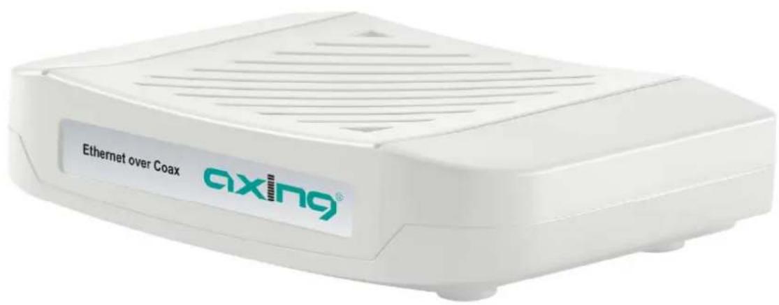
Table of contents
1. Product description .... 4
1.1. Compatibility ....5
1.2. Scope of delivery....6
1.3. Connectors and LED indicators on the rear panel 7
2. Mounting 8
3. Installation....9
3.1. Power supply 9
3.2. Connection to the antenna socket (G.hn) 9
3.3. Ethernet connections 9
3.4. WiFi access to EOC 2-31....10
3.5. Network connections....11
4. EoC applications....12
4.1. Internet from cable network operator....12
4.1.1. The principle....12
4.1.2. The implementation....13
4.2. Internet from telephone operator 14
4.2.1. Amplifier with switchable return path....14
4.2.2. Amplifier without switchable return path....15
4.3. Feeding in a SAT-IF distribution structure....16
4.3.1. At the terrestrial input of a multiswitch....16
4.3.2. At the subscriber input of a multiswitch....17
4.3.3. With combiner for a SAT system with QUAD-LNB 18
5. Configuration of EOC 2-31....19
5.1. Access to the graphical user interface 19
5.2. Information....19
5.3. Network....20
5.4. Radio 21
5.5. 2,4-GHz-Band VAP (Virtual Access Point) 22
5.5.1. Further 2,4-GHz Virtuell Access Points 23
5.6. 5-GHz-Band VAP (Virtual Access Point)....24
5.6.1. Further 5-GHz Virtuell Access Points 25
5.7. Configuring Virtual LANs (VLAN) 26
5.8. Active Changes....27
5.9. User 27
5.10. Firmware Upgrade 28
5.11. Restoring the factory settings....28
6. Technical data....29

WARNING
Observe the safety instructions supplied with the device! They are also available at the following Internet address: https://download.axing.com/BAs/Sicherheitshinweise_9sprachig.pdf
→ Use the device only as described in these operating instructions and in particular in accordance with the state of the art. If the device is used for other purposes, no warranty will be assumed!

Declaration of Conformity:
Hereby AXING AG declares that the marked products comply with the valid guidelines.
EOC 2-31: Hereby AXING AG declares that the device is in compliance with Directive 2014/53/EU. The full text of the EU declaration of conformity is available at the following internet address: https://axing.com/en/ce.

WEEE Nr. DE26869279 | Electrical and electronic components must not be disposed of as residual waste, it must be disposed of separately.
1. Product description
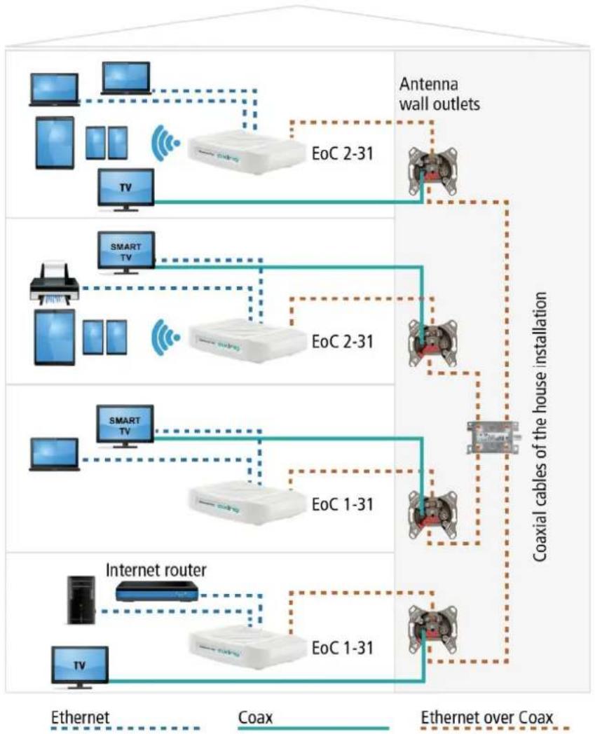
The EOC 1-31 and EOC 2-31 respectively, use the G.hn standard to build an Ethernet-over-coax network via the coaxial cables of the house installation. Television and radio will continue to broadcast over it.
flowchart
graph TD
    A["EcoC 2-31"] --> B["TV"]
    B --> C["Smart TV"]
    C --> D["TV"]
    D --> E["TV"]
    E --> F["EoC 1-31"]
    F --> G["Internet router"]
    G --> H["TV"]
    H --> I["EoC 1-31"]
    I --> J["EoC 2-31"]
    J --> K["TV"]
    K --> L["EoC 2-31"]
    L --> M["TV"]
    M --> N["EoC 1-31"]
    N --> O["EoC 2-31"]
    O --> P["TV"]
    P --> Q["EoC 2-31"]
    Q --> R["EoC 1-31"]
    R --> S["EoC 2-31"]
    S --> T["TV"]
    T --> U["EoC 2-31"]
    U --> V["EoC 1-31"]
    V --> W["EoC 2-31"]
    W --> X["EoC 1-31"]
    X --> Y["EoC 2-31"]
    Y --> Z["EoC 2-31"]
    Z --> AA["EoC 1-31"]
    AA --> AB["EoC 2-31"]
    AB --> AC["EoC 1-31"]
    AC --> AD["EoC 2-31"]
    AD --> AE["EoC 2-31"]
    AE --> AF["EoC 1-31"]
    AF --> AG["EoC 2-31"]
    AG --> AH["EoC 2-31"]
    AH --> AI["EoC 1-31"]
    AI --> AJ["EoC 2-31"]
    AJ --> AK["EoC 2-31"]
    AK --> AL["EoC 1-31"]
    AL --> AM["EoC 2-31"]
    AM --> AN["EoC 2-31"]
    AN --> AO["EoC 1-31"]
    AO --> AP["EoC 2-31"]
    AP --> AQ["EoC 2-31"]
    AQ --> AR["EoC 1-31"]
    AR --> AS["EoC 2-31"]
    AS --> AT["EoC 2-31"]
    AT --> AU["EoC 1-31"]
    AU --> AV["EoC 2-31"]
    AV --> AW["EoC 2-31"]
    AW --> AX["EoC 1-31"]
    AX --> AY["EoC 2-31"]
    AY --> AZ["EoC 2-31"]
    AZ --> BA["EoC 1-31"]
    BA --> BB["EoC 2-31"]
    BB --> BC["EoC 2-31"]
    BC --> BD["EoC 1-31"]
    BD --> BE["EoC 2-31"]
    BE --> BF["EoC 2-31"]
    BF --> BG["EoC 1-31"]
    BG --> BH["EoC 2-31"]
    BH --> BI["EoC 2-31"]
    BI --> BJ["EoC 1-31"]
    BJ --> BK["EoC 2-31"]
    BK --> BL["EoC 2-31"]
    BL --> BM["EoC 1-31"]
    BM --> BN["EoC 2-31"]
    BN --> BO["EoC 2-31"]
    BO --> BP["EoC 1-31"]
    BP --> BQ["EoC 2-31"]
    BQ --> BR["EoC 2-31"]
    BR --> BS["EoC 1-31"]
    BS --> BT["EoC 2-31"]
    BT --> BU["EoC 2-31"]
    BU --> BV["EoC 1-31"]
    BV --> BW["EoC 2-31"]
    BW --> BX["EoC 2-31"]
    BX --> BY["EoC 1-31"]
    BY --> BZ["EoC 2-31"]
    AY <-->|Coaxial cables of the house installation| Z
EOC 1-31 and EOC 2-31 use the return path range of 5...65 MHz. Therefore, all components in the distribution network must be suitable for return path.
1.1. Compatibility
When selecting devices, make sure that they are compatible with each other( √ ).
| Third generation Second generation First generation | |||||||||||||||||
| EOC 1-31 | EOC 2-31 | EOC 1-32 | EOC 2-32 | EOC 30-01 | EOC 30-21 | EOC 30-02 | EOC 30-03 | EOC 1-11 | EOC 2-11 | EOC 20-01 | EOC 20-02 | EOC 1-01 | EOC 2-01 | EOC 10-01 | EOC 10-02 | ||
| Third generation | EOC 1-31 | √ | √ | XXXX | XX | √ | XXXX | XXXX | |||||||||
| EOC 2-31 | √ | √ | XXXX | XX | √ | XXXX | XXXX | ||||||||||
| EOC 1-32 | XX | √ | √ | XXXX | XXXX | XXXX | |||||||||||
| EOC 2-32 | XX | √ | √ | XXXX | XXXX | XXXX | |||||||||||
| EOC 30-01 | XX | XXXX | X | √ | XXXX | XXXX | |||||||||||
| EOC 30-21 | XX | XXXX | X | √ | XXXX | XXXX | |||||||||||
| EOC 30-02 | XX | XX | √ | √ | XXXX | XXXX | |||||||||||
| EOC 30-03 | XX | XX | √ | √ | XXXX | XXXX | |||||||||||
| Second generation | EOC 1-11 | √ | √ | XXXX | XX | √ | √ | XXXXXX | |||||||||
| EOC 2-11 | √ | √ | XXXX | XX | √ | √ | XXXXXX | ||||||||||
| EOC 20-01 | XX | XXXX | XXXX | XX | √ | XXXX | |||||||||||
| EOC 20-02 | XX | XXXX | XXXX | √ | XXXX | ||||||||||||
| First generation | EOC 1-01 | XX | XXXX | XXXX | XXX | √ | √ | X | X | ||||||||
| EOC 2-01 | XX | XXXX | XXXX | XXX | √ | √ | X | X | |||||||||
| EOC 10-01 | XX | XXXX | XXXX | XXXX | XXX | √ | |||||||||||
| EOC 10-02 | XX | XXXX | XXXX | XXXX | XX | X | |||||||||||

1.2. Scope of delivery
- EOC 1-31 or EOC 2-31
- CAT5 ethernet cable
• 12 VDC power adapter for power supply - Quick start guide
1.3. Connectors and LED indicators on the rear panel
| Port Name/Button Type Function | |||
| A | G.hn F EoC signal | ||
| B1 | TV F TV signal (use depends on the application (see 4, page 12) | ||
| C | LAN1/LAN2 | RJ-45 | Connect to PC or STB or other Ethernet devices |
| D2 | R | - | Reset Button |
| E | DC12V | DC | Connect to the power adapter plug |
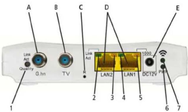
| LED | Status | |||
| On | Flashing | Off | ||
| 1 | Link/Act | Quality | Linked | Receive or transmit | Disconnected or Link fail |
| 2 | LAN2 Link/Aci | Linked | Receive or transmit | Disconnected or Link fail |
| 3 | LAN2 1000 | 1000 Mbps | N/A | 100 Mbps |
| 4 | LAN1 Link/Aci | Linked | Receive or transmit | Disconnected or Link fail |
| 5 | LAN1 1000 | 1000 Mbps | N/A | 100 Mbps |
| 6^2 | WiFi on | Receive or transmit | WiFi off | |
| 7 | PWR | Power supply on | N/A | Power supply off |
LED 1 (Link/Act | Quality) also shows the quality of the EoC connection: Green: High
Orange: Medium
Red: Low
2. Mounting
The devices can be used as table top units or mounted on the wall using two matching screws.

Used as table top unit

natural_image
White rectangular electronic device with a perforated panel and two threaded connectors at the bottom (no text or symbols visible)Mounted on the wall
3. Installation

3.1. Power supply
→ Connect the AC adapter to the DC12V connector and plug the AC adapter into a power outlet.
3.2. Connection to the antenna socket (G.hn)
→Use a coaxial cable to connect the G.hn connector to the antenna socket.
IMPORTANT
Which connector socket of an antenna outlet you have to use depends on the respective application and the existing coaxial cable network (cable connection, satellite TV or DVB-T/T2) in your house (see Chapter 4 EoC applications on page 12).
3.3. Ethernet connections
→ Use the supplied Ethernet cable to connect a router, PC, notebook computer, etc. to the LAN1 or LAN2 port.
→ If necessary, use another Cat-5 Ethernet cable to connect another device. You can also connect a switch for even more connectivity.
3.4. WiFi access to EOC 2-31
The EOC 2-31 offers two WiFi bands, 2.4 GHz and 5 GHz.
Depending on which technology your end device supports, you log on to the respective band.
The factory SSIDs of the 2.4 GHz and 5 GHz WiFi band and the password are printed on the bottom of the device.

3.5. Network connections
The devices require a DHCP server ex factory. This is e.g. included in a standard internet router (EOC 2-31 allows you to configure the network settings, see chapter 5 on page 19).
Each device can be connected to two ^3 Ethernet-capable devices (PCs, notebooks, servers, printers, smart TVs, etc.). The devices communicate in peer-to-peer mode. That is, each EOC can communicate with every other EOC in the network.
In the example shown, the router has the IP address 198.168.78.1 and assigns additional IP addresses to the connected devices.

flowchart
graph TD
    A["Internet-Router/DHCP-Server"] -->|IP = 192.168.78.1| B["EoC 1-31"]
    A -->|IP = 192.168.78.2| C["EoC 1-31"]
    A -->|IP = 192.168.78.3| D["SMART TV"]
    A -->|IP = 192.168.78.4| E["EoC 1-31"]
    A -->|IP = 192.168.78.9| F["EoC 2-31"]
    A -->|IP = 192.168.78.10| G["EoC 2-31"]
    H["Ethernet over Coax"] --> I["G.hn: MAC = 00-01-40-3E-xx-01"]
    H --> J["IP = 192.168.78.5"]
    H --> K["WiFi: MAC = 00-01-40-41-xx-01"]
    H --> L["IP = 192.168.78.6"]
    M["Ethernet"] --> N["G.hn: MAC = 00-01-40-3E-xx-02"]
    M --> O["IP = 192.168.78.7"]
    M --> P["WiFi: MAC = 00-01-40-41-xx-02"]
    M --> Q["IP = 192.168.78.8"]
The devices connected to LAN1 / 2 receive their IP addresses from the DHCP server (usually on the Internet router). Devices connected via WiFi also receive their IP addresses from the DHCP server..
EOC 1-11 receive no IP addresses. The EOC 2-11 receive two IP addresses each from the DHCP server (one for G.hn and one for WiFi).
Recommendation: Make a note of the MAC addresses of the EOC 2-31 and the associated IP addresses.
4. EoC applications
EOC 1-31 and EOC 2-31 communicate with each other in the return path range of 5...65 MHz. All components in the distribution structure must therefore be suitable for the return path. This applies in particular to the antenna wall outlets, the passive distribution material and to SAT multiswitches.
4.1. Internet from cable network operator
If you use Internet access from a cable network operator, you will need a DOCSIS-enabled cable modem or router.
4.1.1. The principle
TV and radio from the cable network operator are forwarded to the distribution network via the passage of the BSD 963-13N and via the TZU 40-04.

flowchart
graph LR
    A["Internet"] --> B["DOCSIS Router"]
    B --> C["BSD 963-13N"]
    C --> D["TV and Internet from CATV provider"]
    D --> E["TV and Internet to other EoC x-31"]
    E --> F["TZU 40-04 (TZU 40-03)"]
    F --> G["EoC x-31"]
    G --> H["5...65 (EoC) | 85...1006 MHz"]
    H --> I["blocking depth @ 5...65 MHz: 45 dB"]
    I --> J["5...1006 MHz (DOCSIS)"]
    J --> K["blocking depth @ 5...65 MHz: 60 dB"]
The cable network operator's IP data is received at the modem port of the BSD 963-13N by means of a DOCSIS router and transmitted via Ethernet to an EOC 1-31. The EOC modulates the IP data and feeds the data into the distribution network via an EoC inserter TZU 40-04. The data can be received on the other EoC devices in the same network.
Important: The use of a BSD 963-13N antenna socket and a TZU 40-03/-04 inserter is mandatory in order to achieve sufficient blocking depth for the frequency range from 5...65 MHz. Otherwise it may cause interferences in the cable network.
4.1.2. The implementation
In the example a BSD 963-13N is installed in apartment 4. The IP data from the cable network operator are received at the modem port of the BSD using a DOCSIS router and forwarded via Ethernet to an EOC 1-31. The EOC modulates the IP data and feeds them into the distribution network via a TZU 40-04 feeder. The data can be received on the other EOC devices.

flowchart
graph TD
    subgraph App_1
        A["App. 1"] --> B["BVS 20-69"]
        B --> C["BVE 4-02P"]
        C --> D["QEW 5-50"]
        D --> E["IP"]
    end

    subgraph App_3
        F["App. 3"] --> G["BSD 963-13N"]
        G --> H["DOCSIS-Router"]
        H --> I["EoC 1-31"]
        I --> J["85...1006 MHz"]
        J --> K["TZU 40-04 (TZU 40-03)"]
        K --> L["EoC 2-31"]
        L --> M["BSD 963-00N"]
        M --> N["BAB 4-02P"]
        N --> O["EoC 2-31"]
        O --> P["BSD 963-00N"]
    end

    subgraph App_4
        Q["Smart TV"] --> R["EoC 2-31"]
        R --> S["BSD 963-00N"]
        S --> T["EoC 2-31"]
        T --> U["BSD 963-00N"]
        U --> V["BAB 4-02P"]
        V --> W["EoC 2-31"]
    end

    style App_1 fill:#f9f,stroke:#333
    style App_3 fill:#f9f,stroke:#333
    style App_4 fill:#ccf,stroke:#333
    style App_5 fill:#cfc,stroke:#333
    style App_6 fill:#fcc,stroke:#333
    style App_7 fill:#cff,stroke:#333
    style App_8 fill:#ffc,stroke:#333
    style App_9 fill:#fcc,stroke:#333
    style App_10 fill:#ffc,stroke:#333
    style App_11 fill:#cfc,stroke:#333
    style App_12 fill:#fcc,stroke:#333
    style App_13 fill:#cfc,stroke:#333
    style App_14 fill:#fcc,stroke:#333
    style App_15 fill:#cfc,stroke:#333
    style App_16 fill:#cfc,stroke:#333
    style App_17 fill:#cfc,stroke:#333
    style App_18 fill:#cfc,stroke:#333
    style App_19 fill:#cfc,stroke:#333
    style App_20 fill:#fcc,stroke:#333
    style App_21 fill:#cfc,stroke:#333
    style App_22 fill:#cfc,stroke:#333
    style App_23 fill:#cfc,stroke:#333
    style App_24 fill:#cfc,stroke:#333
    style App_25 fill:#cfc,stroke:#333
    style App_26 fill:#cfc,stroke:#333
    style App_27 fill:#cfc,stroke:#333
    style App_28 fill:#cfc,stroke:#333
    style App_29 fill:#cfc,stroke:#333
    style App_30 fill:#cfc,stroke:#333
    style App_31 fill:#cfc,stroke:#333
    style App_32 fill:#cfc,stroke:#333
    style App_33 fill:#cfc,stroke:#333
    style App_34 fill:#cfc,stroke:#333
    style App_35 fill:#cfc,stroke:#333
    style App_36 fill:#cfc,stroke:#333
    style App_37 fill:#cfc,stroke:#333
    style App_38 fill:#cfc,stroke:#333
    style App_39 fill:#cfc,stroke:#333
    style App_40 fill:#fcc,stroke:#333
For the connection of the other EOC devices in the example multimedia antenna wall outlets BSD 963-00N are installed. The G.hn connectors of the EOC are connected to the DATA connector of the antenna wall outlet. TV devices are connected to the TV port of the antenna wall outlet.
Important: The use of a BSD 963-13N antenna socket and a TZU 40-03/-04 inserter is mandatory in order to achieve sufficient blocking depth for the frequency range from 5...65 MHz. Otherwise it may cause interferences in the cable network.
4.2. Internet from telephone operator
4.2.1. Amplifier with switchable return path
The IP data from the telephone provider is received by a router and forwarded to an EOC 1-31. The feeding of the IP signal into the TV distribution network takes place via a return path suitable antenna wall outlet.
The example above shows the connection to a multimedia antenna wall outlet BSD 963-14N. The EOC's G.hn connectors are connected to the DATA connector of the antenna wall outlet. TV devices are connected to the TV connector of the antenna wall outlet.
Connection to a multimedia antenna wall outlet BSD 963-14N:
The EOC's G.hn connectors are connected to the DATA connector of the antenna wall outlet. TV devices are connected to the TV connector of the EOC.

flowchart
graph TD
    A["IP"] --> B["TZU 19-65"]
    B --> C["BVE 4-02P"]
    C --> D["BSD 963-14N + TZU 3-01"]
    D --> E["SMART TV"]
    E --> F["EoC 1-31"]
    F --> G["www"]
    H["Coax"] --> I["the EOC."]
    J["Ethernet over Coax"] --> K["AMPIER with switched off return path"]
    L["Ethernet"] --> M["Connection to a CATV antenna wall outlet BSD 21-14N: The G.hn connectors of the EOC are connected to the TV connection of the antenna wall outlet using an EOC TZU 40-04 combiner. TV devices are connected to the TV connection of the EOC combiner."]
    M --> N["BSD 21-14N + TZU 3-01"]
    N --> O["SMART TV"]
    O --> P["EoC 2-31"]
    P --> Q["Smart TV"]
    Q --> R["OeC 2-31"]
Important: A high-pass filter TZU 19-68 must be installed in the coaxial feed line (at amplifier output). In addition, the return path of the amplifier must be switched off. Otherwise it may cause interferences in the cable network.
4.2.2. Amplifier without switchable return path
If it is not possible to switch off the return path, a high-pass filter TZU 19-65 and a BSD 963-13N antenna wall outlet must be installed at the output of the amplifier.

flowchart
graph TD
    A["HÜP"] --> B["Verstärker ohne abschaltbaren Rückkanal Amplifier without switchable return path"]
    B --> C["BSD 963-13N"]
    C --> D["TZU 19-65"]
    D --> E["BSD 963-14N + TZU 3-01"]
    E --> F["SMART TV"]
    F --> G["EoC 1-31"]
    G --> H["WWW"]
    C --> I["BSD 963-14N + TZU 3-01"]
    I --> J["EoC 1-31"]
    J --> K["SMART TV"]
    K --> L["EoC 1-31"]
    L --> M["BSD 963-14N + TZU 3-01"]
    M --> N["EoC 1-31"]
    N --> O["SMART TV"]
    O --> P["EoC 1-31"]
    P --> Q["WWW"]
    style A fill:#f9f,stroke:#333
    style B fill:#ccf,stroke:#333
    style C fill:#cfc,stroke:#333
    style D fill:#fcc,stroke:#333
    style E fill:#cff,stroke:#333
    style F fill:#ffc,stroke:#333
    style G fill:#cfc,stroke:#333
    style H fill:#fcc,stroke:#333
    style I fill:#ffc,stroke:#333
    style J fill:#cfc,stroke:#333
    style K fill:#ffc,stroke:#333
    style L fill:#cfc,stroke:#333
    style M fill:#ffc,stroke:#333
    style N fill:#cfc,stroke:#333
    style O fill:#cfc,stroke:#333
    style P fill:#cfc,stroke:#333
    style Q fill:#cfc,stroke:#333
Important: The use of a BSD 963-13N antenna socket and the high-pass filter TZU 19-65 is mandatory in order to achieve sufficient blocking depth for the frequency range from 5...65 MHz. Otherwise it may cause interferences in the cable network.
4.3. Feeding in a SAT-IF distribution structure
For feeding into a SAT IF distribution structure, IP signals from a telephone service provider or a cable network operator can be used.
Important: If additional CATV signals of a cable operator are fed into the terrestrial branch, then sufficient locking depth of ca. 100 dB for the frequency range of 5 ... 65 MHz must be achieved. Otherwise it may cause interferences in the cable network. Proceed as shown in the examples for amplifiers with or without switchable return path, see 4.1 at page 12.
4.3.1. At the terrestrial input of a multiswitch
The IP data from the telephone company is received by a router and forwarded to an EOC 1-31. The EOC modulates the IP data and feeds it via a TZU 40-04 into the terrestrial input of the multiswitch. The IP data can be received at the other EOC devices.

flowchart
graph TD
    subgraph_Smart_TV["Smart TV"]
        A["OEC 1-31"] --> B["ETR00CL CATV 258...1006 MHz"]
        B --> C["SAT"]
        C --> D["SSD 5-00 FM"]
        D --> E["Sat | CATV + EoC"]
    end

    subgraph_SmartTV["Smart TV"]
        F["TZU 40-64 (TZU 40-63)"] --> G["TZU 19-65"]
        G --> H["WWW"]
        H --> I["EoC 1-31"]
        I --> J["SSD 5-00"]
        J --> K["QEW 3-12"]
        K --> L["QEW 5-10"]
        L --> M["QEW 3-12"]
    end

    subgraph SmartTV_CATV
        N["Sat"] --> O["ETR00CL CATV 258...1006 MHz"]
        P["Sat"] --> Q["ETR00CL CATV 85...1006 MHz"]
        R["Sat"] --> S["ETR00CL CATV 40-04"]
        T["Sat"] --> U["ETR00CL CATV + EoC"]
    end

    style Smart_TV fill:#f9f,stroke:#333
    style SmartTV_CATV fill:#bbf,stroke:#333
In the example on the left, the devices are connected as follows:
• G.hn connector of the EOC at the TV connector of the antenna wall outlet
- CATV input of the TV device on the TV port of the EOC (this prevents reception of channels below 258 MHz)
• SAT input of the TV device at the SAT connection of the antenna wall outlet
- Radio set at the FM connector of the antenna wall outlet
In the example on the right, the devices are connected as follows:
• G.hn connections of the EOC using an EOC switch TZU 40-04 at the TV connector of the antenna wall outlet
- CATV input of the TV device on the TV connector of the EOC crossover (this means that 85 MHz channels cannot be received)
- SAT input of the TV device at the SAT connector of the antenna wall outlet
- Radio set at the FM connector of the antenna wall outlet
4.3.2. At the subscriber input of a multiswitch

flowchart
graph TD
    subgraph Satellite
        A["WWW"] --> B["SSD 5-00"]
        B --> C["EOC 1-31"]
        C --> D["Kein terr. Empfang möglich"]
        D --> E["SWE 20-01"]
        E --> F["TZU 19-66"]
        F --> G["QEW 3-12"]
        G --> H["TZU 40-04 (TZU 40-03)"]
        H --> I["TZU 19-65"]
        I --> J["TZU 40-04 (TZU 40-03)"]
        J --> K["TZU 19-65"]
        K --> L["QEW 5-10"]
        L --> M["TZU 40-04 (TZU 40-03)"]
        M --> N["TZU 19-65"]
        N --> O["TZU 40-04 (TZU 40-03)"]
        O --> P["TZU 19-65"]
        P --> Q["TZU 40-04 (TZU 40-03)"]
        Q --> R["TZU 19-65"]
        R --> S["TZU 40-04 (TZU 40-03)"]
        S --> T["TZU 19-65"]
        T --> U["TZU 40-04 (TZU 40-03)"]
        U --> V["TZU 19-65"]
        V --> W["TZU 40-04 (TZU 40-03)"]
        W --> X["TZU 19-65"]
        X --> Y["TZU 40-04 (TZU 40-03)"]
        Y --> Z["TZU 19-65"]
        Z --> AA["TZU 40-04 (TZU 40-03)"]
        AA --> AB["TZU 19-65"]
        AB --> AC["TZU 40-04 (TZU 40-03)"]
        AC --> AD["TZU 19-65"]
        AD --> AE["TZU 40-04 (TZU 40-03)"]
        AE --> AF["TZU 19-65"]
        AF --> AG["TZU 40-04 (TZU 40-03)"]
        AG --> AH["TZU 19-65"]
        AH --> AI["TZU 40-04 (TZU 40-03)"]
        AI --> AJ["TZU 19-65"]
        AJ --> AK["TZU 40-04 (TZU 40-03)"]
        AK --> AL["TZU 19-65"]
        AL --> AM["TZU 40-04 (TZU 40-03)"]
        AM --> AN["TZU 19-65"]
        AN --> AO["TZU 40-04 (TZU 40-03)"]
        AO --> AP["TZU 19-65"]
        AP --> AQ["TZU 40-04 (TZU 40-03)"]
        AQ --> AR["TZU 19-65"]
        AR --> AS["TZU 40-04 (TZU 40-03)"]
        AS --> AT["TZU 19-65"]
        AT --> AU["TZU 40-04 (TZU 40-03)"]
        AU --> AV["TZU 19-65"]
        AV --> AW["TZU 40-04 (TZU 40-03)"]
        AW --> AX["TZU 19-65"]
        AX --> AY["TZU 40-04 (TZU 40-03)"]
        AY --> AZ["TZU 19-65"]
        AZ --> BA["TZU 40-04 (TZU 40-03)"]
        BA --> BB["TZU 19-65"]
        BB --> BC["TZU 40-04 (TZU 40-03)"]
        BC --> BD["TZU 19-65"]
        BD --> BE["TZU 40-04 (TZU 40-03)"]
        BE --> BF["TZU 19-65"]
        BF --> BG["TZU 40-04 (TZU 40-03)"]
        BG --> BH["TZU 19-65"]
        BH --> BI["TZU 40-04 (TZU 40-03)"]
        BI --> BJ["TZU 19-65"]
        BJ --> BK["TZU 40-04 (TZU 40-03)"]
        BK --> BL["TZU 19-65"]
        BL --> BM["TZU 40-04 (TZU 40-03)"]
        BM --> BN["TZU 19-65"]
        BN --> BO["TZU 40-04 (TZU 40-03)"]
        BO --> BP["TZU 19-65"]
        BP --> BQ["TZU 40-04 (TZU 40-03)"]
        BQ --> BR["TZU 19-65"]
        BR --> BS["TZU 40-04 (TZU 40-03)"]
        BS --> BT["TZU 19-65"]
        BT --> BU["TZU 40-04 (TZU 40-03)"]
        BU --> BV["TZU 19-65"]
        BV --> BW["TZU 40-04 (TZU 40-03)"]
        BW --> BX["TZU 19-65"]
        BX --> BY["TZU 40-04 (TZU 40-03)"]
        BY --> BZ["TZU 19-65"]
        BZ --> CA["TZU 40-04 (TZU 40-03)"]
        CA --> CB["TZU 19-65"]
        CB --> CC["TZU 40-04 (TZU 40-03)"]
        CC --> CD["TZU 19-65"]
        CD --> CE["TZU 40-04 (TZU 40-03)"]
        CE --> CF["TZU 19-65"]
    end
In the example, the EOC signals are fed in at the first subscriber port of a multiswitch.
The signals are split at the subscriber port with a SAT combiner SWE 20-01. Ethernet over Coax reaches the terrestrial input of the multiswitch via the upper part of the combiner. This ensures that all other EOC devices in the house are provided with Internet.
At the lower branch of the turnout the TZU 19-66 blocks the EOC signals. SAT signals are forwarded as usual to the SSD 5-00 and the connected TV set.
4.3.3. With combiner for a SAT system with QUAD-LNB

flowchart
graph TD
    A["SOU 4-x1"] --> B["QEW 4-20"]
    B --> C["4 x TZU 19-66"]
    C --> D["SWE 40-01"]
    D --> E["EoC 1-31"]
    E --> F["SSD 5-00"]
    F --> G["SMART TV"]
    G --> H["WWW"]
    H --> I["EoC 1-11"]
    I --> J["QEW 4-20"]
    J --> K["4 x TZU 19-66"]
    K --> L["SWE 40-01"]
    L --> M["EoC 2-31"]
    M --> N["SSD 5-00"]
    N --> O["SAT TV"]
    O --> P["EoC 2-31"]
    P --> Q["SSD 5-00"]
    Q --> R["SAT TV"]
    R --> S["EoC 1-31"]
    S --> T["SSD 5-00"]
    T --> U["EoC 1-31"]
    U --> V["SSD 5-00"]
The IP data from the telephone provider is received with the help of a router and forwarded to an EOC 1-11 via LAN, for example. The EOC modulates the IP data and feeds it via the terrestrial input of a SWE 40-01 combiner. The IP data can be received at the other EOC devices (e.g. EOC 2-31) at the TV output of a SAT antenna socket SSD 5-00.
5. Configuration of EOC 2-31
The configuration of the EOC 2-31 is done via a graphical user interface. Eoc 1-31 can not be configured.
5.1. Access to the graphical user interface
To access the EOC 2-31, your PC must be on the same IPv4 network.
The EOC 2-31 receive two IP addresses each from the DHCP server (one for G.hn and one for WiFi).
Enter the WiFi IP address of the EOC 2-31 in the address bar of your browser. The EOC 2-31 prompts you for a password in a window.

The password is printed on the bottom of the device.
5.2. Information
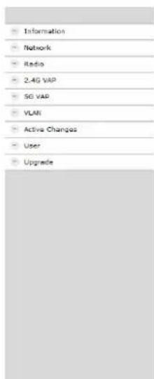
The window contains the navigation on the left and displays the contents of the selected entry on the right. Information about the device is summarized in the Information window.
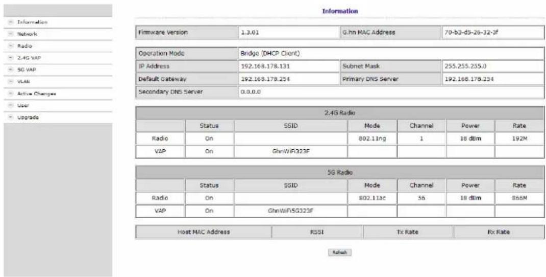
The upper part shows the firmware version and G.hn MAC address (refer to 3.5 on page 9), and IP address data obtained from the DHCP server or set manually. The most important parameters for the two WIFI bands 2.4G Radio = 2.4 GHz band and 5G Radio = 5 GHz band are listed below.
5.3. Network


In the NET window, the Operation Mode is set to Bridge (DHCP Client) at factory. As a result, the EOC receives its IP address data from the DHCP server. The devices connected to the EOC also receive their IP address data from the DHCP server.
→ If you configure Bridge (Static IP) as the Operation Mode, additional fields are displayed. Enter the IP address data of the EOC manually.
→Usually you also have to enter the IP address data of the connected devices manually.


→Click Update to apply the entered values.
Important: This does not yet activate the changes in the EOC. Only when you activate them on the Active Changes page will the changes actually be applied to the device (see 5.8 on page 27).
5.4. Radio
The basic settings of the two WIFI bands (2.4 GHz and 5 GHz) are configured at RADIO.
| Information |
| Network |
| Radio |
| 2.4G VAP |
| 5G VAP |
| VLAN |
| Active Changes |
| User |
| Upgrade |
| RADIO | |||
| Client Isolation | Disable | Hide SSID | Disable |
| 2.4G Setting | |||
| WIFI Service | Enable | Maximum Tx Power | 22 |
| Mode | auto | Channel | auto |
| SG Setting | |||
| WIFI Service | Enable | Maximum Tx Power | 20 |
| Bandwidth | auto | Channel | auto |

Client Isolation
- Enable prevents WIFI clients from seeing each other and establishing a connection to each other.
- Disable enables WIFI clients to see each other and establish a connection to each other.
Hide SSID
- Enable The WIFI network name is not sent, so it is not visible to WIFI clients.
- Disable The WIFI network name is sent, so it can be seen by WIFI clients.
WIFI Service
- Enable activates the WIFI.
- Disable switches off the WIFI.
Maximum Tx Power
The maximum transmission power can be adjusted here. The maximum permissible values are entered at the factory. If WIFI networks in close proximity to each other cause interference, the transmission power can be reduced.
Channel
Since there are usually several WIFI access points in the immediate vicinity (e.g. those of neighbours), the frequency bands are additionally divided into channels.
• Auto: The EOC itself determines the best channel with the least radio traffic.
• 1 ... 13 If necessary, the WIFI performance can be improved by manual adjustment.
Mode | Bandwidth
• The EOC can operate in the 5 GHz band with 20 MHz, 40 MHz, or 80 MHz bandwidth.
• The EOC can operate in the 2.4 GHz band with 20 MHz or 40 MHz bandwidth.
- In the Auto setting the EOC automatically selects the correct bandwidth. In manual mode the bandwidth is fixed.
→Click Update to apply the entered values.
Important: This does not yet activate the changes in the EOC. Only when you activate them on the Active Changes page will the changes actually be applied to the device (see 5.8 on page 27).
5.5. 2,4-GHz-Band VAP (Virtual Access Point)
In the 2.4G VAP window, you configure the parameters of the 2.4 GHz band.


Service
- Enable switches on the 2.4 GHz band.
- Disable switches off the 2.4 GHz band.
SSID
→Enter the name of your WIFI network here.
The name can be up to 15 characters long.
Security Mode
Define the security of your WIFI network here.
- Open: No security
- WPA-PSK/WPA2-PSK Mixed: Wi-Fi-Protected-Acces with Pre-Shared-Key or Wi-Fi-Protected-Acces with Pre-Shared-Key are used depending on the terminal device.
• WPA3 End devices must support Wi-Fi Protected Access 3
Pre-Shared Key
- Specify a WIFI security key for the WIFI connection here.
- Note: The pre-shared key must be at least 8 and at most 16 characters long and must not contain any special characters, only numbers and letters.
Cypher
TKIP (Temporal Key Integrity Protocol) and CCMP (Counter Mode with Cipher Block Chaining Message Authentication Code Protocol and AES (Advanced Encryption Standard) are encryption methods.
• Auto detects (depending on what the terminal device supports) either CCMP(AES) or TKIP.
- CCMP(AES), the Advanced Encryption Standard is used.
• TKIP, the Temporal Key Integrity Protocol is used.
→Click Update to apply the entered values.
Important: This does not yet activate the changes in the EOC. Only when you activate them on the Active Changes page will the changes actually be applied to the device (see 5.8 on page 27).
5.5.1. Further 2,4-GHz Virtuell Access Points
The EOC supports up to four Virtual Access Points (2.4G VAP 1 to 2.4G VAP 4). So a further three Virtual Access Points can be configured.
For 2.4G VAP 2, 2.4G VAP 3, and 2.4G VAP 4, select Enable in the Service box. The parameters of the other VAPs appear.

→Click Update to apply the entered values.
Important: This does not yet activate the changes in the EOC. Only when you activate them on the Active Changes page will the changes actually be applied to the device (see 5.8 on page 27).
5.6. 5-GHz-Band VAP (Virtual Access Point)
In the 5G VAP window, you configure the parameters of the 5 GHz band.

![5G VAP 5G VAP 1 Service Enable SSID channel:5G223F Security Mode [mBA-PSK/6%BA2-PSK Mixed] Cipher Auto Pre-Shared key 845934m 5G VAP 2 Service Disable 5G VAP 3 Service Disable 5G VAP 4 Service Disable Update](/content/2026/05/859613/images/2dc3e2a669274589609744aaae80942f24c500f67c9019456d44b33c9fb0902c.jpg)
Service
- Enable switches on the 5 GHz band.
- Disable switches off the 5 GHz band.
SSID
→Enter the name of your WIFI network here.
The name can be up to 15 characters long.
Security Mode
Define the security of your WIFI network here.
- Open: No security
- WPA-PSK/WPA2-PSK Mixed: Wi-Fi-Protected-Acces with Pre-Shared-Key or Wi-Fi-Protected-Acces with Pre-Shared-Key are used depending on the terminal device.
• WPA3 End devices must support Wi-Fi Protected Access 3
Pre-Shared Key
- Specify a WIFI security key for the WIFI connection here.
- Note: The pre-shared key must be at least 8 and at most 16 characters long and must not contain any special characters, only numbers and letters.
Cypher
TKIP (Temporal Key Integrity Protocol) and CCMP (Counter Mode with Cipher Block Chaining Message Authentication Code Protocol and AES (Advanced Encryption Standard) are encryption methods.
• Auto detects (depending on what the terminal device supports) either CCMP(AES) or TKIP.
- CCMP(AES), the Advanced Encryption Standard is used.
• TKIP, the Temporal Key Integrity Protocol is used.
→Click Update to apply the entered values.
Important: This does not yet activate the changes in the EOC. Only when you activate them on the Active Changes page will the changes actually be applied to the device (see 5.8 on page 27).
5.6.1. Further 5-GHz Virtuell Access Points
The EOC supports up to four Virtual Access Points (5G VAP 1 to 5G VAP 4). So a further three Virtual Access Points can be configured.
For 5G VAP 2, 5G VAP 3, and 5G VAP 4, select Enable in the Service box. The parameters of the other VAPs appear.

→Click Update to apply the entered values.
Important: This does not yet activate the changes in the EOC. Only when you activate them on the Active Changes page will the changes actually be applied to the device (see 5.8 on page 27).
5.7. Configuring Virtual LANs (VLAN)
In the VLAN window, the Tag VLAN field is set to Disable by default.
→ If you want to configure VLANs, select the Enable option.


Priority
Defines the priority (e.g. for traffic shaping). The value can be set between 0 and 7.
VID:
Each VLAN is assigned a unique number, the VID. A device that belongs to the VLAN with VID=1 can communicate with any other device on the same VLAN, but not with a device on another VLAN. The VID can be set between 1 and 4094.
In Rule
- Set one of the VID Matched or Accept All options.
Out Rule
→ Set one of the Untag, Tag or Bypass options.
→Click Update to apply the entered values.
Important: This does not yet activate the changes in the EOC. Only when you activate them on the Active Changes page will the changes actually be applied to the device (see 5.8 on page 27).
5.8. Active Changes
In the Active Changes window, you apply and save the changed settings.

→Click on Active.
The EOC 2-31 is rebooted.
Changes made in the configuration pages are saved.
5.9.User

→In the Current Password field, enter the current password.
→In the New Password field, enter the new password.
→ Confirm the password in the Confirm New Password field.
→Click Update.
The new password is saved and activated in the device.
5.10. Firmware Upgrade
Firmware version
The current version of the firmware can be found in the Information window (see 5.2 on page 19).
Download of the file
You can find firmware updates for download by entering the article in the search field on www.axing.com. On the product page you will find the current firmware in the Downloads tab.
→Download the file to your computer and unpack it.
Upgrade of the Firmware
→ Click on Upgrade in the navigation on the right.
→ Click Browse ... and select the upgrade file.

→Click Start.
The firmware/the driver file is loaded into the EOC and the device is restarted. The new firmware will be activated immediately after restarting the EOC.
5.11. Restoring the factory settings
→ Press the reset button R on the back of the device for a few seconds until the LEDs start flashing. All configuration settings made are reset to the factory settings.
6. Technical data
| Typ EOC 1-31 EOC 2-31 | ||
| Frequency range 5...1218 MHz | ||
| Connectors (G.hn | TV) 2 × F-Buchse | ||
| Frequency range transmission 5...65 MHz | ||
| Frequency range TV bypass 258...1218 MHz | ||
| Max. attn. in coaxial network 77 dB | ||
| Transmission level in coaxial network 113 dBμV ± 1dB | ||
| EoC | ||
| Standard ITU-T G.9960/G.9961 G.hn over Coax | ||
| Net data rate (PHY) 720 Mbps | ||
| Max. number of devices in EoC network 16 | ||
| Interfaces | ||
| Ethernet connectors (LAN) 2 × RJ 45 | ||
| Ethernet standards IEEE 802.3u 100BaseT Fast EthernetIEEE 802.3ab 1000BaseT Gigabit Ethernet | ||
| WiFi standard | - | MIMO 2x2IEEE 802.11b/g/n/a/ac |
| WiFi encryption | - | WEP, WPA/WPA2, WPA/WPA2 m. PSK |
| Common | ||
| Operation voltage | 12 VDC | |
| Power consumption 4 W | 8 W | |
| Operating temperature range (acc. to EN 60065) | 0°C...40°C | |
| Dimensions (W × H × D) appr. | 130 x 95 x 32 mm | |
| External accessories | ||
| Plug-in power supply unit | 100...240 V~/50...60Hz12 V=/0,5 A | 100...240 V~/50...60Hz12 V=/1 A |
| Commission regulation (EU) 2019/1782External plug-in power supply | ||
| EOC 1-31 EOC 2-31 | ||
| Manufacturer's name or trademark commercial registration number and address | Channel Well Technology Co Ltd222 Sec 2 Nankan Rd, Lujhu Township Taoyuan Hsien, 33855 Taiwan | 84573516 | |
| Model identifier 2AAR006F EU 2AAJ012F EU | ||
| Input voltage 100...240 | V | 100...240 V |
| Input AC frequency 50...60 Hz 50...60 Hz | ||
| Output voltage 12,0 | V | 12,0 V |
| Output current 0,5 | A | 1,0 A |
| Output power 6,0 | W | 12,0W |
| Average active efficiency | ||
| Load condition 1 – 100 % ± 2 % 80,4 | % | 82,5% |
| Load condition 2 – 75 % ± 2 % 80,7 | % | 83,7% |
| Load condition 3 – 50 % ± 2 % 80,8 | % | 84,0% |
| Load condition 4 – 25 % ± 2 % 79,1 | % | 83,4% |
| Efficiency at low load (10 %) 72,2 | % | 75,7% |
| No-load power consumption 0,05 | W | 0,04W |


- Ethernet over Coax Peer to Peer
- Inhaltsverzeichnis
- Installation....9
- Client Isolation
- Service
- Priority
- EOC 1-31 and EOC 2-31
- Table of contents
- Product description .... 4
- Mounting 8
- EoC applications....12
- Configuration of EOC 2-31....19
- Technical data....29
- WARNING
- Declaration of Conformity:
- Product description
- Compatibility
- Scope of delivery
- Connectors and LED indicators on the rear panel
- Mounting
- Installation
- Power supply
- Connection to the antenna socket (G.hn)
- IMPORTANT
- Ethernet connections
- WiFi access to EOC 2-31
- Network connections
- EoC applications
- Internet from cable network operator
- The principle
- The implementation
- Internet from telephone operator
- Amplifier with switchable return path
- Amplifier without switchable return path
- Feeding in a SAT-IF distribution structure
- At the terrestrial input of a multiswitch
- At the subscriber input of a multiswitch
- With combiner for a SAT system with QUAD-LNB
- Configuration of EOC 2-31
- Access to the graphical user interface
- Information
- Network
- Radio
- Hide SSID
- WIFI Service
- Maximum Tx Power
- Channel
- Mode | Bandwidth
- 2,4-GHz-Band VAP (Virtual Access Point)
- SSID
- Security Mode
- Pre-Shared Key
- Cypher
- Further 2,4-GHz Virtuell Access Points
- 5-GHz-Band VAP (Virtual Access Point)
- Further 5-GHz Virtuell Access Points
- Configuring Virtual LANs (VLAN)
- VID:
- In Rule
- Out Rule
- Active Changes
- 5.9.User
- Firmware Upgrade
- Firmware version
- Download of the file
- Upgrade of the Firmware
- Restoring the factory settings
- Technical data
Brand : Axing
Model : EoC 2-01
Category : Wi-Fi repeater