
VS-WM202-HDSI - Surveillance Camera Marshall Electronics - Free user manual and instructions
Find the device manual for free VS-WM202-HDSI Marshall Electronics in PDF.


| Product Type | Heavy Duty Exterior PTZ Camera |
| Brand | Marshall Electronics |
| Model | VS-WM202-HDSI |
| Image Sensor | 1/3 Type Exmor CMOS Sensor, 2000K pixels |
| Lens | 20x optical zoom, F=4.7 mm (WIDE) to 94.0 mm (TELE), F1.6 to F3.5 |
| Digital Zoom | 12x (240x with optical zoom) |
| Pan Range | 360° continuous |
| Tilt Range | -90° to 90° |
| Pan Speed | 0.1° to 90°/sec (manual); preset speed up to 150°/sec |
| Tilt Preset Speed | Up to 150°/sec |
| Minimum Illumination | 0.5 lx (color), 0.095 lx (B/W with ICR) |
| Video Output | HD-SDI (BNC) and analog composite |
| Power Supply | DC 24V, 10A (adapter included) |
| Power Consumption | Operating 3A, Max 4A (IR and heater on) |
| Weight | Approx. 12 kg (camera), 15 kg (packing) |
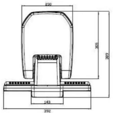
| Dimensions (H x W x D) | Approx. 397 x 230 x 305 mm |
| Environmental Protection | IP66 |
| Operating Temperature | -20°C to 50°C |
| IR LED | 30 pcs Super IR LED, distance up to 200 m |
| Day/Night | ICR filter (True Day & Night) |
| Built-in Accessories | Wiper, fan, heater |
| Presets | 255 programmable |
| Communication | RS-485/RS-422, multiple protocols |
| Certifications | CE, FCC Class A, RoHS, e-Mark |
| Maintenance & Cleaning | Wipe with dry cloth; avoid liquids. No user-serviceable parts inside. |
Frequently Asked Questions - VS-WM202-HDSI Marshall Electronics
User questions about VS-WM202-HDSI Marshall Electronics
0 question about this device. Answer the ones you know or ask your own.
Ask a new question about this device
Download the instructions for your Surveillance Camera in PDF format for free! Find your manual VS-WM202-HDSI - Marshall Electronics and take your electronic device back in hand. On this page are published all the documents necessary for the use of your device. VS-WM202-HDSI by Marshall Electronics.
USER MANUAL VS-WM202-HDSI Marshall Electronics
Marshall Electronics
VS-WM202-HDSDI
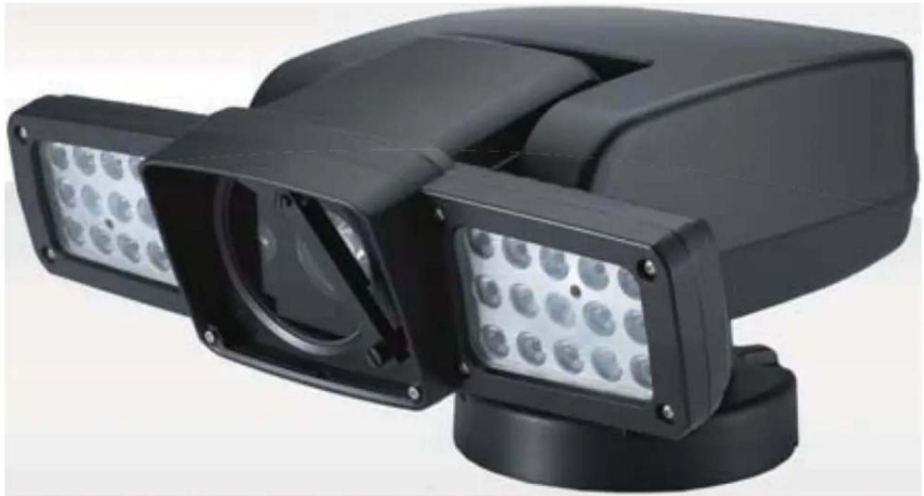
Heavy Duty Exterior PTZ Camera
20x Zoom and IR LED
natural_image
Exterior view of a black rectangular security camera with multiple lenses and a circular display (no text or symbols visible)User Manual
Copyright © May 2012, Marshall Electronics, Inc.
All Rights Reserved. This document may not be copied.
Trademarks
Other trademarks used in this document are registered trademarks or manufacturer or vendor trademarks associated with the products.
Disclaimer
Product options and specifications can be changed without notice. The information in this manual is furnished for informational use only and should not be construed as a commitment by Marshall Electronics, Inc. Marshall Electronics, Inc. assumes no responsibility or liability for any errors or inaccuracies that may appear in this publication.
Safety Precaution
We appreciate your IP Camera Purchase. Before installing the product, please read the following with care.
Make sure to turn off the power before installing the system.
Do not install under the direct sunlight or in dusty areas.
Make sure to use the product within the temperature and humidity specified.
Do not operate the product in the presence of vibrations or strong magnetic fields.
Do not put electrically conducting materials in the ventilation hole.
Do not open the top cover of the products. It may cause a failure or electric shock on the components.
To prevent from overheating, make sure to keep the distance at least 10 cm from the ventilation hole.
✧ Make sure proper voltage before connecting the power.
TABLE OF CONTENTS
1. INFORMATION FOR USER....5
1.1 WARNING....5
1.2 EXPLANATION OF GRAPHICAL SYMBOLS .....5
1.3 FCC COMPLIANCE STATEMENT....5
2. PRECAUTIONS. 6
3. FEATURES. 7
4. SETTINGS & INSTALLATION....8
4.1 Unpacking....8
4.2 DIP Switch Settings . 9
4.3 Cable Connection .....10
-
- 1 Basic Diagram of Cable Connection .....10
4.3.2 Video Output Connection 2....10
- 1 Basic Diagram of Cable Connection .....10
-
- 3 RS-485 / RS-422 Communication Connection .....10
4.3.4 Alarm Connections....10
4.3.5 Power Connections....10
- 3 RS-485 / RS-422 Communication Connection .....10
-
4 Installation. .....11
4.5 Basic Configuration....12
5. MAIN SETUP MENU 13
5.1 Initialize....13
5.2 Motion Setting .....13
5.2.1 Preset....13
5.2.2 Tour....16
5.2.3 Scan....17
5.2.4 Pattern....19
5.2.5 Area....21
5. 2. 6 Alarm. 22
5. 2. 7 Privacy Zone Masking. 23
5.3 Dome Setting .....24
-
- 1 Set the Dome Camera Title. .....25
-
- 2 Set the Power Up Action. .....25
5.3.2 Park Action....25
5.3.4 Display ON/OFF Set 26
- 2 Set the Power Up Action. .....25
-
- 5 Speed by Zoom ON/OFF Set. 26
5.3.6 Auto Flip ON/OFF Set....27
- 5 Speed by Zoom ON/OFF Set. 26
-
- 7 Factory Set....27
5.4 Camera Settings . 27
-
- 1 CAMERA MENU (EH-6300). .....27
-
- 1 CAMERA MENU (EH-6300). 35
5.5 Clear Settings .....41
5.6 Special Settings ..... 41
5.7 PTZ Reset 43
5.8 Other Quick Operation Guide ..... 44
6. SPECIFICATIONS....44
6.1 Mechanical Specifications....44
6.1.1 MECHANICAL....44
6.1.2 ENVIRONMENTAL ..... 44
6.1.3 FUNCTIONS .....44
6.1.4 ELECTRICAL 45
6.1.5 CERTIFICATES 45
6.2 Camera Specifications....45
6.2.1 Zoom Camera 45
6.2.2 LED Specification. 46
7. DIMENSIONS (mm)......47
1. INFORMATION FOR USER
1.1 WARNING
TO REDUCE THE RISK OF FIRE OR ELECTRIC SHOCK, DO NOT EXPOSE THIS PRODUCT TO RAIN OR MOISTURE. DO NOT INSERT ANY METALLIC OBJECTS THROUGH THE VENTILATION GRILLS OR OTHER OPENINGS ON THE EQUIPMENT.

CAUTION: TO REDUCE THE RISK OF ELECTRIC SHOCK, DO NOT REMOVE COVER (OR BACK). NO USER SERVICEABLE PARTS INSIDE. REFER SERVICING TO QUALIFIED SERVICE PERSONNEL.
1.2 EXPLANATION OF GRAPHICAL SYMBOLS
The exclamation point within an equilateral triangle is intended to alert the user to the presence of important operating and maintenance (servicing) instructions in the literature accompanying the appliance.

The lightning flash with an arrowhead symbol, within an equilateral triangle is intended to alert the user to the presence of un-insulated "dangerous voltage" within the product's enclosure that may be of sufficient magnitude to constitute a risk of electric shock to persons.
1.3 FCC COMPLIANCE STATEMENT
FCC INFORMATION - This equipment has been tested and found to comply with limits for a Class A digital device, pursuant to part 15 of the FCC Rules. These limits are designed to provide reasonable protection against harmful interference when the equipment is operated in a commercial environment. This equipment generates, uses, and can radiate radio frequency energy and, if not installed and used in accordance with the instruction manual, may cause harmful interference to radio communications. Operation of this equipment in a residential area is likely to cause harmful interference in which case the user will be required to correct the interference at his own expense.
1.4 CE COMPLIANCE STATEMENT
WARNING - This is a CLASS A product. In a domestic environment this product may cause radio interference in which case the user may be required to take adequate measures.
CAUTION - Changes or modifications not expressly approved by the manufacturer could void the user's authority to operate the equipment.
**This installation should be made by a qualified service person and should conform to all local codes.
2. PRECAUTIONS
- Do not install the camera in extreme temperature conditions.
Do use the camera under conditions where temperatures are within -20^ to 60^ (in continuous operation). Under high temperatures, ensure proper ventilation.
- Do not install or use the camera in an environment where the humidity is high. It can cause the image quality to be poor.
- Do not install the camera under unstable lighting conditions.
Severe lighting change or flicker can cause the camera to work improperly.
• Never use the camera close to a gas or oil leak.
It can cause malfunctions to occur.
• Do not disassemble the camera.
There are no user-serviceable parts inside it.
• Do not drop the camera or subject them to physical shocks.
It can cause malfunctions to occur.
• Do not allow direct sunlight into the camera.
It can damage CCD.
• Do not expose the camera to rain or spill beverages on it.
If it gets wet, wipe it dry immediately. Liquids can contain minerals that corrode the electronic components.
• To prevent electric shock and risk of fire hazards.
• Do not use power sources other than that specified.
Note: If the camera is exposed to spotlight or object reflecting the strong light, smear or blooming may occur. Please check the power whether it satisfies the normal specification before connecting the camera.
3. FEATURES
Outdoor Heavy-Duty PTZ Camera
Heavy-duty aluminum die-cast body makes the VS-WM-202-HDSDI ideal for traffic control, harbor and airport surveillance, oil fields & refineries, the military & police, sport stadiums, town & city centers, bus & rail stations and other high security outdoor installations.
Unobstructed 360° Rotation and 180° Flip
Heavy-duty long life slip ring allows for 360° endless panning and unobstructed 180° flip.
Light Function
The built-in 30 pcs Super IR LED(Infra-red or white), provides visible distance up to 200m in the dark. (Osram 870n 1w)
Built-In Fan & Heater
Built-In Wiper System
True Day & Night (ICR Filter Change)
The IR cut filter is when the camera is operating as a color camera for precise color reproduction. With ICR, the filter is removed which allows for much greater light sensitivity in monochrome mode.
Break and Clutch Protected Pan and Tilt
OSD (On Screen Display)
The camera IDs, camera preset numbers, preset names, area names, and camera operation status are displayed on the monitor, allowing set up of various camera functions through the OSD menu screen.
Auto-Focus 20X Optical Zoom
The built-in 20X optical zoom lens with auto-focus is combined with a 12X digital zoom(20x), providing a maximum of 240X zoom.
Wide Range Auto Functions
Preset: Up to 255 programmable presets.
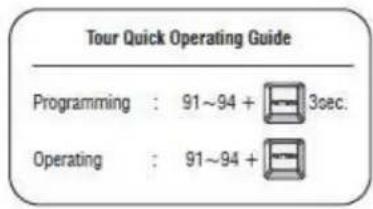
Tour: Up to 8 programmable Tours consisting of presets with individual dwell time.
Scan: Repeatedly pan & tilt operating between two positions. (Max.8)
Pattern: Up to 4 programmable Patterns memorizing the PTZ movement.
Privacy: Up to 8 programmable Privacy masking.
Alarm: Move the camera to programmed Preset position with Alarm trigger.(Max.2)
Area: Up to 16 programmable Area display sets.
WDR (Wide Dynamic Range)
The Camera delivers clear, high quality pictures even in backlight, by increasing exposure in dark areas while decreasing it in bright areas a corrected image with clear details results.
Variable Speed Pan/Tilt Control
In manual mode, sophisticated operating is possible at zoom in state by speed correcting function.
Eco-Friendly Green Energy Product
Minimize power consumption and save the earth by utilizing the VS-WM202 all-in-one camera system.
4. SETTINGS & INSTALLATION
4.1 Unpacking
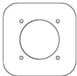
Guiding sticker for installation
natural_image
Simple geometric diagram with a circle and four corner dots inside a rounded square (no text or symbols)Manual

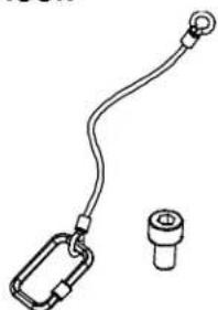
Detaching Hook
natural_image
Simple line drawing of a cable with a loop and a separate cylindrical component (no text or symbols)M8 X10 bolts
4PIN Communication Terminal
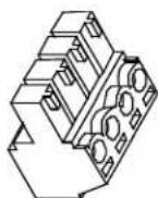
Accessories
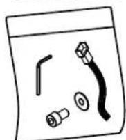
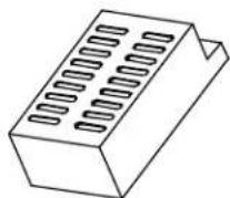
Switched-Mode Power Supply
L-wrench, alarm cable
M8 wrench-bolt, M8 nut
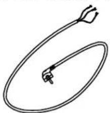
MAIN CABLE
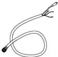
natural_image
Simple line drawing of a coiled tube or cable with two connectors (no text or symbols)POWER CABLE
natural_image
Simple line drawing of a medical or laboratory device with an oval body and pointed tip (no text or symbols)4.2 DIP Switch Settings
Before starting up the camera, set the protocol, camera address and details with dip-switches referring to the following.
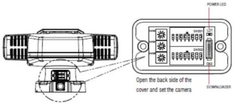
Camera ID (ADDRESS)
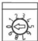
S/W303
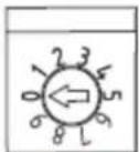
S/W304
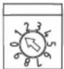
S/W305
S/W3: 100 digit of ID
S/W4: 10 digit of ID
S/W5 : 1 digit of ID
Ex) S/W 3=0, S/W 4=0, S/W 5=1
Address=001
Each camera must have a unique address (ID). Identical ID's on the same line may damage the control circuit caused by an electric short.
SW 302

PROTOCOL
| 1 | 2 | 3 | 4 | PROTOCOL |
| 0 | 0 | 0 | 0 | EZP |
| 0 | 0 | 0 | 1 | PELCO D V1.0 |
| 0 | 0 | 1 | 0 | PELCO P |
| 0 | 0 | 1 | 1 | WTX |
| 0 | 1 | 0 | 0 | PELCO D V5.0 |
| 0 | 1 | 0 | 1 | OCP |
| 0 | 1 | 1 | 0 | yujin |
| 0 | 1 | 1 | 1 | NC |
| 1 | 0 | 0 | 0 | sj 1000 |
SW 301 RS485 LOOP (TERMINATION)

SW 301
| 2 | 3 | |
| 0 | 0 | NC |
| 0 | 1 | NC |
SW 301 LED TYPE

| 4 | LED TYPE |
| 0 | IR |
| 1 | WHITE |
SW 301 SW 302

| SW 301 | SW 302 | |||
| 5 | 6 | Output Format | 8 | Video Mode |
| 0 | 0 | 1920 x 1080p 30 | OFF | NTSC |
| 0 | 1 | 1920 x 1080i 60 | ||
| 1 | 1 | 1920 x 1080i 59.94 | ||
| 1 | 0 | 1280 x 720p 60 | ||
| 0 | 0 | 1920 x 1080p 25 | ON | PAL |
| 0 | 1 | 1920 x 1080i 50 | ||
| 1 | 0 | 1280 x 720p 50 | ||
| 1 | 1 | Reserved | - | - |
SW 302

BAUDRATE
| 5 | 6 | 7 | BAUDRATE |
| 0 | 0 | 0 | 2400 |
| 0 | 0 | 1 | 4800 |
| 0 | 1 | 0 | 9600 |
| 0 | 1 | 1 | 19200 |
| 1 | 0 | 0 | 38400 |
| 1 | 0 | 1 | 57600 |
| 1 | 1 | 0 | NC |
| 1 | 1 | 1 | NC |
SW 301 CAMERA SELECTION

| 7 | 8 | CAM TYPE |
| 0 | 0 | EH-6300 |
| 0 | 1 | MM-202 |
| 1 | 0 | NC |
| 1 | 1 | NC |
4.3 Cable Connection
4. 3. 1 Basic Diagram of Cable Connection
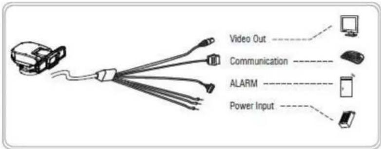
4. 3. 2 Video Output Connection 2
Connect the video out (BNC) connector to the monitor or HD SDI video input of DVR.
4. 3. 3 RS-485 / RS-422 Communication Connection
It can be remotely controlled by an external device or control system, such as a control keyboard or DVR, using RS-485 half-duplex, RS-422 duplex or simplex serial communication signals. After inserting 4pin communication terminal of accessory package to green port of main cable, connect marked RX+, RX- to TX+ and TX- of the RS-485 control system. If control system is RS-422, connect TX+, TX- of controller to RX+ and RX- of the camera. And also connect the TX+, TX- of camera to RX+, RX- of the control device respectively. Total length of the cable for communication should not exceed 1.2Km.
4. 3. 4 Alarm Connections
It can operate specific motion receiving external Alarm Device (Sensor) signal (Max 2 Alarm.) Connect the alarm cable to external Alarm Device referring to below, directions.
- Green color line: Ground / Brown & Orange color lines: Alarm 1 & 2.
4. 3. 5 Power Connections
- After connecting above 3 connections (Video/Communication/Alarm), Connect the power cable last.
- There are 3 lines: Red, Black, Gray. Connect red and black lines to + and - of power. And connect the gray line for Ground.
- Connect the power of DC 24V, 10A to this camera.
- Use certified Class 2 power supply transformers only.
4. 4 Installation
- The following steps of installation and connection work should only be done by qualified service personnel or system installers and should conform to all local codes.
- Be sure to switch the camera off before installation is completed.
- Do not install the camera near the air outlet of an air conditioner.
- Before installation, set camera system with Dip-switches on the 7\~8 pages.
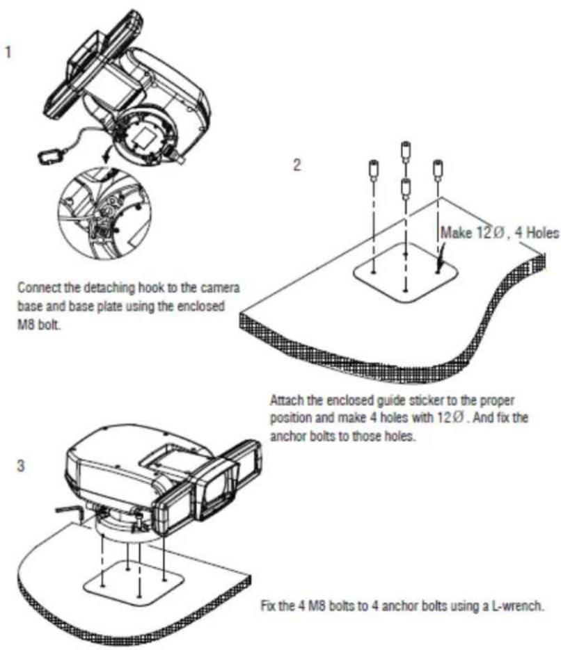
4. 5 Basic Configuration
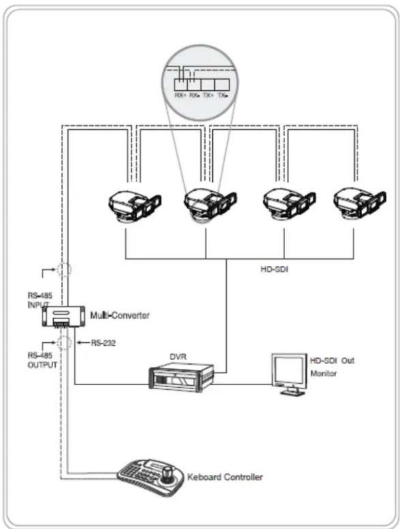
flowchart
graph TD
    A["Keboard Controller"] --> B["Multi-Converter"]
    B --> C["RS-232"]
    C --> D["DVR"]
    D --> E["HD-SDI Monitor"]
    E --> F["RD+ RX+ TX+ TXe"]
    F --> G["Device 1"]
    F --> H["Device 2"]
    F --> I["Device 3"]
    F --> J["Device 4"]
    G --> K["RS-485 INPUT"]
    H --> L["RS-485 OUTPUT"]
    I --> M["RS-485 INPUT"]
    J --> N["RS-485 OUTPUT"]
5. MAIN SETUP MENU
5.1 Initialize
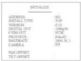
When the device is powered on, you can check the address, version, protocol and video setting values.
5.2 Motion Setting
5.2.1 Preset
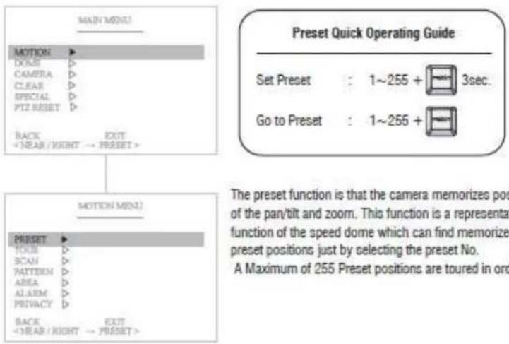
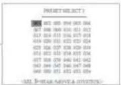
(1) Select the Preset number
P01 : Defined Preset number / 01 : Undefined Preset number

(2) Set the Preset Label
It's available to set the desired label, displayed on the executing screen of Preset.

After the label is set, push the NEAR button to exit.
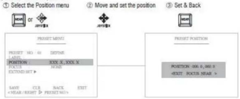
(3) Define the Preset position
flowchart
graph TD
    A["① Select the Position menu"] --> B["OR"]
    B --> C["2017.1"]
    C --> D["2017.2"]
    D --> E["3 Set & Back"]
    E --> F["HEAD"]
    G["POSITION: XXX X, XXX X\nFOCUS: FRONT\nEXTEND SET ▶"] --> H["RESET MENU"]
    I["SAVE CLR BACK EXIT\n<NEAR/BRIGHT > PRESET NO."] --> H
    J["POSITION: 000.0, 000.0\n<EXIT FOCUS NEAR >"] --> K["RESET POSITION"]
(4) Select the focus mode for Preset

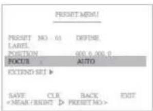
On focus menu, there are 4 modes: None, Auto, Manual, On Shot. It allows detailed settings for the preset.
(5) EXTEND SET
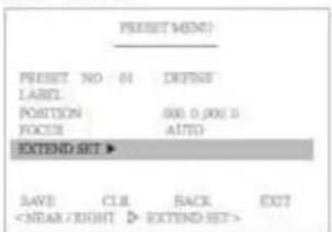
Set the additional preset functions.
AE MODE
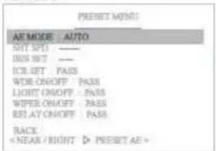
Select AUTO, SHUTTER, IRIS and PASS MODE.

SHUTTER SPD
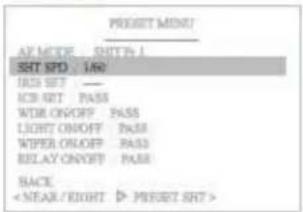
Set shutter speed in the AE MODE.

IRIS SETTING
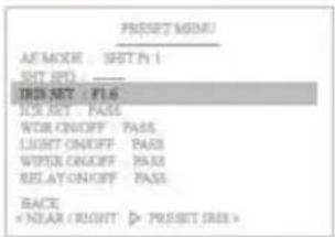
Set IRIS value in the AE MODE.


ICR SETTING
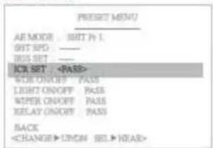
Select PASS, DAY, NIGHT and AUTO in the IR LED.


WDR ON/OFF
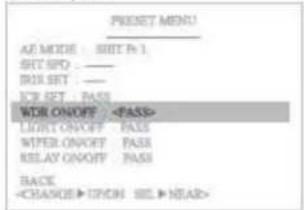
Set WDR function.
Select PASS, ON and OFF.


LIGHT ON/OFF
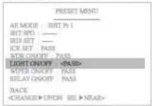
Select PASS, ON and OFF.
: Select NIGHT in the ICR MODE and set ON.


WIPER ON/OFF
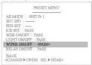
Select PASS, ON and OFF.


RELAY ON/OFF
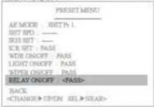
Select PASS, ON and OFF.
Select :


Set ON

Set OFF:

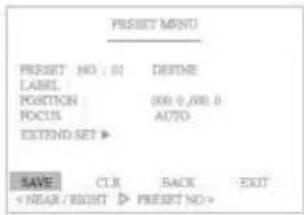
(6) "Save" above setting Pattern data to the memory.
(7) "CLR" means above setting Pattern data will not be saved and be cleared.
(8) "BACK" means it goes back to the previous menu :Motion.
(9) "EXIT" means it goes out of MENU.
5.2.2 Tour
flowchart
graph TD
    A["MAD/MEEN"] --> B["MOTION"]
    B --> C["DOCK"]
    B --> D["CAMERA"]
    B --> E["CLEAR"]
    B --> F["SPECIAL"]
    B --> G["PITZ RESET"]
    B --> H["BACK"]
    H --> I["< NEAR / RIGHT → PRESET>"]
    J["MOTION MENU"] --> K["PRESET"]
    K --> L["TOUR"]
    L --> M["SCAN"]
    L --> N["BATTERM"]
    L --> O["AREA"]
    L --> P["ALARM"]
    L --> Q["PRIVACY"]
    L --> R["BACK"]
    R --> S["< NEAR / RIGHT → TOUR>"]
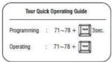
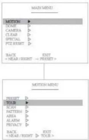
The Tour function consists of several presets run by turn. It is also adjusts the moving speed (1\~63 step) and dwell time (1\~99secs). Maximum of 8 Tour functions are toured in order. (* 1 Tour can be set for 15 presets.)
(1) Select the Tour number
T01 : Defined Tour number / 01 : Undefined Tour number
Move :

Select :

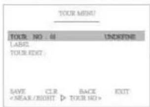
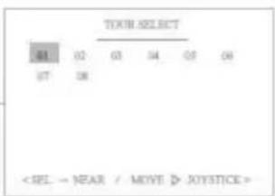
(2) Set the Tour Label
Move:

Select :

C
Delete


It's available to set the desired label, displayed on the executing screen of Tour.
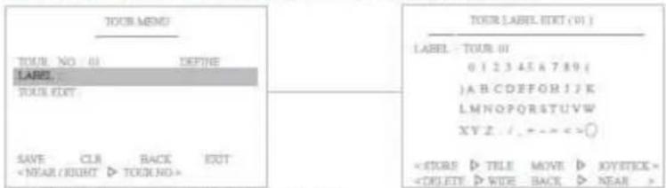
After the label is set, push the NEAR button to exit.
(3) Define the Preset position
① Move to the set-up window


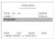
② Move and set the position

③ Set & Back

| NO. | PROJECT | ORDER | DESCRIPTION |
| 81 | ● 61 | 61 | 01 |
| 82 | - 32 | 41 | 01 |
| 83 | - 37 | 32 | XX |
| 84 | - 32 | 32 | XX |
| 85 | - 32 | 32 | XX |
| 86 | - 32 | 32 | XX |
| 87 | - 32 | 32 | XX |
| 88 | - 32 | 32 | XX |
| × 100, B = 99.66 | PROJECT = 100% | ||
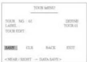
(4) "Save" above setting Pattern data to the memory.
(5) "CLR" means above setting Pattern data will not be saved and be cleared.
(6) "BACK" means it goes back to the previous menu: Motion.
(7) "EXIT" means it goes out of MENU.
5.2.3 Scan
flowchart
graph TD
    A["MAIN MENU"] --> B["MOTION"]
    B --> C["DONE"]
    B --> D["CAMERA"]
    B --> E["CLEAR"]
    B --> F["SPECIAL"]
    B --> G["PTZ RESET"]
    B --> H["BACK"]
    H --> I["<YEAR <RIGHT >"]
    B --> J["EXIT"]
    J --> K["PRESSET"]
    L["MOTION MENU"] --> M["PRESSET"]
    L --> N["TOUR"]
    L --> O["SCAN"]
    O --> P["PACTION"]
    O --> Q["AREA"]
    O --> R["ALARM"]
    O --> S["PRIVACY"]
    O --> T["BACK"]
    T --> U["<NEAR <RIGHT >"]
    O --> V["EXIT"]
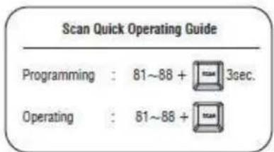
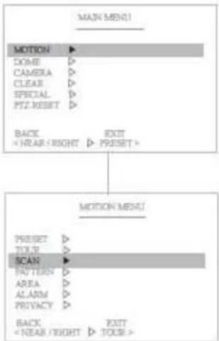
The Scan function means that the camera keeps panning between two programmed pan positions. It is also adjusts the moving speed(1\~63 step). Maximum 8 Scan functions are toured in order.
(1) Select the Scan number
S01 : Defined Scan number / 01 : Undefined Scan number
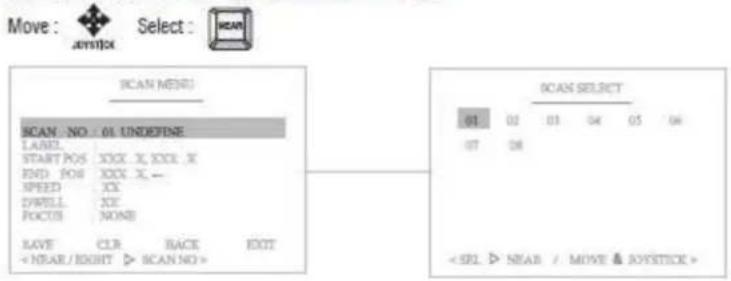
(2) Set the Scan Label

It's available to set the desired label, displayed on the executing screen of Scan.
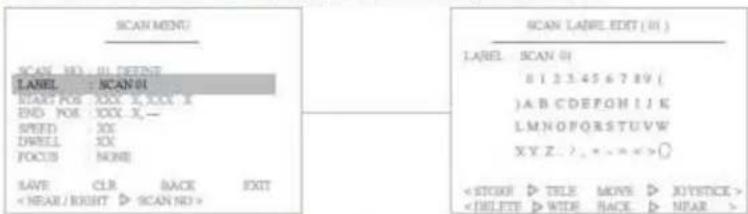
After the label is set, push NEAR button to go out.
(3) Define the Start pan position
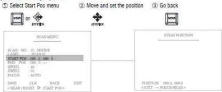
(4) Define the End pan position
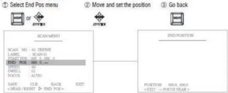
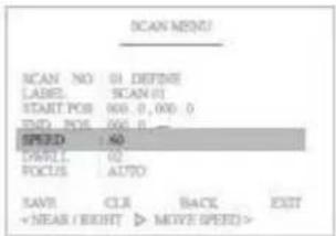
(5) Set the Scan speed
Increase :


Decrease :


It adjusts the moving speed from 1\~63 steps.
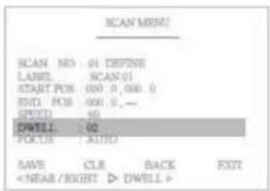
(6) Set the Dwell Time
Increase :


Decrease :


Dwell time means the time that the camera stay at the start & end pan positions. It's adjustable from 1\~99 seconds.
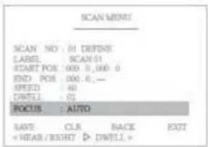
(7) Set the Focus
Focus can be set Auto or Manual.
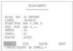
(5) "Save" above setting Pattern data to the memory.
(6) "CLR" means above setting Pattern data will not be saved and be cleared.
(7) "BACK" means it goes back to the previous menu: Motion.
(8) "EXIT" means it goes out of MENU.
5.2.4 Pattern
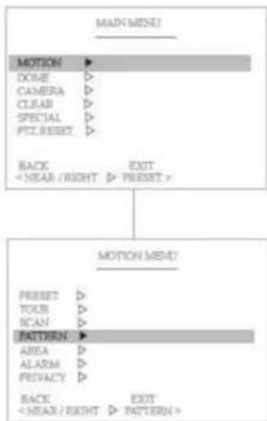
flowchart
graph TD
    A["MAIN MENU"] --> B["MOTION"]
    B --> C["DOCE"]
    B --> D["CAMERA"]
    B --> E["CLEAR"]
    B --> F["SPECIAL"]
    B --> G["PIT, RESET"]
    B --> H["BACK"]
    H --> I["<NEAR / RIGHT ▷ PRESET>"]
    I --> J["MOTION MENT"]
    J --> K["PRESET"]
    J --> L["TOUR"]
    J --> M["SCAN"]
    J --> N["PATTERN"]
    N --> O["AREA"]
    N --> P["ALARM"]
    N --> Q["PREVACY"]
    N --> R["BACK"]
    R --> S["<NEAR / RIGHT ▷ PATTERN>"]
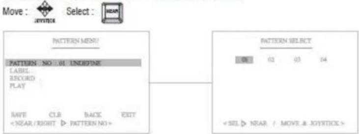
The Pattern function memorizes User's random moving path and zoom ratio. Total recording time limit is 90secs and maximum 4 Pattern functions are toured in order.
(1) Select the Pattern number
PAT01 : Defined Pattern number / 01 : Undefined Pattern number
(2) Set the Pattern Label

It's available to set the desired label, displayed on the executing screen of Pattern.
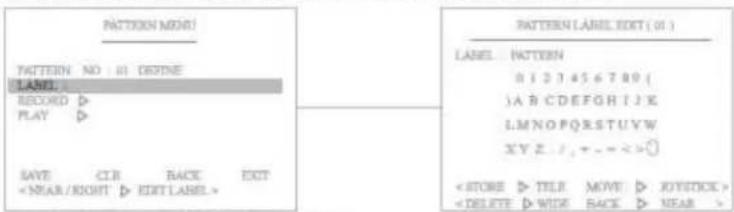
After the label set, push NEAR button to go out.
(3) Record and Save the User's random Pattern data
① Select the "Record" Menu ② Move and record the pattern ③ Set & Back
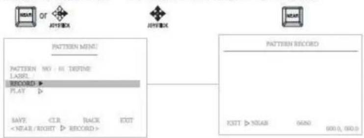
flowchart
graph TD
    A["Pattern Menu"] --> B["Pattern NO: M DEFINE LABEL"]
    B --> C["RECORD ▶"]
    C --> D["PLAY ▶"]
    D --> E["SAVE <CLR BACK EXIT"]
    E --> F["<NEAR/RIGHT ▶ RECORD >"]
    G["Pattern Record"] --> H["EXIT ▷ NEAR 0690 000.0, 000.0"]
(4) Play back the recorded Pattern data
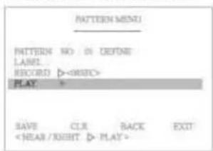
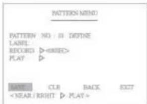
(5) "Save" above setting Pattern data to the memory.
(6) "CLR" means above setting Pattern data will not be saved and be cleared.
(7) "BACK" means it goes back to the previous menu: Motion.
(8) "EXIT" means it goes out of MENU.
5.2.5 Area
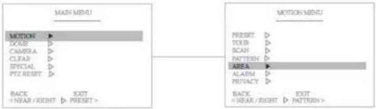
The Area function means that it displays the Area name between two programmed pan positions. Maximun 16 Area functions are toured in order.
(1) Select the Area number
AR 01 : Defined Area number / 01 : Undefined Area number
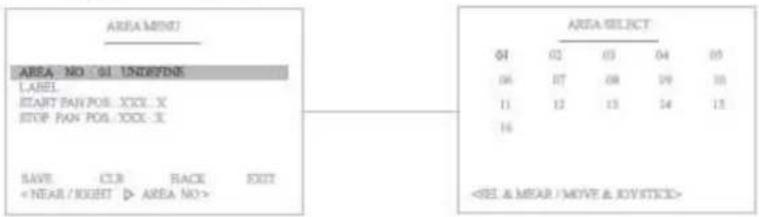
(2) Set the Area Label

It's available to set the desired label, displayed on the executing screen of Area.
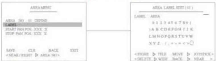
After the label set, push NEAR button to go out.
(3) Define the Start pan position
① Select the "Start Pan Pos" menu ② Move and set the position ③ Set & Back
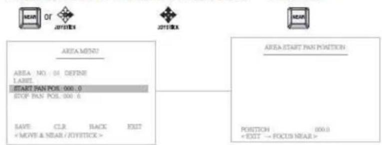
※ Camera will move to clockwise direction only when START setting.
(4) Define the Stop pan position
① Select the "Start Pan Pos" Menu② Move and set the position
③ Set & Back
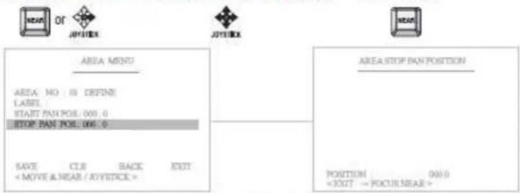
** Only pan position is adjustable, because tilt position is fixed when "Start Pan Position" is set.
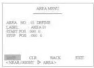
(5) "Save" above setting Area data to the memory.
(6) "CLR" means above setting Area data will not be saved and be cleared.
(7) "BACK" means it goes back to the previous menu: Motion.
(8) "EXIT" means it goes out of MENU
5.2.6 Alarm
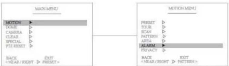
The Alarm function means that the camera moves to the programmed Preset position by the Alarm trigger Maximum 2 Alarm functions are toured in order.
(1) Select the Alarm number
Alarm 01 : Defined Alarm number / 01 : Undefined Alarm number
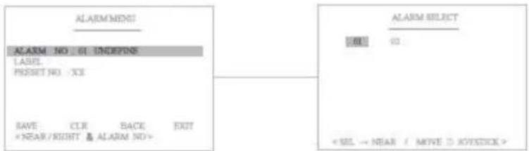
(2) Set the Alarm Label

It's available to set the desired label, displayed on the executing screen of Alarm.
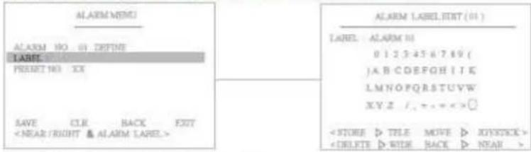
After the label is set, push the NEAR button to exit.
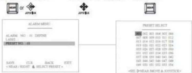
(3) Define the Preset position with Alarm trigger
① Select the "Preset No" ② Move and set the position ③ Set & Back
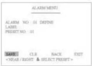
(4) "Save" above setting Alarm data to the memory.
(5) "CLR" means above setting Alarm data will not be saved and be cleared.
(6) "BACK" means it goes back to the previous menu :Motion.
(7) "EXIT" means it goes out of MENU
5. 2. 7 Privacy Zone Masking
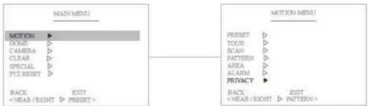
The Privacy Zone Masking function means that it sets the blocking territories to prevent camera functions for the privacy of personal reasons. Maximum of 8 Privacy Zone Masking functions are toured in order.
(1) Select the Privacy Zone number
Privacy 01 : Defined Alarm number / 01 : Undefined Alarm number
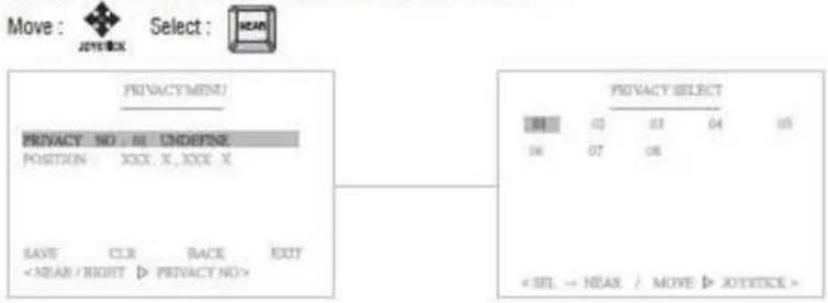
(2) Set the Privacy Zone Position

It's available to set the desired position and size of the blocking territories freely.
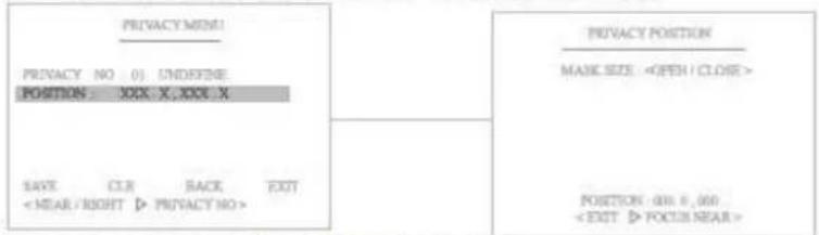
After the Privacy Zone is set, push the NEAR button to go out.
(3) "Save" above settings of Privacy Zone data to the memory.
(4) "CLR" means above setting of Privacy Zone data will not be saved and be cleared.
(5) "BACK" means it goes back to the previous menu :Motion.
(6) "EXIT" means it goes out of MENU.
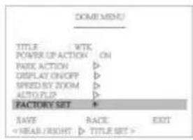
5.3 Dome Setting
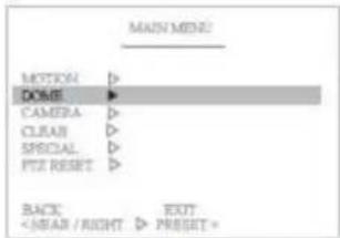
Pan, Tilt, Zoom motion is adjustable in the "Dome Setting" Menu.
5. 3. 1 Set the Dome Camera Title

It's available to set the desired camera title.
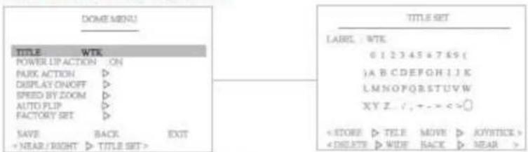
After the label is set, push NEAR button to exit.
5.3.2 Set the Power Up Action
When this function is ON, the camera memorizes the latest action and restores, it from sudden power failure.

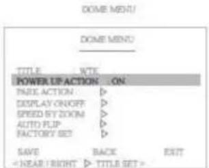
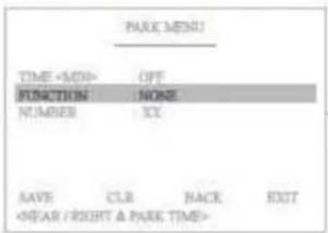
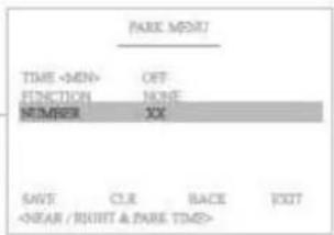
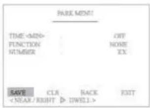
5.3.2 Park Action
This function enables to locate the camera to specific position automatically if operator doesn't operate the controller for a while.
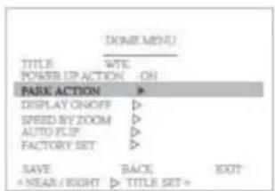
(1) Set the park Time (OFF, 01\~60 min)
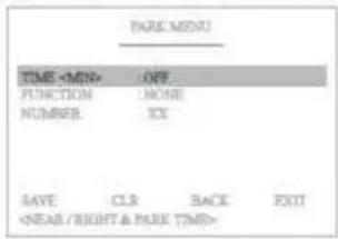
(2) Select the function which will be back after the above set time.
(3) Select the appointed function's Number
(4) "Save" above setting data to the memory.
(5) "CLR" means above setting Pattern data will not be saved and be cleared.
(6) "BACK" means it goes back to the previous menu.
(7) "EXIT" means it goes out of the MENU
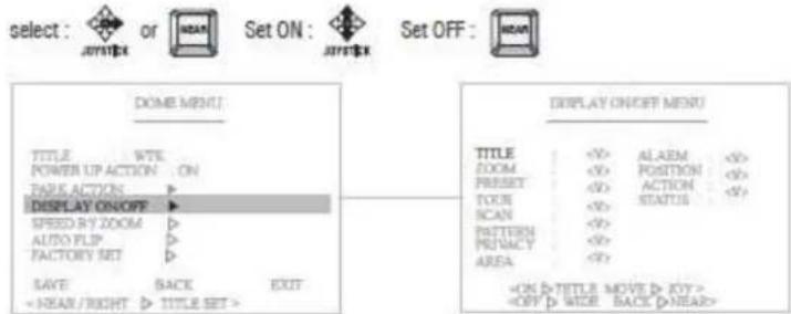
5.3.4 Display ON/OFF Set
You can select the OSD ON to shown on the screen or clear by selecting OFF in this function.
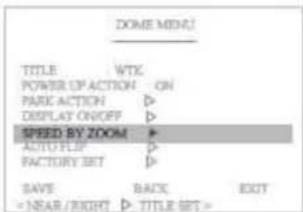
5. 3. 5 Speed by Zoom ON/OFF Set
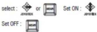
When this function is ON, the pan/tilt speed is inversely adjusted to the zoom ratio.
5. 3. 6 Auto Flip ON/OFF Set
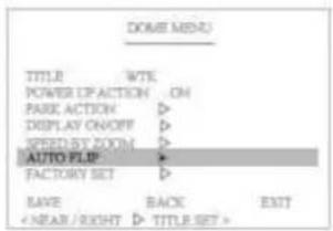
You can observe the moving object without reversing of the screen, by using this AUTO FLIP function.
ON: If this function is set to ON, camera will be automatically flipped in tilt 90°
OFF: If this function is set to OFF, tilt movement range is 0\~90°
select :


Set ON

Set OFF:

5.3.7 Factory Set
Restore setting values to the factory default.

All existing setting value will be erased.
5.4 Camera Settings
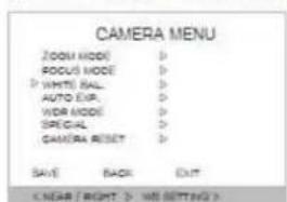
5. 4. 1 CAMERA MENU (EH-6300)
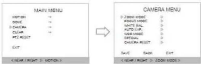
CAMERA MENU
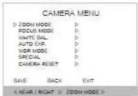
- Functions can be set-up using the Camera menu.
In this menu, user can set the zoom, focus, white balance, auto exposure...etc functions.
① ZOOM MODE
Decide using of digital zoom function and select zoom speed.
* ZOOM SPD : 1 \~ 7 steps, USER(standard)
* D-ZOOM : ON / OFF
-ZOOM SPD
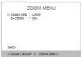
ZOOM SPO : Select from 1 sept to 7 steps,
USER (Standard speed)
Select :


Set ON

Set OFF:

-D-ZOOM
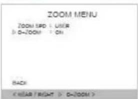
Decide using of digital zoom function.
D-ZOOM: ON/OFF
Select:


Set ON

Set OFF:

② FOCUS MODE
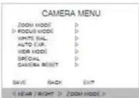
In Focus menu, you can set up the focus speed, focus mode, near limit, AF mode and sensitivity.
- FOCUS SPD
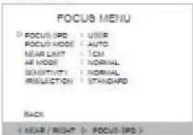
Set the speed for camera focusing.
Select

or

Set ON

Set OFF

- FOCUS MODE
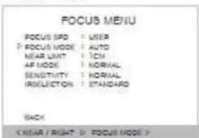
AUTO: The camera adjusts the focus automatically while monitoring the screen continuously in the auto mode. In the auto focusing mode, zoom key operation is not recognized as the input of the focus key.
Manual: In the manual mode, users can adjust the camera focus manually.
One Push: It will be focused in about 5 seconds after zooming, panning, and return to MANUAL mode automatically. This is for focusing accurately after zooming.
Infinity: infinity focus is the state where a lens forms an image of an object an infinite distance away. This corresponds to the point of focus for parallel rays.
Select :

or

Set ON

Set OFF

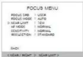
- NEAR LIMIT
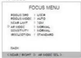
- AF MODE
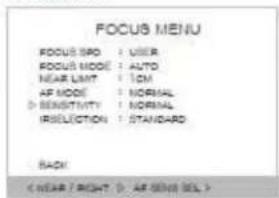
-SENSITIVITY
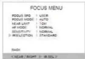
- IR SELECTION
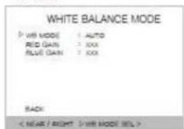
③ WHITE BALANCE Set the white balance of camera.
- WB MODE
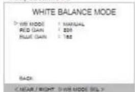
- RED, BLUE MODE
Infinity focus is the state where a lens forms an image of an object an infinite distance away. This corresponds to the point of focus for parallel rays. (Over Infinity\~1.0CM)

Set the AUTO FOCUS MODE position

Set the sensitivity of focus.

Correct the IR conversion data.

White balance setting is a function revising color temperature to resolve the problem that screen's colors change by the color temperature's difference according to time. RED GAIN: Adjust red color level from 0\~255. BLUE GAIN: Adjust blue color level from 0\~255.

WB MODE: Set the color depend on white balacne. WB MODE : Select AUTO, INDOOR, OUTDOOR ONEPUSH, ATW or MANUAL.

Adjust color level (RED, BLUE: 001\~255) Standard level: RED -> 208 BLUE->162

④ AUTO EXPO
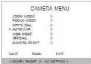
AE setting is a function adjusting shutter speed according to subject's brightness to get standard amount of exposed light.
AE MODE: Select AUTO, MANUAL, SHUTTER, IRIS or BRIGHT.
EXPOSURE: 10.5dB \~ -10.5dB (Standard 0dB)
SLOW SHUTTER: Select AUTO, MENUAL
SHUTTER: Set the shutter speed.
IRIS LEVEL: If you set IRIS in AE mode, you can control the level value (CLOSE \~F1.6)
BRIGHT LEVEL: If you set BRIGHT in AE mode, you can control level value (00\~31)
Gain: Control the brightness (-3dB \~ 28dB)
- AE MODE
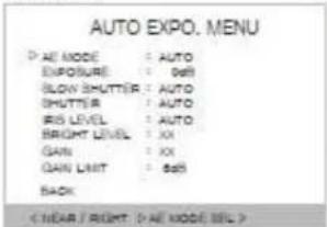
Select AUTO, MANUAL, SHUTTER, IRIS or BRIGHT.

- EXPO MODE
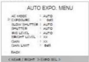
Set the exposure.

- SLOW SHUTTER
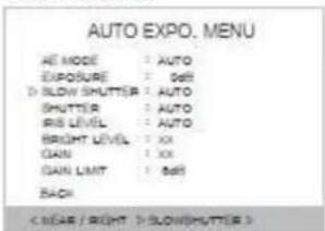
Select AUTO or MANUAL

- SHUTTER
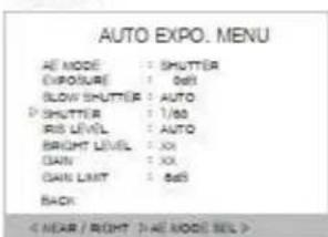
If you set SHUTTER in the AE MODE, you can control shutter speed.
(1/50, 1/80, 1/120, 1/150, 1/250, 1/500, 1/1000, 1/1500,
1/2000, 1/5000, 1/10000, 1/20000, 1/50000, 1/100000)

- IRIS LEVEL
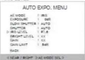
If you set IRIS in the AE MODE, you can set the IRIS level from 00 to 17.

- BRIGHT LEVEL
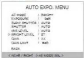
If you set BRIGHT in AE mode, you can control level value.
Select


Set ON

Set OFF:

- GAIN
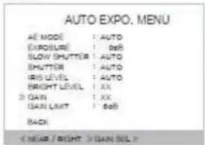
If you set MEMUAL in AE mode, you can control Gain.
Select :


Set ON

Set OFF:

- GAIN LIMIT
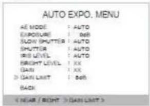
Change the GAIN LIMIT. (0\~30dB) -changed by 2dB
Select :


Set ON

Set OFF:

⑤ WDR MODE
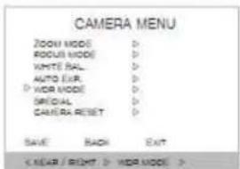
Select WDR(Wide Dynamic Range)

- WDR MODE
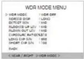
Select ON or OFF and set the LEVEL and the LIMIT value. (OFF, LEV1 \~ LEV7)

- SCREEN DISP
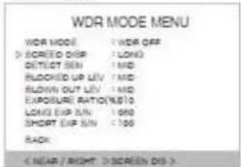
Select WDR changing time.(LONG.SHORT)

- DETECTION SENSITIVITY
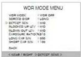
Change the WDR level

- BLOCKED UP LEVEL
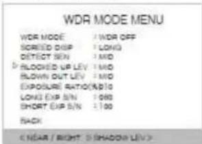
Select blocked up level (LOW.MID.HIGH)

- BLOWN-OUT LEVEL
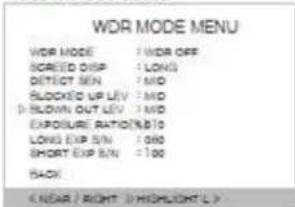
Select blown-out level

- EXPOSURE RATIO
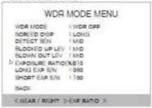
Select exposure ratio

- LONG EXPOSURE
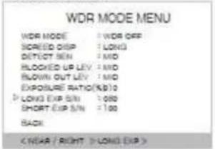
Select long exposure

- SHORT EXPOSURE
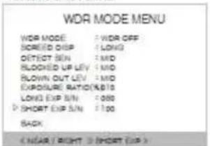
Select short exposure

⑥ SPECIAL
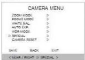
In the Special menu, it's available to set special function of the camera

- ENHANCE
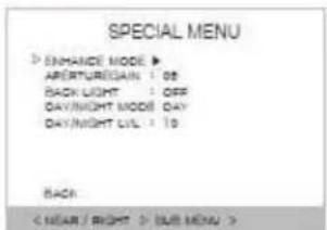
- Functions can be set-up using the Camera menu. In this menu, user can set the zoom, focus, white balance, auto exposure...etc functions.
① ZOOM MODE
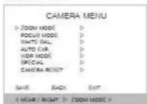
Decide using of digital zoom function and select zoom speed.
• ZOOM SPD : 1 \~ 7 steps, USER(standard)
* D-ZOOM : ON / OFF
-ZOOM SPD
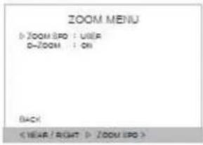
ZOOM SPD: Select from 1sept to 7 steps, USER (Standard speed)
Decide using of digital zoom function. D-ZOOM: ON/ OFF
In Focus menu, you can set up the focus speed, focus mode, near limit, AF mode and sensitivity.
- FOCUS SPD
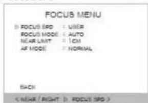
Set the speed for camera focusing.
AUTO: The camera adjusts the focus automatically while monitoring the screen continuously in the auto mode. In the auto focusing mode, zoom key operation is not recognized as the input of the focus key.
Manual: In the manual mode, users can adjust the camera focus manually.
One Push: It will be focused in about 5 seconds after zooming, panning, and return to MANUAL mode automatically. This is for focusing accurately after zooming.
Infinity: infinity focus is the state where a lens forms an image of an object an infinite distance away. This corresponds to the point of focus for parallel rays.
Infinity focus is the state where a lens forms an image of an object an infinite distance away. This corresponds to the point of focus for parallel rays.
(Over Infinity\~1.0CM)
Select: or Set ON: Set OFF:
- AF MODE
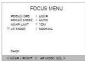
Set the AUTO FOCUS MODE position
Select


Set ON

Set OFF:

③ WHITE BALANCE Set the white balance of camera.
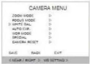
White balance setting is a function revising color temperature to resolve the problem that screen's colors change by the color temperature's difference according to time. RED GAIN: Adjust red color level from 0\~20. BLUE GAIN: Adjust blue color level from 0\~20.
Select :


Set ON

Set OFF:

- WB MODE
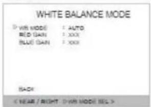
WB MODE: Set the color depend on white balacne. WB MODE : Select AUTO, INDOOR, OUTDOOR ONEPUSH, ATW or MANUAL.
Select :


Set ON

Set OFF:

- RED, BLUE MODE
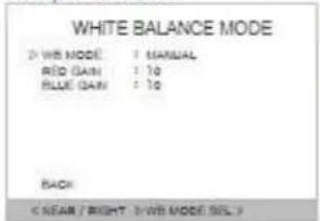
Adjust color leveri (RED, BLUE: 01\~20) Standard level: RED -> 10 BLUE->110
Select :


Set ON

Set OFF:

④ AUTO EXPO
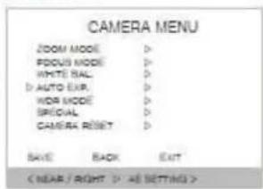
AE setting is a function adjusting shutter speed according to subject's brightness to get standard amount of exposed light.
AE MODE: Select AUTO, MANUAL, SHUTTER, IRIS. EXPOSURE : 00 \~ 20 (Standard 00)
SLOW SHUTTER: Select AUTO, MANUAL
SHUTTER: If you set SHUTTER in AE mode, you can control the level value
IRIS LEVEL: If you set IRIS in AE mode, you can control the level value (00\~20)
DSS LEVEL: Control digital show shutter speed.
- AE MODE
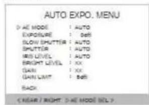
Select AUTO, MANUAL, SHUTTER, IRIS or BRIGHT.
Select


Set ON

Set OFF :

- EXPO MODE
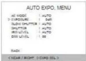
Set the exposure.(00 \~20)


Set ON

Set OFF

- SLOW SHUTTER
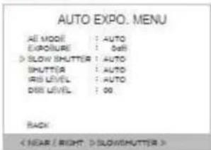
Select AUTO or MANUAL.


Set ON

Set OFF

- SHUTTER
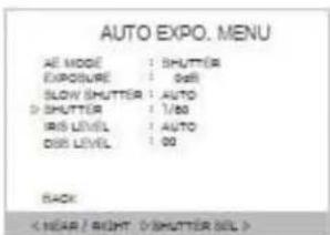
If you set SHUTTER in the AE MODE, you can control shutter speed.
(1/30, 1/60, 1/120, 1/240, 1/500, 1/1000, 1/2000, 1/4000,
1/8000, 1/16000, 1/30000, 1/60000, X4, X3, X2)


Set ON

Set OFF

- IRIS LEVEL
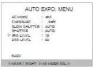
If you set IRIS in the AE MODE, you can set the IRIS level from 00 to 20
Select :

or

Set ON

Set OFF:

- DSS LEVEL
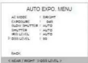
Digital Slow Shutter: Control digital show shutter speed.
(00,01,02,03설정)
Select :

or

Set ON

Set OFF:

⑤ WDR MODE
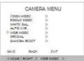
Set WDR function
WDR(Wide Dynamic Range)
- WDR MODE
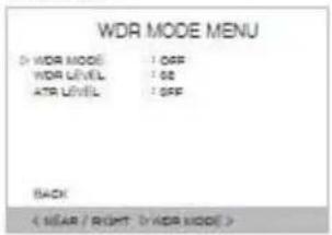
Select ON or OFF
Select


Set ON

Set OFF:

- WDR LEVEL
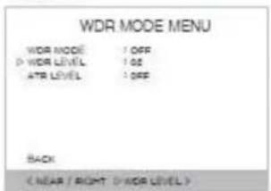
Select from 00 to 03.
-


Set ON

Set OFF:

- ATR LEVEL
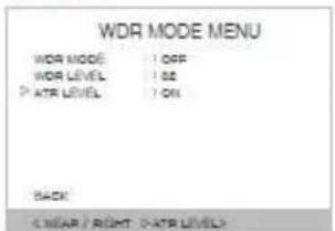
Select ON or OFF
Select


Set ON

Set OFF :

⑥ SPECIAL
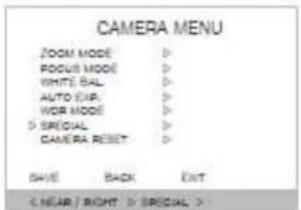
In the Special menu, it's available to set special function of the camera
select :


Set ON

Set OFF:

- ICR MODE
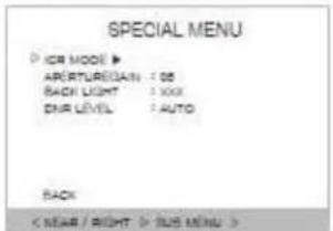
Control DAY & NIGHT function.
- ICR MODE
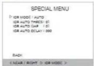
Select AUTO, DAY and NIGHT.
select


Set ON

Set OFF

- ICR AUTO THRESHOLD
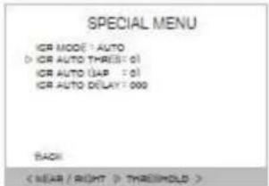
Set the ICR THRESHOLD
select :

。

Set ON

Set OFF :

- ICR AUTO GAP
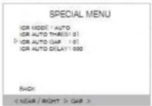
Select the ICR level.
select:

or

Set ON

Set OFF:

- ICR AUTO DELAY
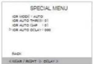
Set ICR auto delay.
select :

or

Set ON

Set OFF :

- APERTURE GAIN
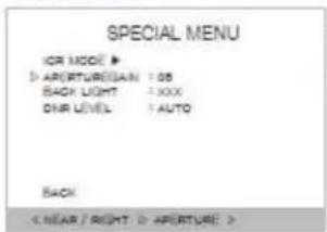
APERTURE GAIN: Select aperture gain
select :

or

Set ON

Set OFF:

- BACK LIGHT
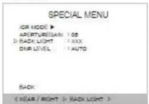
Select ON/OFF in the BACK LIGHT function.
select :

0

Set ON

Set OFF:

- DNR LEVEL
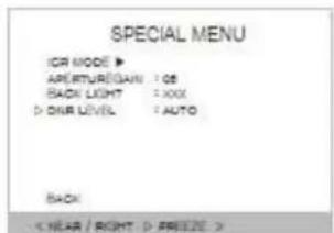
Select the DNR level from AUTO, LEV1, LEV2, LEV3 and OFF.
select

0

Set ON

Set OFF :

⑦ CAMERA RESET
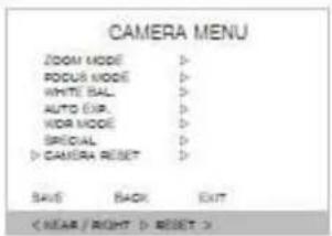
Make initialize the setting value which is set in CAMERA MENU.

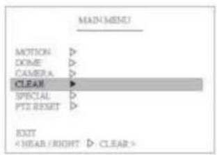
5.5 Clear Settings
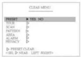
Clears the PTZ position and function value. With this function the camera keeps the accuracy of the PTZ position value.
5.6 Special Settings
In the PIP menu, it's available to set the details for PIP function.
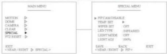
- PIP CAM DISABLE
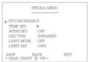
- PIP is not supported. (Support ANALOG product only)
- TEMP SETTING
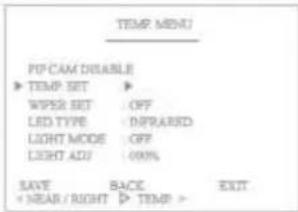
* Set the operating temperature of Fan&Heater in the camera. It shows you the current temperature and you can also set the value manually. The compulsory Fan & Heater operation is a useful function to remove humidity. (Select the operating time of Heater from 10 to 60 min.)
-HEATER ON
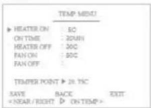
- Set the operating temperature of the heater.
- ON TIME
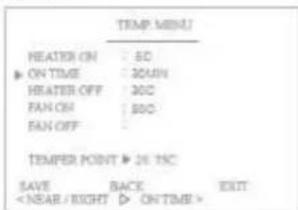
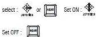
- Set the operating time of the heater.
-HEATER OFF
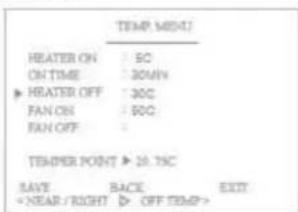
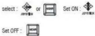
- Set the temperature of heater OFF.
- FAN ON
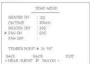
* Set the operating temperature of the fan.
- FAN OFF
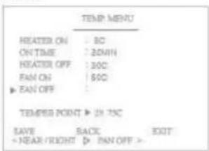
- Set the temperature of Fan OFF.
- WIPER SETTING
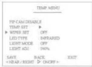
* Set the wiper function of the camera.(ON/OFF)
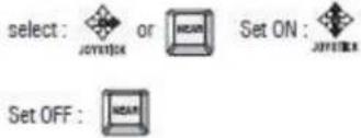
- LED TYPE
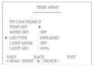
* Select LED type.
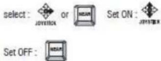
- LIGHT MODE
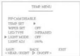
* Select LIGHT MODE. (DAY / NIGHT)
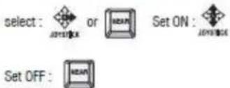
- LIGHT ADJUSTABLE
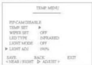
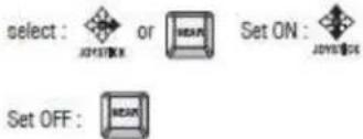
* Adjusts the light value.
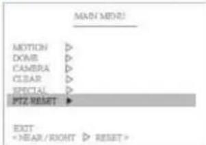
5.7 PTZ Reset
It is a reset function and is useful when you change the dipswitches for address, protocol and baud rate.
5.8 Other Quick Operation Guide
240 + set preset (3sec) = night mode
241 + set preset (3sec)= day mode
242 + set preset (3sec)= auto mode
244 + set preset (3sec)= wiper on
245 + set preset (3sec)= wiper off
246 + set preset (3sec)= heater on
247 + set preset (3sec)= heater off
250 + set preset (3sec) = camera reset
251 + set preset (3sec)= camera refresh
252 + set preset (3sec)= IR on (dip s/w in IR LED mode)
253 + set preset (3sec)= IR off (dip s/w in IR LED led mode)
255 + set preset (3sec)= ptz info
6. SPECIFICATIONS
6.1 Mechanical Specifications
6.1.1 MECHANICAL
| Pan | : 360° Continuous Pan, 0.1° to 90°/sec. |
| Pan Preset Speed | : Max. 150°/sec, ± 0.1° Accuracy |
| Tilt | :-90° to 90° tilt angle |
| Tilt Preset Speed | : Max.150°/sec, ± 0.1° Accuracy |
| Weight | : Approx. 12 Kg/ Packing 15 Kg |
6.1.2 ENVIRONMENTAL
| Construction | : Die-casing Aluminum & “O” Ring sealed: All internal parts are corrosion protected epoxy powder coating |
| Ingress Protection | : IP66 Outdoor Application |
| Color | : Black and Ivory |
| Operating Temp | :-20°C to 50°C (In continuous operation with Fan & Heater) |
| Storage Temp | :-20°C to 60°C |
| Humidity | : 0% to 90% |
6.1.3 FUNCTIONS
| Preset | : 255 points, less than 0.1* accuracy |
| Tour | : 8 programmable |
| Pattern | : 4 patterns |
| Scan | : 8 scans |
| Area | : 4 Area |
| Alarm | : 2 alarms |
| Flip | : Auto Flip On/Off |
| Address | : Up to 255 selectable ID ( setting with Dip-switches) |
| Data Communication Control | : RS-485/ RS-422 |
| Protocol | : Multiple Protocol |
| Baud rate | : 2400, 4800, 9600, 19200, 38400, 57600 bps selectable |
6.1.4 ELECTRICAL
Power
: DC 24V
Power adaptor included
Consumption
: Operating(3A), Max(4.0A, IR light on, Heater on)
Fan & Heater
: 10W/3.4W
6.1.5 CERTIFICATES
CE EMC, FCC CLASS A, RoHS, e-Mark
6.2 Camera Specifications
6.2.1 Zoom Camera
EH-6300
| Imager | 1/3 Type Exmor CMOS Sensor |
| Picture elements | 2000K pixels |
| Lens | 20× zoomF= 4.7 mm (WIDE) to 94.0 mm(TELE), F1.6 to F3.5 |
| Digital zoom | 12× (240× with optical zoom) |
| Angle of view (H) | Approx. 55.4 degrees (WIDE end), approx. 2.9 degrees (TELE end)(1080i mode)Approx. 37.6 degrees (WIDE end), approx. 2.0 degrees (TELE end)(720p mode) |
| Min. working distance | 10 mm (WIDE end), 1000 mm (TELE end) |
| Sync system | Internal |
| Min. illumination(Typical value) | 0.5 lx (1/30 sec, 50%, High Sensitivity mode ON)1.7 lx (1/30 sec, 50%, High Sensitivity mode OFF)ICR-ON Mode0.095 lx (1/30 sec, 50%, High Sensitivity mode ON)0.3 lx (1/30 sec, 50%, High Sensitivity mode OFF) |
| S/N ratio | 50 dB (Weight ON) |
| Wide dynamic range | ON/OFF/AUTO |
| Noise reduction | ON/OFF (level 5 to 1 / OFF, 6 steps) |
| Color Enhancement | ON/OFF |
| Aperture control | 16 steps |
| Preset | 6-POSITIONS |
| Video Output | HD: Analog component (Y/Pb/Pr) Digital (LVDS) Analog SD: VBS |
6. 2. 2 LED Specification
| Infra Red LED | White LED | |
| Light Distance | 200 m(Manual focusing) | |
| LED | Super IR LED 30 EA (OSRAM 870n) with Lens 12° | Super White LED 30EA (OSRAM 870n) with Lens 12° |
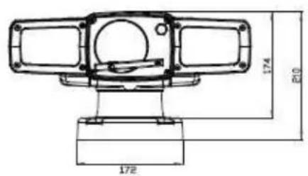
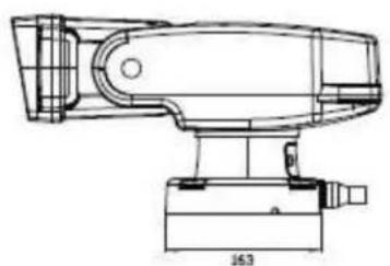
7. DIMENSIONS (mm)
natural_image
Technical line drawing of a mechanical device with no visible text or symbolsMarshall Electronics, Inc.
1910 East Maple Ave. El Segundo, CA 90245
Tel: (800) 800-6608 / (310) 333-0606 • Fax (310) 333-0688
www.LCDRacks.com • sales@lcdracks.com
- Marshall Electronics
- VS-WM202-HDSDI
- Trademarks
- Disclaimer
- Safety Precaution
- TABLE OF CONTENTS
- INFORMATION FOR USER....5
- PRECAUTIONS. 6
- FEATURES. 7
- SETTINGS & INSTALLATION....8
- MAIN SETUP MENU 13
- Dome Setting .....24
- Camera Settings . 27
- SPECIFICATIONS....44
- DIMENSIONS (mm)......47
- INFORMATION FOR USER
- WARNING
- EXPLANATION OF GRAPHICAL SYMBOLS
- FCC COMPLIANCE STATEMENT
- CE COMPLIANCE STATEMENT
- PRECAUTIONS
- FEATURES
- Outdoor Heavy-Duty PTZ Camera
- Unobstructed 360° Rotation and 180° Flip
- Light Function
- Built-In Fan & Heater
- Built-In Wiper System
- True Day & Night (ICR Filter Change)
- Break and Clutch Protected Pan and Tilt
- OSD (On Screen Display)
- Auto-Focus 20X Optical Zoom
- Wide Range Auto Functions
- WDR (Wide Dynamic Range)
- Variable Speed Pan/Tilt Control
- Eco-Friendly Green Energy Product
- SETTINGS & INSTALLATION
- Unpacking
- DIP Switch Settings
- Cable Connection
- 3. 1 Basic Diagram of Cable Connection
- 3. 2 Video Output Connection 2
- 3. 3 RS-485 / RS-422 Communication Connection
- 3. 4 Alarm Connections
- 3. 5 Power Connections
- 4 Installation
- 5 Basic Configuration
- MAIN SETUP MENU
- Initialize
- Motion Setting
- Preset
- RELAY ON/OFF
- Tour
- Set the Tour Label
- Define the Preset position
- Scan
- Pattern
- Area
- Select the Area number
- Set the Area Label
- Define the Start pan position
- Alarm
- 2. 7 Privacy Zone Masking
- Select the Privacy Zone number
- Set the Privacy Zone Position
- Dome Setting
- 3. 1 Set the Dome Camera Title
- Set the Power Up Action
- Park Action
- Display ON/OFF Set
- 3. 5 Speed by Zoom ON/OFF Set
- 3. 6 Auto Flip ON/OFF Set
- Factory Set
- Camera Settings
- 4. 1 CAMERA MENU (EH-6300)
- CAMERA MENU
- EXPOURE : 0dB
- SHUTTER : 1/60
- EXPOSURE RATIO(KB10)
- ① ZOOM MODE
- Clear Settings
- Special Settings
- - TEMP SETTING
- -HEATER ON
- - ON TIME
- -HEATER OFF
- - FAN ON
- - FAN OFF
- PTZ Reset
- Other Quick Operation Guide
- SPECIFICATIONS
- Mechanical Specifications
- MECHANICAL
- ENVIRONMENTAL
- FUNCTIONS
- ELECTRICAL
- CERTIFICATES
- Camera Specifications
- Zoom Camera
- 2. 2 LED Specification
- DIMENSIONS (mm)
- Marshall Electronics, Inc.
Brand : Marshall Electronics
Model : VS-WM202-HDSI
Category : Surveillance Camera