
VPC100 - Office VIEWSONIC - Free user manual and instructions
Find the device manual for free VPC100 VIEWSONIC in PDF.


| Product Type | All-in-One PC |
| Brand | ViewSonic |
| Model | VPC100 |
| Processor | Intel Atom N280 1.66GHz Single Core |
| Operating System | Microsoft Windows XP Home |
| Memory | 1GB DDR2 (max 2GB) |
| Storage | 160GB SATA hard disk |
| Display Size | 19" TFT LCD (18.5" viewable) |
| Display Resolution | 1366 x 768 (native) |
| Webcam | 1.3 Megapixel |
| Keyboard | PS/2 100 keys with hot keys |
| Mouse | PS/2 Optical |
| Audio | Stereo speakers 3W x 2, headphone and microphone jacks |
| LAN | Gigabit Ethernet |
| Wireless LAN | 802.11 b/g |
| Optical Drive | DVD Super Multi (slim tray-in) |
| Card Reader | 4-in-1 (XD/SD/MMC/MS) |
| USB Ports | 4 (2 rear, 2 side) |
| PS/2 Ports | 2 (keyboard and mouse) |
| Power Supply | 65W adapter, 19V DC |
| Dimensions (with stand) | 450 x 432 x 35 mm |
| Weight | 5.3 kg (11.7 lbs) |
| VESA Mount | 100x100mm (holes) |
| Power Consumption | Max 65W |
| Warranty | 1 year parts and labor |
Frequently Asked Questions - VPC100 VIEWSONIC
User questions about VPC100 VIEWSONIC
0 question about this device. Answer the ones you know or ask your own.
Ask a new question about this device
Download the instructions for your Office in PDF format for free! Find your manual VPC100 - VIEWSONIC and take your electronic device back in hand. On this page are published all the documents necessary for the use of your device. VPC100 by VIEWSONIC.
USER MANUAL VPC100 VIEWSONIC
VPC100 All-in-One PC
- User Guide
- Guide de l'utilisateur
- Bedienungsanleitung
- Guía del usuario
- Руководство пользователя
- Οδηγός χρηστών
- 使用手册(繁中)
- 使用手册 (简中)
-사용자 안내서
Table of Contents
Preface.... iv
Compliance Information iv
Important Safety Instructions ...... vi
Declaration of RoHS Compliance ...... vii
Copyright Information ......viii
U.S. Patent Numbers ......viii
Product Registration ix
Specifications....x
Chapter 1: Getting Started .... 1
Package Contents ....2
Features ....3
System Overview ....4
Front View ....4
Rear View ....5
Side Views 6
Chapter 2: Installation....7
Attaching the Stand 8
Tilting the Screen 8
Removing the Stand....8
Connecting PS/2 ^® Devices 9
Connecting a PS/2 ^® Keyboard 9
Connecting a PS/2 ^® Mouse 9
Connecting the Power ....10
Connecting Audio Components....10
Connecting the Headset ....10
Connecting a Microphone ....10
Connecting USB Devices 11
Connecting to a Network 11
Chapter 3: Operating ...... 12
Using the Power Button ....13
Turning On the All-in-One PC 13
Turning Off the All-in-One PC 13
Using the Card Reader ....13
Inserting the card ....13
Removing the card....13
Using the Optical Disc Drive ....14
Inserting a Disc ....14
Removing a Disc....14
Using the keyboard 14
Hot keys 14
Chapter 4: BIOS Setup Utility ...... 15
When to Use the BIOS Setup Utility....16
Starting BIOS Setup 16
Moving Around and Making Selections ....16
Main Menu 17
Advanced Menu ....18
Boot Menu 22
Security Menu 25
Chipset Menu....27
Exit Menu 29
Chapter 5: System Recovery .... 30
When to Use System Recovery ....31
Running ViewSonic® Recovery Manager ....31
How to Create the System Recovery Disk ....33
Chapter 6: Troubleshooting ...... 36
Chapter 7: Other Information .... 40
Customer Support 40
Limited Warranty 41
Appendix: VPC100 Bundle Software 43
NTI (New Tech Infosystems, Inc.) Media Maker OEM version ....43
WinRAR (40 days trial) 44
Trend Micro Internet Security (2009), 60-day trial version ....44
Preface
Compliance Information
For U.S.A.
This device complies with part 15 of FCC Rules. Operation is subject to the following two conditions: (1) this device may not cause harmful interference, and (2) this device must accept any interference received, including interference that may cause undesired operation.
This equipment has been tested and found to comply with the limits for a Class B digital device, pursuant to part 15 of the FCC Rules. These limits are designed to provide reasonable protection against harmful interference in a residential installation. This equipment generates, uses, and can radiate radio frequency energy, and if not installed and used in accordance with the instructions, may cause harmful interference to radio communications. However, there is no guarantee that interference will not occur in a particular installation. If this equipment does cause harmful interference to radio or television reception, which can be determined by turning the equipment off and on, the user is encouraged to try to correct the interference by one or more of the following measures:
- Reorient or relocate the receiving antenna.
- Increase the separation between the equipment and receiver.
- Connect the equipment into an outlet on a circuit different from that to which the receiver is connected.
- Consult the dealer or an experienced radio/TV technician for help.
Warning: You are cautioned that changes or modifications not expressly approved by the party responsible for compliance could void your authority to operate the equipment.
For Canada
This Class B digital apparatus complies with Canadian ICES-003.
CE Conformity for European Countries
CE The device complies with the EMC Directive 2004/108/EC and Low Voltage Directive 2006/95/EC.
Following information is only for EU-member states:
The mark shown to the right is in compliance with the Waste Electrical and Electronic Equipment Directive 2002/96/EC (WEEE).
The mark indicates the requirement NOT to dispose the equipment as unsorted municipal waste, but use the return and collection systems according to local law.

If the batteries, accumulators and button cells included with this equipment, display the chemical symbol Hg, Cd, or Pb, then it means that the battery has a heavy metal content of more than 0.0005% Mercury or more than, 0.002% Cadmium, or more than 0.004% Lead.
FCC Radiation Exposure Statement
This equipment should be installed and operated with minimum distance 20cm between the radiator & your body.
This wireless module device complies with part 15 of FCC Rules. Operation is subject to the following two conditions: (1) this device may not cause harmful interference, and (2) this device must accept any interference received, including interference that may cause undesired operation.
Industry Canada Notice
This wireless module device complies with Canadian RSS-210. To prevent radio interference to the licensed service, this device is intended to be operated indoors and away from windows to provide maximum shielding. Equipment (or its transmitting antenna) that is installed outdoors is subject to licensing. The installer of this radio equipment must ensure that the antenna is located or pointed such that it does not emit RF field in excess of Health Canada limits for the general population; consult Safety Code 6, obtainable from Health Canada's web site www.hc-sc.gc.ca/rpb.
R&TTE Compliance Statement C€!
This wireless module device complies with the Essential Requirements of the R&TTE Directive of the European Union (1999/5/EC). This equipment meets the following conformance standards:
ETSI EN 300 328V1.7.1 (2006)
EN 301 489-01 V1.6.1 (2005)
EN 301 489-17 V1.2.1 (2002)
EN 62311 (2008)
Notified Countries: Germany, UK, Netherlands, Belgium, Sweden, Denmark, Finland, France, Italy, Spain, Austria, Ireland, Portugal, Greece, Luxembourg, Estonia, Latvia, Lithuania, Czech Republic, Slovakia, Slovenia, Hungary, Poland and Malta.
Important Safety Instructions
-
Read these instructions completely before using the equipment.
-
Keep these instructions in a safe place.
-
Heed all warnings.
-
Follow all instructions.
-
Do not use this equipment near water. Warning: To reduce the risk of fire or electric shock, do not expose this apparatus to rain or moisture.
-
Clean with a soft, dry cloth. If further cleaning is required, see "Cleaning the Display" in this guide for further instructions.
-
Do not block any ventilation openings. Install the equipment in accordance with the manufacturer's instructions.
-
Do not install near any heat sources such as radiators, heat registers, stoves, or other devices (including amplifiers) that produce heat.
-
Do not attempt to circumvent the safety provisions of the polarized or grounding-type plug. A polarized plug has two blades with one wider than the other. A grounding type plug has two blades and a third grounding prong. The wide blade and the third prong are provided for your safety. If the plug does not fit into your outlet, consult an electrician for replacement of the outlet.
-
Protect the power cord from being tread upon or pinched, particularly at the plug, and the point where if emerges from the equipment. Be sure that the power outlet is located near the equipment so that it is easily accessible.
-
Only use attachments/accessories specified by the manufacturer.
-
Use only with the cart, stand, tripod, bracket, or table specified by the manufacturer, or sold with the equipment. When a cart is used, use caution when moving the cart/equipment combination to avoid injury from tipping over.

-
Unplug this equipment when it will be unused for long periods of time.
-
Refer all servicing to qualified service personnel. Service is required when the unit has been damaged in any way, such as: if the power-supply cord or plug is damaged, if liquid is spilled onto or objects fall into the unit, if the unit is exposed to rain or moisture, or if the unit does not operate normally or has been dropped.
Declaration of RoHS Compliance
This product has been designed and manufactured in compliance with Directive 2002/95/EC of the European Parliament and the Council on restriction of the use of certain hazardous substances in electrical and electronic equipment (RoHS Directive) and is deemed to comply with the maximum concentration values issued by the European Technical Adaptation Committee (TAC) as shown below:
| Substance | Proposed Maximum Concentration | Actual Concentration |
| Lead (Pb) 0,1% < 0,1% | ||
| Mercury (Hg) 0,1% < 0,1% | ||
| Cadmium (Cd) 0,01% < 0,01% | ||
| Hexavalent Chromium (Cr6+) 0,1% < 0,1% | ||
| Polybrominated biphenyls (PBB) 0,1% | < 0,1% | |
| Polybrominated diphenyl ethers (PBDE) | 0,1% < 0,1% |
Certain components of products as stated above are exempted under the Annex of the RoHS Directives as noted below:
Examples of exempted components are:
- Mercury in compact fluorescent lamps not exceeding 5 mg per lamp and in other lamps not specifically mentioned in the Annex of RoHS Directive.
- Lead in glass of cathode ray tubes, electronic components, fluorescent tubes, and electronic ceramic parts (e.g. piezoelectronic devices).
- Lead in high temperature type solders (i.e. lead-based alloys containing 85% by weight or more lead).
- Lead as an allotting element in steel containing up to 0.35% lead by weight, aluminium containing up to 0.4% lead by weight and as a cooper alloy containing up to 4% lead by weight.
Copyright Information
Copyright © ViewSonic® Corporation, 2009. All rights reserved.
Microsoft ^® , Windows ^® , Windows NT ^® , and the Windows ^® logo are registered trademarks of Microsoft ^® Corporation in the United States and other countries.
ViewSonic ^® , the three birds logo, OnView, ViewMatch, and ViewMeter are registered trademarks of ViewSonic ^® Corporation.
Intel ^® , Pentium ^® , and Atom ^TM are registered trademarks of Intel Corporation.
AMD ^® , Athlon ^TM , Athlon ^TM XP, Thoroughbred ^TM and Duron ^TM are registered trademarks of AMD ^® Corporation.
NVIDIA ^ , the NVIDIA logo, DualNet and nForce are registered trademarks or trademarks of NVIDIA Corporation in the United States and/ or other countries.
PS/2 ^® and OS/2 ^® are registered trademarks of International Business Machines Corporation.
Netware® is a registered trademark of Novell, Inc.
Award® is a registered trademark of Phoenix Technologies Ltd.
AMI® is a registered trademark of American Megatrends Inc.
Disclaimer: ViewSonic® Corporation shall not be liable for technical or editorial errors or omissions contained herein; nor for incidental or consequential damages resulting from furnishing this material, or the performance or use of this product.
In the interest of continuing product improvement, ViewSonic® Corporation reserves the right to change product specifications without notice. Information in this document may change without notice.
No part of this document may be copied, reproduced, or transmitted by any means, for any purpose without prior written permission from ViewSonic® Corporation.
U.S. Patent Numbers
4,631,603; 4,819,098; 4,907,093; 5,315,448; and 6,516,132.
This product incorporates copyright protection technology that is protected by U.S. patents and other intellectual property rights. Use of this copyright protection technology must be authorized by Macrovision, and is intended for home and other limited viewing uses only unless otherwise authorized by Macrovision. Reverse engineering or disassembly is prohibited.
Product Registration
To meet your future needs, and to receive any additional product information as it becomes available, please register your product on the Internet at: www.viewsonic.com. The ViewSonic ^® Wizard CD-ROM also provides an opportunity for you to print the registration form, which you may mail or fax to ViewSonic ^® .
For Your Records
Product Name:
VPC100
ViewSonic All-in-One PC
Model Number:
VS12489
Document Number:
VPC100-1_UG_ENG Rev. 1C 05-12-09
Serial Number:
Purchase Date:
Product disposal at end of product life
The lamp in this produc contains mercury. Please dispose of in accordance with local, state or federal laws.
ViewSonic® is concerned about the preservation of our environment. Please dispose of this product properly at the end of its useful life. For the recycling information, please refer to our website:
- USA: www.viewsonic.com/pdf/RecyclePlus.pdf
- Europe: www.viewsoniceurope.com
- Taiwan: recycle.epa.gov.tw
Specifications
| Processor Intel | ^® AtomTM N2801.66GHz Single Core, FSB, 667MHz |
| Operating System | Microsoft ^® Windows XP Home |
| Chipset North Bridge: Intel | ^® 945GSE ChipsetSouth Bridge: Intel ^® ICH7M Chipset |
| Memory 1 DDR2 SO-DIM | MM slotSupports DDR2 400/533 SDRAM (200-Pin/1.8V)Max. memory size: 2GB |
| Storage 160GB SATA hard disk | |
| LAN Supports Gigabit Ethernet Controller for PCI Express | TM |
| Audio Stereo speaker 3W*2 | |
| LCD Display | 19” TFT LCD Display (18.5” viewable)1366 x 768 native resolution |
| Webcam 1.3 Megapixel camera | |
| Keyboard PS/2 100 keys | |
| Mouse PS/2 Optical sensor | |
| Input / Output ports | 1 LAN jack1 Power jack2 PS/2 ports (keyboard and mouse)1 Mic in jack1 Headphone jack2 USB ports - rear mounted2 USB ports - side mounted4-in-1 card reader (XD/SD/MMC/MS) |
| Built-in Drive | 12.7mm slim type tray-in DVD Super Multi |
| Wireless LAN | 802.11 b/g |
| Power Supply | 65W power adapter with active PFC19V DC; 65W Power Adapter |
| Dimension 450mm (W) x 432mm (H) x 35mm (D) - with stand17.8” (W) x 16.7” (H) x 1.4” (D) - with stand | |
| Weight 11.7 lbs (5.3 kg) | |
Chapter 1 Getting Started
Congratulations on your purchase of the ViewSonic® VPC100 All-In-One PC! The VPC100 All-in-One PC is engineered for powerful computing performance.
Unlike conventional computers, this All-in-One PC is portable and can be easily moved anytime, anywhere. With its built-in components, it is flexible yet economical, providing users with maximum computing experience without compromising system performance.
Read this chapter for more information about the following topics:
- Package contents
- Features
- System Overview
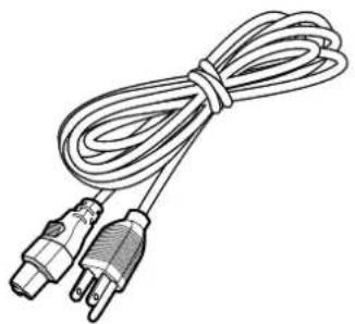
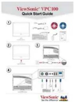
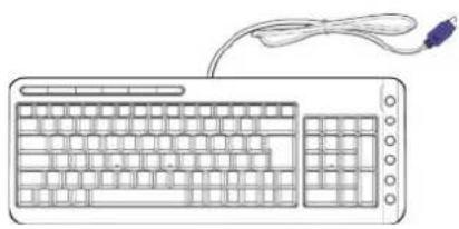
Package Contents
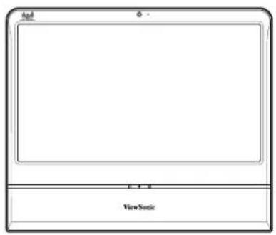
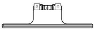
The following items come with your package. If any of them is damaged or missing, please contact your retailer.
natural_image
Pure technical line drawing of a mechanical component with no text or symbols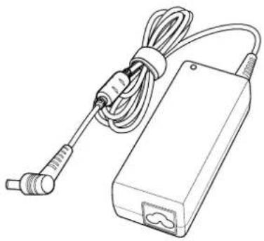
natural_image
Line drawing of a handheld electronic device with coiled cable and connector (no text or symbols)All-in-One PC Stand Power adapter
natural_image
Line drawing of a coiled cable with two connectors (no text or symbols)Power cord ViewSonic Wizard CD


System Recovery and Driver Disk
natural_image
Line drawing of a computer keyboard with a cord and cable, no text or symbols present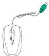
natural_image
Simple line drawing of a computer mouse with a green cable (no text or symbols)Quick Start Guide Keyboard Mouse
NOTE
Keyboard and mouse will be based on actual received units.
Features
All-in-one
The functionality of a standard multiple-parts computer and its monitor are combined together in this all-in-one PC. With a built-in card reader, an optical disc drive, and I/O ports, you can connect various peripherals to maximize computer performance.
Space saver
The slim and sleek design provides more desk space. Because of its compactness, fewer cables are required which creates a tidy and uncluttered work space.
High video quality
The 19" (18.5" viewable) LCD display supports an optimal resolution of 1366x768.
Mountable
For more flexibility options, use VESA mounting to hang this All-in-One PC on the wall.
Low power consumption
This All-in-One PC consumes a maximum of 65 watts of power with active PFC.
System Overview
Front View
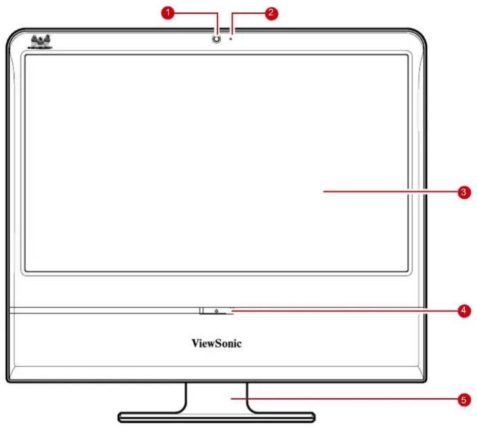
| No. Item Description | ||
| 1 Webcam | Use for taking pictures, recording videos, and video conferencing. | |
| 2 Microphone | Use for chatting and other interactive applications. | |
| 3 LCD display | Provides visual output on a 1366x768 resolution display. | |
| 4 Power button / LED | Press to power on / off the All-in-One PC. The power LED turns blue when the All-in-One PC is turned on. | |
| 5 Stand Holds the All-in-One PC in place. | ||
Rear View
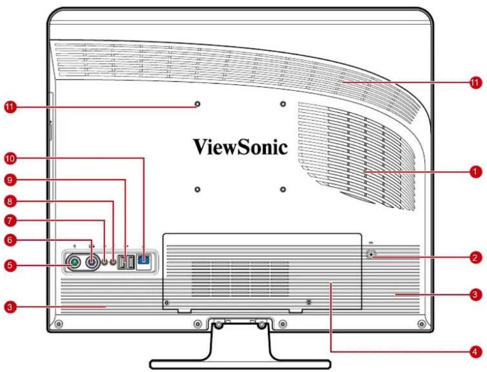
| No. Item Description | ||
| 1 Cooling vent | Used for air convection to prevent the All-in-One from overheating. Do not cover the cooling vent . | |
| 2 Power jack inlet Use to connect the power adapter. | ||
| 3 Stereo speakers Output high quality sound with Hi-Fi function. | ||
| 4 | HDD and memory compartment | Contains the hard disk and memory modules. Do not cover the compartment ventilation holes. |
| 5 Mouse port Connects a PS/2 | ^ mouse to the All-in-One PC. | |
| 6 Keyboard port Connects a PS/2 | ^ keyboard to the All-in-One PC. | |
| 7 Headphone jack Connects a headphone to the All-in-One PC. | ||
| 8 External microphone jack | Connects a external microphone to the All-in-One PC. | |
| 9 USB ports | Connect USB devices such as a mouse, keyboard, printer, scanner, and other peripherals. | |
| 10 RJ-45 LAN jack | Connects to a local area network (LAN) using a network cable. | |
| 11 VESA mount holes | Mount the All-in-One PC on the wall using VESA mounts. | |
NOTE
VESA mounts are not included in the package and are sold separately.
Side Views
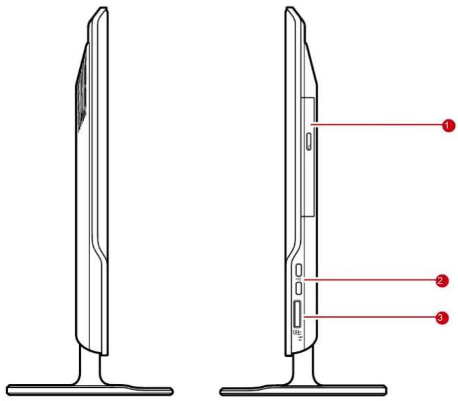
| No. Item Description | ||
| 1 Optical disk drive Plays or records DVD or CD disk | ||
| 2 USB ports | Connect USB devices such as a mouse, keyboard, printer, scanner, and other peripherals. | |
| 3 Card reader port | Supports memory cards including XD (eXtreme Digital), SD (Secure Digital), SDHC (SD High Capacity), MS (Memory Stick), MS Pro (Memory Stick Pro), or MMC (Multi-media Card) cards. | |
Chapter 2 Installation
This chapter will guide you in installing necessary and additional components to maximize the system performance of your All-in-One PC. The following topics are covered:
- Attaching the Stand
- Tilting the Screen
- Removing the Stand
- Connecting PS/2 ^ Devices
- Connecting the Power
- Connecting Audio Components
- Connecting USB Devices
- Connecting to a Network
Attaching the Stand
- Lay the All-in-One PC on a flat and stable surface. Use a soft cloth to protect the display screen.
- Attach the stand. Tighten the stand until it is firmly locked in place.
- Tighten the screw on the bottom of the stand.
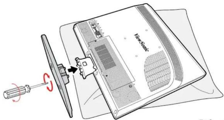
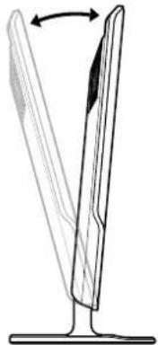
5° front and 15° back
Tilting the Screen
After installing the stand, the screen can be tilted about 20° to suit the user's preference.
natural_image
Diagram of a blade-like structure with an arrow indicating rotation, no text or symbols presentRemoving the Stand
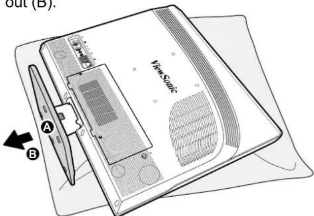
Should there be a need to detach the stand (i.e., for wall mounting), follow the steps below:
- Lay the All-in-One PC on flat and stable surface. Use a soft cloth to protect the display screen.
- Release screw located on bottom of stand (A).
- Pull the stand out (B).
Connecting PS/2 ^® Devices
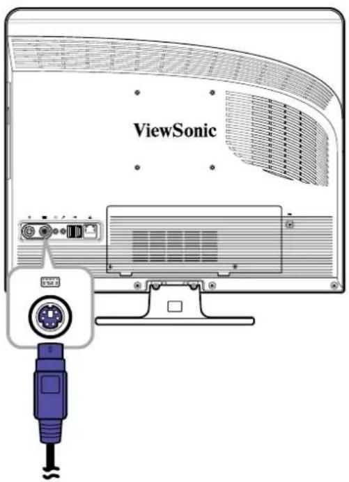
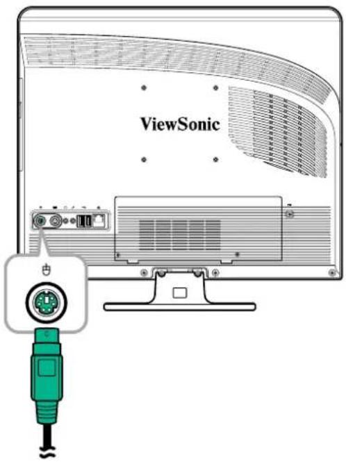
You can connect a keyboard and a mouse using the PS/2 ^® ports on the rear of your All-in-One PC. Before making any connections, ensure that the All-in-One PC is turned off.
Connecting a PS/2 ^® Keyboard
Plug the keyboard's PS/2 ^ cable into the purple PS/2 ^ port of the All-in-One PC.
Connecting a PS/2 ^® Mouse
Plug the mouse's PS/2 ^ cable into the green PS/2 ^ port of the All-in-One PC.
NOTE
- The PS/2 devices should be connected when the unit is powered off. This will allow Windows to detect the devices once the system is turned on.
- You can also connect a USB keyboard or mouse using the USB ports.
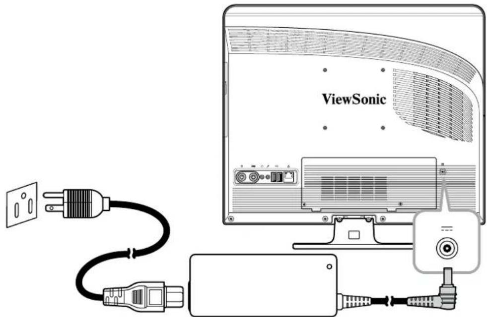
Connecting the Power
- Connect the power adapter to the power jack of the All-in-One PC.
- Connect the power cord to the power adapter.
- Plug the power cord into an electrical outlet.
NOTE
When disconnecting the power, always unplug the power cord from the electrical outlet first. Use the cord's head to unplug, never pull the cable.
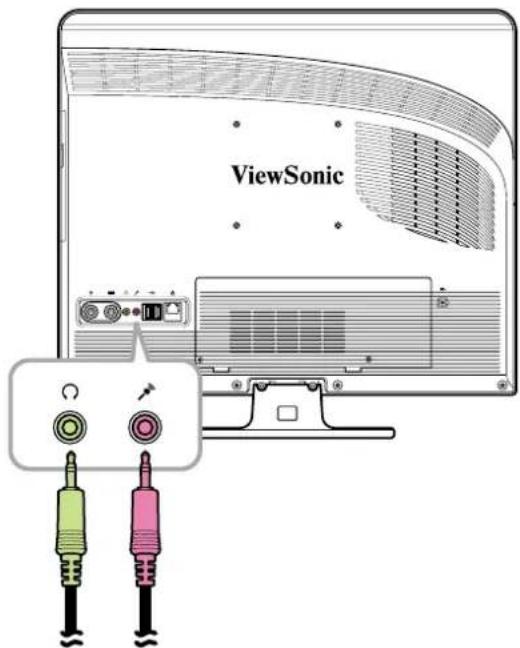
Connecting Audio Components
Connecting the Headset
Plug the stereo headphone cable into the Headphone jack (light green) of your All-in-One PC.
Connecting a Microphone
Plug the microphone cable into the Microphone jack (pink) of your All-in-One PC.
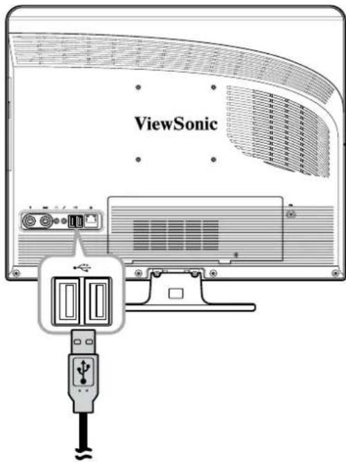
Connecting USB Devices
Your All-in-One PC has four USB ports, two ports are located at the rear (see picture on the right) and two at the right side of the All-in-One PC.
Use these ports to connect USB devices, such as a printer, scanner, keyboard, mouse, USB memory drive and a digital camera among others.
Simply plug the USB cable of the device to the USB port of the All-in-One PC.
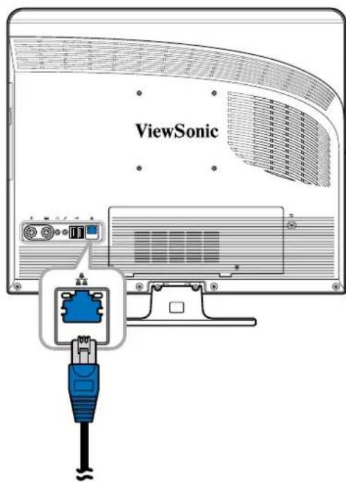
Connecting to a Network
Connect to a local area network (LAN) using the RJ-45 LAN jack of your All-in-One PC.
- Plug one end of the network cable to the RJ-45 LAN jack at the rear of your All-in-One PC.
- Connect the other end to a network hub or a wall socket.
To ensure proper connection, check the LAN jack's LED indicators.

| LED Color LED State Condition | |||
| Activity LED Yellow | Yellow | Off LAN link is not established. | |
| On (Steady) LAN link is established. | |||
| On (Flashing) | The All-in-One PC is communicating with other computers on the network. | ||
| Link LED | Green | Off 10 Mbit/sec | data rate is selected. |
| On 100 Mbit/sec | data rate is selected. | ||
| Orange On 10 | 00 Mbit/sec data | rate is selected. | |
Chapter 3 Operating
This chapter describes some of the basic All-in-One PC operations. The following topics are covered:
• Using the Power Button
• Using the Card Reader
• Using the Optical Disc Drive
- Using the Keyboard
Using the Power Button
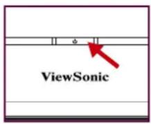
Turning On the All-in-One PC
Press the power button to turn on your All-in-One PC.
WARNING
Turning off your computer before it fully boots, may cause an error the next time you turn on your All-in-One PC.
Turning Off the All-in-One PC
In Windows XP ^® , click Start > Turn Off Computer > Turn Off or push the power button.
NOTE
You can configure Windows to automatically shut down when you press the power button. To do this, click Start > Control Panel > Power Options > Advanced tab. In the Power buttons option, select "Shut down" from the list. Be sure to shut down all running applications before powering off.
Using the Card Reader
The built-in card reader supports various types of memory cards, such as XD, SD, SDHC, MS, MS Pro, and MMC.
Inserting the card
- Insert the card with the metallic connectors facing towards you.
- Push gently until the card clicks into place.
Removing the card
NOTE
Before removing a memory card, use the configuration utility on the taskbar to stop the memory card operation. Failure to do so may result in data loss.
- Push the card gently to eject it.
- Pull the card out from the port.
Using the Optical Disc Drive
Inserting a Disc
- Press the eject button on the disc tray.
- Pull the tray out.
- With the disc label side up, place the disc on the center of the tray and snap into place.
- Gently push the tray back into the drive.
Removing a Disc
- Press the eject button on the disc tray.
- Pull the tray out.
- With your thumb on the center of the tray, pull the disc by its side with your index finger to release.
WARNING
Do not remove the disc while the computer is still reading or playing it.
Using the Keyboard
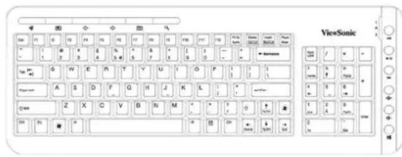
A PS/2 keyboard is supplied with VPC100 computer.
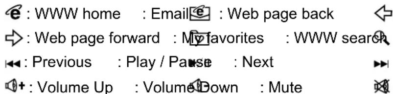
The keyboard uses a standard key arrangement with additional keys that perform specific functions.
Hot keys
NOTE
Keyboard and mouse will be based on actual received units.
Chapter 4 BIOS Setup Utility
BIOS Setup Utility is a program for configuring the BIOS (Basic Input/Output System) settings of the computer.
BIOS is a layer of software called firmware that translates instructions from other layers of software into instructions that the computer hardware can understand. The BIOS settings are needed by your computer to identify the types of installed devices and establish special features.
This chapter tells you how to use the BIOS Setup Utility.
When to Use the BIOS Setup Utility
You need to run the BIOS Setup Utility when:
- You see an error message on the screen requesting you to run Setup.
- You want to restore the factory default settings.
- You want to modify some specific settings of the hardware.
- You want to modify some specific settings to optimize system performance.
Starting BIOS Setup
A keyboard is required to access and make selections in the BIOS Setup Utility. Make sure the keyboard is properly installed before you power up your All-in-One PC.
NOTE
- The Setup screens shown in this chapter are for your reference only. The actual items or settings may slightly differ from that on your computer.
- The Setup utility may have been updated after the publication of this user guide.
- The settings you select in your operating system might override similar settings in the Setup.
To run BIOS Setup, follow the steps below:
- Turn on the All-in-One PC.
- When the ViewSonic® logo appears, quickly press the Delete button on the keyboard.
NOTE
If Windows operating system starts up before you press the Delete button and you still wish to enter the BIOS Setup, restart the All-in-One PC then follow the same procedures above.
Moving Around and Making Selections
The following table lists the control keys you will use to move around and select BIOS settings.
| Key Function | |
| ↑ and Move to the previous / next item | |
| ← and Move to the previous / next menu screen | |
| + and - Increase / decrease fi eld values | |
| Tab and Shift-Tab Go to the next / previous fi eld | |
| Enter Brings | up the sub-menu when availableOpens or closes the options window when an item is selected |
| Esc Exits the | BIOS Setup UtilityReturns to the previous menu if in a sub-menuCloses the option window if one is open |
| Home Go to | the top of the screen |
| F1 General | help |
| F2 / F3 Changes | the BIOS' on-screen display color |
| F7 Discards | changes |
| F8 Loads failsafe defaults | |
| F9 Loads optimal defaults | |
| F10 Saves and exits BIOS | |
Menu
The BIOS Setup Utility is divided into six menu categories: Main, Advanced, Boot, Security, Chipset, and Exit. Use the left and right arrow keys to move through the menu selections.
Sub-menu
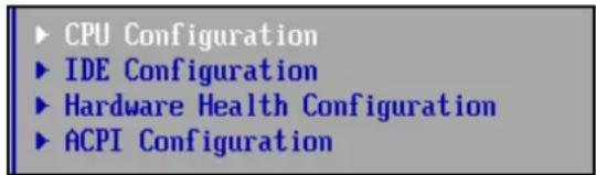
Inside the menu window are the sub-menus. Highlighted items denote that the sub-menu options can be changed. Use the up and down arrow keys to move through the
sub-menu.
A sub-menu with a pointer symbol on the left indicates that more options can be launched from this item. To exit a sub-menu, press [Esc].
General Help
You can access help from any menu. Press [F1] to view the general help window. It lists the appropriate keys to use to browse and configure BIOS settings.
Main Menu
The Main menu lets you adjust the system time and date. It also displays the processor, memory and BIOS version information.
![BIOS SETUP UTILITY Jain Advanced Boot Security Chipset Exit System Overview BIOS Information Version :A7437IUI U1.02 Build Date:01/15/09 Processor Speed :255MHz Count :255 System Memory Size :1024MB System Time [23:20:28] System Date [Wed 01/09/2002] Use [ENTER], [TAB] or [SHIFT-TAB] to select a field. Use [+] or [-] to configure system Time. + Select Screen ↑1 Select Item +- Change Field Tab Select Field F1 General Help F10 Save and Exit ESC Exit v02.61 (C) Copyright 1985-2006, American Megatrends, Inc.](/content/2026/05/859090/images/b2c0c8106a0db257b78b4cbc907f9244acdc61fac2ba6144bcd06dd98a8f215c.jpg)
To adjust the time, go to System Time. To adjust the date, go to System Date.
Press [Tab] or [Shift Tab] to go to the next / previous field, then use + or - keys to adjust the values.
Advanced Menu
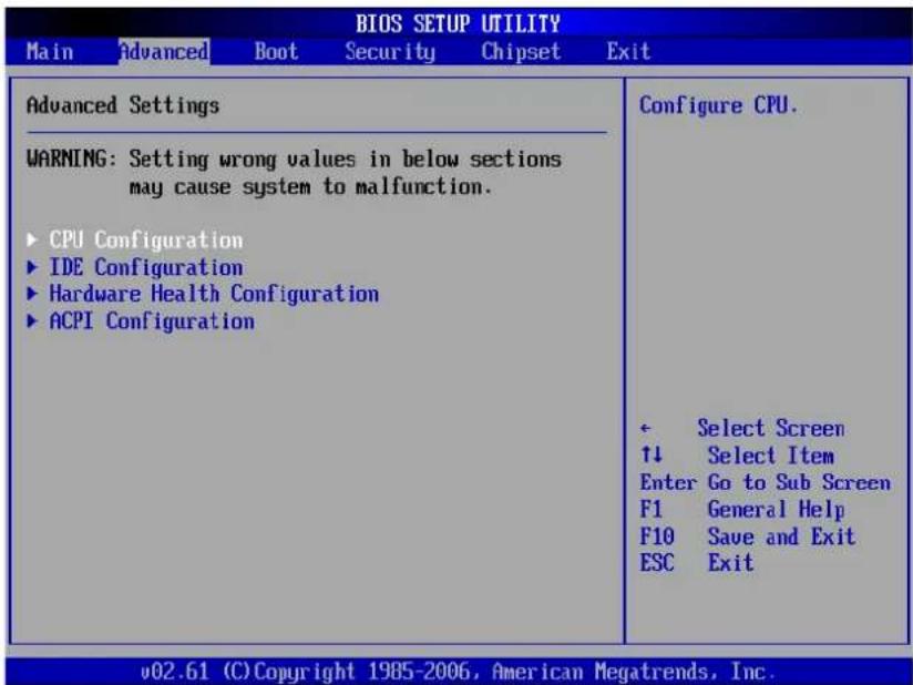
WARNING
If you are not familiar with these settings, it is recommended to use the default configuration for the Advanced Menu options. Setting the wrong values may cause the system to malfunction.
The Advanced Menu lets you view and configure the following:
CPU Configuration
![BIOS SETUP UTILITY Advanced Configure advanced CPU settings Module Version:3F.0E Manufacturer:Intel Frequency :255MHz FSB Speed :532MHz Cache L1 :15362 KB Cache L2 :0 KB Ratio Actual Value:12 Hyper Threading Technology [Enabled] Intel(R) SpeedStep(tm) tech [Enabled] Options Disabled Enabled + Select Screen ↑↓ Select Item +- Change Option F1 General Help F10 Save and Exit ESC Exit v02.61 (C)Copyright 1985-2006, American Megatrends, Inc.](/content/2026/05/859090/images/932c6f45eb20946a1bbf0f39679a9883cb995eaf55ad3a3ea453c5947a53ab65.jpg)
The CPU Configuration displays your All-in-One PC's CPU specification, such as the module version, manufacturer, frequency, speed among others. This submenu allows you to enable or disable the following settings:
- Hyper Threading Technology: Hyper Threading Technology provides faster response time and improves system performance. With Hyper Threading Technology:
- You can run demanding applications simultaneously without slowing down system response time. For example, you can run multimedia applications or play the latest games and still perform a virus scan in the background.
• You can have faster Internet applications. - It is compatible with 32-bit applications and also ready for the future 64-bit technology.
- Intel® SpeedStep™ tech: Intel® SpeedStep™ technology provides average power savings. If enabled, it allows the system to adjust the processor voltage and core frequency and decreases power consumption.
IDE Configuration
The IDE Configuration displays the status of IDE devices installed in your All-in-One PC. When the system starts up, BIOS automatically detects the connected IDE devices.
![BIOS SETUP UTILITY Advanced IDE Configuration ► Onboard SATA#1 : [Hard Disk] ► Onboard SATA#2 : [Not Detected] While entering setup, BIOS auto detects the presence of IDE devices. This displays the status of auto detection of IDE devices. ← Select Screen ↑↓ Select Item Enter Go to Sub Screen F1 General Help F10 Save and Exit ESC Exit v02.61 (C) Copyright 1985-2006, American Megatrends, Inc.](/content/2026/05/859090/images/c024a47c5ea80278092ae348d26e015656479d0ba49cc66c066d5f5d3253d9d6.jpg)
WARNING
If you are not familiar with these configurations, it is recommended to allow BIOS to auto detect the devices. Do not manually change these settings to ensure system performance.
Hardware Health Configuration
This sub-menu displays the hardware condition of your All-in-One PC.
| Hardware Health Configuration | |
| CPU Temperature :76℃/160℉ System Temperature :36℃/96℉ | |
| System Fan Speed :N/A | |
| UCORE :1.136 U 5USB :5.045 U UCCS :4.961 U 12V :12.144 U UBAT :3.280 U | |
| Select Screen ↑↓ Select Item F1 General Help F10 Save and Exit ESC Exit |
ACPI Configuration
The ACPI Configuration sub-menu allows you to configure the Advanced Configuration and Power Interface (ACPI) settings. The General ACPI Configuration is under this sub-menu.
| BIOS SETUP UTILITY Advanced | |
| ACPI Settings ► General ACPI Configuration | General ACPI Configuration settings ← Select Screen ↑↓ Select Item Enter Go to Sub Screen F1 General Help F10 Save and Exit ESC Exit |
| v02.61 (C) Copyright 1985-2006, American Megatrends, Inc. | |
Press [Enter] to launch the General ACPI Configuration screen. Press [Enter] again to view the ACPI state.
| BIOS SETUP UTILITY | |
| Advanced | |
| General ACPI Configuration | Select the ACPI state used for System Suspend. |
| Suspend node [S3 (STR)] | |
| ← Select Screen ↑↓ Select Item +- Change Option F1 General Help F10 Save and Exit ESC Exit | |
| v02.61 (C)Copyright 1985-2006, American Megatrends, Inc. | |
In the above screen, the current setting is displayed. Press [Enter] to change the ACPI state to use when the system goes to suspend mode.
Available options are:
- S1 (POS): Power On Standby. All processor caches are flushed and the CPU stops executing instructions. The CPU and RAM power are maintained, however, other devices may be powered down.
- S3 (STR): Commonly referred to as Standby or Sleep. RAM is still powered.
Boot Menu
The Boot menu lets you configure settings and the boot sequence to follow when the system boots up.
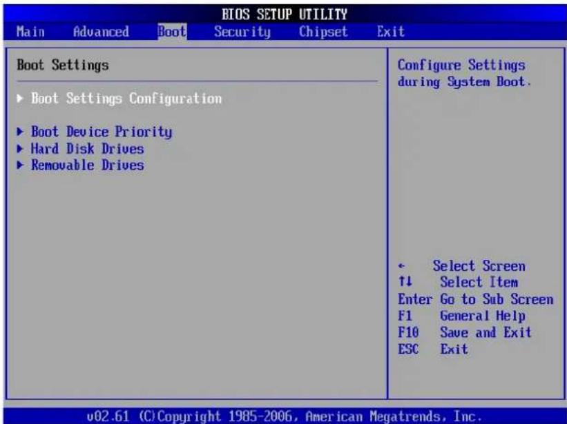
NOTE
The available sub-menu options may vary depending on the installed devices on your All-in-One PC.
Boot Settings Configuration
With this sub-menu, you can configure the type of system boot to execute.
| BIOS SETUP UTILITY | |
| Boot | |
| Boot Settings Configuration | Allows BIOS to skip certain tests while booting. This will decrease the time needed to boot the system. |
| Quick Boot [Enabled] Full logo display [Enabled] Bootup Num-Lock [On] | |
| ← Select Screen ↑↓ Select Item +- Change Option F1 General Help F10 Save and Exit ESC Exit | |
| v02.61 (C) Copyright 1985-2006, American Megatrends, Inc. | |
- Quick Boot: Enable Quick Boot to allow BIOS to skip certain tests while booting. This will decrease the time needed to boot the system.
- Full logo display: When disabled, the normal POST (Power On Self Test) messages are displayed when the system boots up. When enabled, ViewSonic® logo is displayed instead.
- Bootup Num-Lock: Turn the "Power-on state for Numlock" on or off.
Boot Device Priority
This sub-menu lets you specify the boot priority sequence from the available devices.
| BIOS SETUP UTILITY | |
| Boot | |
| Boot Device Priority | |
| 1st Boot Device [USB:Generic- Multi] 2nd Boot Device [SATA:PM-WDC WD1600] | Specifies the boot sequence from the available devices. A device enclosed in parenthesis has been disabled in the corresponding type menu. |
| ← Select Screen ↑↓ Select Item +- Change Option F1 General Help F10 Save and Exit ESC Exit | |
| v02.61 (C) Copyright 1985-2006, American Megatrends, Inc. | |
To change the specified device, press [Enter] to select an available device from the list.
Hard Disk Drives
If your All-in-One PC has more than one hard drive, use this sub-menu to specify the boot sequence for the available hard drives, or disable the hard disk from the boot sequence.
| BIOS SETUP UTILITY | |
| Boot | |
| Hard Disk Drives | Specifies the boot sequence from the available devices. |
| 1st Drive [SATA:PM-WDC WD1600] | |
| Select Screen ↑↓ Select Item Change Option F1 General Help F10 Save and Exit ESC Exit | |
| v02.61 (C) Copyright 1985-2006, American Megatrends, Inc. | |
Removable Drives
Use this sub-menu to specify the boot sequence for the available removable drives, or disable the removable drive from the boot sequence.
| BIOS SETUP UTILITY | ||
| Boot | ||
| Removable Drives | Specifies the boot sequence from the available devices. | |
| 1st Drive 2nd Drive | [USB:Generic-Multi] [USB:Y-E USB-FDD] | |
| ← Select Screen ↑↓ Select Item +- Change Option F1 General Help F10 Save and Exit ESC Exit | ||
| v02.61 (C) Copyright 1985-2006, American Megatrends, Inc. | ||
Security Menu
The Security menu displays the security settings and lets you set up and change the supervisor or user password. Available options on this screen may vary depending on the type of passwords set.
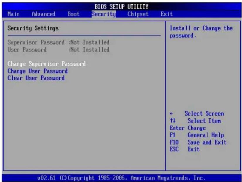
Supervisor Password
The Supervisor can access and change setup utilities. He can also define the limitation of user access.
To set or change the supervisor password:
- Select Change Supervisor Password.
- Type the password, then press [Enter]. The password can be an alphanumeric character of up to 6 characters in length.
- Re-type the password to confirm, then press [Enter].
Once the Supervisor password is set, you can change the User Access Level. The access level options are:
• Full Access: Users can access and change all BIOS settings.
- Limited: Users are only allowed to change basic settings such as date and time.
- No Access: Users cannot access the BIOS Setup Utility.
• View Only: Users can view the BIOS Setup Utility but cannot change the settings.
User Password
To set or change the user password:
- Select Change User Password.
- Type the password, then press [Enter]. The password can be an alphanumeric character of up to 6 characters in length.
- Re-type the password to confirm, then press [Enter].
The Access level defined by the Supervisor determines the users' setup utility access.
Password Check
When a Supervisor or User password has been set, the Password Check option will be available in the Security Menu. With this option, you can configure when the system will prompt you for the password:
- Setup: You are required to enter the password every time you access the BIOS Setup Utility.
• Always: You are required to enter the password on every system boot.
Clear the Password
- Deleting the Supervisor Password
- Select Change Supervisor Password.
- When prompted to enter the new password, just press [Enter].
- A message will appear to confirm password is uninstalled. Press [Enter].
- Deleting the User Password
- Select Clear User Password.
- A message will appear to confirm clearing of password, select Ok then press [Enter].
NOTE
Once you have set the Supervisor Password, you cannot start your computer without entering the password. Be sure not to forget the password. Write down your password and keep it safe and private from other people.
Chipset Menu
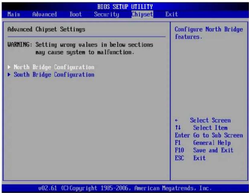
The Chipset menu lets you configure the chipset registers and optimize your system's performance. It consists of the following sub-menu:
WARNING
If you are not familiar with chipset settings, it is recommended to use the default configuration. Setting the wrong values may cause the system to malfunction.
North Bridge Configuration
Your All-in-One PC uses Intel® 945GSE North Bridge Chipset. North Bridge chipset extends to the north of PCI in support of CPU, memory/cache and other performance critical capabilities.
![BIOS SETUP UTILITY Chipset North Bridge Chipset Configuration Internal Graphics Mode Select [Enabled, 8MB] DUMT Mode Select [DUMT Mode] DUMT/FIXED Memory [128MB] High Performance Event Timer [Disabled] Select the amount of system memory used by the Internal graphics device. + Select Screen ↑↓ Select Item +- Change Option F1 General Help F10 Save and Exit ESC Exit v02.61 (C) Copyright 1985-2006, American Megatrends, Inc.](/content/2026/05/859090/images/3fb018a1542dc8e06f78e6dbe29f857212eef951c1a92eb976538e02220ee4cd.jpg)
- Internal Graphics Mode Select: Selects the amount of system memory used by the internal graphics device.
- DVMT Mode Select: Dynamic Video Memory Technology (DVMT) is a concept used in integrated video wherein the optimum amount of memory is dynamically allocated and de-allocated as needed to balance graphics and system performance. Available modes are: Fixed, DVMT, and Combo.
- DVMT/FIXED Memory: Set the amount of memory allocated for DVMT.
- High Performance Event Timer: Select whether to enable or disable this option.
South Bridge Configuration
Your All-in-One PC uses Intel® ICH7M South Bridge Chipset. South Bridge chipset is not directly connected to the CPU, instead the North Bridge chipset ties it to the CPU. The South Bridge Chipset implements the slower performance capabilities, such as the audio controller, PCI bus, and power management among others.
![BIOS SETUP UTILITY Chipset South Bridge Chipset Configuration Audio Controller [Azalia] Wireless Lan Control [On] Camera Control [On] Onboard LAN Boot [Disabled] Restore on AC Power Loss [Power Off] Advanced Resume Event Controls PS2 KB/MS Wake up [Disable] Resume On RTC Alarm [Disabled] Options Azalia AC'97 Modem Only All Disabled ← Select Screen ↑↓ Select Item +- Change Option F1 General Help F10 Save and Exit ESC Exit v02.61 (C) Copyright 1985-2006, American Megatrends, Inc.](/content/2026/05/859090/images/a09bdc758005449b6cf0fd0b0e49b466afbcea481d6c518ec27acb36b8c15484.jpg)
To change the settings, select an item then press [Enter] to view the options.
• Audio Controller: Select the audio controller among the list.
- Wireless Lan Control: Turn wireless LAN control on or off.
- Camera Control: Turn camera control on or off.
- Onboard LAN Boot: Enable or disable Onboard LAN boot.
- Restore on AC Power Loss: Select the mode when system is restored after an AC power loss. Options are: Power Off, Power On, and Last State.
- PS2 KB/MS Wake up: Enable or disable PS/2 keyboard and mouse wake up controls.
- Resume On RTC Alarm: Enable or disable RTC to generate wake events. When enabled, the following items are required:
- RTC Alarm Date (Days): Use [+] and [-] keys to adjust the date.
- RTC Alarm Time: Press [Tab] to select a field. Use [+] and [-] keys to adjust the values.
Exit Menu
The Exit menu lets you save or discard any modifications made to the BIOS or load system default values.
| BIOS SETUP UTILITY | |
| Main Advanced Boot Security Chipset Exit | |
| Exit Options Save Changes and Exit Discard Changes and Exit Discard Changes Load Optimal Defaults Load Failsafe Defaults | Exit system setup after saving the changes. F10 key can be used for this operation. - Select Screen ↑↓ Select Item Enter Go to Sub Screen F1 General Help F10 Save and Exit ESC Exit |
| v02.61 (C) Copyright 1985-2006, American Megatrends, Inc. | |
Save Changes and Exit
Select this option to save modified settings and exit BIOS.
Discard Changes and Exit
Select this option to exit BIOS without saving the modified settings.
Discard Changes
Select this option to discard any changes.
Load Optimal Defaults
Select this option to load optimal default values.
Load Failsafe Defaults
Select this option to load fail safe default values.
To perform an option, do the following:
- Select an item.
- Press [Enter]. A confirmation message appears.
- Select Ok to proceed or Cancel to cancel the operation.
Chapter 5 System Recovery
Your All-in-One PC supports system recovery to enable users to restore the system to its default settings. This function is useful in the event of a system failure or when you forget system passwords.
This chapter covers the following topics:
- When to Use System Recovery
- Running ViewSonic® Recovery Manager
• How to create the System Recovery Disc
When to Use System Recovery
You need to run system recovery:
• In the event of a system or hardware failure.
- You need to restore the system back to its default settings.
• You forgot the system password.
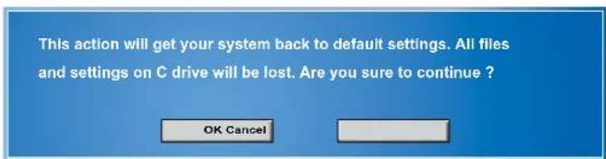
System recovery will format the hard disk and restore the system to its default settings. However all files and other data on drive C: will be deleted.
Running ViewSonic® Recovery Manager
Your All-in-One PC uses ViewSonic® Recovery Manager for system recovery functions.
To run ViewSonic® Recovery Manager, follow the steps below:
- Turn on the All-in-One PC. The system boots up and the ViewSonic® logo appears.
- When the screen displays F3..., quickly press the F3 button on the keyboard.
NOTE
If Windows operating system starts up before you press F3 and you still wish to run System Recovery, restart the All-in-One PC then follow the same procedures above.
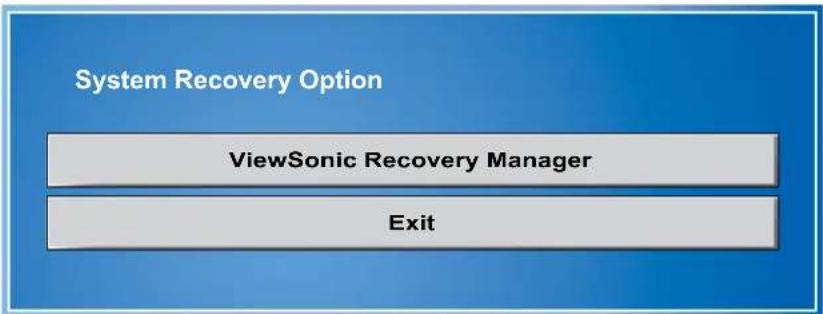
flowchart
graph TD
    A["System Recovery Option"] --> B["ViewSonic Recovery Manager"]
    B --> C["Exit"]
The window below appears.
Click ViewSonic ^® Recovery Manager.3.

Click OK. Another confirmation message appears, as below.4.
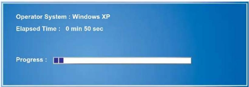
Click OK. System recovery is initiated and the following screen appears.5.
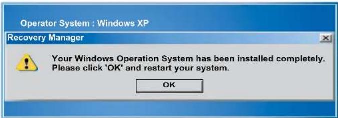
After the system has been restored, the following window appears. 6.
NOTE
Restarting may take several seconds to finish.
- Click OK to restart your All-in-One PC.
- After restarting, Windows Setup Wizard appears to help you configure basic settings. Follow the on screen instructions to complete setup and start using your All-in-One PC.
How to Create the System Recovery Disk
For the first-time use, it is required for you to create a system recovery disk as the backup solution for any accidents. Before moving forward, please make sure your system booting setup is complete and go over the following procedures to get it done.
Step 1. Select the icon of "BurnRecovery" on the desktop screen and click through it.
Step 2. Click [Next] to start the image creation of the recovery disk.
![Thank you for using Recovery Disc Creation Tool The Recovery disc can restore your system back to default settings. If you want to create a recovery disc now, please follow the instructions to proceed. ? Recovering with the recovery disc will format your hard drive. Please click [Next] to continue Next Close](/content/2026/05/859090/images/a2d71c490895322b27a2ad88fb6de47bf2a5bcf830f19dcd77d86991b9496919.jpg)
Step 3. Select "Create and burn a recovery disk" and click [Next] to continue.
![Thank you for using Recovery Disc Creation Tool Options: Create and burn a recovery disc Advanced... Please click [Next] to continue Next Close](/content/2026/05/859090/images/b388b7c0412112886a4173585c0845bbdd5f6e11e69463adff5be93dcba4aaa2.jpg)
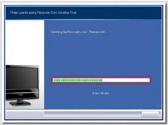
Step 4. The progress bar starts running to create the image of recovery disk. It takes around 2-3 minutes to finish the porcessing.
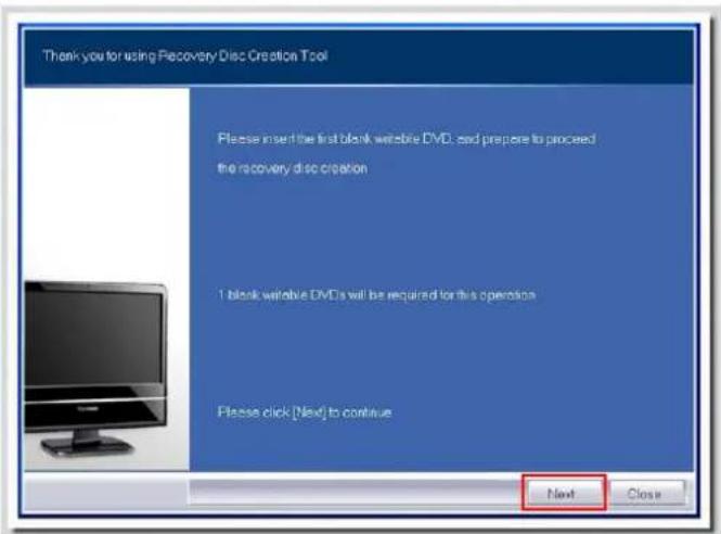
Step 5. Insert a blank DVD-R disk (free bundle with the standard package) and click [Next] to continue.
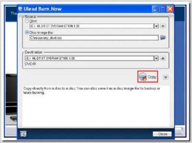
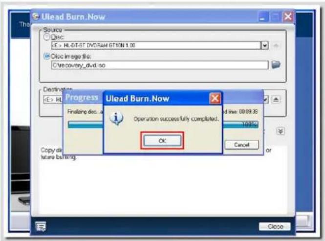
Step 6. The user interface of Ulead Burn. Now pops out. Click [Copy] to start the burning progress. It takes around 9 minutes to finish the processing.
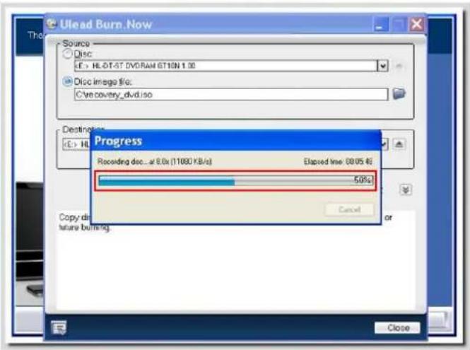
Step 7. The message of "Operation successfully completed" pops out. Click [OK] and take out the disk to finish the recovery disk creation.
Chapter 6 Troubleshooting
This chapter lists some common problems that you may encounter when using your All-in-One PC and describes solutions on how to solve them.
My All-in-One PC does not start.
- Check that the All-in-One PC is connected to an electrical outlet and it is turned on.
- Check that the power cord and all cables are connected firmly.
When I turn on my computer, the message “Operating system not found” appears or Windows does not start
- Check if there is a non-bootable CD inside the optical disk drive. If there is a non-bootable CD in the drive, remove the CD then restart the computer.
- Check boot settings in the BIOS Setup Utility, see Chapter 4.
My LCD does not display anything
- Check that the All-in-One PC is connected to an electrical outlet and it is turned on.
- The All-in-One PC may be in Standby mode. Press any key to activate the display.
My computer "locks up"
- Try restarting the All-in-One PC. On the Windows taskbar, click Start > Turn Off Computer > Restart.
- Press the power switch.
- If your computer locks up while playing a DVD-ROM/CD-ROM, stop the DVD-ROM/CD-ROM, and restart the computer by pressing Ctrl+Alt+Delete.
My DVD-ROM drive tray does not open
• Make sure the computer is turned on.
- Press the Eject button on the DVD-ROM/CD-ROM drive.
- If the Eject button does not work, open the tray by inserting a sharp, pointed object into the hole next to the Eject button.
I cannot play a CD-ROM
• Make sure the label of the CD-ROM is facing up.
- If the CD-ROM requires software, make sure the software is installed according to the program's instructions.
- Moisture condensation may have occurred. Leave the computer for at least 1 hour while the computer is turned on.
- Clean the CD-ROM.
- Check the speaker volume.
I cannot play a DVD-ROM
- If a region code warning appears when you are using the DVD player, it could be that the DVD-ROM you are trying to play is incompatible with the DVD-ROM drive in your All-in-One PC. The region code is listed on the disc's packaging.
- If you hear audio but cannot see video, your computer's video resolution may be set too high. For best results, change the display settings, click Start > Control Panel > Settings.
- If you see video but cannot hear audio, check all of the following: Make sure your DVD player's mute setting is off. Check the master volume setting in the audio Mixer.
- Check that the drivers are installed properly, click Start > Control Panel > System > Device Manager.
- A dirty or damaged disc may cause the computer to “hang” while it tries to read the disc. If necessary, reboot the computer, remove the disc, and then check that it is not dirty or damaged.
My speakers have no sound
- Check the master volume setting in the audio Mixer.
- If you are using an application that has its own volume control, check that the volume is turned up.
- If you have connected an audio cable to the Headphone connector, disconnect the cable.
My internet connection has problems
- Have your phone company check that your phone line is free from any line noise.
- If your problem is fax-related, check that there are no problems with the fax machine and that it is compatible with fax modems.
- If you are having a problem connecting with your Internet Service Provider (ISP), check that the ISP is not experiencing technical problems, or
- If you have a second phone line available, try connecting the modem to that line.
- Check the ADSL settings and connection and make sure All-in-One PC is properly configured for Internet access.
- The wireless LAN data transfer speed is affected by distance and obstructions between devices and access points. To maximize the data transfer speed, please choose any access point you may be using closer to All-in-One PC.
My microphone does not work
- For webcam built-in microphone, please go to Start > Control Panel > Sounds and Audio Devices > Audio to check if it is muted.
- If you are using an external microphone, check that the microphone is plugged into the Microphone connector.
My mouse does not work
- Check that the mouse is plugged into the mouse connector.
- If you connected the mouse while your computer is on, you must restart your computer.
My computer does not shut down
It is best to shut down your computer using the Shut Down command. Using other methods, including those listed here, may result in loss of unsaved data. If the Shut Down command does not work properly, follow these steps:
- Restart the computer by pressing Ctrl+Alt+Delete.
- Press the power switch to turn off the power.
- Unplug the All-in-One PC from the power adapter.
Chapter 7
Other Information
Customer Support
For technical support or product service, see the table below or contact your reseller.
NOTE: You will need the product serial number.
| Country/Region Website | T = TelephoneF = FAX | ||
| Australia/New Zealand www.viewsonic.com.au | AUS= 1800 880 818NZ= 0800 008 822 | service@au.viewsonic.com | |
| Canada www.viewsonic.com | T (Toll-Free)= 1-866-463-4775T (Toll)= 1-424-233-2533F= 1-909-468-1202 | service.ca@viewsonic.com | |
| Europe www.viewsoniceurope.com Contact your reseller | |||
| Hong Kong www.hk.viewsonic.com T= 852 3102 2900 service@hk.viewsonic.com | |||
| India www.in.viewsonic.com T= 1800 11 9999 service@in.viewsonic.com | |||
| Korea www.kr.viewsonic.com T= 080 333 2131 service@kr.viewsonic.com | |||
| Latin America(Argentina) | www.viewsonic.com/la/ T= 0800 | 666 0194 soporte@viewsonic.com | |
| Latin America (Brazil) www.viewsonic.com/la/ T= 0800 891 6984 soporte@viewsonic.com | |||
| Latin America (Chile) www.viewsonic.com/la/ T= 800 440 303 | soporte@viewsonic.com | ||
| Latin America(Columbia) | www.viewsonic.com/la/ T= 01 800 | 915 6588 soporte@viewsonic.com | |
| Latin America (Mexico) | www.viewsonic.com/la/ | T= 001 800 514 6518 | soporte@viewsonic.com |
| Renta y Datos, 29 SUR 721, COL. LA PAZ, 72160 PUEBLA, PUE. Tel: 01.222.891.55.77 CON 10 LINEASElectroser, Av Reforma No. 403Gx39 y 41, 97000 Mérida, Yucatán. Tel: 01.999.925.19.16Other places please refer to http://www.viewsonic.com/la/soporte/index.htm#Mexico | |||
| Latin America (Peru) | www.viewsonic.com/la/ | T= 0800 53458 | soporte@viewsonic.com |
| Macau | www.hk.viewsonic.com T= 853 700 303 service@hk.viewsonic.com | ||
| Puerto Rico & Virgin Islands | www.viewsonic.com | T= 1-800-688-6688 (English)T= 1-866-379-1304 (Spanish)F= 1-909-468-1202 | service.us@viewsonic.comsoporte@viewsonic.com |
| Singapore/Malaysia/Thailand | www.ap.viewsonic.com | T= 65 6461 6044 service@sg.viewsonic.com | |
| South Africa www.viewsoniceurope.com www.viewsoniceurope.com/uk/Support/Calldesk.htm | |||
| United States www.viewsonic.com | T (Toll-Free)= 888-572-9237T (Toll)= 909-444-8801 | service.us@viewsonic.com | |
Limited Warranty
VIEWSONIC® ALL-IN-ONE PC
What the warranty covers:
ViewSonic warrants its products to be free from defects in material and workmanship during the warranty period. If a product proves to be defective in material or workmanship during the warranty period, ViewSonic will, at its sole option, repair or replace the product with a similar product. Replacement Product or parts may include remanufactured or refurbished parts or components. The replacement unit will be covered by the balance of the time remaining on the customer's original limited warranty. ViewSonic provides no warranty for the third-party software included with the product or installed by the customer.
How long the warranty is effective:
ViewSonic VPC products are warranted for (1) year from the first consumer purchase for parts and labor.
User is responsible for the back up of any data before returning the unit for service.
ViewSonic is not responsible for any data lost.
Who the warranty protects:
This warranty is valid only for the first consumer purchaser.
What the warranty does not cover:
- Any product on which the serial number has been defaced, modified or removed.
- Damage, deterioration or malfunction resulting from:
a. Accident, misuse, neglect, fire, water, lightning, or other acts of nature, unauthorized product modification, or failure to follow instructions supplied with the product.
b. Any damage of the product due to shipment.
c. Removal or installation of the product.
d. Causes external to the product, such as electrical power fluctuations or failure.
e. Use of supplies or parts not meeting ViewSonic's specifications.
f. Normal wear and tear.
g. Any other cause which does not relate to a product defect.
-
Any product exhibiting a condition commonly known as "image burn-in" which results when a static image is displayed on the product for an extended period of time.
-
Removal, installation, one way transportation, insurance, and set-up service charges.
How to get service:
- For information about receiving service under warranty, contact ViewSonic Customer Support (Please refer to Customer Support page). You will need to provide your product's serial number.
- To obtain warranty service, you will be required to provide (a) the original dated sales slip, (b) your name, (c) your address, (d) a description of the problem, and (e) the serial number of the product.
- Take or ship the product freight prepaid in the original container to an authorized ViewSonic service center or ViewSonic.
- For additional information or the name of the nearest ViewSonic service center, contact ViewSonic.
4.3: ViewSonic All-in-One PC Warranty
Limitation of implied warranties:
There are no warranties, express or implied, which extend beyond the description contained herein including the implied warranty of merchantability and fitness for a particular purpose.
Exclusion of damages:
ViewSonic's liability is limited to the cost of repair or replacement of the product. ViewSonic shall not be liable for:
- Damage to other property caused by any defects in the product, damages based upon inconvenience, loss of use of the product, loss of time, loss of profits, loss of business opportunity, loss of goodwill, interference with business relationships, or other commercial loss, even if advised of the possibility of such damages.
- Any other damages, whether incidental, consequential or otherwise.
- Any claim against the customer by any other party.
- Repair or attempted repair by anyone not authorized by ViewSonic.
Effect of state law:
This warranty gives you specific legal rights, and you may also have other rights which vary from state to state. Some states do not allow limitations on implied warranties and/or do not allow the exclusion of incidental or consequential damages, so the above limitations and exclusions may not apply to you.
Sales outside the U.S.A. and Canada:
For warranty information and service on ViewSonic products sold outside of the U.S.A. and Canada, contact ViewSonic or your local ViewSonic dealer.
The warranty period for this product in mainland China (Hong Kong, Macao and Taiwan Excluded) is subject to the terms and conditions of the Maintenance Guarantee Card.
For users in Europe and Russia, full details of warranty provided can be found in www.viewsoniceurope.com under Support/Warranty Information.
4.3: ViewSonic All-in-One PC Warranty
Page 2 of 2
AIO PC_LW01 Rev. 1a 02-11-09
Appendix VPC100 Bundle Software
NTI (New Tech Infosystems, Inc.) Media Maker OEM version
For contacts about third-party software products, see the following.
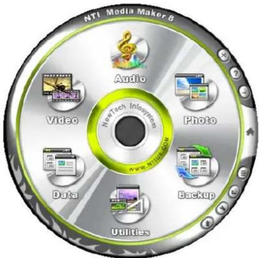
Website: http://www.ntius.com/default.asp
Operation manual: click for more details
WinRAR (40 days trial)
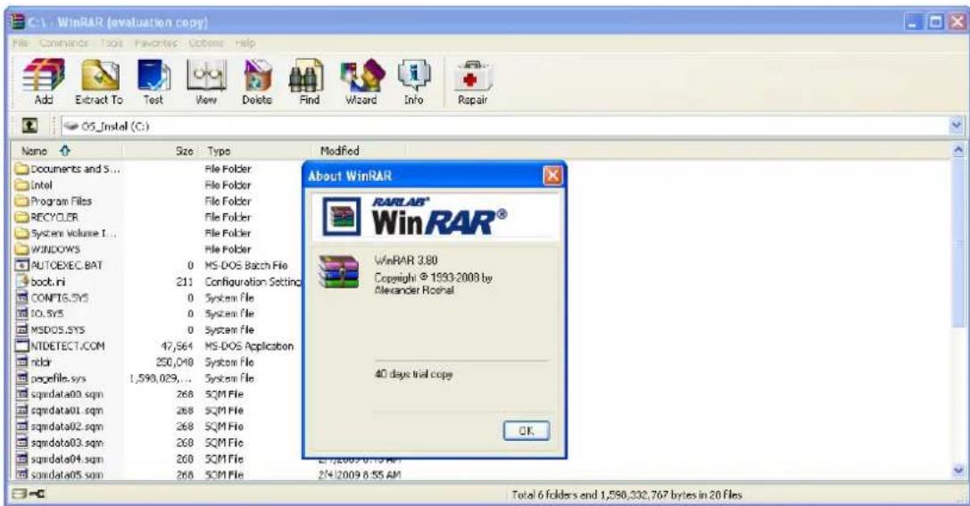
Website: http://www.win-rar.com
For the simplified Chinese version, please check on our Chinese Distributor's website at: http://www.winrar.com.cn/
For the traditional Chinese version, please check on our Taiwanese Distributor's website at: http://www.rar.com.tw/
Trend Micro Internet Security (2009), 60-day trial version
Website: http://us.trendmicro.com/us/about/contact_us/index.html
- VPC100 All-in-One PC
- Table of Contents
- Preface.... iv
- Chapter 1: Getting Started .... 1
- Chapter 2: Installation....7
- Chapter 3: Operating ...... 12
- Chapter 4: BIOS Setup Utility ...... 15
- Chapter 5: System Recovery .... 30
- Chapter 6: Troubleshooting ...... 36
- Chapter 7: Other Information .... 40
- Appendix: VPC100 Bundle Software 43
- Preface
- Compliance Information
- For U.S.A.
- For Canada
- CE Conformity for European Countries
- Following information is only for EU-member states:
- FCC Radiation Exposure Statement
- Industry Canada Notice
- R&TTE Compliance Statement C€!
- Important Safety Instructions
- Declaration of RoHS Compliance
- Copyright Information
- U.S. Patent Numbers
- Product Registration
- For Your Records
- Product disposal at end of product life
- Chapter 1 Getting Started
- Package Contents
- NOTE
- Features
- All-in-one
- Space saver
- High video quality
- Mountable
- Low power consumption
- System Overview
- Rear View
- Chapter 2 Installation
- Attaching the Stand
- Tilting the Screen
- Removing the Stand
- Connecting PS/2 ® Devices
- Connecting a PS/2 ® Keyboard
- Connecting a PS/2 ® Mouse
- Connecting the Power
- Connecting Audio Components
- Connecting the Headset
- Connecting a Microphone
- Connecting USB Devices
- Connecting to a Network
- Chapter 3 Operating
- Using the Power Button
- Turning On the All-in-One PC
- WARNING
- Turning Off the All-in-One PC
- Using the Card Reader
- Inserting the card
- Removing the card
- Using the Optical Disc Drive
- Inserting a Disc
- Removing a Disc
- Using the Keyboard
- Hot keys
- Chapter 4 BIOS Setup Utility
- When to Use the BIOS Setup Utility
- Starting BIOS Setup
- Moving Around and Making Selections
- Menu
- Sub-menu
- General Help
- Main Menu
- Advanced Menu
- CPU Configuration
- IDE Configuration
- Hardware Health Configuration
- ACPI Configuration
- Boot Menu
- Boot Settings Configuration
- Boot Device Priority
- Hard Disk Drives
- Removable Drives
- Security Menu
- Supervisor Password
- User Password
- Password Check
- Clear the Password
- Chipset Menu
- North Bridge Configuration
- South Bridge Configuration
- Exit Menu
- Save Changes and Exit
- Discard Changes and Exit
- Discard Changes
- Load Optimal Defaults
- Load Failsafe Defaults
- Chapter 5 System Recovery
- When to Use System Recovery
- Running ViewSonic® Recovery Manager
- How to Create the System Recovery Disk
- Chapter 6 Troubleshooting
- My All-in-One PC does not start.
- When I turn on my computer, the message “Operating system not found” appears or Windows does not start
- My LCD does not display anything
- My computer "locks up"
- My DVD-ROM drive tray does not open
- I cannot play a CD-ROM
- I cannot play a DVD-ROM
- My speakers have no sound
- My internet connection has problems
- My microphone does not work
- My mouse does not work
- My computer does not shut down
- Chapter 7
- Other Information
- Customer Support
- Limited Warranty
- VIEWSONIC® ALL-IN-ONE PC
- What the warranty covers:
- How long the warranty is effective:
- Who the warranty protects:
- What the warranty does not cover:
- How to get service:
- Limitation of implied warranties:
- Exclusion of damages:
- Effect of state law:
- Sales outside the U.S.A. and Canada:
- Appendix VPC100 Bundle Software
- WinRAR (40 days trial)
- Trend Micro Internet Security (2009), 60-day trial version
Brand : VIEWSONIC
Model : VPC100
Category : Office