
KVM-440 - Computer Accessories D-LINK - Free user manual and instructions
Find the device manual for free KVM-440 D-LINK in PDF.


| Product Type | KVM Switch |
| Number of Ports | 4 |
| Max Video Resolution | 1920 x 1440 |
| Video Connector Type | VGA (DB-15) |
| Console Connectors | 1x VGA, 2x USB (keyboard/mouse), 2x 3.5mm audio |
| Computer Connectors | 4x VGA, 8x USB (keyboard/mouse), 8x 3.5mm audio |
| Switching Method | Push button, Hotkey, AutoScan |
| Power Supply | External AC adapter (9V DC, 1A) |
| Dimensions (W x D x H) | 200 x 80 x 40 mm |
| Weight | 0.5 kg |
| Supported Operating Systems | Windows, macOS, Linux |
| USB Hub | Built-in USB 2.0 hub |
| Audio Support | Pass-through for microphone and speaker |
| Operating Temperature | 0°C to 40°C |
| Compliance | FCC, CE |
| Included Accessories | Power adapter, 4x KVM cables, user manual |
| Safety | Use only provided power adapter. Avoid liquids. |
| Cleaning | Wipe with dry cloth. Do not use solvents. |
| Spare Parts | Contact D-Link support for replacement cables. |
| Warranty | 2 years limited |
Frequently Asked Questions - KVM-440 D-LINK
User questions about KVM-440 D-LINK
0 question about this device. Answer the ones you know or ask your own.
Ask a new question about this device
Download the instructions for your Computer Accessories in PDF format for free! Find your manual KVM-440 - D-LINK and take your electronic device back in hand. On this page are published all the documents necessary for the use of your device. KVM-440 by D-LINK.
USER MANUAL KVM-440 D-LINK
Building Networks for People
KVM-440/450
Version 1.0
PS2/USB Combo KVM Switch
User Manual
Business Class Networking
Table of Contents
Introduction 4
Package Contents ....4
Specifications 5
System Requirements 6
Features 7
Installation 9
Front View 9
Rear View ....10
Single Stage Installation 11
Precautions 11
Console Connection ....12
System Connections ....13
Cascade Chaining 16
Rack Mounting 18
Operation 19
Hot Key Operation 20
Call OSD Menu 20
Leading Hotkey Select 20
Channel Select - Single KVM 21
Specific Channel Selection ....21
Arrow Key Channel Shift Function 22
Channel Select - Cascade Chain Layer 23
Enable / Disable Buzzer Sound ....24
Auto-Scan Function 24
Enter the Auto-scan mode 25
Exit the Auto-scan mode ....25
Auto-scan Mode Options 26
Auto-scan Time Interval 26
Console Lock Function 27
OSD Operation 28
OSD Main Menu 28
Channel Selection in OSD 31
Setup in OSD:
Auto-Scan in OSD:
Console Lock in OSD:
Channel Rename:
Security Setup:
Lock Port:
Table of Contents
Sun Keyboard Emulation 42
Firmware Upgrade Procedures 43
Troubleshooting 48
Contacting Technical Support 49
Warranty 50
Registration 55
Introduction
Thank you for purchasing the D-Link Combo KVM Switch. The D-Link 8/16 Port PS2/USB combo KVM switch is a high-end remote management solution which allows you to control up to 4096 PCs from a single console.
Package.Contents
• 8-Port or 16-Port PS2/USB Combo KVM Switch
- Power Adapter
• CD-ROM with Manual and Software
- Quick Installation Guide
- Rack Mount Bracket Kit Set
• 4-in-1 PS2/USB Combo KVM cable
Specifications
| Number.of.Computers.Controlled | 8 or 16 | |
| Selection.Method | Switch Button, Hot-Key (PS/2 Keyboard) and On-Screen-Display (OSD) | |
| LEDs | Red for PC Selected Green for PC On-Line/ Ready | |
| PC.Connectors.. | 8 / 16 x HDB-15 female, Supports both PS/2 and USB interfaces | |
| Console.Ports.. | Keyboard1 x 6 pin mini-DIN female | |
| Mouse1 x 6 pin mini-DIN female | ||
| Video1 x HDB-15 female | ||
| Firmware.Upgrade.PortMini USB | ||
| Auto-Scan.Interval5 to 90 seconds | ||
| Video.ResolutionMax. Resolution | up to 2048 x1536@65Hz | |
| Hot.SwappableYes | ||
| System.Requirements | Windows 98SE/ME/2000/XP/2003/2007/ Vista, Mac OS9/ OSX, Linux, and Sun Microsystems | |
| Power5V, 2A | ||
| Dimensions.(L.X.W.X.H) 17.3 x 6.1 x 1.5 inch (44 x 15.7 x 4.5 cm) | ||
| Weight1750g / 1900 g | ||
| Housing.materialMetal | ||
| Operating.Temperature32~122°F (0~50°C) | ||
| Humidity | 0%~80% Relative Humidity | |
System.Requirements
For best results, the following System Requirements are recommended:
•.Console
- High-Resolution monitor (VGA, SVGA, etc.)
- PS/2 Keyboard
- PS/2 Mouse
•.Computer.or.Server
The following equipment must be equipped with each computer or server:
- VGA, SVGA, Multisync Graphics Card
- Type A USB port or PS/2 6 pin mini- DIN for Keyboard and Mouse
•.Cables
The KVM Switch uses 4-in-1 PS2/USB combo cables. To purchase the custom cable sets, please contact your reseller.
Features
The KVM-440/450 is designed for easy installation and features on-screen display providing clear and easy navigation:
- Connect your console keyboard/mouse via PS/2.
- Connect computers via PS/2 and/or USB.
• Supports Windows, Linux, Mac OS9/OSX, and Sun Microsystems Operating Systems. - On-Screen-Display (OSD) & Cascade Chain functions.
- Intuitive on-screen menus for quick and efficient navigation.
- Three level password access: Administrator, User and Viewer.
• Supports daisy chaining with up to 3 cascade levels. Cascaded units do not require a special configuration. - Emulates a PS/2 or USB keyboard on each PC allowing them to boot normally without a keyboard error.
- Supports hot-plugging: All computers connected to the KVM switch can be added or removed at any time without shutting down the KVM switch.
• Supports 3 switching methods: - Front Panel Button
- Hot-Keys on a PS/2 keyboard
-
OSD Menu (On Screen Display)
-
Supports Auto-Scan function to switch video inputs automatically among the multiple computers sequentially at preset intervals via OSD menu.
• Supports front panel LED display for PC and/or server status indication
• Supports monitor resolutions up to 2048 x 1536
• Audible feedback when switching - Fully compliant with USB 1.1/2.0 specifications
- Rack mountable in 19" system rack (1U)
Installation Front.View
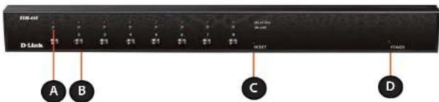
Figure.1-.KVM-440.Front.Panel
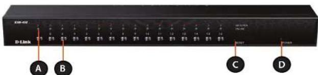
Figure.2.--KVM-450.Front.Panel
| ItemFeatureDescription | ||
| A Status LEDs Selected (Red):A Red LED indicates that the corresponding PC is selected.Online (Green):A Green LED indicates that the corresponding PC is online. | ||
| B | Switch Button | Press the button corresponding to the computer you would like to control via console. |
| C | Reset Switch | Press the Reset switch when you would like to reset the device. The reset switch must be depressed using a thin object like the end of a paper clip, or a ball point pen. |
| D Power LED Indicates that the device is powered on. | ||
Rear.View
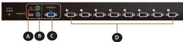
Figure.3.-KVM-440.Rear.Panel
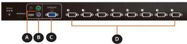
Figure.4.-KVM-450.Rear.Panel
| ItemFeature | Description | |
| A PS/2 Mouse Console Port Connects to the PS/2 mouse | ||
| B PS/2 Keyboard Console Port | Connects to the PS/2 keyboard | |
| C VGA Monitor Console Port | Connects to the VGA monitor | |
| D Computer Connectors Connects to the computers with the 4-in-1 KVM combo cables | ||
Single.Stage.Installation.
Precautions
- Please turn off computers and attached devices before installing the KVM Switch.
- For computers with Keyboard Power On function, please unplug the power cords in advance. Otherwise, the switch may not work properly.
- Some older computers may require you to enable USB in BIOS to make the USB interface work.
Console.Connection
Plug the keyboard, mouse, and monitor into the console ports on the rear panel of the KVM Switch. (Figure 5)
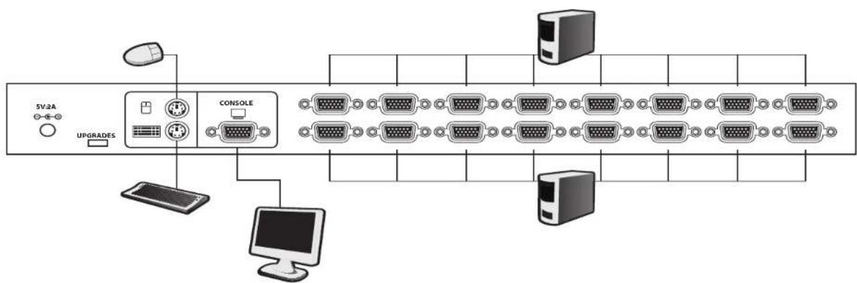
Figure.5.-Console.Connection
System.Connections
Use the 4-in1 KVM combo cable to connect your computers. Refer to the figures and instructions shown below for information about connecting the KVM to PCs.
Note: Please contact your reseller to purchase additional 4-in-1 KVM combo cables.
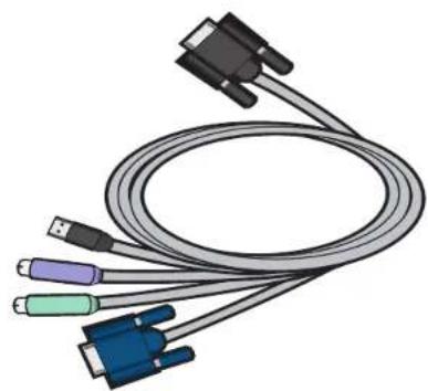
natural_image
Illustration of a multi-pin cable with USB connectors and a black connector (no text or symbols)Figure.6.-4-in-1.KVM.combo.cable
You can connect the KVM switch to computers using one of the three methods shown below:
A. Connect USB, PS/2 Keyboard, PS/2 Mouse and VGA connectors to your computer. We recommend that users connect computers in the manner shown below. (Figure 7)
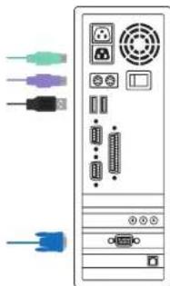
natural_image
Front view of a desktop computer tower with ports and connectors (no text or symbols visible)Figure.7.-USB,PS/2.and.VGA.Setup
B. Connect only PS/2 Keyboard, PS/2 Mouse and VGA connectors to your computer. (Figure 8)
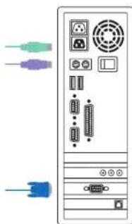
natural_image
Front view of a desktop computer tower with indicator lights and ports (no text or symbols visible)Figure.8.-PS/2.and.VGA.Setup
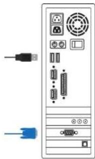
C. Connect only USB and VGA connectors to your computer (Figure 9).
natural_image
Front view of a desktop computer tower with ports and connectors (no visible text or labels)Figure.9.-USB.and.VGA.Setup
Cascade.Chaining
The KVM switch supports cascades of up to 3 levels. Control up to 64/256/4096 PCs from a single console. Cascaded units do not require any special configuration Once connected, the KVM Switches will automatically configure themselves appropriately as the Master or Slave.
To install a cascade chain, please follow the instruction below.
A. Power off any attached computers/devices before installing the KVM Switch.
B. Use the 4-in-1 KVM combo cable (See Figure 6) to connect one or more Slave KVM Switches to any PC port on the Master KVM Switch. The KVM to KVM must be connected through a PS/2 connection. (Please refer to Figure 7 & Figure 8).
C. Plug in the power adapter for the first level Master KVM Switch and connect the Master KVM switch to computers.
D. Plug in the power adapter for each level Slave KVM Switch and connect the Slave KVM switch to computers.
E. The power on sequence should be:
- Master KVM Switch.
- Second level Slave KVM Switch (connected to Master KVM Switch) if needed.
- Third level Slave KVM Switch (connected to second level Slave KVM Switch) if needed.
- All computers connected to Master/Slave KVM Switch.
Initial.Plug-in.Process:
Please plug in the Master KVM Switch first before turning on any other devices like monitor or computers.
Hot.plugging.and.hot swapping:
The KVM switch supports hot plugging and hot swapping.
Section 2 - Installation
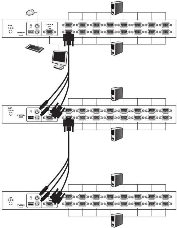
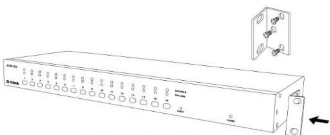
Figure 11 shows you how to attach the mounting brackets to the KVM Switch unit for a standard 19-inch rack cabinet.
-
Attach the mounting brackets onto the sides of the KVM Switch unit using screws. (Figure 11)
-
Install the KVM Switch unit into the rack cabinet.
natural_image
Line drawing of a D4link network switch with labeled ports and an inset showing a socket mounting bracket (no text or symbols on the main body)Figure.11.-Rack.Mounting
Operation
You can select a computer to control with the KVM switch front panel buttons, hotkeys, or OSD.
1. Button Operation
Press the front panel button to select the PC and operate it.
2. Hotkey Operation
Please refer to the Hot Key Operation section.
3. OSD Operation
Please refer to the OSD Operation.
Hot Key Operation Call OSD Menu
Press
Leading Hotkey Select
The two-step hotkey sequence is used for quick function execution. The leading key is
By pressing
The available leading hotkeys are
Set leading hotkey to <Scroll Lock>
<CTRL><CTRL><Scroll Lock><Enter>
Set leading hotkey to <Num Lock>
<CTRL><CTRL><Num Lock><Enter>
Set leading hotkey to <Caps Lock>
<CTRL><CTRL><Caps Lock><Enter>
Note: You can also change the leading hotkey by pressing
Channel.Select.-.Single.KVM
Specific.Channel.Selection
You can select the connected computers using the two-step Hotkey sequence. Press the
Note: You can also select the computers using the OSD menu. Move the indicator bar to the channel using the
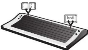
Figure.12.-Specific.Channel.Selection.Hotkey
<Scroll.Lock>.....<Scroll.Lock>.....<1>.....<Enter>.or
<Scroll.Lock>.....<Scroll.Lock>.....<2>.....<Enter>.or
...
...
<Scroll.Lock>.....<Scroll.Lock>.....<16>.....<Enter>
Arrow.Key.Channel.Shift.Function
Press
Switch one channel to the left
<Scroll.Lock>...<Scroll.Lock> <Left.Arrow>
Switch one channel to the right
<Scroll.Lock>....<Scroll.Lock>....<Right.Arrow>
.Channel.Shift.Function
- Start
Channel shift Function
- Switch channels using the
key
Press the left or right
Enable/Disable.<ALT>.channel.shift.function
<Scroll.Lock>.....<Scroll.Lock>.....<ALT>.....<Enter>
Switch.one.channel.to.the.left
<Left.ALT>.....*Left.ALT>
Switch.one.channel.to.the.right
<Right.ALT>.....*Right.ALT>
Channel.Select.-.Cascade.Chain.Layer
You can select the active channel directly under a cascade chain connection. The following hotkey sequence is used for quick channel selection. Press
Select.the.first.layer.channel
<Scroll.Lock>.....<Scroll.Lock>.....<D>.....<1-16>.....<Enter>
Select.the.second.layer.channel
<Scroll.Lock.>....<Scroll.Lock>.....<D>.....<1-16>
......<D>......<1-16.>....<Enter>→ → →
Select.the.third.layer.channel
<Scroll.Lock<Scroll.Lock>.....<D>.....<1>16>
<D> <1-16> → →
Note: With cascading 3 layers, you can select the last layer directly.
Example: Press
D2: layer 1 - channel 2 links to
D5: layer 2 - channel 5 links to
D7: layer 3 - channel 7 selected
Note: You can also select the active channel under cascade chaining in OSD menu. Move the indicator bar to the channel using the
Enable./.Disable.Buzzer.Sound
Press
Note: You can also enable/disable buzzer sound by pressing
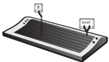
Figure.13.-.Buzzer.Setup.Hotkey
Auto-Scan.Function
Enable the Auto-Scan function by pressing and
The mouse and keyboard will be disabled under this mode. This is necessary to prevent errors such as erratic movement and incorrectly displayed characters from accidentally touching the mouse or keyboard.
Enter.the.Auto-scan.mode
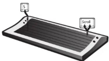
Figure.14.-Auto-Scan.Hotkey
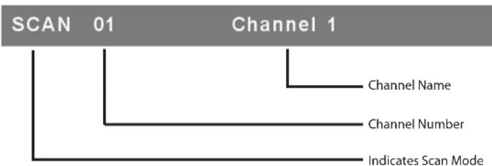
flowchart
graph TD
    A["SCAN 01"] --> B["Channel 1"]
    B --> C["Channel Name"]
    B --> D["Channel Number"]
    B --> E["Indicates Scan Mode"]
Figure.15.-.Auto-Scan.Banner
Exit.the.Auto-scan.mode
Press any key on keyboard to STOP the auto-scan function. Alternatively you may stop the auto-scan function by pressing the button on the front panel of the KVM Switch.
Auto-scan.Mode.Options
There are two auto-scan modes, please refer to the Setup.in.OSD.-.Scan.Mode section to set up the auto-scan mode.
- Scan all computers.
- Scan any computers which are marked for auto-scan.
Auto-scan.Time.Interval
The auto-scan time interval can be adjusted by pressing
Note: You can also enter or exit the auto-scan mode by pressing
Console Lock Function
If the security mode is enabled in OSD mode (by pressing
The KVM switch will be locked until an authorized user logs in.
<Scroll Lock> <Scroll Look> <H> <Enter> →
To unlock the console, please press any key according to the screen message, then key in the User Name and Password. The KVM switch and console devices will be unlocked and returned to the normal status.
Note: You can also execute the console lock function by pressing
OSD Operation OSD Main Menu
Press
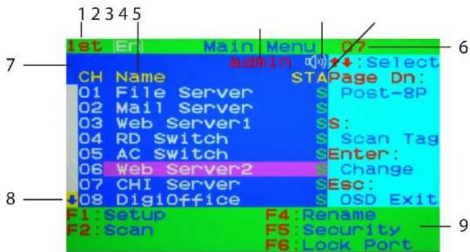
Figure 16: OSD Main Menu
1. KVM Switch layer Number
1st, 2nd or 3rd. indicates the current cascade level.
2. Channel Name
The channel name can be defined using the
The selected channel is highlighted in pink.
A plus mark (+) showing on the left side of the channel name indicates that the port is cascaded.
3. Logged-in User Name
The system has one administrator and 3 user accounts for security management. The name of the current logged-in user is displayed here.
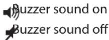
4. KVM buzzer status
5. Channel LOCK Indicator (Status STA)
L: Indicates that this channel is locked.
BLANK: Indicates that this channel is not locked.
Computer power on indicator (Status STA), OSD menu will update the flag automatically if the computer status changes.
A: Indicates that this computer is powered on and selectable.
BLANK: Indicates that this computer is not connected or powered on.
Channel scan indicator (Status STA)
S: This channel is marked for auto-scan.
BLANK: Indicates that this computer is not marked for auto-scan.
6. Current Active Channel Number
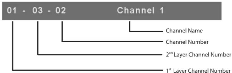
This indicates the current active channel number. The channel of the currently selected computer is displayed in the upper-right corner. If the active channel is in 2nd or 3rd cascade layer, the display string will be displayed in the format: XX-YY-ZZ. For example, 02-05-07 means the active channel is layer 1 - channel 2 to layer 2 - channel 5, and layer 3 - channel 7 is selected as the active channel.
7. Current Parent Channel Number
This indicates the parent channel of the cascade layer. The number at the upper-left corner below the KVM switch layer number shows the linked channel number of the upper layer (i.e. 8 indicates a link from channel 8 of the upper KVM switch). It will only be shown under the 2nd and 3rd cascade layer.
8. Page Up / Down Indicator
When using a 16-port KVM Switch, the information about channels 1 \~ 8 is displayed on the first page, and information for channels 9 \~ 16 is displayed on the second page. Since the channel information is divided onto two pages, the page down / up indicator is to remind you to switch to the first and second page using the
9. Function Control Menu
F1: Set Up: Basic set up menu
F2: Scan: Autoscan function
F3: Lock: Console lock function only available when F5 Security is enabled
F4: Rename: Rename the channel name
F5: Security: Security function and user authority settings
F6: Lock Port: PC port lock function (for administrator only)
Note: Please refer to page 32 to 41 for detailed information of the control functions.
Channel.Selection.in.OSD
Channel.Select.to.Computer
Use the
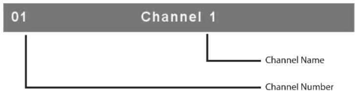
flowchart
graph TD
    A["01"] --> B["Channel 1"]
    B --> C["Channel Name"]
    B --> D["Channel Number"]
Figure.17.-.Channel.Banner.(Single.Layer)
Channel.Select.to.Cascade.Port
A plus mark (+) showing to the left side of the channel name indicates that the port is cascaded. Move the highlighted bar to this channel and then press
flowchart
graph TD
    A["01 - 03 - 02"] --> B["Channel 1"]
    B --> C["Channel Name"]
    B --> D["Channel Number"]
    B --> E["2ndLayer Channel Number"]
    B --> F["1stLayer Channel Number"]
Figure.18.-.Channel.Banner.(Cascade.Layer)
Return.from.Cascade.Port
Pressing
Setup.in.OSD:.
Press
![Setup Scan Mode: Select Scan Time: 005Sec. Banner Time: 005Sec. Position: Menu Banner Hotkey: Scroll Lock Sound: ON Language: English [En] ↑ ↓: Select ← +: Change Setting Esc: Save Return](/content/2026/05/857536/images/0c1c55cbf3f7c54c54c102636c6ae4d1f3661954c1895aece888c2fadbd5ea93.jpg)
Figure.19.-.OSD.Setup
Scan.Mode
Select: Scan the selected channels marked with S in the STA column on the OSD main menu.
PC.ON: Scan all PC channels which are powered on.
Scan.Time
The default scan time is 5 seconds. Scan time can be adjusted from 5 seconds to 90 seconds at 5 second increments.
Banner.Time
The default banner time is 5 seconds. It can be changed to 10 seconds, 15 seconds, or always on () .
Position
Menu: Use four arrow keys to move the OSD main menu to the desired position. Press.
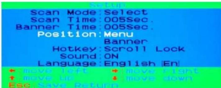
Figure.20.-Menu.Position.Setup
Banner:
Use four arrow keys to move the channel banner to the desired position. Press

Figure.21.-.Banner.Position.Setup
Hotkey
Scroll.Lock:
Num.Lock:
Cap.Lock:
Note: You can also change the leading hotkey via hotkey using
Sound
ON:.Buzzer sound is enabled. OFF: Buzzer sound is disabled
Note: You can also enable/disable buzzer sound via hotkey using
Language
English.(En)./.Deutsch.(De)./.Francais.(Fr), 3 languages are available.
Auto-Scan.in.OSD:.
Enter.the..Auto-scan.mode.in.OSD
Press
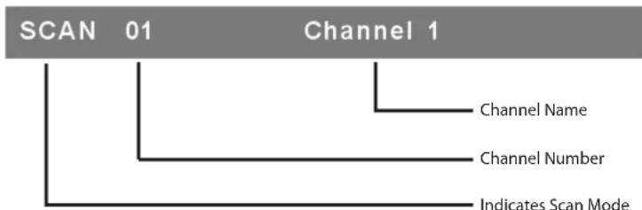
flowchart
graph TD
    A["SCAN 01"] --> B["Channel Name"]
    A --> C["Channel Number"]
    A --> D["Indicates Scan Mode"]
Figure.22.-.Auto.Scan.Banner
Note: You can also enter the auto-scan mode via hotkey using →
Exit.the.Auto-scan.Mode
Press any key on keyboard to STOP.the auto-scan function. The auto-scan banner will disappear when the scan stops.
Auto-scan.Mode
There are two auto-scan modes, please refer to the Setup.in.OSD.-.Scan.Mode section to set up the auto-scan mode.
- Scan all computers which are power on.
- Scan all computers which are marked for auto-scan.
Auto-scan.Time.Interval
The auto-scan time interval can be adjusted by pressing
Console.Lock.in.OSD:.
If the security mode is enabled in OSD mode (by pressing
Security
Mode
Protected
Figure.23.--Console.Lock.Banner
The KVM switch will be locked until an authorized user logs in.

Figure.24.-Unlock.Window
Note: You can also lock the console via hotkey using
Note: If you forget the password, the only way to disable the security function is to key in a universal password to unlock the KVM switch. You need to key in this password to unlock the KVM switch, and then you can re-initialize the system. Please contact your agency/distributor to obtain the universal password.
Channel.Rename:.
Select the channel to rename using the up/down arrow key and press.
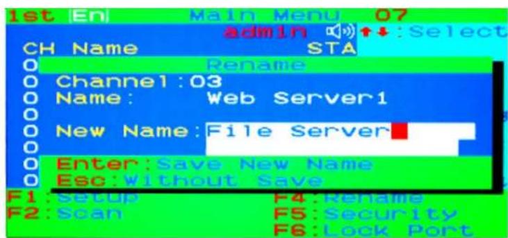
Figure.25.-Channel.Rename.Window
Security.Setup:
Security.mode.login
Press
Admin. Password :
Figure.26.-.Security.mode.login.window
The default administrator account is:
User.Name::admin
Password:.123456
After logging in, the security setup main window will be shown on the screen. Please select the security item via the
![Security Security Mode: OFF Admin/Password: ++++++ User Name: 1 2 3 Ch Name ABC DEF GHI 01 File Server [ ] [ ] [V] 02 Mail Server [ ] [V] [V] 03 Web Server1 [V] [ ] [ ] 04 RD Switch [V] [ ] [V] ↑ :Select + :ChangeSetting Esc:Save Return](/content/2026/05/857536/images/0601d5931218845dacdd9c8489a4c151f3624b28272e621d2f6a75b1cd887e65.jpg)
Figure.27.-.Security.Setup.Main.Window
Security.Mode
To change the security mode setting, please move the highlighted bar to Security.Mode, and press the
Change.Administrator.Password
To change the administrator password, move the highlighted bar to Admin/password, and press.the.
![Security Security Mode:OFF Admin/Password: + + + + + New Password: + + + + + Confirm Password: + + + Enter: Confirm Esc: Return 03 Web Server1 V [ ] [ ] 04 RD Switch V [ ] V ↑ ↓: Select + +: ChangeSetting Esc: Save. Return](/content/2026/05/857536/images/2a77d8e04b09939bee237c7881127c48f8ed143548420dccf3db535a5193ea4a.jpg)
Figure.28.-Administrator.Password.Setup.Window
Authorized.User.Setup
Up to 3 authorized users can manage the KVM switch. To change the user name and password, please move the highlighted bar to the user that you want to edit.
Press the
Please type in the new user name and password twice, then press
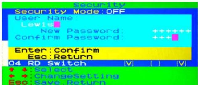
Figure.29.-User.Name.and.Password.Setup.Window
User.Authority.Setup
You can set up the authority level for each user. To set up access rights on each channel for each user, please move the highlighted bar to the channel, and press .then.<1>,<2> or <3>.
You are not required to setup the access right for the administrator since the administrator has full access on all channels.
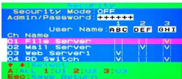
Figure.30.-.User.authority.setup.window
Lock.Port:.
Lock.the.Port
Only the administrator can lock the port. Please move the highlighted bar to the channel that you wish to lock, and press
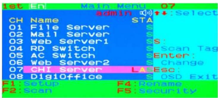
Figure.31.--Lock.the.port.from.the.OSD.main.window
Channel.Selection.of.the.Locked.Port
If anyone selects the locked port either by the front panel button or the hotkey, the system will enter into OSD mode automatically and will need an administrator to unlock the port.
Unlock.the.Port
The Port will be unlocked automatically when an administrator logs in. After the administrator logs in, the red L in the STA. column will disappear.
Sun. Keyboard. Emulation
The PS/2 keyboard can emulate the functions of the sun keyboard. The emulation mappings are listed in the table below:
To activate the SUN keyboard emulation on the PS/2 keyboard, you must press the
| Sun.MicrosystemsFunction.Key | PS/2. Keyboard | |
| Stop L_Win & L_Alt | ||
| Props L_Win & L_Ctrl | ||
| Compose L_Win & L_Shift | ||
| Front L_Win & F1 | ||
| Open L_Win & F2 | ||
| Find L_Win & F3 | ||
| Again L_Win & F4 | ||
| Undo L_Win & F5 | ||
| Copy | L_Win & F6 | |
| Paste L_Win & F7 | ||
| Cut | L_Win & F8 | |
| Help | L_Win & F11 | |
| Power | L_Win & F12 | |
| Mute | L_Win & 1 | |
| Volume Down | L_Win & 2 | |
| Volume Up | L_Win & 3 | |
Firmware Upgrade Procedures
The KVM switch provides the firmware upgrade for the following functions:
- USB console: Update for USB console keyboard/mouse compatibility. The firmware filename for USB console is like Dlink_KVM_Vxxx_bx.USB
- PS/2 console: Update for PS/2 console keyboard/mouse compatibility. The firmware filename for PS/2 console is like Dlink_KVM_Vxxx_bx.PS2.
- OSD: Update for on-screen-display functions. The firmware filename for OSD is like Dlink_KVM_Vxxx_bx.OSD.
To update the firmware, please follow the instructions below:
- Disconnects all the KVM cables between the switch and the computers.
- Disconnects the keyboard and mouse plugged on the KVM Switch.
- Disconnects the VGA cable between the KVM switch and the monitor.
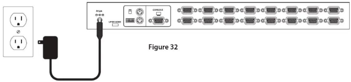
- Connect the DC 5V adapter to your power outlet and the KVM switch.
- Insert the CD-ROM into your CD Drive. Click on Install Utility from the autorun menu. The Firmware update utility window will appear on the screen.
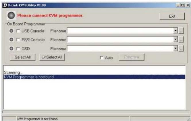
Figure 33
- Use the mini-USB cable to connect the firmware upgrade port of the KVM switch and the USB port of your computer.
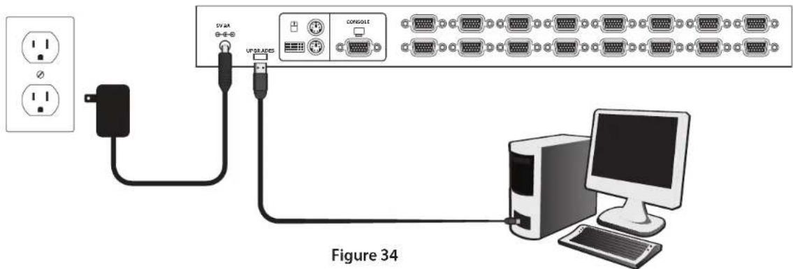
- The utility will scan the KVM programmer automatically.
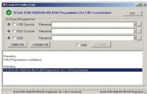
Figure 35
- Select USB console, PS/2 console or OSD for the firmware upgrade. Then, click the file browsing button to select the firmware file to update.
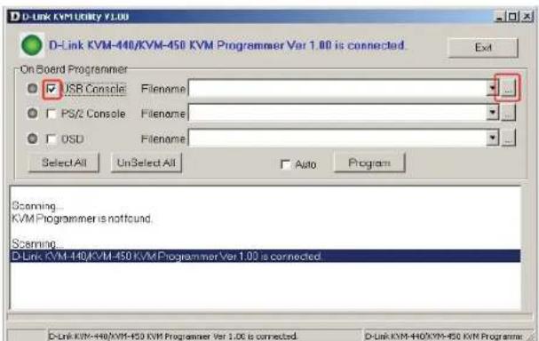
Figure 36
9. Select the firmware file to update.
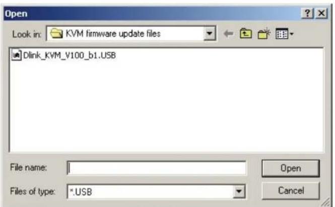
Figure 37
10. Click the "Program" button to start firmware programming.
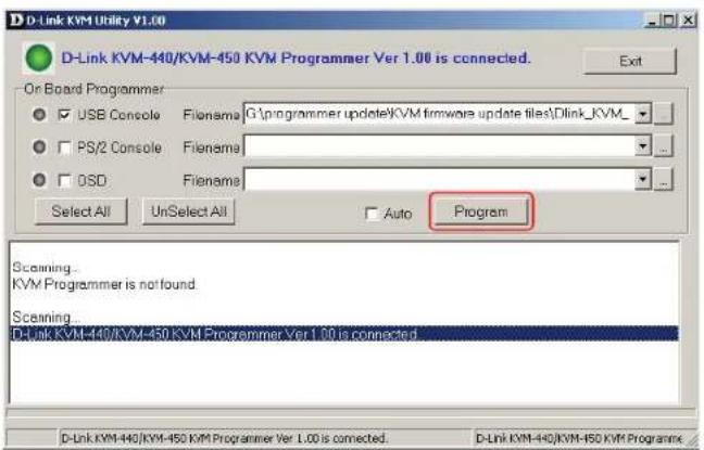
Figure 38
- A status bar is shown below the status window to indicate the update progress
![D-Link KVM Utility V1.00 Programming... On Board Programmer USB Console Filename: C:\programmer update\KVM firmware update files\Dink_KVM_ PS/Z Console Filename: OSO Filename: Select AI UnSelect AI Auto Program Scanning... KVM Programmer is not found. Scanning... D-Link KVM-440/KVM-450 KVM Programmer Ver 1.00 is connected. Target: USB Console File: G:\programmer update\KVM firmware update files\Dink_KVM_V130_b! US3 Programming... 05 Programming block [50]... D-Link KVM-440/KVM-450 KVM Programmer](/content/2026/05/857536/images/0d75512c3969ff37da0f261f00f495576440bac6b34bf1c62a67c9a400236d17.jpg)
Figure 39
- The firmware is updated successfully.

Figure 40
- Unplug the power adapter for a moment, and plug it back in to restart the device.
Troubleshooting
| SymptomPossible | .CauseRecommended.Solution | |
| Keyboard and/or Mouse do not work properly | • Keyboard and/or Mouse need to be reset. | • Unplug the cables from the console port(s), and then plug them back in. |
| • Failed connection to the computer. | • Check the cable connection between the switch and the computers and make sure they are connected properly. | |
| • KVM Switch needs to be reset. • Power off all connected devices and then power them up again. | ||
| Cascade chaining does not work | • Incorrect configuration or improper installation procedure | • Make sure the console port of the Slave KVM Switch is connected to the Master's PC port. Don't power on the slave KVM Switch before connecting it to the Master. Please refer to the Cascade.Chaining.Section. |
| Double OSD images under cascade chaining | • Failed Cascade Chaining connection. | • Make sure the cable between the Master KMV switch and the slave KVM switch is connected correctly. |
| • Improper Installation procedure | • Make sure the console port of the Slave KVM Switch is connected to the Master's PC port. Don't power on the slave KVM Switch before connecting it to the Master. Please refer to the Cascade.Chaining.Section. | |
| OSD menu is not displayed in the correct position | • The OSD menu has fixed resolution and its size varies due to the changes of computer VGA resolution. | • Use.: Set/Position to move OSD menu and banner to the proper position. |
Contacting.Technical.Support
D-Link provides free technical support for customers within the United States and within Canada for the duration of the warranty period on this product. U.S. and Canadian customers can contact D-Link technical support through our web site or by phone.
Before you contact technical support, please have the following ready:
- Model number of the product (e.g. KVM-440/450)
- Hardware Revision (located on the label on the bottom of the switch (e.g. rev A1))
- Serial Number (s/n number located on the label on the bottom of the switch).
You can find software updates and user documentation on the D-Link website as well as frequently asked questions and answers to technical issues.
For customers within the United States:
Phone Support:
(877) 354-6555
Internet Support:
http://support.dlink.com
For customers within Canada:
Phone Support:
(800) 354-6560
Internet Support:
http://support.dlink.ca
Warranty
Subject to the terms and conditions set forth herein, D-Link Systems, Inc. ("D-Link") provides this Limited Warranty:
- Only to the person or entity that originally purchased the product from D-Link or its authorized reseller or distributor, and
- Only for products purchased and delivered within the fifty states of the United States, the District of Columbia, U.S. Possessions or Protectorates, U.S. Military Installations, or addresses with an APO or FPO.
Limited Warranty:
D-Link warrants that the hardware portion of the D-Link product described below ("Hardware") will be free from material defects in workmanship and materials under normal use from the date of original retail purchase of the product, for the period set forth below ("Warranty Period"), except as otherwise stated herein.
• Hardware (excluding power supplies): One (1) year
• Free Technical Support - Basic Installation: Ninety (90) days
The customer's sole and exclusive remedy and the entire liability of D-Link and its suppliers under this Limited Warranty will be, at D-Link's option, to repair or replace the defective Hardware during the Warranty Period at no charge to the original owner or to refund the actual purchase price paid. Any repair or replacement will be rendered by D-Link at an Authorized D-Link Service Office. The replacement hardware need not be new or have an identical make, model or part. D-Link may, at its option, replace the defective Hardware or any part thereof with any reconditioned product that D-Link reasonably determines is substantially equivalent (or superior) in all material respects to the defective Hardware. Repaired or replacement hardware will be warranted for the remainder of the original Warranty Period or ninety (90) days, whichever is longer, and is subject to the same limitations and exclusions. If a material defect is incapable of correction, or if D-Link determines that it is not practical to repair or replace the defective Hardware, the actual price paid by the original purchaser for the defective Hardware will be refunded by D-Link upon return to D-Link of the defective Hardware. All Hardware or part thereof that is replaced by D-Link, or for which the purchase price is refunded, shall become the property of D-Link upon replacement or refund.
Limited Software Warranty:
D-Link warrants that the software portion of the product ("Software") will substantially conform to D-Link's then current functional specifications for the Software, as set forth in the applicable documentation, from the date of original retail purchase of the Software for a period of ninety (90) days ("Software Warranty Period"), provided that the Software is properly installed on approved hardware and operated as contemplated in its documentation. D-Link further warrants that, during the Software Warranty Period, the magnetic media on which D-Link delivers the Software will be free of physical defects. The customer's sole and exclusive remedy and the entire liability of D-Link and its suppliers under this Limited Warranty will be, at D-Link's option, to replace the non-conforming Software (or defective media) with software that substantially conforms to D-Link's functional specifications for the Software or to refund the portion of the actual purchase price paid that is attributable to the Software. Except as otherwise agreed by D-Link in writing, the replacement Software is provided only to the original licensee, and is subject to the terms and conditions of the license granted by D-Link for the Software. Replacement Software will be warranted for the remainder of the original Warranty Period and is subject to the same limitations and exclusions. If a material non-conformance is incapable of correction, or if D-Link determines in its sole discretion that it is not practical to replace the non-conforming Software, the price paid by the original licensee for the non-conforming Software will be refunded by D-Link; provided that the non-conforming Software (and all copies thereof) is first returned to D-Link. The license granted respecting any Software for which a refund is given automatically terminates.
Non-Applicability of Warranty:
The Limited Warranty provided hereunder for Hardware and Software portions of D-Link's products will not be applied to and does not cover any refurbished product and any product purchased through the inventory clearance or liquidation sale or other sales in which D-Link, the sellers, or the liquidators expressly disclaim their warranty obligation pertaining to the product and in that case, the product is being sold "As-ls" without any warranty whatsoever including, without limitation, the Limited Warranty as described herein, notwithstanding anything stated herein to the contrary.
Submitting A Claim:
The customer shall return the product to the original purchase point based on its return policy. In case the return policy period has expired and the product is within warranty, the customer shall submit a claim to D-Link as outlined below:
- The customer must submit with the product as part of the claim a written description of the Hardware defect or Software nonconformance in sufficient detail to allow D-Link to confirm the same, along with proof of purchase of the product (such as a copy of the dated purchase invoice for the product) if the product is not registered.
-
The customer must obtain a Case ID Number from D-Link Technical Support at 1-877-354-6555, who will attempt to assist the customer in resolving any suspected defects with the product. If the product is considered defective, the customer must obtain a Return Material Authorization ("RMA") number by completing the RMA form and entering the assigned Case ID Number at https://rma.dlink.com/.
-
After an RMA number is issued, the defective product must be packaged securely in the original or other suitable shipping package to ensure that it will not be damaged in transit, and the RMA number must be prominently marked on the outside of the package. Do not include any manuals or accessories in the shipping package. D-Link will only replace the defective portion of the product and will not ship back any accessories.
- The customer is responsible for all in-bound shipping charges to D-Link. No Cash on Delivery ("COD") is allowed. Products sent COD will either be rejected by D-Link or become the property of D-Link. Products shall be fully insured by the customer and shipped to D-Link Systems, Inc., 17595 Mt. Herrmann, Fountain Valley, CA 92708. D-Link will not be held responsible for any packages that are lost in transit to D-Link. The repaired or replaced packages will be shipped to the customer via UPS Ground or any common carrier selected by D-Link. Return shipping charges shall be prepaid by D-Link if you use an address in the United States, otherwise we will ship the product to you freight collect. Expedited shipping is available upon request and provided shipping charges are prepaid by the customer. D-Link may reject or return any product that is not packaged and shipped in strict compliance with the foregoing requirements, or for which an RMA number is not visible from the outside of the package. The product owner agrees to pay D-Link's reasonable handling and return shipping charges for any product that is not packaged and shipped in accordance with the foregoing requirements, or that is determined by D-Link not to be defective or non-conforming.
What Is Not Covered:
The Limited Warranty provided herein by D-Link does not cover:
Products that, in D-Link's judgment, have been subjected to abuse, accident, alteration, modification, tampering, negligence, misuse, faulty installation, lack of reasonable care, repair or service in any way that is not contemplated in the documentation for the product, or if the model or serial number has been altered, tampered with, defaced or removed; Initial installation, installation and removal of the product for repair, and shipping costs; Operational adjustments covered in the operating manual for the product, and normal maintenance; Damage that occurs in shipment, due to act of God, failures due to power surge, and cosmetic damage; Any hardware, software, firmware or other products or services provided by anyone other than D-Link; and Products that have been purchased from inventory clearance or liquidation sales or other sales in which D-Link, the sellers, or the liquidators expressly disclaim their warranty obligation pertaining to the product.
While necessary maintenance or repairs on your Product can be performed by any company, we recommend that you use only an Authorized D-Link Service Office. Improper or incorrectly performed maintenance or repair voids this Limited Warranty.
Disclaimer of Other Warranties:
EXCEPT FOR THE LIMITED WARRANTY SPECIFIED HEREIN, THE PRODUCT IS PROVIDED "AS-IS" WITHOUT ANY WARRANTY OF ANY KIND WHATSOEVER INCLUDING, WITHOUT LIMITATION, ANY WARRANTY OF MERCHANTABILITY, FITNESS FOR A PARTICULAR PURPOSE AND NON-INFRINGEMENT.
IF ANY IMPLIED WARRANTY CANNOT BE DISCLAIMED IN ANY TERRITORY WHERE A PRODUCT IS SOLD, THE DURATION OF SUCH IMPLIED WARRANTY SHALL BE LIMITED TO THE DURATION OF THE APPLICABLE WARRANTY PERIOD SET FORTH ABOVE. EXCEPT AS EXPRESSLY COVERED UNDER THE LIMITED WARRANTY PROVIDED HEREIN, THE ENTIRE RISK AS TO THE QUALITY, SELECTION AND PERFORMANCE OF THE PRODUCT IS WITH THE PURCHASER OF THE PRODUCT.
Limitation of Liability:
TO THE MAXIMUM EXTENT PERMITTED BY LAW, D-LINK IS NOT LIABLE UNDER ANY CONTRACT, NEGLIGENCE, STRICT LIABILITY OR OTHER LEGAL OR EQUITABLE THEORY FOR ANY LOSS OF USE OF THE PRODUCT, INCONVENIENCE OR DAMAGES OF ANY CHARACTER, WHETHER DIRECT, SPECIAL, INCIDENTAL OR CONSEQUENTIAL (INCLUDING, BUT NOT LIMITED TO, DAMAGES FOR LOSS OF GOODWILL, LOSS OF REVENUE OR PROFIT, WORK STOPPAGE, COMPUTER FAILURE OR MALFUNCTION, FAILURE OF OTHER EQUIPMENT OR COMPUTER PROGRAMS TO WHICH D-LINK'S PRODUCT IS CONNECTED WITH, LOSS OF INFORMATION OR DATA CONTAINED IN, STORED ON, OR INTEGRATED WITH ANY PRODUCT RETURNED TO D-LINK FOR WARRANTY SERVICE) RESULTING FROM THE USE OF THE PRODUCT, RELATING TO WARRANTY SERVICE, OR ARISING OUT OF ANY BREACH OF THIS LIMITED WARRANTY, EVEN IF D-LINK HAS BEEN ADVISED OF THE POSSIBILITY OF SUCH DAMAGES. THE SOLE REMEDY FOR A BREACH OF THE FOREGOING LIMITED WARRANTY IS REPAIR, REPLACEMENT OR REFUND OF THE DEFECTIVE OR NONCONFORMING PRODUCT. THE MAXIMUM LIABILITY OF D-LINK UNDER THIS WARRANTY IS LIMITED TO THE PURCHASE PRICE OF THE PRODUCT COVERED BY THE WARRANTY. THE FOREGOING EXPRESS WRITTEN WARRANTIES AND REMEDIES ARE EXCLUSIVE AND ARE IN LIEU OF ANY OTHER WARRANTIES OR REMEDIES, EXPRESS, IMPLIED OR STATUTORY.
Governing Law:
This Limited Warranty shall be governed by the laws of the State of California. Some states do not allow exclusion or limitation of incidental or consequential damages, or limitations on how long an implied warranty lasts, so the foregoing limitations and exclusions may not apply. This Limited Warranty provides specific legal rights and you may also have other rights which vary from state to state.
Trademarks:
D-Link is a registered trademark of D-Link Systems, Inc. Other trademarks or registered trademarks are the property of their respective owners.
Copyright Statement:
No part of this publication or documentation accompanying this product may be reproduced in any form or by any means or used to make any derivative such as translation, transformation, or adaptation without permission from D-Link Corporation/D-Link Systems, Inc., as stipulated by the United States Copyright Act of 1976 and any amendments thereto. Contents are subject to change without prior notice.
Copyright ©2011 by D-Link Corporation/D-Link Systems, Inc. All rights reserved.
CE Mark Warning:
This is a Class B product. In a domestic environment, this product may cause radio interference, in which case the user may be required to take adequate measures.
FCC Statement:
This equipment has been tested and found to comply with the limits for a Class B digital device, pursuant to part 15 of the FCC Rules. These limits are designed to provide reasonable protection against harmful interference in a residential installation. This equipment generates, uses, and can radiate radio frequency energy and, if not installed and used in accordance with the instructions, may cause harmful interference to radio communication. However, there is no guarantee that interference will not occur in a particular installation. If this equipment does cause harmful interference to radio or television reception, which can be determined by turning the equipment off and on, the user is encouraged to try to correct the interference by one or more of the following measures:
- Reorient or relocate the receiving antenna.
- Increase the separation between the equipment and receiver.
- Connect the equipment into an outlet on a circuit different from that to which the receiver is connected.
- Consult the dealer or an experienced radio/TV technician for help.
For detailed warranty information applicable to products purchased outside the United States, please contact the corresponding local D-Link office.
Registration
Register your product online at registration.dlink.com

natural_image
Woman in red dress using a laptop on a white sofa (no visible text or symbols)Product registration is entirely voluntary and failure to complete or return this form will not diminish your warranty rights.
Version 1.0
July 6, 2011
- Building Networks for People
- PS2/USB Combo KVM Switch
- User Manual
- Business Class Networking
- Table of Contents
- Introduction
- Package.Contents
- System.Requirements
- •.Console
- •.Computer.or.Server
- •.Cables
- Features
- Installation Front.View
- Rear.View
- Single.Stage.Installation.
- Precautions
- Console.Connection
- System.Connections
- Cascade.Chaining
- Initial.Plug-in.Process:
- Hot.plugging.and.hot swapping:
- Operation
- Button Operation
- Hotkey Operation
- OSD Operation
- Hot Key Operation Call OSD Menu
- Leading Hotkey Select
- Channel.Select.-.Single.KVM
- Specific.Channel.Selection
- Arrow.Key.Channel.Shift.Function
- .Channel.Shift.Function
- Channel.Select.-.Cascade.Chain.Layer
- Enable./.Disable.Buzzer.Sound
- Auto-Scan.Function
- Enter.the.Auto-scan.mode
- Exit.the.Auto-scan.mode
- Auto-scan.Mode.Options
- Auto-scan.Time.Interval
- Console Lock Function
- OSD Operation OSD Main Menu
- KVM Switch layer Number
- Channel Name
- Logged-in User Name
- KVM buzzer status
- Channel LOCK Indicator (Status STA)
- Channel scan indicator (Status STA)
- Current Active Channel Number
- Current Parent Channel Number
- Page Up / Down Indicator
- Function Control Menu
- Channel.Selection.in.OSD
- Channel.Select.to.Computer
- Channel.Select.to.Cascade.Port
- Return.from.Cascade.Port
- Setup.in.OSD:.
- Scan.Mode
- Scan.Time
- Banner.Time
- Position
- Banner:
- Hotkey
- Sound
- Language
- Auto-Scan.in.OSD:.
- Enter.the..Auto-scan.mode.in.OSD
- Auto-scan.Mode
- Console.Lock.in.OSD:.
- Channel.Rename:.
- Security.Setup:
- Security.mode.login
- Admin. Password :
- Security.Mode
- Change.Administrator.Password
- Authorized.User.Setup
- User.Authority.Setup
- Lock.Port:.
- Lock.the.Port
- Channel.Selection.of.the.Locked.Port
- Unlock.the.Port
- Sun. Keyboard. Emulation
- Firmware Upgrade Procedures
- Select the firmware file to update.
- Click the "Program" button to start firmware programming.
- Contacting.Technical.Support
- For customers within the United States:
- Phone Support:
- Internet Support:
- For customers within Canada:
- Warranty
- Limited Warranty:
- Limited Software Warranty:
- Non-Applicability of Warranty:
- Submitting A Claim:
- What Is Not Covered:
- Disclaimer of Other Warranties:
- Limitation of Liability:
- Governing Law:
- Trademarks:
- Copyright Statement:
- CE Mark Warning:
- FCC Statement:
- Registration
Brand : D-LINK
Model : KVM-440
Category : Computer Accessories