
HD7698 - Uncategorized Winegard - Free user manual and instructions
Find the device manual for free HD7698 Winegard in PDF.


| Product Type | Outdoor TV Antenna |
| Brand | Winegard |
| Model | HD7698 |
| Frequency Range | UHF 470–698 MHz, VHF 174–216 MHz |
| Gain | UHF 12–14 dBi, VHF 7–9 dBi |
| Maximum Range | Up to 60 miles |
| Dimensions | 72 x 14 x 3 inches |
| Weight | 8.5 lbs |
| Mounting Type | J-mount (included) |
| Cable Required | 75 ohm coaxial (not included) |
| Weather Resistance | UV-protected, weather-resistant |
| Number of Elements | 98 |
| Beam Width | 35 degrees |
| Pre-assembled | Yes |
| Warranty | 2 years |
| Care Instructions | Wipe with a damp cloth; avoid abrasive cleaners |
| Safety Precautions | Use proper grounding and lightning arrestor |
| Spare Parts Availability | Replacement elements and hardware available |
| Installation Location | Outdoor (roof, attic, or mast) |
Frequently Asked Questions - HD7698 Winegard
User questions about HD7698 Winegard
0 question about this device. Answer the ones you know or ask your own.
Ask a new question about this device
Download the instructions for your Uncategorized in PDF format for free! Find your manual HD7698 - Winegard and take your electronic device back in hand. On this page are published all the documents necessary for the use of your device. HD7698 by Winegard.
USER MANUAL HD7698 Winegard
Register your product at winegard.com/myantenna
For help, email help@winegard.com
WARNING:
Installation of the antennas near power lines is dangerous!
For your safety, follow the installation instructions.
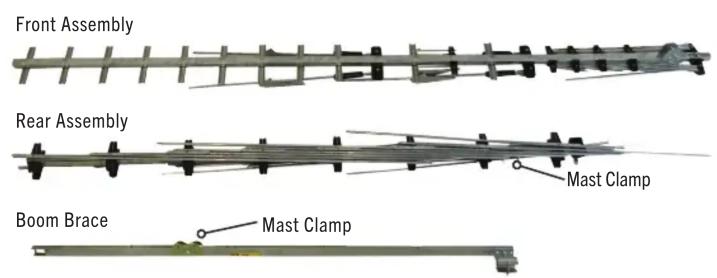
PARTS LIST
FIGURE 1

TOOLS REQUIRED
(not included)
Flat Head Screwdriver
Phillips Screwdriver
Crescent Wrench or Pliers
ASSEMBLY
STEP 1 - Contents of Package
A. Remove all parts from the box and compare to parts list to ensure nothing is missing and to become familiar with the part names. See figure1.
STEP 2 - Front Section
A. Stand front section up vertically and unfold all elements (in any order) until they snap into place.
B. Remove bolt, hex nut, and director element from the front section boom. See figure 2.
C. Unfold the UHF directors. See figure 2.
D. Set front section aside being careful not to bend the elements (laying it flat on the ground is the best position).
NOTE: Unfolding elements procedure is the same for both HD7698 & HD8200 antennas.
STEP 3 - Rear Section
A. Stand rear section up vertically with cartridge housing up and facing away from you.
B. Alternately unfold elements per figure 3 in direction of arrows until they lock into place in the black plastic blocks.
C. Spin the rear section around so the cartridge housing is now facing you. Unfold the remaining elements in the same order. See figure 3 for completely unfolded rear section.
FIGURE 2 - Front Assembly
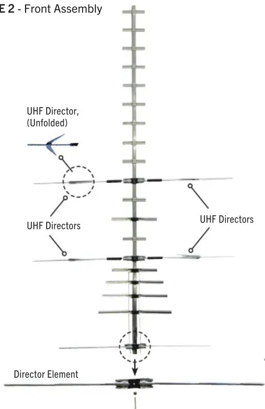
FIGURE 3 - Rear Assembly

flowchart
graph TD
    A["Cartridge Housing"] --> B["7 Down, Over & Up"]
    B --> C["6 Up"]
    C --> D["4 Up, Over & Down"]
    D --> E["3 Down"]
    E --> F["2 Up, Over & Down"]
    F --> G["1 Down"]
    style A fill:#f9f,stroke:#333
    style G fill:#f9f,stroke:#333
STEP 4 - Attaching Front Section to Rear Section
A. Slide the front boom into the rear boom making sure to feed the UHF phasing lines into the holes near the top of the cartridge housing, and into the slotted pegs inside the housing. See figure 4. When finished, the phasing lines will be resting in the slots of the pegs, but will not extend out the back side of the cartridge housing.
B. Reinstall the director element, bolt and nut. See figure 2.
STEP 5 - Cartridge Housing
WARNING: Be sure the phasing lines DO NOT touch the metal bracket or the antenna boom. See FIGURE 4.
A. Attach the cartridge housing cover so all 4 snaps are locked in place. Direction of the housing does not matter. See figure 5.
STEP 6 - Corner Reflector Assemblies
A. Unfold the elements on the corner reflector booms.
Element clip tips should point away from the open end of each boom. See figure 6.
B. Attach the corner reflector booms using the supplied nuts and bolts. See figure 6.
NOTE: The HD8200 antenna tuning stubs do not need to touch the boom.
STEP 7 - Boom Brace
A. Install the boom brace by first removing the bolts and hex nuts.
B. With the cartridge housing facing down, install the boom brace to the top corner reflector boom first, making sure the mast clamps are on the same side. See figure 7. Only finger tighten the bolt and hex nut.
C. Swing the other end of the boom brace down onto the rear section and insert the bolt and hex nut.
D. Tighten both bolts and nuts (on each end of the boom brace) securely.
FIGURE 4 - Front Section to Rear Section
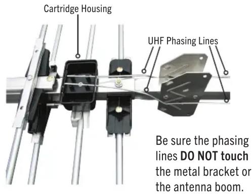
FIGURE 5 - Attach Cartridge Housing

FIGURE 6 - Corner Reflector Assemblies

FIGURE 7 - Boom Brace Installed

STEP 8 - Coaxial Cable
A. Slide the rubber boot over the end of the coaxial cable.
B. Attach the F-connector to the coaxial cable.
C. Attach the coaxial cable to the cartridge housing. See figure 8.
D. Slide the boot over the boot collar on the housing.
NOTE: If your coax cable has factory connectors on it, clip small end of boot off, so boot will slip over connector.
STEP 9 - Mounting Antenna to Mast
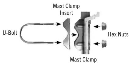
A. Loosen nuts on the main boom and boom brace mast clamps. See figure 9.
B. Slide both mast clamps over the mast, pointing the front of the antenna (small end) towards stations and tighten the boom brace mast clamp securely.
C. Let the main boom mast clamp slide down the mast until the boom brace supports the main boom. Tighten the main boom and brace mast clamps securely.
D. To prevent wind whipping, the 75 ohm coaxial cable downlead may be secured to the mast with tape or plastic wire ties.
Lightning Protection for TV Antenna & Set
A. Mount the lightning arrestor or 75 ohm coaxial grounding block as close as possible to where the 75 ohm coaxial cable downlead enters the house.
B. The ground wires for both the mast and the downlead should be copper or aluminum wire, number eight or larger.
C. The downlead wire from the antenna to the lightning arrestor and the mast ground wire should be secured to the house, spaced four to six feet apart.
NOTE: In the case of a “ground up” antenna installation, it may not be necessary to ground the mast if the mast extends four or more feet into the earth. Consult a TV serviceman for the proper depth in your location.
FIGURE 8 - Installing Coaxial Cable
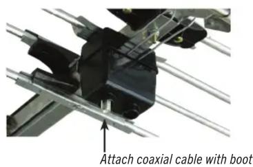
FIGURE 9 - Mast Clamp
LIGHTNING PROTECTION - Example of Antenna Grounding

NEC – Nation Electrical Code
90 DAY LIMITED WARRANTY
Winegard Company warrants this Winegard product against any defects in materials or workmanship within 90 (ninety) days from date of purchase. No warranty claim will be honored unless at the time the claim is made, you present proof of purchase to an authorized Winegard dealer (if unknown, please contact Winegard Company, 3000 Kirkwood Street, Burlington, IA 52601-2000, Telephone 800-288-8094).
Winegard Company (at its option) will either repair or replace the defective product at no charge to you. This warranty covers parts, but does not cover any costs incurred in removal, shipping or reinstallation of the product. This limited warranty does not apply if the product is damaged, deteriorates, malfunctions or fails from: misuse, improper installation, abuse, neglect, accident, tampering, modification of the product as originally manufactured by Winegard, usage not in accordance with product instructions or acts of nature such as damage caused by wind, lightning, ice or corrosive environments such as salt spray and acid rain.
The 90 Day Warranty is provided on the condition that the equipment is properly delivered with all handling and freight charges prepaid to your Winegard dealer for return to our factory for repair or replacement. Winegard dealers will arrange for the replacement or repair and return to you without charge the product which failed due to defective material or workmanship.
WINEGARD COMPANY WILL NOT ASSUME ANY LIABILITIES FOR ANY OTHER WARRANTIES, EXPRESS OR IMPLIED, MADE BY ANY OTHER PERSON.
ALL OTHER WARRANTIES WHETHER EXPRESS, IMPLIED OR STATUTORY INCLUDING WARRANTIES OF FITNESS FOR A PARTICULAR PURPOSE AND MERCHANTABILITY ARE LIMITED TO THE 90-DAY PERIOD OF THIS WARRANTY.
The foregoing shall be the sole and exclusive remedy of any person, whether in contract, tort or otherwise, and Winegard shall not be liable for incidental or consequential damage or commercial loss, or from any other loss or damage except as set forth above.
Some states do not allow limitations on how long an implied warranty lasts, or the exclusion of limitation of incidental or consequential damages, so the above limitations or exclusions may not apply to you.
This warranty gives you specific legal rights and you may also have other rights which vary from state to state.
Rev. 2/08

- PARTS LIST
- TOOLS REQUIRED
- ASSEMBLY
- STEP 1 - Contents of Package
- STEP 2 - Front Section
- STEP 3 - Rear Section
- STEP 4 - Attaching Front Section to Rear Section
- STEP 5 - Cartridge Housing
- WARNING: Be sure the phasing lines DO NOT touch the metal bracket or the antenna boom. See FIGURE 4.
- STEP 6 - Corner Reflector Assemblies
- NOTE: The HD8200 antenna tuning stubs do not need to touch the boom.
- STEP 7 - Boom Brace
- STEP 8 - Coaxial Cable
- STEP 9 - Mounting Antenna to Mast
- Lightning Protection for TV Antenna & Set
- DAY LIMITED WARRANTY
Brand : Winegard
Model : HD7698
Category : Uncategorized