
Compaq dx2308 - Unclassified HP - Free user manual and instructions
Find the device manual for free Compaq dx2308 HP in PDF.


| Brand | HP |
| Model | Compaq dx2308 |
| Product Type | Desktop PC |
| Processor | Intel Core 2 Duo (typical) |
| Memory (RAM) | 2 GB DDR2 (expandable to 4 GB) |
| Storage | 160 GB SATA HDD |
| Optical Drive | DVD±RW |
| Operating System | Windows Vista Business (pre-installed) |
| Dimensions (W x D x H) | 17.5 x 43.0 x 36.0 cm (6.9 x 16.9 x 14.2 in) |
| Weight | Approximately 10 kg (22 lb) |
| Power Supply | 300W ATX |
| Ports | USB 2.0 (6), VGA, DVI, Ethernet, Audio jacks |
| Expansion Slots | 2 PCI, 1 PCIe x16, 1 PCIe x1 |
| Security Features | Kensington lock slot, password protection in BIOS |
| Maintenance | Easy access to internal components; removable side panel |
| Cleaning | Use a soft, dry cloth; avoid liquids |
| Spare Parts Availability | RAM, HDD, power supply, optical drive (common standards) |
| Repairability | User-replaceable parts; no soldering required |
Frequently Asked Questions - Compaq dx2308 HP
User questions about Compaq dx2308 HP
0 question about this device. Answer the ones you know or ask your own.
Ask a new question about this device
Download the instructions for your Unclassified in PDF format for free! Find your manual Compaq dx2308 - HP and take your electronic device back in hand. On this page are published all the documents necessary for the use of your device. Compaq dx2308 by HP.
USER MANUAL Compaq dx2308 HP
Service Reference Guide
HP Compaq dx2300 and dx2308 Business PC
© Copyright 2007 Hewlett-Packard Development Company, L.P. The information contained herein is subject to change without notice.
Microsoft and Windows are trademarks of Microsoft Corporation in the U.S. and other countries.
The only warranties for HP products and services are set forth in the express warranty statements accompanying such products and services. Nothing herein should be construed as constituting an additional warranty. HP shall not be liable for technical or editorial errors or omissions contained herein.
This document contains proprietary information that is protected by copyright. No part of this document may be photocopied, reproduced, or translated to another language without the prior written consent of Hewlett-Packard Company.
Service Reference Guide
Business PCs
First Edition (February 2007)
Document Part Number: 443232-001
About This Book

WARNING! Text set off in this manner indicates that failure to follow directions could result in bodily harm or loss of life.

CAUTION: Text set off in this manner indicates that failure to follow directions could result in damage to equipment or loss of information.

NOTE: Text set off in this manner provides important supplemental information.
Table of contents
1 Install the Operating System
Installing or Upgrading Device Drivers .... 1
HP Backup and Recovery Manager 2
2 Computer Setup (F10) Utility
Computer Setup (F10) Utilities 3
Using Computer Setup (F10) Utilities 3
Computer Setup—System Information 4
Computer Setup—Main 6
Computer Setup—Advanced 7
Computer Setup—Boot 9
Computer Setup—PC Health 10
Computer Setup—Actions 10
Recovering the Configuration Settings 10
Backing Up the CMOS 11
Restoring the CMOS 11
3 HP Insight Diagnostics
HP Insight Diagnostics 13
Accessing HP Insight Diagnostics 13
Survey Tab 14
Test Tab 14
Status Tab 15
Log Tab 16
Help Tab 16
Saving and Printing Information in HP Insight Diagnostics 16
Downloading the Latest Version of HP Insight Diagnostics 17
4 Desktop Management
Remote System Installation 20
ROM Flash 21
Boot Block Emergency Recovery Mode 21
HP Web Site Support 22
Security 22
DriveLock 22
Using DriveLock 22
DriveLock Applications 23
Cable Lock Provision 23
Fault Notification and Recovery 23
Drive Protection System 23
Surge-Tolerant Power Supply 24
Thermal Sensor 24
5 Serial ATA (SATA) Drive Guidelines and Features
SATA Hard Drives 25
SATA Hard Drive Cables 25
SATA Data Cable 25
26
SMART ATA Drives 26
Hard Drive Capacities 26
6 Identifying the Chassis, Routine Care, and Disassembly Preparation
Chassis Designations 27
Microtower (MT) 27
Electrostatic Discharge Information 29
Generating Static 29
Preventing Electrostatic Damage to Equipment 29
Personal Grounding Methods and Equipment 30
Grounding the Work Area 30
Recommended Materials and Equipment 30
Operating Guidelines 32
Routine Care 32
General Cleaning Safety Precautions 32
Cleaning the Computer Case 32
Cleaning the Keyboard 33
Cleaning the Monitor 33
Cleaning the Mouse 34
Service Considerations 34
Power Supply Fan 34
Tools and Software Requirements 34
Screws 34
Cables and Connectors 35
Hard Drives 35
Lithium Coin Cell Battery 35
7 Removal and Replacement Procedures—Microtower (MT) Chassis
Preparation for Disassembly 37
Access Panel 38
Front Bezel 39
Front Drive Bezels 40
5.25" Drive Bezel Blank 40
Removing a 3.5" Drive Bezel Blank 41
Memory 42
DDR2-SDRAM DIMMs 42
Installing Memory Modules 42
Expansion Cards 44
Expansion Slot Cover Lock 44
PCI/PCIe Expansion Card 45
Cable Management 47
Cable Connections 48
Drives 49
Drive Positions 49
5.25" Drive 50
3.5" Drive 51
Removing a 3.5" Hard Drive 53
Front I/O Panel Housing Assembly 54
Power Switch Assembly 55
Speaker 56
Second Serial Port 57
System Fan 58
Heatsink 59
Processor 60
System Board 62
Battery 63
Type 1 Battery Holder 64
Type 2 Battery Holder 65
Type 3 Battery Holder 66
Power Supply 67
Appendix A Connector Pin Assignments
Keyboard 69
Mouse 69
Ethernet BNC 69
Ethernet RJ-45 70
Ethernet AUI 70
Parallel Interface 71
Serial Interface, Powered and Non-Powered 71
USB 71
Diskette Drive Power 72
Microphone 72
Headphone 72
Line-in Audio 72
Line-out Audio 72
External Infrared Transceiver 73
Monitor 73
Diskette Drive Standard Data Cable 74
24-Pin Power 74
24-Pin MicroFit Power 75
4-Pin Power (for CPU) 75
6-Pin Power (for CPU) 75
SATA Data and Power 76
PCI Express 76
PCI Express 77
DVI Connector 78
Appendix B Power Cord Set Requirements
General Requirements 81
Japanese Power Cord Requirements 81
Country-Specific Requirements 81
Appendix C Troubleshooting
Safety and Comfort 83
Helpful Hints 83
Solving General Problems 85
Solving Hardware Installation Problems 88
Interpreting Diagnostic Lights 89
Index 91
1 Install the Operating System

NOTE: If the computer was shipped with Microsoft Windows Vista loaded, you will be prompted to register the computer with HP Total Care before installing the operating system. You will see a brief movie followed by an online registration form. Fill out the form, click the Begin button, and follow the instructions on the screen.
If the computer was not shipped with a Microsoft operating system, some portions of this documentation do not apply. Refer to the operating system documentation and online Help for operating instructions.

CAUTION: Do not add optional hardware or third-party devices to your computer until the operating system is successfully installed. Doing so may cause errors and may prevent the operating system from installing properly. Once the automatic installation has begun, DO NOT TURN OFF THE COMPUTER UNTIL THE PROCESS IS COMPLETE. Turning off the computer during the installation process might damage the software that runs the computer or prevent its proper installation.

NOTE: Be sure there is a 10.2-cm (4-inch) clearance at the back of the unit and above the monitor to permit the required airflow.
The first time the computer is turned on, the operating system is automatically installed. This takes approximately 5 to 10 minutes, depending on the operating system being installed. Carefully read and follow the instructions that appear on the screen to complete the installation.

NOTE: If the computer shipped with more than one operating system language on the hard drive, the installation process could take up to 60 minutes.
Microsoft security updates are available on the Microsoft Web site.
Installing or Upgrading Device Drivers
When installing optional hardware devices after the operating system installation is complete, you must also install the drivers for each of the devices.
If prompted for the i386 directory, replace the path specification with C:\i386, or use the Browse button in the dialog box to locate the i386 folder. This action points the operating system to the appropriate drivers.
Obtain the latest support software, including support software for the operating system from http://www.hp.com/support. Select your country and language, select Download drivers and software, enter the model number of the computer, and press Enter.
HP Backup and Recovery Manager
The HP Backup and Recovery Manager is an easy-to-use, versatile application that is pre-loaded on each system and allows you to:
• create Recovery Points to back up the entire system incrementally • back up the entire system in a single hard archive • back up individual files
Backups can be scheduled to occur automatically at designated intervals, or they can be initiated manually. Recovery can be performed from the Recovery Partition on the hard drive or the Recovery Disc Set. The Recovery Disc Set includes the Restore Plus! CD, the Microsoft Operating System, and any Supplemental Software CDs.

NOTE: HP highly recommends that you create a Recovery Disc Set immediately before using the computer and schedule regular automatic Recovery Point backups.
To create the Recovery Disc Set:
- Click Start > HP Backup and Recovery > HP Backup and Recovery Manager to open the Backup and Recovery Wizard, then click Next.
- Select Create factory software recovery CDs or DVDs to recover the system.
- Follow the instructions in the wizard.
The HP Backup and Recovery Manager provides two basic recovery methods. The first, recovery of files and folders, operates in Windows. The second, PC Recovery, requires a reboot to the Recovery Partition or from the Recovery Disc Set. To reboot to the Recovery Partition, press F11 at startup when you see the message "Press F11 for Emergency Recovery."

NOTE: For more information on using HP Backup and Recovery Manager, refer to the HP Backup and Recovery Manager User Guide by selecting Start > HP Backup and Recovery > HP Backup and Recovery Manager Manual.
You can order a Recovery Disc Set from HP by calling the HP support center. Go to the following Web site, select your region, and click the Technical support after you buy link under the Call HP heading to obtain the support center telephone number for your region.
http://welcome.hp.com/country/us/en/wwcontact_us.html
2 Computer Setup (F10) Utility
Computer Setup (F10) Utilities
Use Computer Setup (F10) Utility to do the following:
• Change factory default settings. - Set the system date and time. - Set, view, change, or verify the system configuration, including settings for processor, graphics, memory, audio, storage, communications, and input devices. - Modify the boot order of bootable devices such as hard drives, diskette drives, optical drives, or USB flash media devices. • Restrict a device from booting the unit. • Run hard drive self-tests. • View CPU and system temperatures. - Enter the Asset Tag or property identification number assigned by the company to this computer. - Establish a supervisor password that controls access to Computer Setup (F10) Utility and the settings described in this section. - Secure integrated I/O functionality, including the serial, USB, or parallel ports, audio, or embedded NIC, so that they cannot be used until they are unsecured. - Enable or disable removable media boot ability. - Enable or disable legacy diskette write ability (when supported by hardware).
Using Computer Setup (F10) Utilities
Computer Setup can be accessed only by turning the computer on or restarting the system. To access the Computer Setup Utilities menu, complete the following steps:
- Turn on or restart the computer.
- As soon as the computer is turned on, press F10 when the monitor light turns green to enter Computer Setup. Press Enter to bypass the title screen, if necessary.

NOTE: If you do not press F10 at the appropriate time, you must restart the computer and again press F10 when the monitor light turns green to access the utility.
- The Computer Setup Utility screen is divided into menu headings and actions.
Five menu headings appear on the Computer Setup Utility screen:
• System Information - Main - Advanced - Boot - PC Health • Computer Setup-Actions
Use the arrow keys to select the appropriate heading, then press Enter. Use the arrow (up and down) keys to select the option you want, then press Enter. To return to the previous screen, press Esc.
4. To apply and save changes, press the F10 key.
If you have made changes that you do not want applied, press the F9 key to exit without saving.
To load optimized default values, press the F7 key.

CAUTION: Do NOT turn the computer power OFF while the ROM is saving the Computer Setup (F10) changes because the CMOS could become corrupted. It is safe to turn off the computer only after exiting the F10 Setup screen.
Table 2-1 Computer Setup (F10) Utility Main Menu
| Heading Table | |
| System Information | Computer Setup—System Information on page 4 |
| Main | Computer Setup—Main on page 6 |
| Advanced | Computer Setup—Advanced on page 7 |
| Boot | Computer Setup—Boot on page 9 |
| PC Health | Computer Setup—PC Health on page 10 |
| Exit | Computer Setup—Actions on page 10 |
Computer Setup—System Information

NOTE: Support for specific Computer Setup options may vary depending on the hardware configuration.
Table 2-2 Computer Setup—System Information
| Option Description | |
| Product Name | (view only) |
| SKU Number | (view only) |
| Processor Type | (view only) |
| Processor Speed | (view only) |
| System ROM | (view only) |
| Cache Size | (view only) |
| Memory Size | (view only) |
| Integrated MAC | (view only) |
| UUID | (view only) |
| System Serial # | (view only) |
| Asset Tracking Number | (view only) |

NOTE: Support for specific Computer Setup options may vary depending on the hardware configuration.
Table 2-3 Computer Setup—Main
| Option Description | |
| Date (mm:dd:yy) | Allows you to set system date. |
| Time (hh:mm:ss) | Allows you to set system time. |
| SATA Port 1 | For each, allows you to: |
| SATA Port 2 | run HDD self-test for selected channel: |
| SATA Port 3 | SMART Status Check |
| SATA Port 4 | HDD Short Self-TestHDD Extended Self-Testauto-detect HDD size and headset extended IDE drive on selected channel to:NoneAutoset access mode on selected channel to:LargeAutoview:FirmwareCapacityCylinderHeadPrecompLanding ZoneSector |
| Onboard FDC Controller | Disables/enables the floppy disk controller. |
| Drive A | Allows you to set Drive A to:None1.44M, 3.5 in. |
| Halt On | Allows you to set POST error behavior to:All ErrorsNo ErrorsAll but KeyboardAll but DisketteAll but Diskette/Keyboard |
| POST Delay | Allows you to set a POST delay to:0 seconds5 seconds10 seconds15 seconds30 seconds |
Computer Setup—Advanced

NOTE: Support for specific Computer Setup options may vary depending on the hardware configuration.
Table 2-4 Computer Setup—Advanced
| Option Description | |
| Execute Disable Bit | Disables/enables hardware DEP functionality. |
| MAX DVMT Allocation | Specify the size of DVMT/system memory to allocate for video memory:64MB128MB224MB |
| Init Display First(VGA Setting) | Allows you to select the primary display device:PCI SlotOnChipVGAPCIEx |
| Onboard HD Audio | Disables/enables onboard HD audio. |
| OnChip USB Controller | Disables/enables USB controller. |
| USB Legacy Support | Disables/enables USB legacy support function (USB keyboard, USB mouse, and USB flash media). |
| Onboard LAN | Disables/enables onboard LAN controller. |
| Onboard LAN Boot ROM | Disables/enables the boot ROM of the onboard LAN chip. |
| Onboard Serial Port 1 | Allows you to select a setting for the onboard serial port:Disabled |
| Onboard Serial Port 2 | 3F8/IRQ42F8/IRQ33E8/IRQ42E8/IRQ3 |
| Onboard Parallel Port | Allows you to select a setting for the onboard parallel port:Disabled378/IRQ7278/IRQ53BC/IRQ7 |
| Parallel Port Mode | Allows you to select parallel port mode:SPEPPEPECPECP+EPPNormal |
| After AC Power Loss | Allows you to select system power loss behavior:OnOffLast State |
| Wake on PCI Device from S5 | Disables/enables waking up from S5 by PCI device. |
| RTC Alarm Resume | Disables/enables RTC (real-time clock) alarm. |
| Date (of Month) | If RTC Alarm Resume is enabled, allows you to select the day of the month for resumption of RTC alarm.(Set to 0 for every day.) |
| Resume Time (hh:mm:ss) | If RTC Alarm Resume is enabled, allows you to select what time the RTC alarm will resume. |

NOTE: Support for specific Computer Setup options may vary depending on the hardware configuration.
Table 2-5 Computer Setup—Boot
| Option Description | |
| Device Boot Disabling | Allows disabling of bootable device groups. Choose from:NoneUSBInternal ODDInternal FDDUSB+ODD+FDD |
| F9 Boot Menu | Disables/enables F9 Boot Menu. |
| Removable Device Boot Seq. | Allows you to specify the order of attached removable devices (such as Floppy Discs or USB FDD). The first drive in the order has priority in the boot sequence and is recognized as drive A. |
| Hard Disk Boot Seq. | Allows you to specify the order of attached hard drive devices (such as USB HDD storage, USB2 Drive Key, or USB flash media). The first drive in the order has priority in the boot sequence and is recognized as drive C (if any devices are attached). |
| Optical Drive Boot Seq. | Allows you to specify the order in which attached optical drives (including USB ODD) are checked for a bootable operating system image. |
| Network Boot Seq. | Allows you to specify the order in which network devices (including UP NIC cards) are checked for a bootable operating system image. |
| First Boot DeviceSecond Boot DeviceThird Boot DeviceFourth Boot Device | Allows you to specify which devices will boot first, second, third, and fourth or to disable any of the four:RemovableHard DiskCDROMNetworkDisabled[25w7]NOTE:MS-DOS drive lettering assignments may not apply after a non-MS-DOS operating system has started. |
| Set Supervisor Password | Allows you to establish a password to control access to Computer Setup. |
| Set User Password | Allows you to establish a password to control access to the computer. (Supervisor password must be set before you can set a User password.) |
| Security Option | Allows you to set the security option to Setup or System so that the password is required every time the system boots or only when entering Computer Setup. |
| BIOS Write Protection | Enable to prevent BIOS from being updated, disable to allow update. |
Computer Setup—PC Health

NOTE: Support for specific Computer Setup options may vary depending on the hardware configuration.
Table 2-6 Computer Setup—PC Health
| Option Description | |
| System Fan Fail Check | Disables/enables system fan detection during POST. |
| Smart Fan Function | Disables/enables smart fan functionality. |
| Current CPU Temperature | (view only) |
| Current System Temperature | (view only) |
| Current CPU Fan Speed | (view only) |
| Current System Fan Speed | (view only) |
| Vcore | (view only) |
| 12V | (view only) |
| 5V | (view only) |
| VCC (V) | (view only) |
| VBAT (V) | (view only) |
| 5VSB (V) | (view only) |
Computer Setup—Actions
Table 2-7 Computer Setup—Actions
| Option Description | |
| Save and Exit Setup | Allows you to save current settings and exit Computer Setup. |
| Exit Without Saving | Allows you to exit Computer Setup without saving changes.. |
| Load Optimized Defaults | Allows you to reset Computer Setup to factory defaults. |
Recovering the Configuration Settings
Recovering the configuration settings established in the Computer Setup (F10) Utility requires that you first back up the settings before a recovery is needed.
The CMOS Save/Load utility can be found at http://www.hp.com under the Software & Driver Downloads for your specific model. Download the firmware files into a folder on a removable storage device. It is recommended that you save any modified computer configuration settings to a diskette, a USB flash media device, or a diskette-like device (a storage device set to emulate a diskette drive) and save the diskette or device for possible future use.
Backing Up the CMOS
- Make sure the computer to be backed up is turned on. Connect the removable storage to the computer.
- Boot to DOS.
- Type N:\folder\BIOS.exe SAVE:ABC001.DAT (where N is the drive letter of the removable storage) to save the CMOS setting to the removable storage device.
Restoring the CMOS
- Make sure the target computer is turned on. Connect the removable storage to the target computer.
- Boot to DOS.
- Type N:\folder\BIOS.exe LOAD:ABC001.DAT (where N is the drive letter of the removable storage) to load the custom CMOS setting onto the target system.
3 HP Insight Diagnostics
HP Insight Diagnostics

NOTE: HP Insight Diagnostics is included on CD with some computer models only.
The HP Insight Diagnostics utility allows you to view information about the hardware configuration of the computer and perform hardware diagnostic tests on the subsystems of the computer. The utility simplifies the process of effectively identifying, diagnosing, and isolating hardware issues.
The Survey tab is displayed when you invoke HP Insight Diagnostics. This tab shows the current configuration of the computer. From the Survey tab, there is access to several categories of information about the computer. Other tabs provide additional information, including diagnostic test options and test results. The information in each screen of the utility can be saved as an html file and stored on a diskette or USB HP Drive Key.
Use HP Insight Diagnostics to determine if all the devices installed on the computer are recognized by the system and functioning properly. Running tests is optional but recommended after installing or connecting a new device.
You should run tests, save the test results, and print them so that you have printed reports available before placing a call to the Customer Support Center.

NOTE: Third party devices may not be detected by HP Insight Diagnostics.
Accessing HP Insight Diagnostics
You must boot to the Documentation and Diagnostics CD, as described in the steps below, to access HP Insight Diagnostics.
- While the computer is on, insert the Documentation and Diagnostics CD into an optical drive on the computer.
- Shut down the operating system and turn off the computer.
- Turn on the computer. The system will boot to the CD.

NOTE: If the system does not boot to the CD in the optical drive, you may need to change the boot order in the Computer Setup (F10) utility so that the system attempts to boot to the optical drive before booting to the hard drive. Refer to the Computer Setup (F10) Utility Guide on the Documentation and Diagnostics CD for more information.
- Select the appropriate language and click Continue.
- In the End User License Agreement page, click Agree if you agree with the terms. The HP Insight Diagnostics utility launches with the Survey tab displayed.
Survey Tab
The Survey tab displays important system configuration information.
In the View level field, you can select the Summary view to see limited configuration data or select the Advanced view to see all the data in the selected category.
In the Category field, you can select the following categories of information to display:
All—Gives a listing of all categories of information about the computer.
Overview—Gives you a listing of general information about the computer.
Architecture—Provides system BIOS and PCI device information.
Asset Control—Shows product name, asset tag, system serial number, and processor information.
Communication—Shows information about the computer parallel (LPT) and serial (COM) port settings, plus USB and network controller information.
Graphics—Shows information about the graphics controller of the computer.
Input Devices—Shows information about the keyboard, mouse, and other input devices connected to the computer.
Memory—Shows information about all memory in the computer. This includes memory slots on the system board and any memory modules installed.
Miscellaneous—Shows HP Insight Diagnostics version information, computer configuration memory (CMOS) information, system board data, and system management BIOS data.
Storage—Shows information about storage media connected to the computer. This list includes all fixed disks, diskette drives, and optical drives.
System—Shows information about the computer model, processor, chassis, and BIOS, plus internal speaker and PCI bus information.
Test Tab
The Test tab allows you to choose various parts of the system to test. You can also choose the type of test and testing mode.
There are three types of tests to choose from:
- Quick Test—Provides a predetermined script where a sample of each hardware component is exercised and requires no user intervention in either Unattended or Interactive mode.
- Complete Test—Provides a predetermined script where each hardware component is fully tested. There are more tests available in the Interactive mode, but these require user intervention.
- Custom Test—Provides the most flexibility in controlling the testing of a system. The Custom Test mode allows you to specifically select which devices, tests, and test parameters are run.
For each test type, there are two test modes to choose from:
- Interactive Mode—Provides maximum control over the testing process. The diagnostic software will prompt you for input during tests that require your interaction. You may also determine whether the test passed or failed.
- Unattended Mode—Does not display prompts and requires no interaction. If errors are found, they are displayed when testing is complete.
To begin testing:
- Select the Test tab.
- Select the tab for the type of test you want to run: Quick, Complete, or Custom.
- Select the Test Mode: Interactive or Unattended.
- Choose how you want the test to be executed, either Number of Loops or Total Test Time. When choosing to run the test over a specified number of loops, enter the number of loops to perform. If you desire to have the diagnostic test for a specified time period, enter the amount of time in minutes.
- If performing a Quick Test or Complete Test, select the device to be tested from the drop-down list. If performing a Custom Test, Click the Expand button and select the devices to be tested or click the Check All button to select all devices.
- Click the Begin Testing button at the bottom right corner of the screen to start the test. The Status tab, which allows you to monitor the progress of the test, is automatically displayed during the testing process. When the test is complete, the Status tab shows whether the device passed or failed.
- If errors are found, go to the Log tab and click the Error Log to display more detailed information and recommended actions.
Status Tab
The Status tab displays the status of the selected tests. The type of test executed (Quick, Complete, or Custom) is also displayed. The main progress bar displays the percent complete of the current set of tests. While testing is in progress, a Cancel Testing button is displayed for use if you want to cancel the test.
After testing has completed, the Cancel Testing button is replaced with a Retest button. The Retest button will retest the last set of tests executed. This enables you to re-run the set of tests without having to re-enter the data in the Test tab.
The Status tab also shows:
• The devices being tested • The test status (running, passed, or failed) of each device being tested • The overall test progress of all devices being tested • The test progress for each device being tested • The elapsed test times for each device being tested
Log Tab
The Log tab contains a Test Log tab and an Error Log tab.
The Test Log displays all tests that have been executed, the number of times of execution, the number of times failed, and the time it took to complete each test. The Clear Test Log button will clear the contents of the Test Log.
The Error Log displays the tests for devices that have failed during the diagnostic testing and includes the following columns of information.
• The Device section displays the device tested. • The Test section displays the type of test run. The Description section describes the error that the diagnostic test found. - The Recommended Repair will give a recommended action that should be performed to resolve the failed hardware. The Failed Count is the number of times the device has failed a test. - The Error Code provides a numerical code for the failure. The error codes are defined in the Help tab.
The Clear Error Log button will clear the contents of the Error Log.
Help Tab
On the Help tab contains an HP Insight Diagnostics tab, an Error Codes tab, and a Test Components tab.
The HP Insight Diagnostics tab contains help topics and includes search and index features.
The Error Codes tab provides a description of each numerical error code that may appear in the Error Log tab located on the Log tab. Each code has a corresponding error Message and a Recommended Repair action that should help solve the problem. To find an error code description quickly, enter the code in the box at the top of the tab and click the Find Error Codes button.
The Test Components tab displays low-level information on tests that are run.
Saving and Printing Information in HP Insight Diagnostics
You can save the information displayed in the HP Insight Diagnostics Survey and Log tabs to a diskette or a USB 2.0 HP Drive Key (64MB or higher). You cannot save to the hard drive. The system will automatically create an html file that has the same appearance as the information displayed on the screen.
- Insert a diskette or USB 2.0 HP Drive Key (capacity must be 64MB or higher). USB 1.0 Drive Keys are not supported.
- Click Save in the bottom right corner of the screen.
- Select Save to the floppy or Save to USB key.
- Enter a file name in the File Name box and click the Save button. An html file will be saved to the inserted diskette or USB HP Drive Key.

NOTE: Do not remove the diskette or USB key until you see a message indicating that the html file has been written to the media.
- Print the information from the storage device used to save it.

NOTE: To exit HP Insight Diagnostics, click Exit Diagnostics button in the bottom left corner of the screen then remove the Documentation and Diagnostics CD from the optical drive.
Downloading the Latest Version of HP Insight Diagnostics
- Go to http://www.hp.com.
- Click the Software & Driver Downloads link.
- Select your specific computer model.
- Select your OS.
- Click the Diagnostic link.
- Click HP Insight Diagnostics Offline Edition.
- Select a language and click Download.
- Enter your product number (for example, dc7700) in the text box and press the Enter key.

NOTE: The download includes instructions on how to create the bootable CD.
4 Desktop Management
Remote System Installation
Remote System Installation allows you to start and set up the system using the software and configuration information located on a network server by initiating the Preboot Execution Environment (PXE). The Remote System Installation feature is usually used as a system setup and configuration tool, and can be used for the following tasks:
• Formatting a hard drive - Deploying a software image on one or more new PCs • Remotely updating the system BIOS in flash ROM - Configuring the system BIOS settings
To initiate Remote System Installation, press F12 when the F12 = Network Service Boot message appears in the lower-right corner of the HP logo screen when the computer is booting up. Follow the instructions on the screen to continue the process. The default boot order is a BIOS configuration setting that can be changed to always attempt to PXE boot.
ROM Flash
The computer's BIOS is stored in a programmable flash ROM (read only memory). By establishing a setup password in the Computer Setup (F10) Utility, you can protect the ROM from being unintentionally updated or overwritten. This is important to ensure the operating integrity of the computer. Should you need or want to upgrade the BIOS, you may download the latest BIOS images from the HP driver and support page, http://www.hp.com/support/files.

CAUTION: For maximum ROM protection, be sure to establish a setup password. The setup password prevents unauthorized ROM upgrades. System Software Manager allows the system administrator to set the setup password on one or more PCs simultaneously. For more information, visit http://www.hp.com/go/ssm.
Boot Block Emergency Recovery Mode
Boot Block Emergency Recovery Mode permits system recovery in the unlikely event of a ROM flash failure. For example, if a power failure were to occur during a BIOS upgrade, the ROM flash would be incomplete. This would render the system BIOS unusable. The Boot Block is a flash-protected section of the ROM that contains code that checks for a valid system BIOS image when the system is turned on.
• If the system BIOS image is valid, the system starts normally. • If the system BIOS image is not valid, a failsafe Boot Block BIOS provides enough support to
- search removable media for BIOS image files. If an appropriate BIOS image file is found, it is automatically flashed into the ROM.
- start the system from bootable removable media that automatically invokes system BIOS upgrade utilities.
When an invalid system BIOS image is detected, the system power LED will blink red 8 times, one blink every second. Simultaneously, the speaker will beep 8 times. If the portion of the system ROM containing the video option ROM image is not corrupt, Boot Block Emergency Recovery Mode will be displayed on the screen.
To recover the system after it enters Boot Block Emergency Recovery Mode, complete the following steps:
- Turn off the power.
- Insert a diskette, CD, or USB flash device containing the desired BIOS image file in the root directory.

NOTE: The media must be formatted using the FAT12, FAT16, or FAT32 file system.
- Turn on the computer.
If no appropriate BIOS image file is found, the failsafe Boot Block BIOS will attempt to start the system from a bootable device. If no bootable device is found, you will be prompted to insert media containing a BIOS image file or BIOS upgrade utility.
If the system successfully reprograms the ROM, the system will automatically power off.
- Remove the removable media used to upgrade the BIOS.
- Turn the power on to restart the computer.
HP Web Site Support
HP engineers rigorously test and debug software developed by HP and third-party suppliers, and develop operating system specific support software, to ensure performance, compatibility, and reliability for HP computers.
When making the transition to new or revised operating systems, it is important to implement the support software designed for that operating system. If you plan to run a version of Microsoft Windows that is different from the version included with the computer, you must install corresponding device drivers and utilities to ensure that all features are supported and functioning properly.
HP has made the task of locating, accessing, evaluating, and installing the latest support software easier. You can download the software from http://www.hp.com/support.
The Web site contains the latest device drivers, utilities, and flashable ROM images needed to run the latest Microsoft Windows operating system on the HP computer.
Security
DriveLock
DriveLock is an industry-standard security feature that prevents unauthorized access to the data on ATA hard drives. DriveLock has been implemented as an extension to Computer Setup. It is only available when hard drives that support the ATA Security command set are detected. DriveLock is intended for HP customers for whom data security is the paramount concern. For such customers, the cost of the hard drive and the loss of the data stored on it is inconsequential when compared with the damage that could result from unauthorized access to its contents. In order to balance this level of security with the practical need to accommodate a forgotten password, the HP implementation of DriveLock employs a two-password security scheme. One password is intended to be set and used by a system administrator while the other is typically set and used by the end-user. There is no "back-door" that can be used to unlock the drive if both passwords are lost. Therefore, DriveLock is most safely used when the data contained on the hard drive is replicated on a corporate information system or is regularly backed up. In the event that both DriveLock passwords are lost, the hard drive is rendered unusable. For users who do not fit the previously defined customer profile, this may be an unacceptable risk. For users who do fit the customer profile, it may be a tolerable risk given the nature of the data stored on the hard drive.
Using DriveLock
When one or more hard drives that support the ATA Security command set are detected, the DriveLock option appears under the Security menu in Computer Setup. The user is presented with options to set the master password or to enable DriveLock. A user password must be provided in order to enable DriveLock. Since the initial configuration of DriveLock is typically performed by a system administrator, a master password should be set first. HP encourages system administrators to set a master password whether they plan to enable DriveLock or keep it disabled. This will give the administrator the ability to modify DriveLock settings if the drive is locked in the future. Once the master password is set, the system administrator may enable DriveLock or choose to keep it disabled.
If a locked hard drive is present, POST will require a password to unlock the device. If a power-on password is set and it matches the device's user password, POST will not prompt the user to re-enter the password. Otherwise, the user will be prompted to enter a DriveLock password. On a cold boot, either the master or the user password may be used. On a warm boot, enter the same password used to unlock the drive during the preceding cold-boot. Users will have two attempts to enter a correct password. On a cold boot, if neither attempt succeeds, POST will continue but the drive will remain inaccessible. On a
warm boot or restart from Windows, if neither attempt succeeds, POST will halt and the user will be instructed to cycle power.
DriveLock Applications
The most practical use of the DriveLock security feature is in a corporate environment. The system administrator would be responsible for configuring the hard drive which would involve, among other things, setting the DriveLock master password and a temporary user password. In the event that the user forgets the user password or the equipment is passed on to another employee, the master password can always be used to reset the user password and regain access to the hard drive.
HP recommends that corporate system administrators who choose to enable DriveLock also establish a corporate policy for setting and maintaining master passwords. This should be done to prevent a situation where an employee intentionally or unintentionally sets both DriveLock passwords before leaving the company. In such a scenario, the hard drive would be rendered unusable and require replacement. Likewise, by not setting a master password, system administrators may find themselves locked out of a hard drive and unable to perform routine checks for unauthorized software, other asset control functions, and support.
For users with less stringent security requirements, HP does not recommend enabling DriveLock. Users in this category include personal users or users who do not maintain sensitive data on their hard drives as a common practice. For these users, the potential loss of a hard drive resulting from forgetting both passwords is much greater than the value of the data DriveLock has been designed to protect. Access to Computer Setup and DriveLock can be restricted through the Setup password. By specifying a Setup password and not giving it to end users, system administrators are able to restrict users from enabling DriveLock.
Cable Lock Provision
The rear panel of the computer accommodates a cable lock so that the computer can be physically secured to a work area.
For illustrated instructions, please see the Hardware Reference Guide on the Documentation and Diagnostics CD.
Fault Notification and Recovery
Fault Notification and Recovery features combine innovative hardware and software technology to prevent the loss of critical data and minimize unplanned downtime.
If the computer is connected to a network managed by HP Client Manager, the computer sends a fault notice to the network management application. With HP Client Manager Software, you can also remotely schedule diagnostics to automatically run on all managed PCs and create a summary report of failed tests.
Drive Protection System
The Drive Protection System (DPS) is a diagnostic tool built into the hard drives installed in some HP computers. DPS is designed to help diagnose problems that might result in unwarranted hard drive replacement.
When HP computers are built, each installed hard drive is tested using DPS, and a permanent record of key information is written onto the drive. Each time DPS is run, test results are written to the hard drive. You can use this information to help diagnose conditions that caused you to run the DPS software. Refer to the Troubleshooting Guide on the Documentation and Diagnostics CD for instructions on using DPS.
Surge-Tolerant Power Supply
An integrated surge-tolerant power supply provides greater reliability when the computer is hit with an unpredictable power surge. This power supply is rated to withstand a power surge of up to 2000 volts without incurring any system downtime or data loss.
Thermal Sensor
The thermal sensor is a hardware and software feature that tracks the internal temperature of the computer. This feature displays a warning message when the normal range is exceeded, which gives you time to take action before internal components are damaged or data is lost.
5 Serial ATA (SATA) Drive Guidelines and Features

NOTE: HP only supports the use of SATA hard drives on these models of computer. No Parallel ATA (PATA) drives are supported.
SATA Hard Drives
| Serial ATA Hard Drive Characteristics |
| Number of pins/conductors in data cable 7/7 |
| Number of pins in power cable 15 |
| Maximum data cable length 39.37 in (100 cm) |
| Data interface voltage differential 400-700 mV |
| Drive voltages 3.3 V, 5 V, 12 V |
| Jumpers for configuring drive N/A |
| Data transfer rate 3.0 Gb/s |
SATA Hard Drive Cables
SATA Data Cable
Always use an HP approved SATA 3.0 Gb/s cable as it is fully backwards compatible with the SATA 1.5 Gb/s drives.
Current HP desktop products ship with SATA 3.0 Gb/s hard drives.
SATA data cables are susceptible to damage if overflexed. Never crease a SATA data cable and never bend it tighter than a 30 mm (1.18 in) radius.
The SATA data cable is a thin, 7-pin cable designed to transmit data for only a single drive. See SATA Data and Power on page 76 for the pinout information.
SMART ATA Drives
The Self Monitoring Analysis and Recording Technology (SMART) ATA drives for the HP Personal Computers have built-in drive failure prediction that warns the user or network administrator of an impending failure or crash of the hard drive. The SMART drive tracks fault prediction and failure indication parameters such as reallocated sector count, spin retry count, and calibration retry count. If the drive determines that a failure is imminent, it generates a fault alert.
Hard Drive Capacities
The combination of the file system and the operating system used in the computer determines the maximum usable size of a drive partition. A drive partition is the largest segment of a drive that may be properly accessed by the operating system. A single hard drive may therefore be subdivided into a number of unique drive partitions in order to make use of all of its space.
Because of the differences in the way that drive sizes are calculated, the size reported by the operating system may differ from that marked on the hard drive or listed in the computer specification. Drive size calculations by drive manufacturers are bytes to the base 10 while calculations by Microsoft are bytes to the base 2.
| Drive/Partition Capacity Limits | ||||
| Maximum Size | ||||
| File System | Controller Type | Operating System | Partition | Drive |
| FAT 32 | ATA | Windows 2000/ XP | 32 GB | 2 TB |
| NTFS ATA Windows NT/2000/XP 2 TB 2 TB | ||||
6 Identifying the Chassis, Routine Care, and Disassembly Preparation
This chapter provides general service information for the computer. Adherence to the procedures and precautions described in this chapter is essential for proper service.

CAUTION: When the computer is plugged into an AC power source, voltage is always applied to the system board. You must disconnect the power cord from the power source before opening the computer to prevent system board or component damage.
Chassis Designations
The following subsection illustrates the dx2300 and dx2308 chassis design.
Microtower (MT)
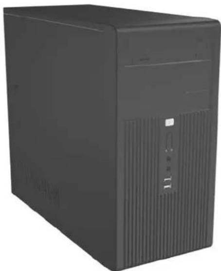
Figure 6-1 dx2300
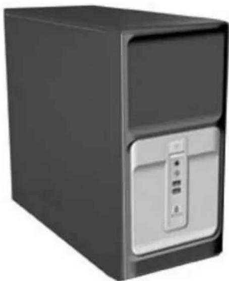
Figure 6-2 dx2308
Electrostatic Discharge Information
A sudden discharge of static electricity from your finger or other conductor can destroy static-sensitive devices or microcircuitry. Often the spark is neither felt nor heard, but damage occurs. An electronic device exposed to electrostatic discharge (ESD) may not appear to be affected at all and can work perfectly throughout a normal cycle. The device may function normally for a while, but it has been degraded in the internal layers, reducing its life expectancy.
Networks built into many integrated circuits provide some protection, but in many cases, the discharge contains enough power to alter device parameters or melt silicon junctions.
Generating Static
The following table shows that:
• Different activities generate different amounts of static electricity. • Static electricity increases as humidity decreases.
| Relative Humidity | |||
| Event | 55% 40% 10% | ||
| Walking across carpet | 7,500 V | 15,000 V | 35,000 V |
| Walking across vinyl floor | 3,000 V | 5,000 V | 12,000 V |
| Motions of bench worker | 400 V | 800 V | 6,000 V |
| Removing DIPs* from plastic tube | 400 V | 700 V | 2,000 V |
| Removing DIPs* from vinyl tray | 2,000 V | 4,000 V | 11,500 V |
| Removing DIPs* from Styrofoam | 3,500 V | 5,000 V | 14,500 V |
| Removing bubble pack from PCB | 7,000 V | 20,000 V | 26,500 V |
| Packing PCBs in foam-lined box | 5,000 V | 11,000 V | 21,000 V |
*These are then multi-packaged inside plastic tubes, trays, or Styrofoam.

NOTE: 700 volts can degrade a product.
Preventing Electrostatic Damage to Equipment
Many electronic components are sensitive to ESD. Circuitry design and structure determine the degree of sensitivity. The following packaging and grounding precautions are necessary to prevent damage to electric components and accessories.
• To avoid hand contact, transport products in static-safe containers such as tubes, bags, or boxes. - Protect all electrostatic parts and assemblies with conductive or approved containers or packaging. - Keep electrostatic sensitive parts in their containers until they arrive at static-free stations. - Place items on a grounded surface before removing them from their container. • Always be properly grounded when touching a sensitive component or assembly.
- Avoid contact with pins, leads, or circuitry.
- Place reusable electrostatic-sensitive parts from assemblies in protective packaging or conductive foam.
Personal Grounding Methods and Equipment
Use the following equipment to prevent static electricity damage to equipment:
- Wrist straps are flexible straps with a maximum of one-megohm ± 10% resistance in the ground cords. To provide proper ground, a strap must be worn snug against bare skin. The ground cord must be connected and fit snugly into the banana plug connector on the grounding mat or workstation.
- Heel straps/Toe straps/Boot straps can be used at standing workstations and are compatible with most types of shoes or boots. On conductive floors or dissipative floor mats, use them on both feet with a maximum of one-megohm ± 10% resistance between the operator and ground.
| Static Shielding Protection Levels | |
| Method | Voltage |
| Antistatic plastic | 1,500 |
| Carbon-loaded plastic | 7,500 |
| Metallized laminate | 15,000 |
Grounding the Work Area
To prevent static damage at the work area, use the following precautions:
- Cover the work surface with approved static-dissipative material. Provide a wrist strap connected to the work surface and properly grounded tools and equipment. • Use static-dissipative mats, foot straps, or air ionizers to give added protection.
- Handle electrostatic sensitive components, parts, and assemblies by the case or PCB laminate. Handle them only at static-free work areas. • Turn off power and input signals before inserting and removing connectors or test equipment. • Use fixtures made of static-safe materials when fixtures must directly contact dissipative surfaces.
- Keep work area free of nonconductive materials such as ordinary plastic assembly aids and Styrofoam. • Use field service tools, such as cutters, screwdrivers, and vacuums, that are conductive.
Recommended Materials and Equipment
Materials and equipment that are recommended for use in preventing static electricity include:
- Antistatic tape • Antistatic smocks, aprons, or sleeve protectors • Conductive bins and other assembly or soldering aids
- Conductive foam • Conductive tabletop workstations with ground cord of one-megohm +/- 10% resistance • Static-dissipative table or floor mats with hard tie to ground Field service kits • Static awareness labels • Wrist straps and footwear straps providing one-megohm +/- 10% resistance • Material handling packages • Conductive plastic bags • Conductive plastic tubes • Conductive tote boxes
- Opaque shielding bags • Transparent metallized shielding bags • Transparent shielding tubes
Operating Guidelines
To prevent overheating and to help prolong the life of the computer:
- Keep the computer away from excessive moisture, direct sunlight, and extremes of heat and cold.
- Operate the computer on a sturdy, level surface. Leave a 10.2-cm (4-inch) clearance on all vented sides of the computer and above the monitor to permit the required airflow.
- Never restrict the airflow into the computer by blocking any vents or air intakes. Do not place the keyboard, with the keyboard feet down, directly against the front of the desktop unit as this also restricts airflow.
- Occasionally clean the air vents on all vented sides of the computer. Lint, dust, and other foreign matter can block the vents and limit the airflow. Be sure to unplug the computer before cleaning the air vents.
- Never operate the computer with the cover or side panel removed.
- Do not stack computers on top of each other or place computers so near each other that they are subject to each other's re-circulated or preheated air.
- If the computer is to be operated within a separate enclosure, intake and exhaust ventilation must be provided on the enclosure, and the same operating guidelines listed above will still apply.
- Keep liquids away from the computer and keyboard.
- Never cover the ventilation slots on the monitor with any type of material. • Install or enable power management functions of the operating system or other software, including sleep states.
Routine Care
General Cleaning Safety Precautions
- Never use solvents or flammable solutions to clean the computer.
- Never immerse any parts in water or cleaning solutions; apply any liquids to a clean cloth and then use the cloth on the component.
- Always unplug the computer when cleaning with liquids or damp cloths.
- Always unplug the computer before cleaning the keyboard, mouse, or air vents.
- Disconnect the keyboard before cleaning it.
- Wear safety glasses equipped with side shields when cleaning the keyboard.
Cleaning the Computer Case
Follow all safety precautions in General Cleaning Safety Precautions on page 32 before cleaning the computer.
To clean the computer case, follow the procedures described below:
• To remove light stains or dirt, use plain water with a clean, lint-free cloth or swab. - For stronger stains, use a mild dishwashing liquid diluted with water. Rinse well by wiping it with a cloth or swab dampened with clear water. - For stubborn stains, use isopropyl (rubbing) alcohol. No rinsing is needed as the alcohol will evaporate quickly and not leave a residue. • After cleaning, always wipe the unit with a clean, lint-free cloth. - Occasionally clean the air vents on the computer. Lint and other foreign matter can block the vents and limit the airflow.
Cleaning the Keyboard
Follow all safety precautions in General Cleaning Safety Precautions on page 32 before cleaning the keyboard.
To clean the tops of the keys or the keyboard body, follow the procedures described in Cleaning the Computer Case on page 32.
When cleaning debris from under the keys, review all rules in General Cleaning Safety Precautions on page 32 before following these procedures:

CAUTION: Use safety glasses equipped with side shields before attempting to clean debris from under the keys.
- Visible debris underneath or between the keys may be removed by vacuuming or shaking.
- Canned, pressurized air may be used to clean debris from under the keys. Caution should be used as too much air pressure can dislodge lubricants applied under the wide keys.
- If you remove a key, use a specially designed key puller to prevent damage to the keys. This tool is available through many electronic supply outlets.

CAUTION: Never remove a wide leveled key (like the space bar) from the keyboard. If these keys are improperly removed or installed, the keyboard may not function properly.
Cleaning under a key may be done with a swab moistened with isopropyl alcohol and squeezed out. Be careful not to wipe away lubricants necessary for proper key functions. Use tweezers to remove any fibers or dirt in confined areas. Allow the parts to air dry before reassembly.
Cleaning the Monitor
- Wipe the monitor screen with a clean cloth moistened with water or with a towelette designed for cleaning monitors. Do not use sprays or aerosols directly on the screen; the liquid may seep into the housing and damage a component. Never use solvents or flammable liquids on the monitor. To clean the monitor body, follow the procedures in Cleaning the Computer Case on page 32.
Cleaning the Mouse
Before cleaning the mouse, ensure that the power to the computer is turned off.
- Clean the mouse ball by first removing the retaining plate and the ball from the housing. Pull out any debris from the ball socket and wipe the ball with a clean, dry cloth before reassembly. To clean the mouse body, follow the procedures in Cleaning the Computer Case on page 32.
Service Considerations
Listed below are some of the considerations that you should keep in mind during the disassembly and assembly of the computer.
Power Supply Fan
The power supply fan is a variable-speed fan based on the temperature in the power supply.

CAUTION: The cooling fan is always on when the computer is in the "On" mode. The cooling fan is off when the computer is in "Standby," "Suspend," or "Off" modes.
You must disconnect the power cord from the power source before opening the computer to prevent system board or component damage.
Tools and Software Requirements
To service the computer, you need the following:
• Torx T-15 screwdriver (HP screwdriver with bits, PN 161946-001) - Torx T-15 screwdriver with small diameter shank (for certain front bezel removal) - Flat-bladed screwdriver (may sometimes be used in place of the Torx screwdriver) • Phillips #2 screwdriver • Diagnostics software HP tamper-resistant T-15 wrench (Smart Cover FailSafe Key, PN 166527-001) or HP tamper-resistant bits (Smart Cover FailSafe Key, PN 166527-002)
Screws
The screws used in the computer are not interchangeable. They may have standard or metric threads and may be of different lengths. If an incorrect screw is used during the reassembly process, it can damage the unit. HP strongly recommends that all screws removed during disassembly be kept with the part that was removed, then returned to their proper locations.

CAUTION: Metric screws have a black finish. U.S. screws have a silver finish and are used on hard drives only.
CAUTION: As each subassembly is removed from the computer, it should be placed away from the work area to prevent damage.
Cables and Connectors
Most cables used throughout the unit are flat, flexible cables. These cables must be handled with care to avoid damage. Apply only the tension required to seat or unseat the cables during insertion or removal from the connector. Handle cables by the connector whenever possible. In all cases, avoid bending or twisting the cables, and ensure that the cables are routed in such a way that they cannot be caught or snagged by parts being removed or replaced.

CAUTION: When servicing this computer, ensure that cables are placed in their proper location during the reassembly process. Improper cable placement can damage the computer.
Hard Drives
Handle hard drives as delicate, precision components, avoiding all physical shock and vibration. This applies to failed drives as well as replacement spares.
- If a drive must be mailed, place the drive in a bubble-pack mailer or other suitable protective packaging and label the package "Fragile: Handle With Care."
- Do not remove hard drives from the shipping package for storage. Keep hard drives in their protective packaging until they are actually mounted in the CPU.
- Avoid dropping drives from any height onto any surface.
- If you are inserting or removing a hard drive, turn off the computer. Do not remove a hard drive while the computer is on or in standby mode.
- Before handling a drive, ensure that you are discharged of static electricity. While handling a drive, avoid touching the connector. For more information about preventing electrostatic damage, refer to Electrostatic Discharge Information on page 29. Do not use excessive force when inserting a drive.
- Avoid exposing a hard drive to liquids, temperature extremes, or products that have magnetic fields such as monitors or speakers.
Lithium Coin Cell Battery
The battery that comes with the computer provides power to the real-time clock and has a minimum lifetime of about three years.
See the appropriate removal and replacement chapter for the chassis you are working on in this guide for instructions on the replacement procedures.

WARNING! This computer contains a lithium battery. There is a risk of fire and chemical burn if the battery is handled improperly. Do not disassemble, crush, puncture, short external contacts, dispose in water or fire, or expose it to temperatures higher than 140°F (60°C). Do not attempt to recharge the battery.

NOTE: Batteries, battery packs, and accumulators should not be disposed of together with the general household waste. In order to forward them to recycling or proper disposal, please use the public collection system or return them to HP, their authorized partners, or their agents.
7 Removal and Replacement Procedures—Microtower (MT) Chassis
Adherence to the procedures and precautions described in this chapter is essential for proper service. After completing all necessary removal and replacement procedures, run the Diagnostics utility to verify that all components operate properly.

NOTE: Not all features listed in this guide are available on all computers.
Preparation for Disassembly
- Close any open software applications.
- Exit the operating system.
- Remove any diskette or compact disc from the computer.
- Turn off the computer and any peripheral devices that are connected to it.

CAUTION: Turn off the computer before disconnecting any cables.
CAUTION: Regardless of the power-on state, voltage is always present on the system board as long as the system is plugged into an active AC outlet. In some systems the cooling fan is on even when the computer is in the "Standby," or "Suspend" modes. The power cord should always be disconnected before servicing a unit.
- Disconnect the power cord from the electrical outlet and then from the computer.
- Disconnect all peripheral device cables from the computer.

NOTE: During disassembly, label each cable as you remove it, noting its position and routing. Keep all screws with the units removed.

CAUTION: The screws used in the computer are of different thread sizes and lengths; using the wrong screw in an application may damage the unit.
Access Panel
- Prepare the computer for disassembly (Preparation for Disassembly on page 37).

CAUTION: Before removing the computer access panel, ensure that the computer is turned off and that the power cord is disconnected from the electrical outlet.
- Disconnect the power cord from the computer and from the power source (1).
- Remove the two screws that secure the access panel to the computer chassis (2).
- Slide the access panel back about 6 mm (1/4 inch), then rotate the top of the panel away from the chassis (pivot on the bottom) and lift it off the unit (3).
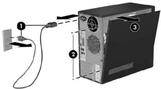
Figure 7-1 Removing the Access Panel
To replace the access panel, reverse the removal steps.
Front Bezel
- Prepare the computer for disassembly (Preparation for Disassembly on page 37)
- Remove the access panel (Access Panel on page 38)
- Press down on all three tabs (1) on the left side of the bezel then, rotate the bezel off the chassis (2), beginning with the left side and then the right side.
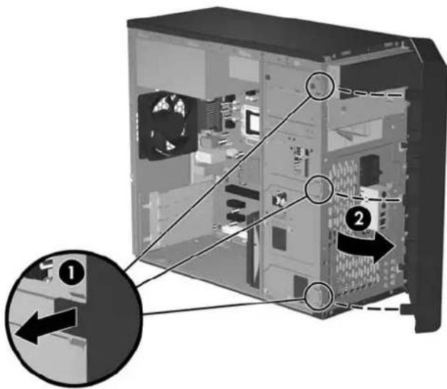
To reinstall the front bezel, reverse the removal procedure.
Front Drive Bezels
- Prepare the computer for disassembly (Preparation for Disassembly on page 37)
- Remove the access panel (Access Panel on page 38)
- Remove the front bezel (Front Bezel on page 39)
5.25" Drive Bezel Blank
While facing the inside of the front bezel, press the two retaining tabs on the right towards the outer edge of the bezel (1) and pull the bezel blank inwards (2) to remove it.
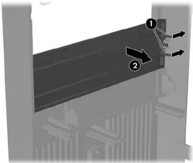
To install a bezel blank, reverse the removal procedure.
Removing a 3.5" Drive Bezel Blank
While facing the inside of the front bezel, press outward on the retaining tabs on each side of the bezel blank (1) and pull the bezel blank inwards to remove it.
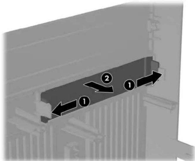

NOTE: To install a 3.5" bezel blank, press the blank inward from the inside of the front bezel so that it snaps into place.
Memory
The computer comes with double data rate 2 synchronous dynamic random access memory (DDR2-SDRAM) dual inline memory modules (DIMMs).

CAUTION: DDR and DDR2 memory modules are not interchangeable.
DDR2-SDRAM DIMMs
The memory sockets on the system board can be populated with up to two industry-standard DIMMs. These memory sockets are populated with at least one preinstalled DIMM. To achieve the maximum memory support, you can populate the system board with up to 2 GB (2 x 1GB) of memory configured in a high-performing dual channel mode.
For proper system operation, the DDR2-SDRAM DIMMs must be:
• industry-standard 240-pin • unbuffered PC2-5300 667 MHz-compliant 1.8 volt DDR2-SDRAM DIMMs
The DDR2-SDRAM DIMMs must also:
• support CAS latency 4 for PC2–5300 667 MHz • contain the mandatory JEDEC SPD information
In addition, the computer supports:
• 256Mbit, 512Mbit, and 1Gbit non-ECC memory technologies • single-sided and double-sided DIMMs DIMMs constructed with x8 and x16 DDR devices; DIMMs constructed with x4 SDRAM are not supported

NOTE: The system will not start if you install unsupported DIMMs.
Installing Memory Modules

CAUTION: The memory module sockets have gold metal contacts. When upgrading the memory, it is important to use memory modules with gold metal contacts to prevent corrosion and/or oxidation resulting from having incompatible metals in contact with each other.
CAUTION: Static electricity can damage the electronic components of the computer or optional cards. Before beginning these procedures, ensure that you are discharged of static electricity by briefly touching a grounded metal object.
CAUTION: When handling a memory module, be careful not to touch any of the contacts. Doing so may damage the module.
- Prepare the computer for disassembly (Preparation for Disassembly on page 37).
- Remove the access panel and lay the computer down on its side to make it easier to work on. (Panel on page 38)
Access

WARNING! To reduce risk of personal injury from hot surfaces, allow the internal system components to cool before touching.
- Open both latches of the memory module socket (1), and insert the memory module into the socket (2). Begin by installing a module into the socket nearest the pre-installed module, and install the modules following the numerical order of the sockets.
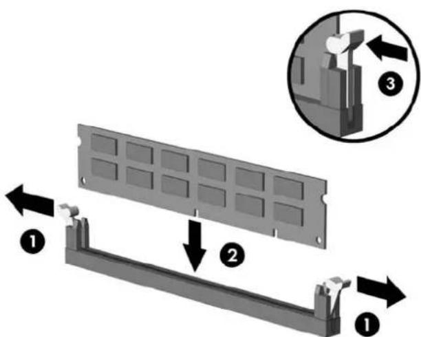

NOTE: A memory module can be installed in only one way. Match the notch on the module with the tab on the memory socket.
- Push the module down into the socket, ensuring that the module is fully inserted and properly seated. Make sure the latches are in the closed position (3).
- Repeat steps 4 and 5 for any additional modules that you want to install.
To reassemble the computer, reverse the removal procedure.
Expansion Cards
Expansion Slot Cover Lock
- Prepare the computer for disassembly (Preparation for Disassembly on page 37)
- Remove the access panel (Access Panel on page 38)
- Lay the computer down on its side to make it easier to work on.
- On the rear of the computer, remove the screw that secures the slot cover lock in place (1), then slide the slot cover lock up and away from the slots to remove it from the computer (2).
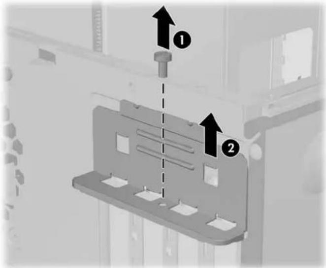
To reinstall the slot cover lock, reverse the removal procedure.
PCI/PCIe Expansion Card
To remove an expansion card, continue with step 1.
To install an expansion card in an existing empty slot, go to step 9.
- Prepare the computer for disassembly (Preparation for Disassembly on page 37).
- Remove the access panel (Access Panel on page 38).
- Lay the computer down on its side to make it easier to work on.
- Remove the slot cover lock (Expansion Slot Cover Lock on page 44).
If you are installing an expansion card for the first time, go to step 9.
If you are replacing an existing expansion card, go to step 5.
- Disconnect any cables attached to the expansion card.
- Hold the card at each end and carefully rock it back and forth until the connectors pull free from the socket. Be sure not to scrape the card against other components.
- Store the card in anti-static packaging.
- Install a new expansion card or an expansion slot cover to close the open slot.
To install a replacement expansion card, go to step 10.
- If you are installing an expansion card for the first time, you must first remove the expansion slot cover. Use a flat blade screwdriver to pry out the metal shield on the rear panel that covers the expansion slot. Be sure you remove the appropriate shield for the expansion card you are installing.
Removable Shield Expansion Card Type
Top shield PCI Express x16
Second shield PCI Express x1
Third shield PCI Express x1
Bottom shield PCI
- With the card aligned so the mounting bracket will fit firmly against the computer backwall, slide the expansion card into the expansion socket and press it firmly into place.
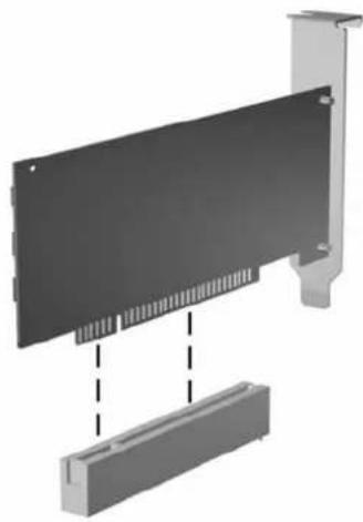

NOTE: When you install an expansion card, make sure you press firmly on the card so that the entire connector seats properly in the expansion card socket.
- Reinstall the slot cover lock and its retaining screw.
- Replace the access panel.
- Connect external cables to the installed card, if needed.
Reconfigure the computer, if necessary.
Cable Management
Always follow good cable management practices when working inside the computer.
- Keep cables away from major heat sources like the heatsink.
- Do not jam cables on top of expansion cards or memory modules. Printed circuit cards like these are not designed to take excessive pressure on them.
- When folding a flat ribbon cable, never fold to a sharp crease. Sharp creases may damage the wires. • Some flat ribbon cables come prefolded. Never change the folds on these cables. • Do not bend any cable sharply. A sharp bend can break the internal wires.
- Never bend a SATA data cable tighter than a 30 mm (1.18 in) radius. • Never crease a SATA data cable.
- Do not rely on components like the drive cage, power supply, or computer cover to push cables down into the chassis. Always position the cables to lay properly by themselves.
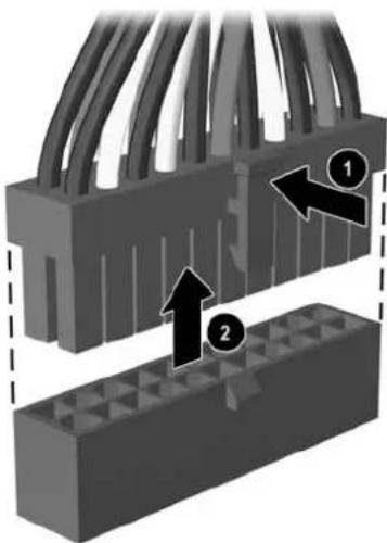
When removing the power supply power cable from the P1 connector on the system board, always follow these steps:
- Squeeze on the top of the retaining latch attached to the cable end of the connector (1).
- Grasp the cable end of the connector and pull it straight up (2).

CAUTION: Always pull the connector - NEVER pull on the cable. Pulling on the cable could damage the cable and result in a failed power supply.
Cable Connections
Cable To Cable Designator
| Power Supply System board, 24-pin P1 |
| Power Supply CPU power, 4-pin P2 |
| Power Supply Not used P3 |
| Power Supply Not used P4 |
| Power Supply 2nd SATA Hard drive P5 |
| Power Supply 1st SATA Hard drive P6 |
| Power Supply Diskette drive P7 |
| Power Supply 2nd Optical drive P8 |
| Power Supply 1st Optical drive P9 |
Cable To PCA Designator
| Diskette drive System board FDD1 |
| 1st SATA Hard drive System board SATA1 |
| 2nd SATA Hard drive System board SATA2 |
Primary ODD System board SATA3
| Second ODD | System board SATA4 | |
| Heatsink fan | System board CPU_FAN1 | |
| Chassis fan | System board SYS_FAN1 | |
| Front power on button | System board | JFP1 |
| Front I/O USB | System board JUSB1 | |
| Speaker | System board SPKR | |
| Front audio | System board AUD1 | |
| Second Serial Port | System board | JCOM1 |
| Media Card Reader | System board JUSB2 |
Drives
The computer supports up to five drives that may be installed in various configurations.
This section describes the procedure for replacing or upgrading the storage drives. A Torx T-15 screwdriver is needed to remove and install the guide screws on a drive.

CAUTION: Make sure personal files on the hard drive are backed up to an external storage device before removing the hard drive. Failure to do so will result in data loss. After replacing the primary hard drive, you will need to run the Restore Plus! CD to load the Compaq factory-installed files.
Drive Positions
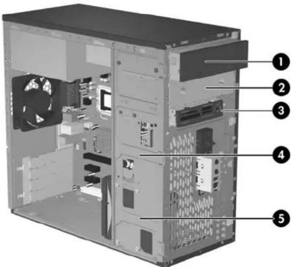
Drive Positions
| Item | Description Item Description | |
| (1) | Optical drive* | (4) Internal hard drive (secondary) |
| (2) | Optical drive* | (5) Internal hard drive (primary) |
| (3) | External 3.5" drive# | |
An optical drive is a CD-ROM, CD-R/RW, DVD-ROM, DVD-R/RW, or CD-RW/DVD Combo drive. Optical media card reader illustrated.
5.25" Drive
- Prepare the computer for disassembly (Preparation for Disassembly on page 37)
- Remove the access panel (Access Panel on page 38)
- Remove the front bezel (Front Bezel on page 39)
- Disconnect the power, data, and audio cables, as necessary, from the back of the drive.
- Remove the two screws that secure the drive in the drive cage (1).
- Slide the drive out of the drive cage, as shown in the illustration below (2).
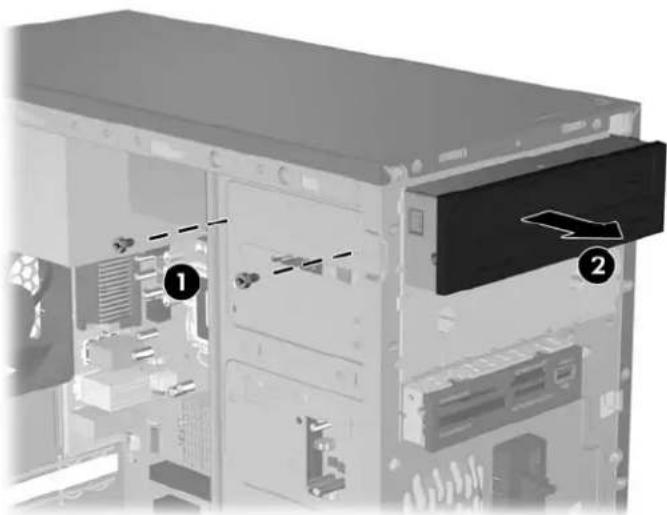
- After the drive has been removed from the chassis, remove the two guide screws from the left side of the drive. These screws should be transferred to the new drive.
To install a drive, reverse the removal procedure.

NOTE: If you are installing a 5.25" drive for the first time into bay 2, you must first remove the metal shield that covers the bay by pressing in on the silver-colored tab on the left side of the chassis, then pulling the shield out from the front of the chassis. It is not necessary to remove the drive from bay 1 when performing this operation.
NOTE: There are a total of eight extra guide/retainer screws on the front of the chassis behind the bezel. Four have Unified Standard (US) #6-32 standard threads and four have M3 metric threads. US screws are used for hard drives and have a silver finish. Metric screws are used for all other drives and have a black finish. Be sure to install the appropriate guide screws into the drive.
3.5" Drive
If you are installing a device for the first time in the external 3.5" drive bay, you will need to use a flat blade screwdriver to break out the metal shield.
The 3.5" external drive bay may be populated with a diskette drive or a media card reader. The removal procedure is the same for both devices.
- Prepare the computer for disassembly (Preparation for Disassembly on page 37).
- Remove the access panel (Access Panel on page 38).
- Remove the front bezel (Front Bezel on page 39).
- If the device is a media card reader, disconnect the internal USB cable from the system board. If the device is a diskette drive, disconnect the power and data cables from the back of the drive.
- Remove the retainer screws that secure the drive in the bay (1), then slide the drive forward and out of the bay (2).
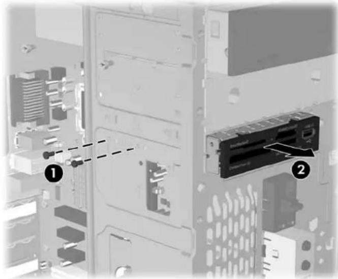
To install a drive, reverse the removal procedure. Be sure to install a guide screw on the front right side of a new drive. The guide screw helps secure the drive in place.
Refer to the table below for proper retainer and guide screw locations.
| Device Retainer Screws Guide Screws | ||
| Diskette Drive | 2 (labeled “FDD” on chassis) | 1 (front left side of drive) |
| Media Card Reader 2 (labeled “CR” on chassis) none | ||

NOTE: If you are installing a drive in the external 3.5" drive bay for the first time, use a flat blade screwdriver to pry out the metal shield covering the bay.
NOTE: There are a total of eight extra guide/retainer screws on the front of the chassis behind the bezel. Four have Unified Standard (US) #6-32 standard threads and four have M3 metric threads. US screws are used for hard drives and have a silver finish. Metric screws are used for all other drives and have a black finish. Be sure to install the appropriate guide screws into the drive.
Removing a 3.5" Hard Drive
- Prepare the computer for disassembly (Preparation for Disassembly on page 37)
- Remove the access panel (Access Panel on page 38)
- Remove the front bezel (Front Bezel on page 39)
- Disconnect the power and data cables from the back of the drive.
- Remove the four retaining screws that secure the drive in the drive cage (1).
- Slide the drive out of the rear of the drive bay (2).
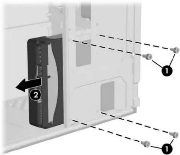
To replace the hard drive cage, reverse the removal procedure. No guide screws are required for drives installed in the hard drive bays (bays 4 and 5).

NOTE: If you replaced the primary hard drive, the Restore Plus! CD may be used to restore the operating system, software drivers, and/or any software applications that were preinstalled on the computer. Follow the instructions in the guide included with the CD. When the restore process has been completed, reinstall any personal files that were backed up before replacing the hard drive.
Front I/O Panel Housing Assembly
- Prepare the computer for disassembly (Preparation for Disassembly on page 37)
- Remove the access panel and rotate the computer so the system board is parallel to the table to make it easier to work on (Access Panel on page 38)
- Remove the front bezel (Front Bezel on page 39)
- Free the two cables from the cable tie that is attached to the chassis.
- Remove the screw (1) that secures the housing to the chassis and then rotate the housing away from the chassis and pull the assembly out of the chassis.
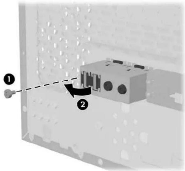
To install the housing assembly, reverse the removal procedures.
Power Switch Assembly
- Prepare the computer for disassembly (Preparation for Disassembly on page 37).
- Remove the access panel and rotate the computer so the system board is parallel to the table to make it easier to work on (Access Panel on page 38).
- Disconnect the braided cables from the system board.
- Free the braided cables from the cable tie that is attached to the chassis.
- Squeeze the top of the switch holder (1), rotate the switch, and remove it from the chassis.
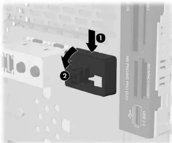
To install the power switch assembly, reverse the removal procedures.
Speaker
- Prepare the computer for disassembly (Preparation for Disassembly on page 37).
- Remove the access panel (Access Panel on page 38).
- Remove the front bezel (Front Bezel on page 39).
- Disconnect the speaker cable from the system board.
- Free the cable from the cable tie that is attached to the chassis.
- Remove the screw that secures the speaker to the inside of the chassis (1), then remove the speaker (2) by sliding it out of the retaining clips.
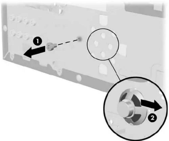
To install the speaker, reverse the removal procedure.
When installing the speaker, make sure the speaker wires point towards the speaker retaining screw.
Second Serial Port
- Prepare the computer for disassembly (Preparation for Disassembly on page 37).
- Remove the access panel (Access Panel on page 38).
- Disconnect the serial port cable from the system board.
- Disconnect the serial port cable from the two clips (1) mounted on the inside of the chassis.
- Remove the two retaining screws from the outside of the chassis that secure the serial port to the chassis (2), and remove the serial port.
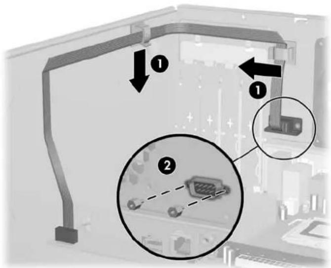
System Fan
- Prepare the computer for disassembly (Preparation for Disassembly on page 37)
- Remove the access panel (Access Panel on page 38)
- Disconnect the cable that connects the system fan to the system board.
- Cut the tie-wrap (1) at the bottom of the fan that secures the CPU power cable (2) to the fan.
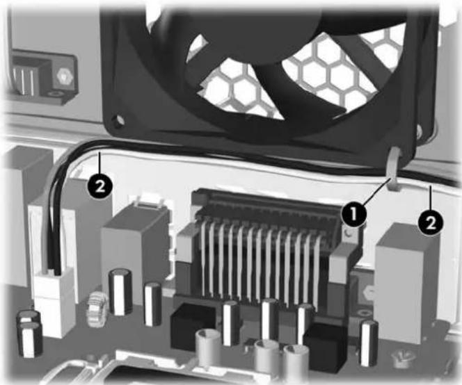
- Remove the screws that secure the fan to the chassis and remove the fan.
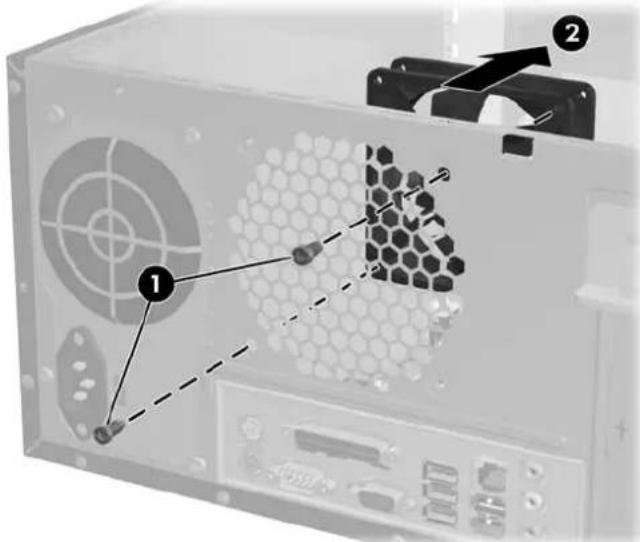
To install the fan, reverse the removal procedures.

NOTE: When installing the fan, the CPU power cable must be plugged into the system board before securing the cable to the bottom of the fan cage. This will ensure that the cable is properly positioned.
Heatsink
- Prepare the computer for disassembly (Preparation for Disassembly on page 37)
- Remove the access panel and lay the computer down on its side to make it easier to work on. (Panel on page 38)
Access
- Disconnect the heatsink control cable from the system board.
- Loosen the four captive screws that secure the heatsink to the system board.
- Lift the heatsink from atop the processor and set it on its side to keep from contaminating the work area with thermal grease.
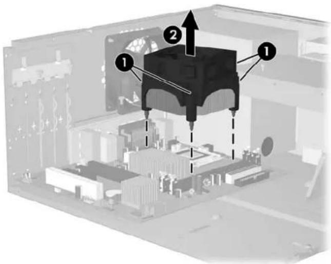
When reinstalling an existing heatsink, make sure that its bottom has been cleaned with an alcohol wipe and fresh thermal grease has been applied to the top of the processor. New heatsinks come from the factory with fresh thermal grease already applied.
Position the heatsink so that fan wiring is closest to the power supply. Check to ensure that the heatsink mounting lugs do not rest on any electrical components before tightening the retaining screws.

CAUTION: Heatsink retaining screws should be tightened in diagonally opposite pairs (as in an X) to evenly seat the heatsink to the processor. This is especially important as the pins on the socket are very fragile and any damage to them may require replacing the system board.
Processor
- Prepare the computer for disassembly (Preparation for Disassembly on page 37).
- Remove the access panel and lay the computer down on its side to make it easier to work on. (Access Panel on page 38).
- Disconnect the heatsink control cable from the system board and remove the heatsink. Heatsink on page 59
- Rotate the locking lever to its full open position (1).
- Raise and rotate the microprocessor retainer to its full open position (2).
- Carefully lift the processor from the socket (3).

CAUTION: Do NOT handle the pins in the processor socket. These pins are very fragile and handling them could cause irreparable damage. Once pins are damaged it may be necessary to replace the system board.
CAUTION: The heatsink must be installed within 24 hours of installing the processor to prevent damage to the processor's solder connections.
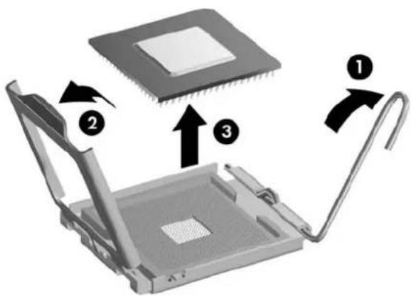
To install a new processor:
- Place the processor in its socket and close the retainer.
- Secure the locking lever.
If reusing the existing heatsink, go to step 3.
If using a new heatsink, go to step 6.
- If reusing the existing heatsink, clean the bottom of the heatsink with the alcohol pad provided in the spares kit.
- Apply the thermal grease provided in the spares kit to the top of the processor and install the heatsink atop the processor.
- Go to step 7.
- If using a new heatsink, remove the protective covering from the bottom of the heatsink and place it in position atop the processor.
- Secure the heatsink to the system board and system board tray with the 4 captive screws and attach the heatsink control cable to the system board.

CAUTION: Heatsink retaining screws should be tightened in diagonally opposite pairs (as in an X) to evenly seat the heatsink on the processor. This is especially important as the pins on the socket are very fragile and any damage to them may require replacing the system board.

NOTE: After installing a new processor onto the system board, always update the system ROM to ensure that the latest version of the BIOS is being used on the computer. The latest system ROM BIOS can be found on the Web at: http://h18000.www1.hp.com/support/files.
System Board
- Prepare the computer for disassembly (Preparation for Disassembly on page 37)
- Remove the access panel. (Access Panel on page 38)
- Remove the front bezel and lay the computer down on its side to make it easier to work on. (Front Bezel on page 39).
- Disconnect the power and data cables from the back of all installed drives.
- Disconnect all cables from the system board.
- Remove the heatsink from the system board (Heatsink on page 59)
- Remove the 6 screws that secure the system board to the chassis (1).
- Slide the system board towards the front of the chassis (2) then remove it from the chassis.

NOTE: The system board in the computer may look slightly different from the one shown here.
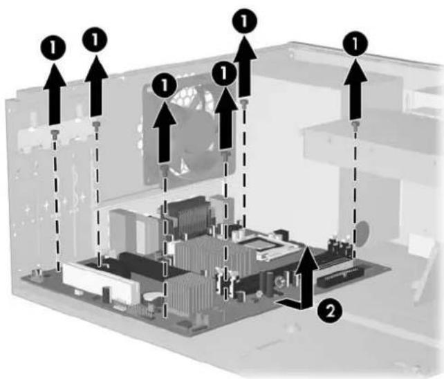
To install the system board, reverse the removal procedure.

NOTE: After installing a new system board, always update the system ROM to ensure that the latest version of the BIOS is being used on the computer. The latest system ROM BIOS can be found on the Web at: http://h18000.www1.hp.com/support/files.
Battery
The battery that comes with your computer provides power to the real-time clock and has a lifetime of about three years. When replacing the battery, use a battery equivalent to the battery originally installed on the computer. The computer comes with a 3-volt lithium coin cell battery.

NOTE: The lifetime of the lithium battery can be extended by plugging the computer into a live AC wall socket. The lithium battery is only used when the computer is NOT connected to AC power.

WARNING! This computer contains an internal lithium manganese dioxide battery. There is a risk of fire and burns if the battery is not handled properly. To reduce the risk of personal injury:
Do not attempt to recharge the battery.
Do not expose to temperatures higher than 60°C (140°F).
Do not disassemble, crush, puncture, short external contacts, or dispose of in fire or water.
Replace the battery only with the HP/Compaq spare designated for this product.

CAUTION: Before replacing the battery, it is important to back up the computer CMOS settings. When the battery is removed or replaced, the CMOS settings will be cleared. Refer to the Troubleshooting Guide for information on backing up the CMOS settings.

NOTE: Batteries, battery packs, and accumulators should not be disposed of together with the general household waste. In order to forward them to recycling or proper disposal, please use the public collection system or return them to HP/Compaq, their authorized partners, or their agents.

CAUTION: Static electricity can damage the electronic components of the computer or optional equipment. Before beginning these procedures, ensure that you are discharged of static electricity by briefly touching a grounded metal object.
- Prepare the computer for disassembly (Preparation for Disassembly on page 37)
- Remove the access panel (Access Panel on page 38).

NOTE: It may be necessary to remove an expansion card to gain access to the battery.
- Locate the battery and battery holder on the system board.
Type 1 Battery Holder
- Lift the battery out of its holder.
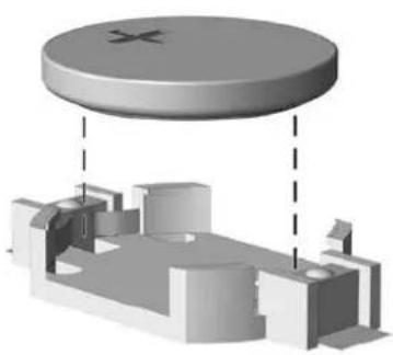
- Slide the replacement battery into position, positive side up.
- The battery holder automatically secures the battery in the proper position.
- Replace the computer access panel.
- Plug in the computer and turn on power to the computer.
- Reset the date and time, your passwords, and any special system setups, using Computer Setup. Refer to the Computer Setup (F10) Utility Guide.
Type 2 Battery Holder
- To release the battery from its holder, squeeze the metal clamp that extends above one edge of the battery. When the battery pops up, lift it out (1).
- To insert the new battery, slide one edge of the replacement battery under the holder's lip with the positive side up (2). Push the other edge down until the clamp snaps over the other edge of the battery.
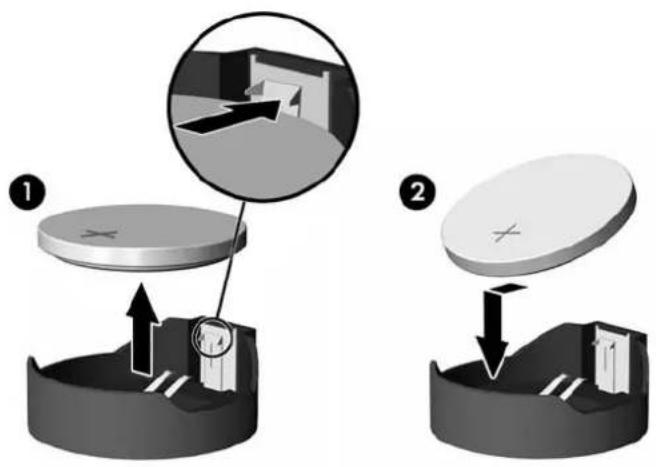
- Replace the computer access panel.
- Plug in the computer and turn on power to the computer.
- Reset the date and time, your passwords, and any special system setups, using Computer Setup. Refer to the Computer Setup (F10) Utility Guide.
Type 3 Battery Holder
- Pull back on the clip (1) that holds the battery in place, then remove the battery (2).
- Insert the new battery and position the clip back in place.
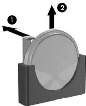
- Replace the computer access panel.
- Plug in the computer and turn on power to the computer.
- Reset the date and time, your passwords, and any special system setups, using Computer Setup. Refer to the Computer Setup (F10) Utility Guide.
Power Supply

WARNING! Voltage is always present on the system board when the computer is plugged into an active AC outlet. To avoid possible personal injury and damage to the equipment, the power cord should be disconnected from the computer and/or the AC outlet before opening the computer.
- Prepare the computer for disassembly (Preparation for Disassembly on page 37).
- Remove the access panel (Access Panel on page 38).
- Disconnect all power cables from the mass storage devices and from the system board.
- Cut the tie wrap (1) at the bottom of the fan that secures the CPU power cable (2) to the fan cage.
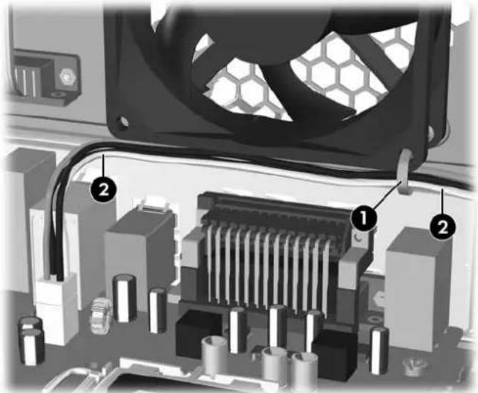
- Remove the 4 screws (1) that secure the power supply to the chassis.
- Slide the power supply toward the front of the computer, then lift it out of the computer.
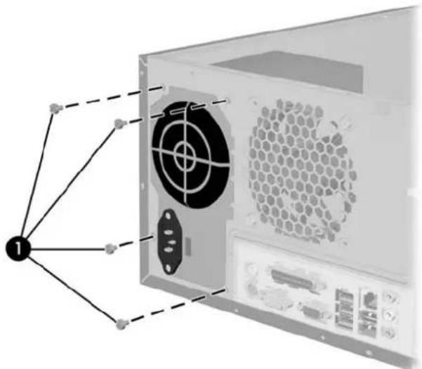
To install the power supply, reverse the removal procedure.

NOTE: When attaching the CPU power cable to the system board, use the tie-wrap provided in the spares kit to secure the cable to the lower right corner of the fan cage. This will prevent the wire bundle from interfering with the chassis fan blades.
A Connector Pin Assignments
This appendix contains the pin assignments for many computer and workstation connectors. Some of these connectors may not be used on the product being serviced.
Keyboard
| Connector and Icon Pin Signal | |||
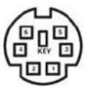 |  | 1 | Data |
| 2 | Unused | ||
| 3 | Ground | ||
| 4 | +5 VDC | ||
| 5 | Clock | ||
| 6 | Unused | ||
Mouse
| Connector and Icon Pin Signal | |||
| 1 | Data | ||
| 2 | Unused | ||
| 3 | Ground | ||
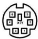 |  | 4 | +5 VDC |
| 5 | Clock | ||
| 6 | Unused | ||
Ethernet BNC
| Connector and Icon Pin Signal | |||
| 1 | Data | ||
 |  | 2 | Ground |
Ethernet RJ-45
| Connector and Icon Pin Signal | |||
| 1 | (+) Transmit Data | ||
| 2 | (-) Transmit Data | ||
| 3 | (+) Receive Data | ||
| 4 | Unused | ||
 |  | 5 | Unused |
| 6 | (-) Receive Data | ||
| 7 | Unused | ||
| 8 | Unused | ||
Ethernet AUI
| Connector and Icon | |||
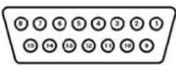 |  | ||
| Pin Signal | Pin Signal | ||
| 1 | Ground | 9 | Positive AUI Differential Receive |
| 2 | Negative AUI Differential Collision | 10 | +12V |
| 3 | Positive AUI Differential Collision | 11 | Ground |
| 4 | Negative AUI Differential Transmit | 12 | Ground |
| 5 | Positive AUI Differential Transmit | 13 | Unused |
| 6 | Ground | 14 | Unused |
| 7 | Ground | 15 | Unused |
| 8 | Negative AUI Differential Receive | 16 | Unused |
Parallel Interface
Connector and Icon B
| Pin Signal | Pin Signal | ||
| 1 | Strobe | 10 | Acknowledge |
| 2 | Data Bit 0 | 11 | Busy |
| 3 | Data Bit 1 | 12 | Paper End |
| 4 | Data Bit 2 | 13 | Select |
| 5 | Data Bit 3 | 14 | Auto Linefeed |
| 6 | Data Bit 4 | 15 | Error |
| 7 | Data Bit 5 | 16 | Initialize Printer |
| 8 | Data Bit 6 | 17 | Select IN |
| 9 Data Bit 7 18- | 25 | Signal Ground | |
Serial Interface, Powered and Non-Powered
Connector and Icon Pin Signal
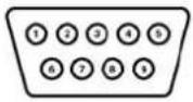 |  | 1 | Carrier Detect (12V if powered) |
| 2 | Receive Data | ||
| 3 | Transmit Data | ||
| 4 | Data Terminal Ready | ||
| 5 | Signal Ground | ||
| 6 | Data Set Ready | ||
| 7 | Request to Send | ||
| 8 | Clear to Send | ||
| 9 | Ring Indicator (5V if powered) |
USB
Connector and Icon Pin Signal
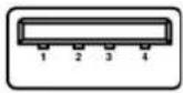 |  | 1 | +5 VDC |
| 2 | - Data | ||
| 3 | + Data | ||
| 4 | Ground |
Diskette Drive Power
| Connector and Icon Pin Signal | |||
| 1 | +5 VDC | ||
| 4 | 1 | 2 | Ground |
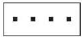 | 3 | Ground | |
| 4 | Reserved (+12 Volts) | ||
Microphone
| Connector and Icon (1/8" miniphone) Pin Signal | ||
| 1 (Tip) | Audio_left | |
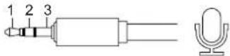 | 2 (Ring) | Audio_Right |
| 3 (Shield) | Ground | |
Headphone
| Connector and Icon (1/8" miniphone) Pin Signal | ||
| 1 (Tip) | Audio_left | |
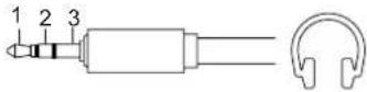 | 2 (Ring) | Power_Right |
| 3 (Shield) | Ground | |
Line-in Audio
| Connector and Icon (1/8" miniphone) Pin Signal | ||
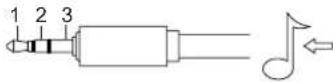 | 1 (Tip) | Audio_In_Left |
| 2 (Ring) | Audio_In_Right | |
| 3 (Shield) | Ground | |
Line-out Audio
| Connector and Icon (1/8" miniphone) Pin Signal | ||
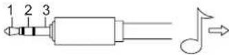 | 1 (Tip) | Audio_Out_Left |
| 2 (Ring) | Audio_Out_Right | |
| 3 (Shield) | Ground | |
External Infrared Transceiver
Connector and Icon Pin Signal
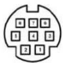 |  | 1 | Transmit |
| 2 | Receive | ||
| 3 | Ground | ||
| 4 | 5V | ||
| 5 | Mode | ||
| 6 | Not Used | ||
| 7 | Not Used | ||
| 8 | Not Used |
Monitor
Connector and Icon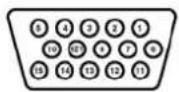
| Pin Signal | Pin Signal | ||
| 1 | Red Analog | 9 | +5V (fused) |
| 2 | Green Analog | 10 | Ground |
| 3 | Blue Analog | 11 | Not used |
| 4 | Not used | 12 | DDC Serial Data |
| 5 | Ground | 13 | Horizontal Sync |
| 6 | Ground | 14 | Vertical Sync |
| 7 | Ground | 15 | DDC Serial Clock |
| 8 | Ground | ||
Diskette Drive Standard Data Cable
Connector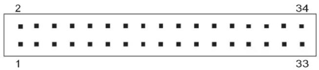
Pin Signal Pin Signal Pin Signal
| 1 | Ground | 13 | Ground | 25 | Ground |
| 2 | Low density | 14 | Reserved | 26 | Track 00 |
| 3 | Key | 15 | Ground | 27 | Ground |
| 4 | Media — ID | 16 | Motor On | 28 | Write Protect |
| 5 | Ground | 17 | Ground | 29 | Ground |
| 6 | No Signal | 18 | Direction In | 30 | Read Data |
| 7 | Ground | 19 | Ground | 31 | Ground |
| 8 | Index | 20 | Step | 32 | Side 1 Select |
| 9 | Ground | 21 | Ground | 33 | Ground |
| 10 | Reserved | 22 | Write data | 34 | Disk Change |
| 11 | Ground | 23 | Ground | ||
| 12 | Drive Select | 24 | Write Gate |
24-Pin Power
Connector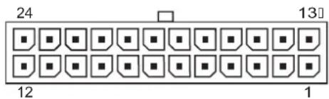
| Pin | Signal | Pin | Signal | Pin | Signal | Pin | Signal |
| 1 | +3.3V | 7 | GND | 13 | +3.3V | 19 | GND |
| 2 | +3.3V | 8 | POK | 14 | -12V | 20 | open |
| 3 | GND | 9 | +5 Vaux | 15 | GND | 21 | +5V |
| 4 | +5V | 10 | +12V | 16 | PSON | 22 | +5V |
| 5 | GND | 11 | +12V | 17 | GND | 23 | +5V |
| 6 | +5V | 12 | +3.3V | 18 | GND | 24 | GND |
24-Pin MicroFit Power
Connector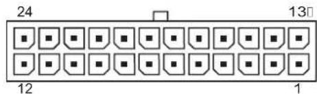
Pin Signal Pin Signal Pin Signal Pin Signal
| 1 | +5 Vaux | 7 | PWRGD | 13 | +12V | 19 | GND |
| 2 | GND | 8 | +3.3V | 14 | +5V Sense | 20 | +3.3V |
| 3 | +5V | 9 | +3.3V | 15 | GND | 21 | Sense |
| 4 | +5V | 10 | Tach | 16 | +5V | 22 | +3.3V |
| 5 | PS_ON | 11 | GND | 17 | +5V | 23 | +3.3V |
| 6 | GND | 12 | Fan-CMD | 18 | +3.3V | 24 | GND |
| -12V |
4-Pin Power (for CPU)
Connector and Icon Pin Signal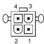
1 GND
2 GND
3 +12V CPU
4 -12V CPU
6-Pin Power (for CPU)
Connector and Icon Pin Signal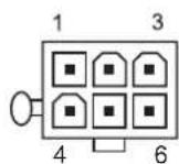
1 GND
2 GND
3 GND
4 12V CPU
5 12V CPU
6 +12V
SATA Data and Power
Drive Connector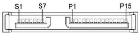
| Pin | Signal | Pin | Signal | Pin | Signal | Pin | Signal |
| S1 | Ground | S2 | A+ | S3 | A- | S4 | Ground |
| S5 | B- | S6 | B+ | S7 | Ground | ||
| P1 | Ground | P2 | V 3.3 | P3 | V 3.3 | P4 | Ground |
| P5 | B- | P6 | Ground | P7 | V 5 | P8 | V 5 |
| P9 | V 5 | P10 | Ground | P11 | Reserved | P12 | Ground |
| P13 | V 12 | P14 | V12 | P15 | V 12 |
* S = Data, P = Power
PCI Express
x1, x4, x8, and x16 PCI Express Connector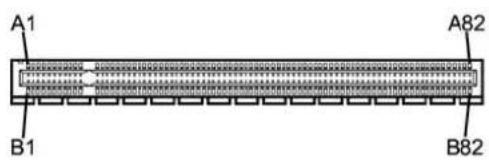
Pin A
| Pin | Signal | Pin | Signal | Pin | Signal | Pin | Signal | Pin | Signal |
| 1 | PRSNT1 | 6 | JTAG3 | 11 | PERST# | 16 | PERp0 | 21 | PERp1 |
| 2 | +12V | 7 | JTAG4 | 12 | GND | 17 | PERn0 | 22 | PERn1 |
| 3 | +12V | 8 | JTAG5 | 13 | REFCLK+ | 18 | GND | 23 | GND |
| 4 | GND | 9 | +3.3V | 14 | REFCLK- | 19 | RSVD | 24 | GND |
| 5 | JTAG2 | 10 | +3.3V | 15 | GND | 20 | GND | 25 | PERp2 |
| 26 | PERn(2) | 31 | GND | 36 | PERn4 | 41 | GND | 46 | GND |
| 27 | GND | 32 | RSVD | 37 | GND | 42 | GND | 47 | PERp7 |
| 28 | GND | 33 | RSVD | 38 | GND | 43 | PERp6 | 48 | PERn7 |
| 29 | PERp3 | 34 | GND | 39 | PERp5 | 44 | PERn6 | 49 | GND |
| 30 | PERn3 | 35 | PERp4 | 40 | PERn5 | 45 | GND | 50 | RSVD |
51 GND 56 PERp9 61 PERn10 66 GND 71 GND
| 52 | PERp8 | 57 | PERn9 | 62 | GND | 67 | GND | 72 | PERp13 |
| 53 | PERN8 | 58 | GND | 63 | GND | 68 | PERp12 | 73 | PERn13 |
| 54 | GND | 59 | GND | 64 | PERp11 | 69 | PERn12 | 74 | GND |
| 55 | GND | 60 | PERp10 | 65 | PERn11 | 70 | GND | 75 | GND |
| 76 | PERp14 | 81 | PERn15 | ||||||
| 77 | PERn14 | 82 | GND | ||||||
| 78 | GND | ||||||||
| 79 | GND | ||||||||
| 80 | PERp15 |
Pin B information is on the next page

NOTE: x1 PCI Express uses pins 1-18
x4 PCI Express uses pins 1-32
x8 PCI Express uses pins 1-49
x16 PCI Express uses pins 1-8
PCI Express
x1, x4, x8, and x16 PCI Express Connector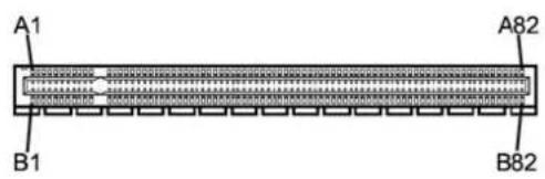
Pin B
| Pin | Signal | Pin | Signal | Pin | Signal | Pin | Signal | Pin | Signal |
| 1 | +12V | 6 | SMDAT | 11 | WAKE# | 16 | GND | 21 | GND |
| 2 | +12V | 7 | GND | 12 | RSVD | 17 | GND | 22 | GND |
| 3 | RSVD | 8 | +3.3 V | 13 | GND | 18 | PETp1 | 23 | PETp2 |
| 4 | GND | 9 | JTAG1 | 14 | PETp0 | 19 | PETn1 | 24 | PETn2 |
| 5 | SMCLK | 10 | 3.3vAux | 15 | PETn0 | 20 | 25 | GND | |
| 26 | GND | 31 | PRSNT2# | 36 | GND | 41 | PETp6 | 46 | PETn7 |
| 27 | PETp3 | 32 | GND | 37 | PETp5 | 42 | PRTn6 | 47 | GND |
| 28 | PETn3 | 33 | PETp4 | 38 | PETn5 | 43 | GND | 48 | PRSNT2# |
| 29 | GND | 34 | PETn4 | 39 | GND | 44 | GND | 49 | GND |
| 30 | RSVD | 35 | GND | 40 | GND | 45 | PETp7 | 50 | PETp8 |
| 51 | PETn8 | 56 | GND | 61 | GND | 66 | PETp12 | 71 | PETn13 |
| 52 | GND | 57 | GND | 62 | PETp11 | 67 | PETn12 | 72 | GND |
| 53 | GND | 58 | PETp10 | 63 | PETn11 | 68 | GND | 73 | GND |
| 54 | PETp9 | 59 | PETn10 | 64 | GND | 69 | GND | 74 | PETp14 |
| 55 | PETn9 | 60 | GND | 65 | GND | 70 | PETp13 | 75 | PETn14 |
| 76 | GND | 81 | PRSNT2# | ||||||
| 77 | GND | 82 | RSVD | ||||||
| 78 | PETp15 | ||||||||
| 79 | PETn15 | ||||||||
| 80 | GND |
Pin B information is on the next page

NOTE: x1 PCI Express uses pins 1-18
x4 PCI Express uses pins 1-32
x8 PCI Express uses pins 1-49
x16 PCI Express uses pins 1-8
DVI Connector
Connector and Icon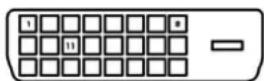
| Pin Signal | Pin Signal | ||
| 1 | T.M.D.S. Data2- | 13 | T.M.D.S. Data3+ |
| 2 | T.M.D.S. Data2+ | 14 | +5V Power |
| 3 | T.M.D.S. Data2/4 Shield | 15 | Ground (for +5V) |
| 4 | T.M.D.S. Data4- | 16 | Hot Pug Detect |
| 5 | T.M.D.S. Data4+ | 17 | T.M.D.S. Data0- |
| 6 | DDC Clock | 18 | T.M.D.S. Data0+ |
| 7 | DDC Data | 19 | T.M.D.S. Data0/5 Shield |
| 8 | No Connect | 20 | T.M.D.S. Data5- |
| 9 | T.M.D.S. Data1- | 21 | T.M.D.S. Data5+ |
| 10 | T.M.D.S. Data1+ | 22 | T.M.D.S. Data Shield |
| 11 | T.M.D.S. Data1/3 Shield | 23 | T.M.D.S. Clock+ |
12 T.M.D.S. Data3- 24 T.M.D.S. Clock-
B Power Cord Set Requirements
The power supplies on some computers have external power switches. The voltage select switch feature on the computer permits it to operate from any line voltage between 100-120 or 220-240 volts AC. Power supplies on those computers that do not have external power switches are equipped with internal switches that sense the incoming voltage and automatically switch to the proper voltage.
The power cord set received with the computer meets the requirements for use in the country where you purchased the equipment.
Power cord sets for use in other countries must meet the requirements of the country where you use the computer.
General Requirements
The requirements listed below are applicable to all countries:
- The power cord must be approved by an acceptable accredited agency responsible for evaluation in the country where the power cord set will be installed.
- The power cord set must have a minimum current capacity of 10A (7A Japan only) and a nominal voltage rating of 125 or 250 volts AC, as required by each country's power system.
- The diameter of the wire must be a minimum of 0.75 mm² or 18AWG, and the length of the cord must be between 1.8 m (6 feet) and 3.6 m (12 feet).
The power cord should be routed so that it is not likely to be walked on or pinched by items placed upon it or against it. Particular attention should be paid to the plug, electrical outlet, and the point where the cord exits from the product.

WARNING! Do not operate this product with a damaged power cord set. If the power cord set is damaged in any manner, replace it immediately.
Japanese Power Cord Requirements
For use in Japan, use only the power cord received with this product.

CAUTION: Do not use the power cord received with this product on any other products.
Country-Specific Requirements
Additional requirements specific to a country are shown in parentheses and explained below.
| Country Accrediting Agency | Country Accrediting Agency | ||
| Australia (1) | EANSW | Italy (1) | IMQ |
| Austria (1) | OVE | Japan (3) | METI |
| Belgium (1) | CEBC | Norway (1) | NEMKO |
| Canada (2) | CSA | Sweden (1) | SEMKO |
| Denmark (1) | DEMKO | Switzerland (1) | SEV |
| Finland (1) | SETI | United Kingdom (1) | BSI |
| France (1) | UTE | United States (2) | UL |
| Germany (1) | VDE | ||
- The flexible cord must be Type HO5VV-F, 3-conductor, 0.75 mm² conductor size. Power cord set fittings (appliance coupler and wall plug) must bear the certification mark of the agency responsible for evaluation in the country where it will be used.
- The flexible cord must be Type SVT or equivalent, No. 18 AWG, 3-conductor. The wall plug must be a two-pole grounding type with a NEMA 5-15P (15A, 125V) or NEMA 6-15P (15A, 250V) configuration.
- Appliance coupler, flexible cord, and wall plug must bear a "T" mark and registration number in accordance with the Japanese Dentori Law. Flexible cord must be Type VCT or VCTF, 3-conductor, 0.75 mm² conductor size. Wall plug must be a two-pole grounding type with a Japanese Industrial Standard C8303 (7A, 125V) configuration.
C Troubleshooting
Safety and Comfort

WARNING! Misuse of the computer or failure to establish a safe and comfortable work environment may result in discomfort or serious injury. Refer to the Safety & Comfort Guide on the Documentation and Diagnostics CD and available on the Web site at http://www.hp.com/ergo for more information on choosing a workspace and creating a safe and comfortable work environment.
Helpful Hints
If you encounter problems with the computer, monitor, or software, see the following list of general suggestions before taking further action:
- Check that the computer and monitor are plugged into a working electrical outlet.
- Check to see that the voltage select switch (some models) is set to the appropriate voltage for your region (115V or 230V).
- Check to see that the computer is turned on and the green power light is on.
- Check to see that the monitor is turned on and the green monitor light is on.
- Turn up the brightness and contrast controls of the monitor if the monitor is dim.
- Press and hold any key. If the system beeps, then the keyboard should be operating correctly.
- Check all cable connections for loose connections or incorrect connections.
- Wake the computer by pressing any key on the keyboard or pressing the power button. If the system remains in suspend mode for more than four seconds, shut down the computer by pressing and holding the power button for at least four seconds then press the power button again to restart the computer. If the system will not shut down, unplug the power cord, wait a few seconds, then plug it in again. The computer will restart if automatic start on power loss is set in Computer Setup. If it does not restart, press the power button to start the computer.
- Reconfigure your computer after installing a non-plug and play expansion board or other option.
- Be sure that all the needed device drivers have been installed. For example, if you are using a printer, you need a driver for that model printer.
- Remove all bootable media (diskette, CD, or USB device) from the system before turning it on.
- If you have installed an operating system other than the factory-installed operating system, check to be sure that it is supported on the system.
- If the system has multiple video sources (embedded, PCI, or PCI-Express adapters) installed and a single monitor, the monitor must be plugged into the monitor connector on the source selected as the primary VGA adapter. During boot, the other monitor connectors are disabled and if the monitor is connected into these ports, the monitor will not function. You can select which source will be the default VGA source in Computer Setup.

CAUTION: When the computer is plugged into an AC power source, there is always voltage applied to the system board. You must disconnect the power cord from the power source before opening the computer to prevent system board or component damage.
Solving General Problems
You may be able to easily resolve the minor problems described in this section.
Computer will not turn on.
| Cause Solution | |
| Cables to the external power source are unplugged. | Ensure that cables connecting the computer to the external power source are plugged in properly and the wall outlet is active. |
| Voltage selector switch on rear of computer chassis (some models) not switched to correct line voltage (115V or 230V). | Select the proper AC voltage using the selector switch. |
| A defective PCI card has been installed. | Remove any expansion board that was just installed. |
| Drive data or power supply cables may not be properly connected. | Reseat drive data and power supply cables. |
| The unit temperature was exceeded. The fan may be blocked. | Unit is in an exceedingly hot environment. Let it cool down.Ensure that computer air vents are not blocked and the internal fan is running. |
Computer appears locked up and will not turn off when the power button is pressed.
| Cause | Solution |
| Software control of the power switch is not functional. | 1. Press and hold the power button for at least four seconds until the computer turns off.2. Disconnect the power cord from the electrical outlet. |
Computer will not respond to USB keyboard or mouse.
| Cause Solution | |
| System has locked up. Restart computer. | |
| Keyboard or mouse is not connected to computer. | Connect keyboard and mouse cables to computer. |
| Computer is instandbymode. | To resume fromstandbymode, press the power button or press any key. |
| CAUTION:When attempting to resume fromstandbymode, do not hold down the power button for more than four seconds. Otherwise, the computer will shut down and you will lose any unsaved data. | |
Computer date and time display is incorrect.
| Cause | Solution |
| RTC (real-time clock) battery may need to be replaced. | First, reset the date and time under Control Panel (Computer Setup can also be used to update the RTC date and time). If the problem persists, replace the RTC battery. |
Computer date and time display is incorrect.
Cause Solution

NOTE: Connecting the computer to a live AC outlet prolongs the life of the RTC battery.
Cursor will not move using the arrow keys on the keypad.
| Cause | Solution |
| The Num Lock key may be on. | Press the Num Lock key. The Num Lock light should not be on if you want to use the arrow keys. The Num Lock key can be disabled (or enabled) in Computer Setup. |
Poor performance is experienced.
| Cause Solution | |
| Processor is hot. | 1. Make sure airflow to the computer is not blocked. Leave a 10.2-cm (4-inch) clearance on all vented sides of the computer and above the monitor to permit the required airflow.2. Make sure fans are connected and working properly (some fans only operate when needed).3. Make sure the processor heatsink is installed properly. |
| Hard drive is full. Transfer data from the hard drive to create more space on the hard drive. | |
| Low on memory. Add more memory. | |
| Hard drive fragmented. Defragment hard drive. | |
| Program previously accessed did not release reserved memory back to the system. | Restart the computer. |
| Virus resident on the hard drive. Run virus protection program. | |
| Too many applications running. | 1. Close unnecessary applications to free up memory. Some applications run in the background and can be closed by right-clicking on their corresponding icons in the task tray. To prevent these applications from launching at startup, go to Start > Run (Microsoft Windows XP) or Start > All Programs > Accessories > Run (Microsoft Windows Vista) and type msconfig. On the Startup tab of the System Configuration Utility, uncheck applications that you do not want to launch automatically. CAUTION: Do not prevent applications from launching at startup that are required for proper system operation.2. Add more memory. CAUTION: Do not prevent applications from launching at startup that are required for proper system operation.2. Add more memory. |
Poor performance is experienced.
| Cause Solution | |
| Some software applications, especially games, are stressful on the graphics subsystem | 1. Lower the display resolution for the current application or consult the documentation that came with the application for suggestions on how to improve performance by adjusting parameters in the application.2. Add more memory.3. Upgrade the graphics solution. |
| Cause unknown. Restart the computer. | |
Blank screen (no video).
| Cause Solution | |
| Monitor is not turned on and the monitor light is not on. | Turn on the monitor and check that the monitor light is on. |
| The cable connections are not correct. Check the cable connection from the monitor to the computer and to the electrical outlet. | |
| You may have a screen blanking utility installed or energy saver features are enabled. | Press any key or click the mouse button and, if set, type your password. |
| Computer is instandbymode. | Press the power button to resume fromstandbymode. |
| CAUTION:When attempting to resume fromstandbymode, do not hold down the power button for more than four seconds. Otherwise, the computer will shut down and you will lose any unsaved data. | |
| You are using a fixed-sync monitor and it will not sync at the resolution chosen. | Be sure that the monitor can accept the same horizontal scan rate as the resolution chosen. |
| Monitor cable is plugged into the wrong connector. | Ensure that the monitor is plugged into an active connector on the rear of the computer. If another connector is available, connect the monitor to that connector and reboot the system. |
| Bad monitor. Try a different monitor. | |
Power LED is flashing and computer will not start.
| Cause | Solution |
| Internal error has occurred and the computer is flashing a code. | Refer to Interpreting Diagnostic Lights on page 89 to interpret the error code. |
Solving Hardware Installation Problems
You may need to reconfigure the computer when you add or remove hardware, such as an additional drive or expansion card. If you install a plug and play device, the Windows operating system automatically recognizes the device and configures the computer. If you install a non-plug and play device, you must reconfigure the computer after completing installation of the new hardware. In the Windows operating system, use the Add Hardware Wizard and follow the instructions that appear on the screen.

WARNING! When the computer is plugged into an AC power source, voltage is always applied to the system board. To reduce the risk of personal injury from electrical shock, rotating fans, and/or hot surfaces, be sure to disconnect the power cord from the wall outlet and allow the internal system components to cool before touching.
Look for the LED on the system board. If the LED is illuminated, the system still has power. Power off the computer and remove the power cord before proceeding.
A new device is not recognized as part of the system.
| Cause | Solution |
| Device is not seated or connected properly. | Ensure that the device is properly and securely connected and that pins in the connector are not bent down. |
| Cable(s) of new external device are loose or power cables are unplugged. | Ensure that all cables are properly and securely connected and that pins in the cable or connector are not bent down. |
| Power switch of new external device is not turned on. | Turn off the computer, turn on the external device, then turn on the computer to integrate the device with the computer system. |
| When the system advised you of changes to the configuration, you did not accept them. | Reboot the computer and follow the instructions for accepting the changes. |
| A plug and play board may not automatically configure when added if the default configuration conflicts with other devices. | Use Windows Device Manager to deselect the automatic settings for the board and choose a basic configuration that does not cause a resource conflict. You can also use Computer Setup to reconfigure or disable devices to resolve the resource conflict. |
| USB ports on the computer are disabled in Computer Setup. | Enter Computer Setup (F10) and enable the USB ports. |
Computer will not start.
Cause Solution
| Wrong memory modules were used in the upgrade or memory modules were installed in the wrong location. | 1. Review the documentation that came with the system to determine if you are using the correct memory modules and to verify the proper installation.2. Observe the LED lights on the front of the computer. See Interpreting Diagnostic Lights on page 89 to determine possible causes.3. If you still cannot resolve the issue, contact Customer Support. |
Interpreting Diagnostic Lights
This section covers the front panel LED codes that may occur before or during POST that do not necessarily have an error code or text message associated with them.

NOTE: If you see flashing LEDs on a PS/2 keyboard, look for flashing LEDs on the front panel of the computer and refer to the following table to determine the front panel LED codes.
Recommended actions in the following table are listed in the order in which they should be performed.
Replace the system board or power supply only as the last resort.
| Activity Possible Cause Recommended Action | ||
| Green Power LED On. Computer on. None | ||
| Green Power LED flashes every one second. | Processor thermal protection activated:A fan may be blocked or not turning.ORThe heatsink/fan assembly is not properly attached to the processor. | 1.Ensure that the computer air vents are not blocked and the processor cooling fan is running.2.Open hood, press power button, and see if the processor fan spins. If the processor fan is not spinning, make sure the fan's cable is plugged onto the system board header. Ensure the fan is fully/properly seated or installed.WARNING! Rotating fan blades can cause serious bodily harm. Be sure to keep your hands away from the rotating blades.3.If fan is plugged in and seated properly, but is not spinning, then replace processor fan.4.Reseat processor heatsink and verify that the fan assembly is properly attached.5.Contact an authorized reseller or service provider. |
| Green Power LED flashes every two seconds. | Computer in Suspend to RAM mode (some models only) or normal Suspend mode. | Press any key or move the mouse to wake the computer. |
| Green Power LED flashes four times per second. | Pre-video memory error. | CAUTION:To avoid damage to the DIMMs or the system board, you must unplug the computer power cord before attempting to reseat, install, or remove a DIMM module.1.Reseat DIMMs.2.Replace DIMMs one at a time to isolate the faulty module.3.Replace third-party memory with HP memory.4.Replace the system board. |
Activity Possible Cause Recommended Action
| Green Power LED flashes six times, once every second, followed by a two second pause. | Pre-video graphics error. For systems with a graphics card: | |
| 1. Reseat the graphics card. | ||
| 2. Replace the graphics card. | ||
| 3. Replace the system board. | ||
| For systems with integrated graphics, replace the system board. | ||
| Green Power LED flashes eight times, once every second, followed by a two second pause. | Invalid ROM based on bad checksum. | 1. Reflash the system ROM with the latest BIOS image. |
| 2. Replace the system board. | ||
| System does not power on and LEDs are not flashing. | System unable to power on. Press and hold the power button for less than 4 seconds. If the hard drive LED turns green, the power button is working correctly. Try the following: | |
| 1. Check that the voltage selector (some models), located on the rear of the power supply, is set to the appropriate voltage. Proper voltage setting depends on your region. | ||
| 2. Replace the system board. | ||
| OR | ||
| Press and hold the power button for less than 4 seconds. If the hard drive LED does not turn on green then: | ||
| 1. Check that the unit is plugged into a working AC outlet. | ||
| 2. Open hood and check that the power button harness is properly connected to the system board. | ||
| 3. Check that both power supply cables are properly connected to the system board. | ||
| 4. Check to see if the 5V_aux light on the system board is turned on. If it is turned on, then replace the power button harness. If the problem persists, replace the system board. | ||
| 5. If the 5V_aux light on the system board is not turned on, remove the expansion cards one at a time until the 5V_aux light on the system board turns on. It the problem persists, replace the power supply. | ||
Index
Symbols/Numerics
24-pin MicroFit power pin assignments 75
24-pin power pin assignments 74
4-pin power pin assignments 75
5.25" drive bezel blank 40
6-pin power pin assignments 75
A
access panel, removal and replacement 38
adding devices 1
B
Backup and Recovery Manager 2
battery disposal 35, removal and replacement 63
bezel blank, 5.25" drive 40
BIOS Boot Block Emergency Recovery Mode 21
Boot Block Emergency Recovery Mode 21
C
cable connections 48
cable lock provision 23
cable management 47
cable pinouts SATA data 25
cautions
AC power 27
adding devices 1
cables 35
cooling fan 34
electrostatic discharge 29
keyboard cleaning 33
keyboard keys 33
operating system installation 1 protecting ROM 21
changing operating systems, important information 22
chassis types, illustrated 27
chassis MT illustrated 27
cleaning
computer 32
mouse 34
safety precautions 32
computer cleaning 32
connector pin assignments 69
country power cord set requirements 81
D
device drivers, installing 1
diagnostic tool for hard drives 23
diagnostics utility 13
disassembly preparation 37
diskette drive cable pin assignments 74
diskette drive power pin assignments 72
drive
5.25" removal and replacement 50
hard drive removal and replacement 51
drive positions 49
drive, protecting 23
DriveLock applications 23 using 22
DVI pin assignments 78
E
electrostatic discharge (ESD) preventing damage 29
Emergency Recovery Mode, Boot Block 21
ethernet AUI pin assignments 70 BNC pin assignments 69 RJ-45 pin assignments 70
expansion card removal and replacement 45
expansion slot cover lock removal and replacement 44
F
fan, power supply 34
Fault Notification and Recovery HP Client Manager 23
front bezel removal and replacement 39
front drive bezel 40
front I/O panel removal and replacement 54
G
grounding methods 30
H
hard drive proper handling 35 removal and replacement 51, 53
SATA characteristics 25
hard drives, diagnostic tool 23
headphone pin assignments 72
heatsink removal and replacement 59
HP Backup and Recovery Manager 2
HP Insight Diagnostics 13
I
infrared (IR) transceiver, external, pin assignments 73
Insight Diagnostics 13
internal temperature of computer 24
Internet addresses. See Web sites
K
keyboard
cleaning 33
pin assignments 69
L
line-in audio pin assignments 72
line-out audio pin assignments 72
M
memory
specifications 42
memory, removal and replacement 42
microphone pin assignments 72
monitor
pin assignments 73
mouse
pin assignments 69
mouse cleaning 34
MT
chassis, illustrated 27
0
operating guidelines 32
operating systems, important information about 22
overheating, prevention 32
P
parallel interface pin assignments 71
PCI Express pin assignments 76
power cord set requirements country specific 81
power supply fan 34
removal and replacement 67
power supply, surge-tolerant 24
power switch assembly, removal and replacement 55
Preboot Execution Environment (PXE) 20
preparation for disassembly 37
processor removal and replacement 60
protecting hard drive 23
protecting ROM, caution 21
PXE (Preboot Execution Environment) 20
R
recovery
creating disc recovery set 2
Recovery Mode, Boot Block Emergency 21
remote setup 20
Remote System Installation 20
removal and replacement 5.25" drive 50
access panel 38
battery 63
expansion card 45
expansion slot cover lock 44
front bezel 39
front I/O panel 54
hard drive 51, 53
heatsink 59
memory 42
power switch assembly 55
processor 60
speaker 56
system board 62
system fan 58
removal and replacement, serial port 57
Restore Plus! CD 2
ROM
flash 21
S
safety precautions cleaning 32
SATA
connectors on system board 25
data cable pinouts 25
hard drive characteristics 25
pin assignments 76
screws, correct size 34
SDRAM (synchronous dynamic random access memory) 42
security
cable lock 23
DriveLock 22
serial interface pin assignments 71
serial port, removal and replacement 57
service considerations 34
software
Drive Protection System 23
HP Backup and Recovery Manager 2
HP Insight Diagnostics 13
Remote System Installation 20
Restore Plus! CD 2
servicing computer 34
spare part number
tamper-resistant wrench 34
Torx T-15 screwdriver 34
speaker, removal and replacement 56
Specifications
Memory 42
Static electricity 29
Surge-tolerant power supply 24
System board
SATA connectors 25
System board removal and replacement 62
System fan, removal and replacement 58
T
Tamper-proof screws tool 34
Temperature control 32
Temperature, internal computer 24
Thermal sensor 24
Tools, servicing 34
Torx T15 screwdriver 34
URLs (Web sites). See Web sites
USB pin assignments 71
ventilation, proper 32
Web sites
BIOS download 21
ROM Flash 21
software support 22


- SERVICE REFERENCE GUIDE
- ABOUT THIS BOOK
- TABLE OF CONTENTS
- INSTALL THE OPERATING SYSTEM
- COMPUTER SETUP (F10) UTILITY
- HP INSIGHT DIAGNOSTICS
- DESKTOP MANAGEMENT
- SERIAL ATA (SATA) DRIVE GUIDELINES AND FEATURES
- IDENTIFYING THE CHASSIS, ROUTINE CARE, AND DISASSEMBLY PREPARATION
- REMOVAL AND REPLACEMENT PROCEDURES—MICROTOWER (MT) CHASSIS
- APPENDIX A CONNECTOR PIN ASSIGNMENTS
- APPENDIX B POWER CORD SET REQUIREMENTS
- APPENDIX C TROUBLESHOOTING
- INSTALLING OR UPGRADING DEVICE DRIVERS
- HP BACKUP AND RECOVERY MANAGER
- COMPUTER SETUP (F10) UTILITIES
- USING COMPUTER SETUP (F10) UTILITIES
- TO APPLY AND SAVE CHANGES, PRESS THE F10 KEY
- COMPUTER SETUP—SYSTEM INFORMATION
- COMPUTER SETUP—ADVANCED
- COMPUTER SETUP—PC HEALTH
- COMPUTER SETUP—ACTIONS
- RECOVERING THE CONFIGURATION SETTINGS
- BACKING UP THE CMOS
- RESTORING THE CMOS
- ACCESSING HP INSIGHT DIAGNOSTICS
- SURVEY TAB
- TEST TAB
- STATUS TAB
- LOG TAB
- HELP TAB
- SAVING AND PRINTING INFORMATION IN HP INSIGHT DIAGNOSTICS
- DOWNLOADING THE LATEST VERSION OF HP INSIGHT DIAGNOSTICS
- REMOTE SYSTEM INSTALLATION
- ROM FLASH
- BOOT BLOCK EMERGENCY RECOVERY MODE
- HP WEB SITE SUPPORT
- SECURITY
- DRIVELOCK
- USING DRIVELOCK
- DRIVELOCK APPLICATIONS
- CABLE LOCK PROVISION
- FAULT NOTIFICATION AND RECOVERY
- DRIVE PROTECTION SYSTEM
- SURGE-TOLERANT POWER SUPPLY
- THERMAL SENSOR
- SATA HARD DRIVE CABLES
- SATA DATA CABLE
- SMART ATA DRIVES
- HARD DRIVE CAPACITIES
- CHASSIS DESIGNATIONS
- MICROTOWER (MT)
- ELECTROSTATIC DISCHARGE INFORMATION
- GENERATING STATIC
- PREVENTING ELECTROSTATIC DAMAGE TO EQUIPMENT
- PERSONAL GROUNDING METHODS AND EQUIPMENT
- GROUNDING THE WORK AREA
- RECOMMENDED MATERIALS AND EQUIPMENT
- OPERATING GUIDELINES
- ROUTINE CARE
- GENERAL CLEANING SAFETY PRECAUTIONS
- CLEANING THE COMPUTER CASE
- CLEANING THE KEYBOARD
- CLEANING THE MONITOR
- CLEANING THE MOUSE
- SERVICE CONSIDERATIONS
- POWER SUPPLY FAN
- TOOLS AND SOFTWARE REQUIREMENTS
- SCREWS
- CABLES AND CONNECTORS
- HARD DRIVES
- LITHIUM COIN CELL BATTERY
- PREPARATION FOR DISASSEMBLY
- ACCESS PANEL
- FRONT BEZEL
- FRONT DRIVE BEZELS
- DRIVE BEZEL BLANK
- REMOVING A 3.5" DRIVE BEZEL BLANK
- MEMORY
- DDR2-SDRAM DIMMS
- INSTALLING MEMORY MODULES
- EXPANSION CARDS
- EXPANSION SLOT COVER LOCK
- PCI/PCIE EXPANSION CARD
- CABLE MANAGEMENT
- CABLE CONNECTIONS
- DRIVES
- DRIVE POSITIONS
- DRIVE
- REMOVING A 3.5" HARD DRIVE
- FRONT I/O PANEL HOUSING ASSEMBLY
- POWER SWITCH ASSEMBLY
- SPEAKER
- SECOND SERIAL PORT
- SYSTEM FAN
- HEATSINK
- PROCESSOR
- SYSTEM BOARD
- BATTERY
- TYPE 1 BATTERY HOLDER
- TYPE 2 BATTERY HOLDER
- TYPE 3 BATTERY HOLDER
- POWER SUPPLY
- A CONNECTOR PIN ASSIGNMENTS
- ETHERNET RJ
- ETHERNET AUI
- PARALLEL INTERFACE
- SERIAL INTERFACE, POWERED AND NON-POWERED
- USB
- DISKETTE DRIVE POWER
- MICROPHONE
- HEADPHONE
- LINE-IN AUDIO
- LINE-OUT AUDIO
- EXTERNAL INFRARED TRANSCEIVER
- MONITOR
- DISKETTE DRIVE STANDARD DATA CABLE
- PIN POWER
- PIN MICROFIT POWER
- PIN POWER (FOR CPU)
- SATA DATA AND POWER
- PCI EXPRESS
- DVI CONNECTOR
- B POWER CORD SET REQUIREMENTS
- GENERAL REQUIREMENTS
- JAPANESE POWER CORD REQUIREMENTS
- COUNTRY-SPECIFIC REQUIREMENTS
- C TROUBLESHOOTING
- SAFETY AND COMFORT
- HELPFUL HINTS
- SOLVING GENERAL PROBLEMS
- CAUSE SOLUTION
- SOLVING HARDWARE INSTALLATION PROBLEMS
- COMPUTER WILL NOT START
- INTERPRETING DIAGNOSTIC LIGHTS
- INDEX
- SYMBOLS/NUMERICS
- A
- B
- C
- D
- E
- F
- G
- H
- I
- K
- L
- M
- P
- R
- S
- T
Brand : HP
Model : Compaq dx2308
Category : Unclassified