
ECOCOND - Water heaters Elco - Free user manual and instructions
Find the device manual for free ECOCOND Elco in PDF.


| Product Type | Gas Condensing Water Heater with Storage Tank |
| Brand | Elco |
| Model | ECOCOND |
| Dimensions (H x W x D) | 800 x 600 x 600 mm |
| Weight | 45 kg |
| Energy Supply | Natural Gas or Propane (2000-2400 Pa) |
| Tank Capacity | 100 L |
| Power Input | 24 kW |
| Efficiency | Up to 98% (Condensing) |
| Temperature Range | 30 - 65 °C |
| Energy Class | A |
| Noise Level | < 50 dB(A) |
| Flow Rate (ΔT=35°C) | 9.8 L/min |
| Main Functions | Condensing technology, electronic ignition, automatic temperature control, frost protection, anti-legionella cycle |
| Maintenance & Cleaning | Annual service recommended; clean burner, heat exchanger, and check sacrificial anode |
| Safety Features | Safety valve, overheat protection, flame failure device, gas leak detection |
| Spare Parts & Repairability | Available: burner, heat exchanger, control board, fan, expansion vessel |
| Installation | Wall-mounted, indoor use, flue gas evacuation to chimney or outside |
| Manufacturing | Made in Europe |
Frequently Asked Questions - ECOCOND Elco
User questions about ECOCOND Elco
0 question about this device. Answer the ones you know or ask your own.
Ask a new question about this device
Download the instructions for your Water heaters in PDF format for free! Find your manual ECOCOND - Elco and take your electronic device back in hand. On this page are published all the documents necessary for the use of your device. ECOCOND by Elco.
USER MANUAL ECOCOND Elco
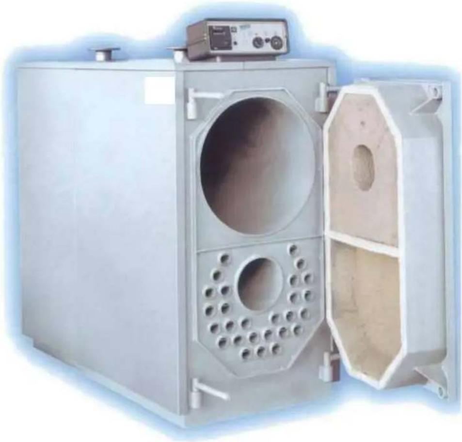
Forced Draught Three Pass Stainless Steel Condensing Boiler
Installation and User Guide
natural_image
Exterior view of a large industrial oven with circular vent and side compartments (no visible text or symbols)CONTENTS
General description...... page 3
Technical data...... page 3
Connections...... page 4
Clearances ...... page 5
Dimensions ...... page 5
Handling ...... page 6
Location...... page 6
Combustion chamber door opening and adjustment ...... page 6
Burner mounting...... page 7
Minimum return temperature - Oil firing ...... page 7
Fuel supply ...... page 8
Mounting the control panel ...... page 8
Flue system ...... page 8
Flue gas condensation neutralising device (Optional extra)...... page 9
System water ...... page 9
Control panel schematic...... page 10
Preliminary Checks...... page 11
First start up...... page 11
User instructions...... page 12
Operation / Controls...... page 14
General Description
The Ecocond series of boilers are forced draught combustion type, stainless steel condensing appliances. Suitable for use with appropriate power flame burners with Natural Gas, LPG, Light or Heavy Fuel Oil or Biodiesel.
11 models in the range with outputs from 117.6kW to 707.7kW Working pressure 5bar
CE0085
natural_image
Exterior view of a white industrial machine with circular vent and side panel (no visible text or symbols)Technical Data
| Model Ecocond | 110 | 150 | 190 | 230 | 290 | 345 | 405 | 440 | 520 | 580 | 640 |
| Output 80/60°C kW | 110 | 148 | 185 | 227 | 286 | 345 | 400 | 436.7 | 518.9 | 570.4 | 641.3 |
| Output 40/30°C kW | 117.6 | 160.3 | 200.4 | 244.8 | 309.7 | 372.3 | 438.9 | 482.1 | 572.8 | 629.1 | 707.7 |
| Input (net) kW | 113.3 | 152 | 189.6 | 232.3 | 292 | 351.7 | 407.3 | 458.7 | 545 | 599 | 673.6 |
| Combustion chamber resistance mbar | 1.0 | 1.2 | 1.6 | 2.0 | 2.3 | 3.3 | 3.9 | 3.5 | 4.2 | 5.5 | 6.6 |
| Hydraulic resistance Δt 10K kPa | 1.53 | 2.25 | 3.6 | 2.25 | 3.15 | 5.17 | 6.74 | 4.03 | 4.94 | 6.05 | 7.86 |
| Hydraulic resistance Δt 15K kPa | 0.68 | 1.0 | 1.6 | 1.0 | 1.4 | 2.3 | 3.0 | 1.8 | 2.2 | 2.7 | 3.5 |
| Hydraulic resistance Δt 20K kPa | 0.39 | 0.56 | 0.9 | 0.56 | 0.78 | 1.3 | 1.68 | 1.00 | 1.23 | 1.51 | 1.96 |
| Nominal design flow rate Δt 10K l/s | 2.61 | 3.52 | 4.4 | 5.4 | 6.8 | 8.21 | 9.52 | 10.39 | 12.35 | 13.58 | 15.26 |
| Nominal design flow rate Δt 15K l/s | 1.74 | 2.34 | 2.93 | 3.60 | 4.53 | 5.47 | 6.34 | 6.93 | 8.23 | 9.05 | 10.17 |
| Nominal design flow rate Δt 20K l/s | 1.3 | 1.76 | 2.2 | 2.7 | 3.4 | 4.1 | 4.76 | 5.19 | 6.17 | 6.79 | 7.63 |
| Max working pressure bar | 5.0 | ||||||||||
| Water content | | 209 | 258 | 308 | 356 | 425 | 425 | 504 | 585 | 698 | 698 | 698 |
| Weight empty kg | 370 | 430 | 500 | 545 | 615 | 620 | 695 | 1030 | 1120 | 1130 | 1130 |
| Min return temperature °C | 15 gas fired / 40 oil fired* | ||||||||||
| Max flow temperature °C | 100 | ||||||||||
*When oil firing, measures must be taken to ensure that the minimum return temperature is observed (ie. back end temperature protection).
Connections etc
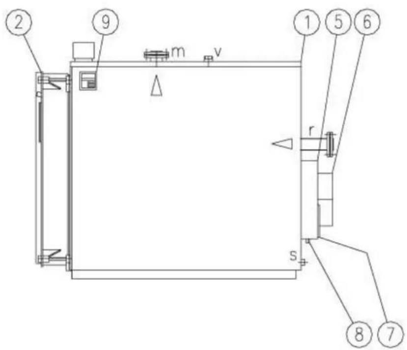
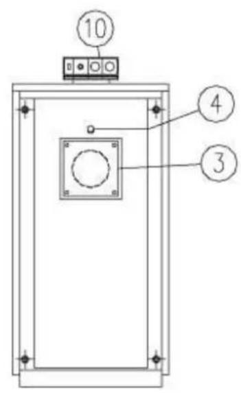
Fig.1
1 - Boiler body 8 - Flue condensate discharge
2 - Door 9 - Data badge
3 - Burner mounting plate 10 - Control panel
4 - Viewing port r - Return connection
5 - Flue collector m -Flow connection
6 - Flue connection s - Drain point
7 - Clean-out port v - Safety valve connection
Clearances
Sufficient space must be allowed as necessary at the rear of the boiler for connection of the flue components and access to the flue collector hood clean-out port.
A minimum of 450mm must be allowed at either side of the boiler/s with attention being paid to the space required to fully open the combustion chamber door with the burner mounted upon it.
Clearance at the front of the boiler must allow for cleaning of the flue tubes which run horizontally for the entire length of the boiler minus the thickness of the combustion chamber door and the depth of the flue collector hood. The clearance required at the front, measured from the front of the boiler body (excluding the door) must not be less than dimension L1 in the following tables.
Dimensions
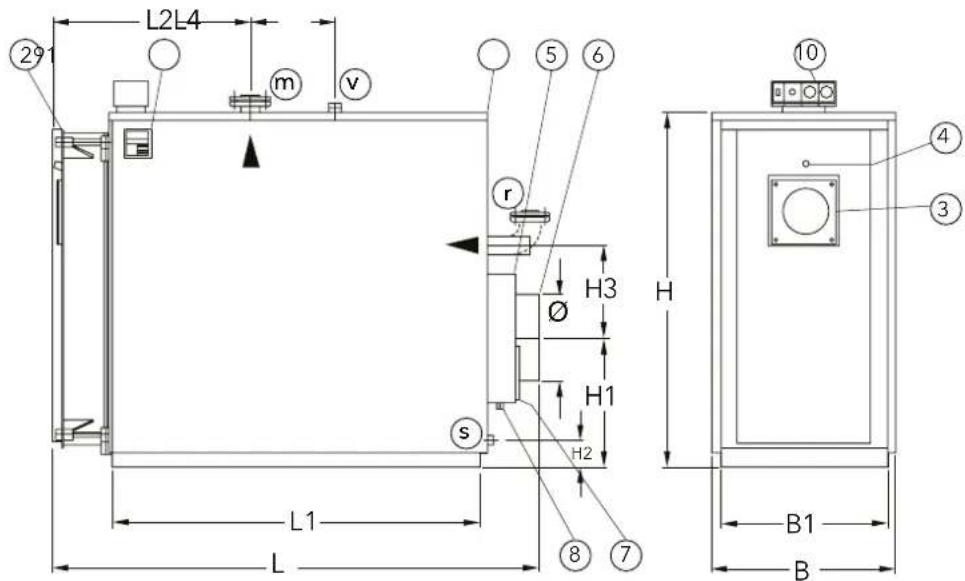
| Model Ecocond | 110 150 190 230 290 345 440 520 580 640 | ||||||||||
| Dimensions | B mm 660 660 740 740 740 740 870 870 870 | ||||||||||
| B1 mm 620 620 700 700 700 700 830 830 830 | |||||||||||
| L mm 1430 1680 1750 1750 2000 2000 2090 2390 2390 2390 | |||||||||||
| L1 mm 1010 1260 1260 1260 1510 1510 1512 1812 1812 | |||||||||||
| L2 mm 760 910 960 960 1110 1110 1100 1250 1250 | |||||||||||
| L4 mm 140 140 200 200 200 200 200 200 200 200 | |||||||||||
| H mm 1150 1150 1300 1300 1300 1300 1550 1550 1550 1550 | |||||||||||
| H1 mm 300 300 330 330 330 330 400 400 400 400 | |||||||||||
| H2 mm 50 50 50 50 50 55 55 55 55 | |||||||||||
| H3 mm 200 200 240 240 240 240 285 285 285 | |||||||||||
| Connections | r / m DN 2" | 2" | 65 65 65 80 80 80 80 | ||||||||
| v DN | 114" | 114" | 112" | 112" | 112" | 112" | 2" | 2" | 2" | 2" | |
| s DN | 32" | 34" | 34" | 34" | 34" | 34" | 34" | 34" | 34" | 34" | |
| ∅ mm 200 200 250 250 250 250 300 300 300 300 | |||||||||||
Handling / Scope of Supply
The Ecocond boilers are supplied with the control panel, insulating blankets, ceramic fibre packing material (for sealing around the burner blast tube) condensate neutralizing vessel and documentation packed inside the combustion chamber. The casing and burner assembly are supplied in separate cartons.
The boilers are equipped with lifting eyes to assist with the moving and handling of the boiler body.
Installation
Location
The location chosen for the installation of the boiler/s must be flat and level to facilitate correct alignment of connections and must be capable of supporting the units when full of water.
The floor or plinth must be fireproof in accordance with BS 6644.
The plant room must have sufficient space for the installation of the boilers, associated pipework, pumps, controls, flues, ventilation and with due allowance to access and servicing of other pieces of equipment.
Adequate space must be provided around the boiler to allow the removal of the burner and opening of the combustion chamber door.
Combustion chamber door opening and adjustment
The boiler is supplied with the door opening front left to right; it is possible to reverse the opening.
To open the door, remove the fixing nuts from the left hand side.
To reverse the direction of opening of the combustion chamber door it will be necessary due to the size and weight of door to utilise lifting gear.
- Attach lifting gear via the two holes in the upper part of the door assembly.
- Remove the 4 door retaining nuts
- Carefully remove the door assembly and set to one side
- Remove the two locknuts nuts from the tie rods on the left hand side and transfer them to the rods at the right hand side (positioning them approximately the same as when on the left hand tie rods).
- Carefully offer up the door assembly and remount onto the tie rods and retain using previously removed nuts. Release and remove any lifting aids/equipment.
To adjust and tighten the door:
- Slightly slacken back the locknuts.
- Tighten the door evenly onto the front of the boiler body using the door retaining nuts/capstans to form a gas tight seal.
- Re-tighten as necessary the locknuts back against the bush seating on the door assembly.
- Proceed to mount the burner, following which, check and adjust as necessary, the fitting of the combustion chamber door against the boiler body
Burner mounting
Follow carefully the instructions supplied with burner.
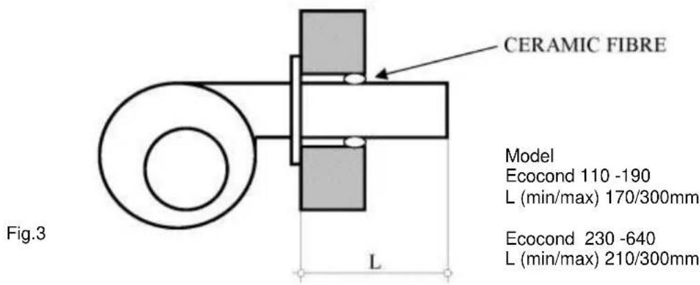
The burner mounting plate must be cut and drilled as appropriate to the dimensions of the burner to be utilised. It is extremely important that any space around the burner blast tube is packed with the ceramic fibre material supplied with the boiler. The burner blast tube length "L" must be within the range shown below.
Minimum return temperature (for oil fired installations)
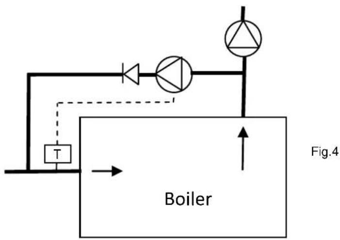
To avoid the risk of flue gas corrosion due to sulphur in the oil fuel, it is most important to ensure that the return water temperature entering the boiler is maintained above 40^ C. An acceptable method of creating of this facility is to install a link pipe between the main flow and return pipes serving the boiler, with a pump and a non-return valve included (as shown above). The pump needs only to be of a very low head and the flow rate should be in the order of 25-30% of the mass flow of the main boiler pump. The pump should be controlled by a thermostat mounted onto the return pipe adjacent to the return pipe connection of the boiler and the temperature setting should be nominally 40^ C for oil firing.
Fuel supply
Gas supply pipework must be in accordance with BS 6891 or IGE/UP/2
The gas installation must be soundness tested to and purged in accordance with BS 6891 or IGE/UP/1 & IGE/UP/1A.
Gas connections to the burner shall not be smaller than the connection size on the burner. If a gas pressure booster is required (refer to the manual supplied with the burner), then the controls must include a low gas pressure cut off device at the inlet to the booster. It may be necessary to install a governor between the booster and the burner gas train should the inlet pressure to the gas train exceed 50mbar.
The oil storage and supply system should be designed and installed in accordance with BS.5410 Part 2. If liquid bio fuel is being used, ensure all components are suitable for such use. Liquid bio fuel must be in accordance with BS EN 1423.
The oil supply pipe between storage tank and burner should be installed using copper, steel or aluminium pipe and fittings. Galvanised pipes are not considered suitable. The oil supply pipe should terminate adjacent to the burner with an isolating valve and should include metal bowl type filter.
Mounting the control panel.
The control panel is delivered packed inside the combustion chamber.
Mount the control panel onto the top boiler casing panel using the fixings provided.
The instrument capillaries must be carefully extended and located into the thermostat pockets adjacent to the flow pipe assembly on the boiler body.
Care must be taken to ensure that electrical cables and thermostat capillaries are not routed as to be in contact with the hot parts of the boiler body.
Flue system
Ecocond boilers are suitable for open flue type installations B_23 taking air for combustion from the room in which it is installed; the boiler plant room must be suitably ventilated. The flue pipe and components serving the Ecocond boiler must be suitable for use with condensing appliances and should have a fall back towards the boiler of not less than 3^ to ensure that any condensation that forms within the chimney is free draining back to the boiler.
The route of the flue short be as short as possible and sized appropriately to ensure complete evacuation of combustion gases without causing excessive back pressure. The flue should generate sufficient draught to overcome its own resistance with a minimum negative draught at the boiler flue connection in the order of 10 – 30Pa. The flue installation should comply with the requirements of the Clean Air Act 1956, BS 6644, BS5440 and IGE/UP/10 as applicable.
Optional flue gas condensation neutralising device.
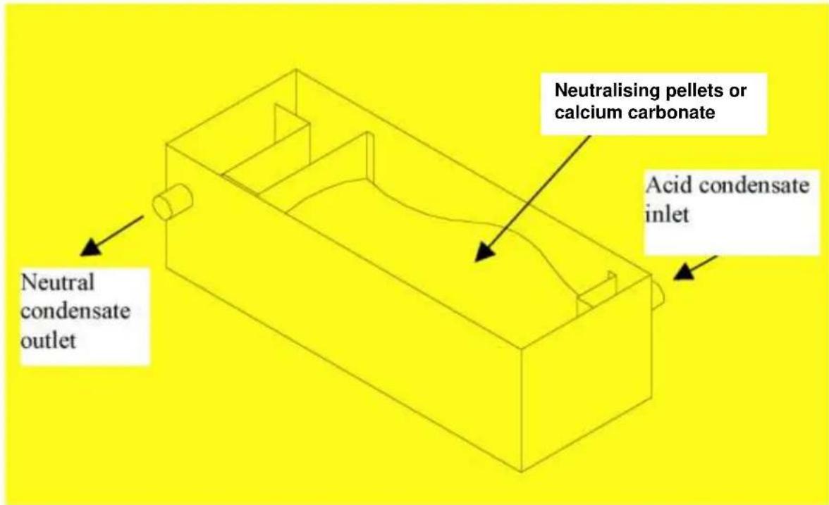
Available as an optional extra device, is the supply of a boiler condense receptacle which may be filled with neutralising pellets or calcium carbonate. Fill the device approximately half way up and refill when the residue level reaches less than 30mm.
Use the supplied hose to connect the condensation waste outlet of the flue collector (see item 8 Fig.1 on page4) to the neutralising device.
System water
Care must be taken to ensure that system pipe work is cleansed and flushed prior to filling the boiler.
The system water must be treated with a good quality corrosion inhibitor and the water condition must be maintained to ensure that the following values are observed:
pH 8.3-9.5
Hardness <100mg CaCO3/litre
Chlorides <50mg/litre
Oxygen <0.1mg/litre
Phosphates <30/mg/litre
It is strongly recommended to install coarse strainers to protect the boiler, pumps, valves etc from the effects of solid debris or particles within the system
Control panel schematic
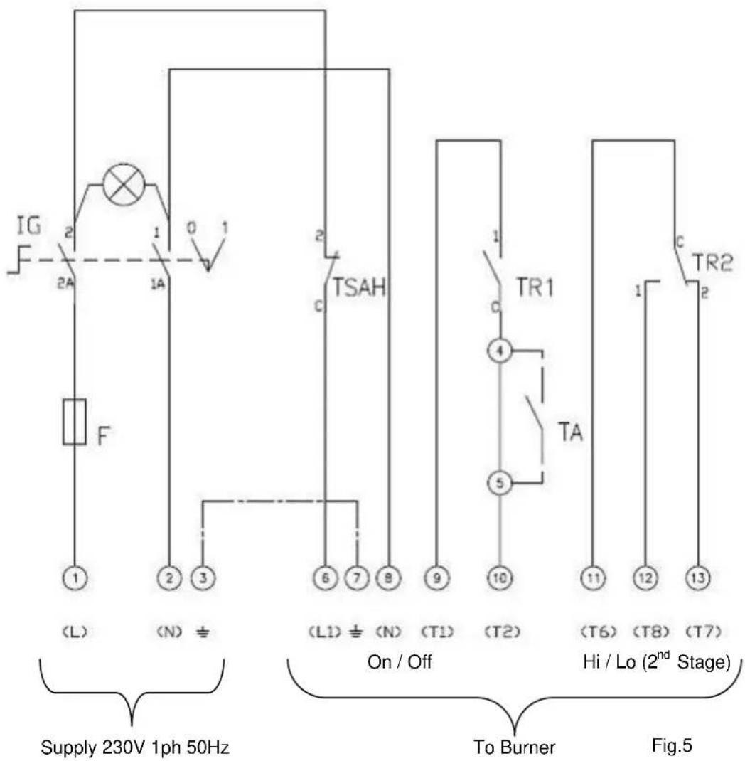
Preliminary checks before first firing
- Check that control panel instrument bulbs are correctly positioned in the thermostat pockets.
- Ensure that the flue tube turbulators do not protrude from the front of the tubes and that no foreign objects are within the combustion chamber.
- Check that any gaps between the burner blast tube and the combustion chamber door have been filled using high temperature ceramic fibre material.
- Check that the system has been filled with water and is vented and that the pressure is above 1 bar and within the maximum limits of the plant.
- Ensure that an appropriately rated safety relief valve has been fitted and where necessary a pressure limiter.
- Check that combustion chamber door has been closed correctly.
- Check that pumps rotate freely and in the correct direction.
- Check fuel supplies have been appropriately tested for soundness, have been purged/vented and the fuel control valve is closed. Ask to view certificates. Gas supplies should be tested and purged in accordance IGE/UP/1 or IGE/UP/1A as appropriate
- Check that the ventilation provision meets with the appropriate standards.
- Check that the power supply is of the appropriate rating and adequately fused and that an isolator is positioned adjacent to the boiler.
- Ensure a heat load is available.
- Check that flue pipe is securely connected /sealed onto appliance
First start up
• Refer to the instructions supplied with the burner
- Check that appropriate sized nozzles have been fitted (oil fired burner).
- Check security and condition of flexible fuel lines (oil fired burner).
- Check electrode condition, positioning and gaps as specified in the burner manufacturer's instructions
• Make burner pre-settings for head positioning and air settings
- Attach oil pressure gauge to burner oil pump (oil fired burner).
- Ensure temperature controls are calling for heat
- Turn on fuel supply at isolating valve
- Turn on boiler at isolator and on/off on boiler control panel – the burner should start its start-up and ignition process.
- Check gas train (gas burner) and any pipework between isolating valve and burner connection for leakage.
- Check oil lines / oil connections for soundness (oil burner).
- Adjust burner in accordance with the burner manufacturer's instructions and allow the burner to stabilise for approximately 10 – 15 minutes; following which take measurements of combustion gases, fuel throughput (gas burner) and making any further adjustments as necessary. Record measurements.
- Switch off boiler, remove any gauges and refit test points.
- Restart/stop boiler several times to check integrity of ignition system.
- Check combustion chamber door for correct sealing.
- Check flue joints for integrity.
- Check water connections for soundness.
- (For gas fired burner only), with burner firing, turn off gas supply and ensure burner goes to lockout. Wait 45 seconds, turn on gas supply, and press reset button on burner – ensure burner restarts normally.
- Set controls to normal operational settings.
- Instruct user on the operation of the boiler and its controls and safety functions.
User Instructions
- Following the successful installation and commissioning procedures, the user must be made aware of the lighting and operating instructions including a practical demonstration.
- This installation guide plus the burner instructions must handed over for safe keeping and future reference.
Operation / Controls
- The control panel includes two control thermostats which allows for the operation of high / low firing (2 stage burners).
- The left hand thermostat is for the control of the first stage (low fire) and should be set to the actual final wanted flow temperature; the right hand thermostat is for the control of the second stage (high fire) and should be nominally set around 3-5 degrees lower than the first stage thermostat to allow the burner to reduce to it's low fire setting as the final setpoint water temperature is approached.
- Care should be taken to ensure that the controls are set to avoid that the water temperature within the system remains at a level where the return water temperature is less than 40^ C for oil firing.
- If a modulating burner is being used, then the 4 core burner connection lead (T6,T8,T7) should be ignored and not utilised. The thermostat sensing bulb for the 2^nd stage control thermostat should not be located in the thermostat pocket, and the temperature sensor supplied with the modulating burner temperature controls can be substituted into the thermostat pocket in place of the 2^nd stage thermostat sensing bulb.
Elco Heating Solutions Limited
3 Juniper West, Fenton Way, Southfields Business Park,
Basildon, Essex SS15 6SJ
Tel: 01268 546700 Fax: 01268 888250
www.olco.co.uk
- CONTENTS
- General Description
- Connections etc
- Clearances
- Dimensions
- Handling / Scope of Supply
- Installation
- Location
- Combustion chamber door opening and adjustment
- Burner mounting
- Fuel supply
- Mounting the control panel.
- Flue system
- Optional flue gas condensation neutralising device.
- System water
- Control panel schematic
- Preliminary checks before first firing
- First start up
- User Instructions
- Operation / Controls
Brand : Elco
Model : ECOCOND
Category : Water heaters