
ERX-900-TFT - Uncategorized Toorx - Free user manual and instructions
Find the device manual for free ERX-900-TFT Toorx in PDF.


| Product Type | Elliptical Cross Trainer |
| Brand | Toorx |
| Model | ERX-900-TFT |
| Dimensions (L x W x H) | 130 x 65 x 170 cm |
| Product Weight | 55 kg |
| Maximum User Weight | 120 kg |
| Power Supply | AC adapter (Input 100-240V, Output 6V DC) |
| Display Type | 7-inch TFT color screen |
| Resistance System | Magnetic, 16 levels |
| Flywheel Weight | 7 kg |
| Stride Length | 40 cm |
| Heart Rate Monitoring | Hand grip pulse sensors + Bluetooth chest strap compatible |
| Programs | 24 preset programs, user-defined, body fat test |
| Connectivity | Bluetooth 4.0 (compatible with Zwift, Kinomap) |
| Speakers | Built-in 2W x 2 stereo speakers |
| Fan | Yes, adjustable cooling fan |
| Transport Wheels | Yes, front transport wheels |
| Leveling Feet | Yes, adjustable for stability |
| Maintenance | Lubricate slide rails every 3 months; check bolts regularly |
| Safety Features | Emergency stop key, stable base, no pinch points |
| Spare Parts Availability | Pedals, handlebars, console, power adapter via authorized dealers |
| Warranty | 2 years parts and labor |
Frequently Asked Questions - ERX-900-TFT Toorx
User questions about ERX-900-TFT Toorx
0 question about this device. Answer the ones you know or ask your own.
Ask a new question about this device
Download the instructions for your Uncategorized in PDF format for free! Find your manual ERX-900-TFT - Toorx and take your electronic device back in hand. On this page are published all the documents necessary for the use of your device. ERX-900-TFT by Toorx.
USER MANUAL ERX-900-TFT Toorx
APP
READY 3.0
ERX900
TFT
i
B Front stabilizer

D Console supporting tube

C Rear stabilizer
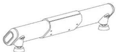
Front pedal supporting tube cover

E
E1 Handle bar (L)
Console supporting tube cover (L&R)

/ Adaptor
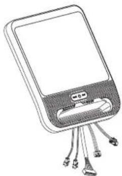
G Console (G1)
&Console cover (G2)


Pedal supporting tube cover (L1&L2),(R1&R2)
Central supporting tube F

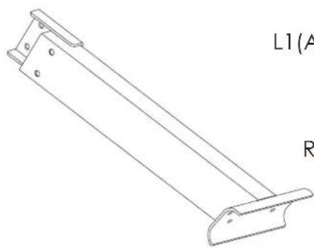
L1(A72)
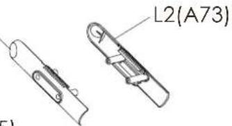
R1(A75)
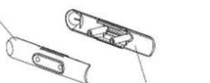
R2(A74)
PARTS LIST
(F4) Screw M8

(F2) Screw M8x65 (A107) Bolt ∅15x50.5
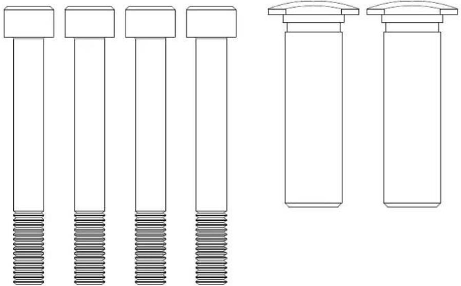
(F3) Washer M8
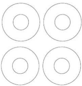
(A78) Screw M3x20

(A62) Spring washer M8
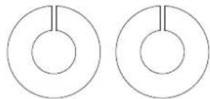
(A61) Washer M8
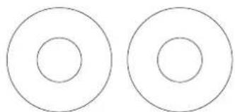
(A63) Screw M8x20

TOOL

FIGURE1
FIGURE 1__ FRONT STABILIZER (B) ASSEMBLY
Step 1. Remove the four preassembled screws (B3), spring washer (B4) and washer (B5) from the front stabilizer (B).
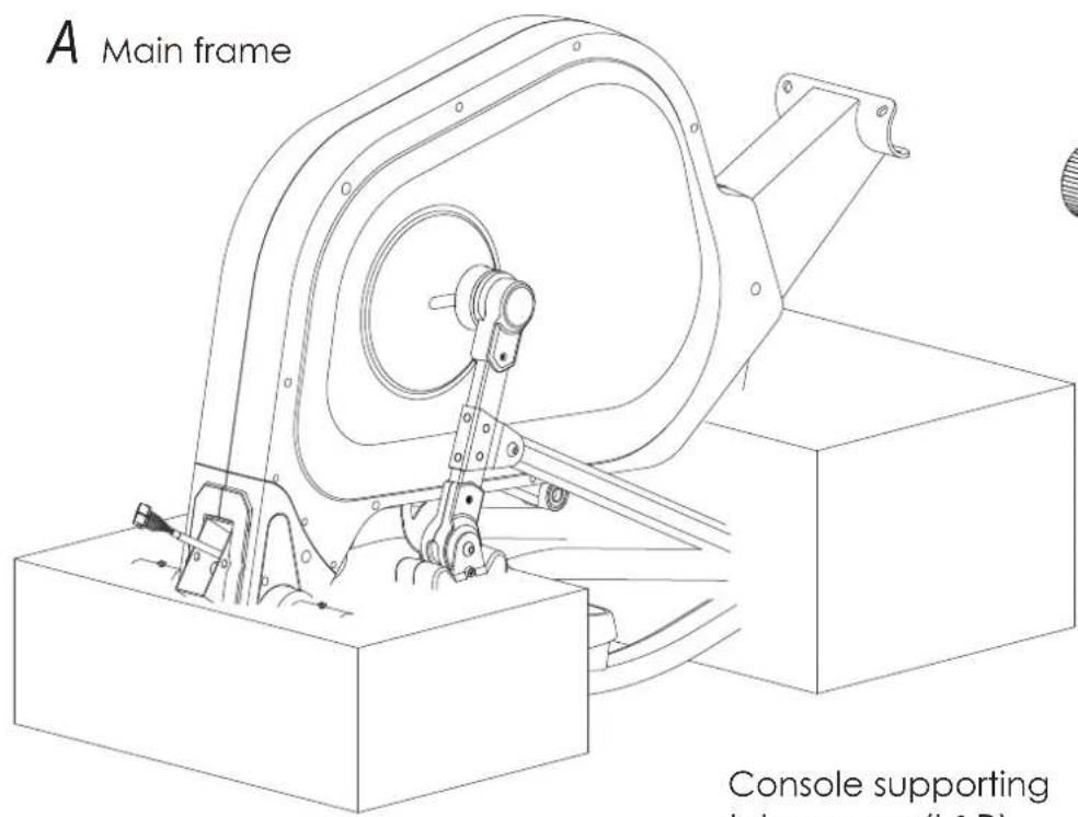
Step 2. Attach the front stabilizer (B) on to main frame (A) with screws (B3), spring washer (B4) and washer (B5).
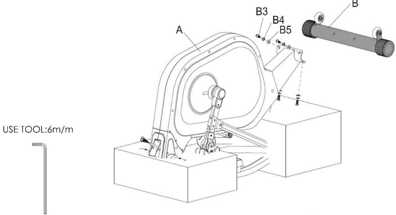
FIGURE 2
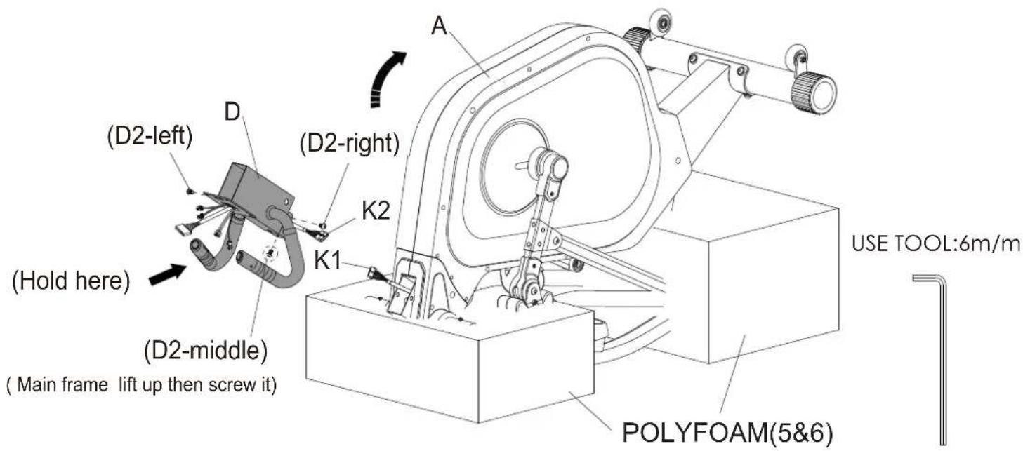
FIGURE 2__ CONSOLE SUPPORTING TUBE (D) ASSEMBLY
Step 1. Remove the three preassembled screws (D2) from the console supporting tube (D).
Step 2. Connect console wire (K1&K2).
Step 3. Attach the console supporting tube (D) on to main frame (A) with screw (D2-left) and screw (D2-right).
Step 4. Use two hands to hold small handle bar to lift up the main frame (A). then finish the screw (D2-middle) assembly.
Step 5. Remove the bottom polyfoam pieces #5 & #6.
FIGURES CENTRAL SUPPORTING TUBE (F) ASSEMBLY
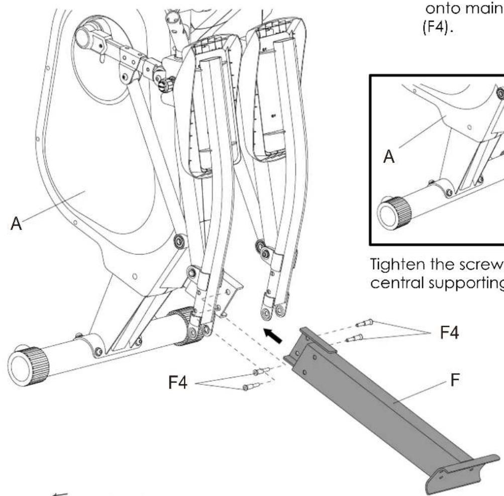
Step 1. Attach the central supporting tube (F) onto main frame (A) with four screws (F4).
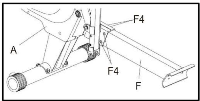
Tighten the screws (F4) on the central supporting tube when the unit is lifted.
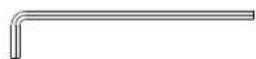
USE TOOL:6m/m
FIGURE 4
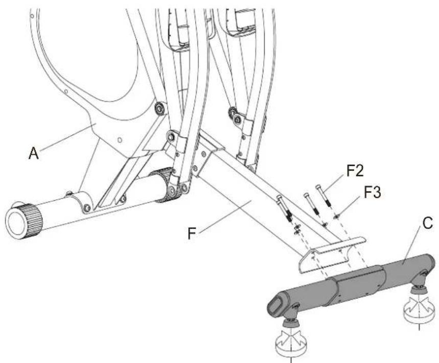
FIGURE 4__ REAR STABILIZER (C) ASSEMBLY
Step 1. Attach the rear stabilizer (C) onto the central supporting tube (F) with four screws (F2) and washer (F3).
Step 2. Adjust the stabilizer feet on the bottom rear stabilizer (C) to level the machine.
USE TOOL:6m/m
FIGURES_
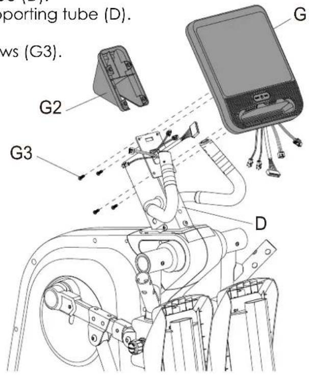
CONSOLE & CONSOLE COVER ASSEMBLY
Step 1. Remove four screws (G3) from the console (G).
Step 2. Connect all wires.
Step 3. Fit the console (G) to console supporting tube (D).
Step 4. Slide the console cover (G2) on console supporting tube (D).
Step 5. Screw console, console supporting tube (D) and console cover (G2) together using screws (G3).
USE TOOL:

FIGURE 6
FIGURE 6__ CONSOLE SUPPORTING TUBE COVER (L&R) ASSEMBLY
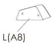
Step 1. Attach the console supporting tube cover-L (A8) and console supporting tube cover-R (A9) using screws (A78).
USE TOOL:

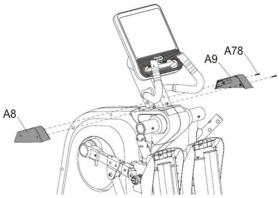
FIGURE7_
FRONT CONNECTING SHAFT (A53) & FRONT PEDAL SUPPORTING TUBE-L&R (A64&A65) ASSEMBLY
Step 1. Attach front connecting shaft (A53) and front pedal supporting tube-L (A64) using bolt (A107), screw (A63) spring washer (A62) and washer (A61).
** Repeat same step to finish right side assembly.

USE TOOL:6m/m

FIGURE 8
FIGURE 8__ PEDAL TUBE COVER-(L&R) ASSEMBLY
Step 1. Fit the pedal tube cover-L1 (A72) and pedal tube cover-L2 (A73) to the front pedal supporting tube-L (A64) using the two screws (A78).
** Repeat same step to finish right side assembly.
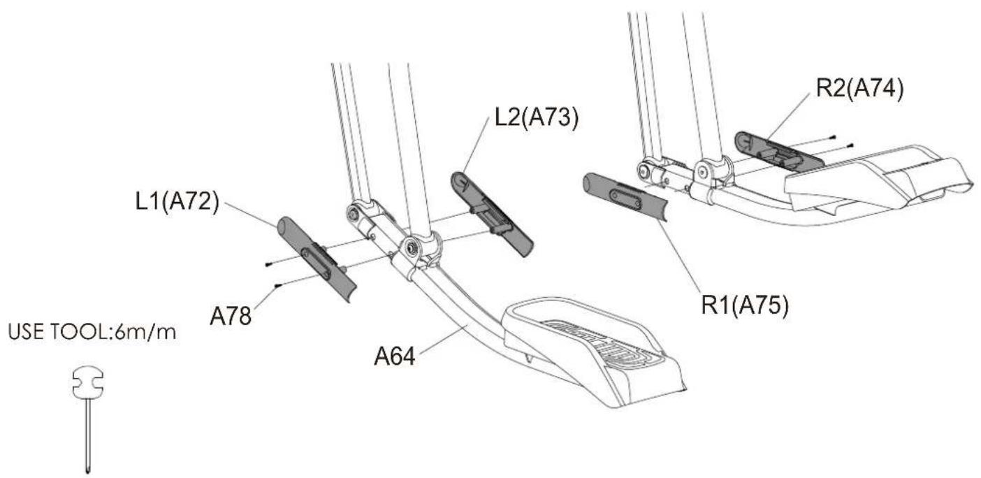
FIGURE9
FIGURE 9 — HANDLE BAR & FRONT PEDAL SUPPORTING TUBE COVER ASSEMBLY
Step 1. Remove the six preassembled screws (E4&E5) from the handle bar (E1).
Step 2. Remove the two preassembled screws (A108) from the main frame (A).
Step 3. Mount the handle bar (E1) onto the main frame (A) with screws (E4&E5).
Step 4. Mount the front pedal supporting tube cover (A66&A67) onto the main frame (A) with two screws (A108).
**Repeat same step to finish right side assembly.
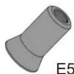
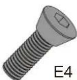


FIGURE 10
FIGURE 10__ ADAPTER ASSEMBLY
Attach one end of the adapter into the power socket and the other end into the input jack on the main frame like shown.

FIGURE11 _ HOW TO TRANSPORT THE MACHINE
If the machine needs to be transported to a different location, lift up the rear stabilizer until the front transportation wheels engage the ground. You may now move the machine to the desired location. After the move, gently set the machine down at its new location and adjust the levelers on the bottom rear stabilizer to level the machine if needed.
WARNING: Never attempt to lift the machine by yourself, ask for additional help if needed and never attempt to lift the machine if you have any medical issues.

FIGURE 12 — HOW TO USE TOGGLE SWITCH TO ADJUST THE RESISTANCE
When the console is powered on, you may press the toggle buttons on the small handlebar to adjust the resistance: Press "+LOAD" button on the right side to increase resistance and press "-LOAD" button on the left side to decrease resistance.

HOW TO ADJUST THE STRIDE
Step 1. There are 2 different stride choices on the 1280ef. They are 17" and 22".
(When you choose 17", you will see the orange sticker on front pedal supporting tube, when you choices 22", you will see the white sticker on front pedal supporting tube.)
Step 2. Loosen the knob and pull out to adjust the stride length as you desire.
Step 3. After selecting the stride length, screw the knob back in tightly.
Step 4. Repeat this to adjust the stride length for the other side.
WARNING: NEVER adjust the stride length while standing on the machine.
Always adjust both the right and left stride to the same setting. Uneven positions is never recommended and dangerous.

**Please loosen the knob first, then pull out and hold the pedal at the same time by moving pedal up/down to adjust the desired stride length.
CONSOLE DISPLAY
10.1" TFT
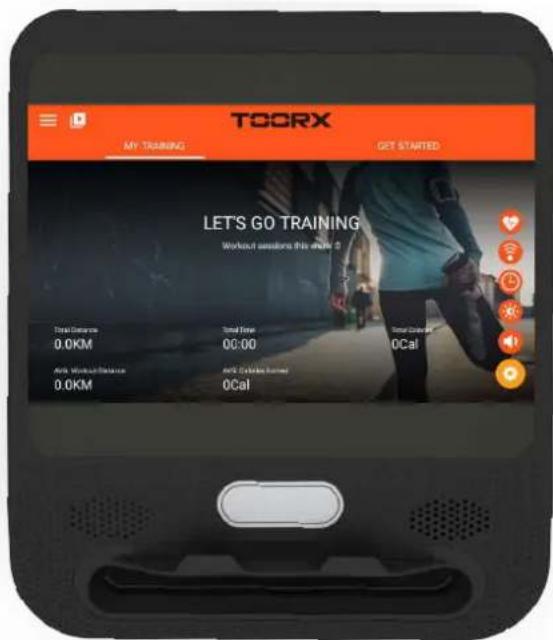
Step-by-Step Instructions
- Power-up
Press the Quick Start Button to turn on the console.

Fig 1. TURN-ON DISPLAY
After a while, the display will turn into Home Screen. Please check Figure 2.
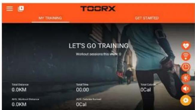
Fig 2. Home Screen
*** Notice that if the console has already been opened, it will turn from black screen into Home screen directly after you press the Quick Start Button.
INSTRUCTION MANUAL
1. POWER ON (Home page):

2. Function Spec Description:
A. MY TRAINING: Displays total workout data
B. GET STARTED:
QUICK START / INTERVAL / MAP YOUR ROUTE / Constant Power/Programs/Heart rate Control/FTMS
-
Total six modes of workout for choose
-
FTMS : to turn on the FTMS Bluetooth connection
C. System Setting ≡: This page can operate login account/home page/historical data/new linked account/Settings and other functions
D. Volume control:

E. Brightness adjustment function:

F. Time zone selection :
G.WIFI setting function :

H. Bluetooth heartbeat matching function:

I. Multimedia mode :

START/PAUSE: When in starting status press this key, it will stop training, and when in stopping mode press this key it will start to work.
STOP: Press this key stop training.
UP: Switch knob to increase the load level.
DOWN: Switch knob to decrease the load level.
A. LOGO IN: (photo) Personal information login and create, login account (Email application, FB, We Chat, GOOGLE login)
B. HOME: Back to home page
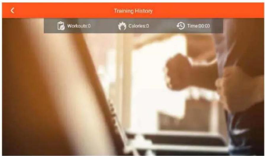
C.TRAINING HISTORY: Exercise information enquiry (login required)
D. SETTING: Setting mode
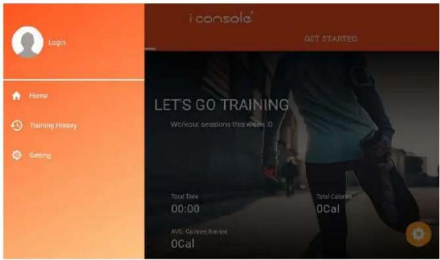
A. Click Logo in (photo) to login the account, select face book /GOOGLE/ We Chat / enter the email password to log IN.

B. TRAINING HISTORY
C.SETTING:
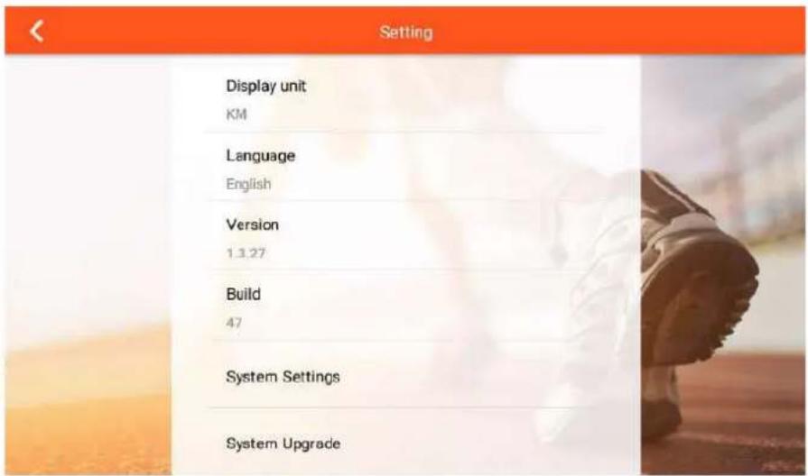
Click SYSTEM SETTINGS to enter into system setting (wifi, brightness, volume, BT, Language, KM/ML)

- Multimedia mode (slide the page left and right to select the APP icon you want to use):
In Multimedia mode, user can press “ ” to display or hide the movement value, press “ ” back to the last system function page., press “ ” to the home page, press “ ▶ “to start training ,press” □ “ stop exercise.
7、Function Introduction
Quick Start / Interval /Map Your Route/Constant Power/Programs/Heart rate Control/FTMS


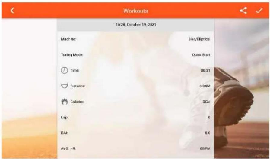
A. QUICK START MODE:
- Setting the exercise value (DIST/TIME/CAL), Press "START" go to training, data start to counting.
- When start training can adjust the LEVEL UP&DOWN, press "PAUSE" enter into break mode, press "STOP" to exit this mode.
C. When finished, the SUMMARY displays.


B. INTERVAL MODE:
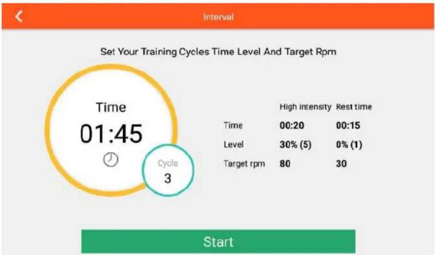
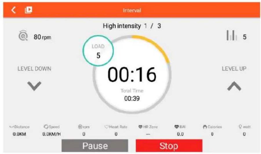
A. Can set the functions value of CYCLE /TIME /LEVEL /TARGET RPM separately, press "START" go to training.
B. Warm up first, then start INTERVAL mode
C. In high intensity time can adjust the load level (display the level as set)
When in rest time adjust the load level, keep display the level as set.
D. Press "PAUSE" enter into break mode, press "STOP" leave this mode.
E. When finished, the SUMMARY displays.


C.MAP YOUR ROUTE MODE:
- After entering this mode, it will detect the current region, click “☐” load the preset link, distinguish Chinese and non-Chinese region.; click “☐” can switch to the world map (GOOGLE MAP) or China Map. preset “☐” as the map of China, and “☐” as the World map.
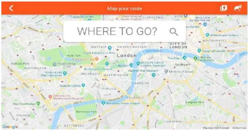
- Planning the map road, long press one time will display the start position “☐”, long press two times will display the final position “☐”, press three times display the turning point “☐” (with the max qty).
Slide and start training, press " " can reset the map.
-
Press “ ” display or hide the exercise value, press “ ” switch the map/ Google street / satellite mode, and display the map/ Google street / satellite p113s in cycle. Also user can adjust the LEVEL/INCLINE/FAN, LEVEL will be adjusted according to the slope map.
-
Can adjust the LEVEL UP OR DOWN, press “ “go to break mode, press “ □” leave this mode.
-
When finished, the SUMMARY displays.


D、Constant Power MODE:
- User can set TIME/TARGET POWER, then press "START" go to training.
- LEVEL will be adjusted according to the value of WATT.
- Press “ START/PAUSE 📄 ”go to break mode, press “ STOP ☐ “ leave this mode.
- When finished, the SUMMARY displays.


E. PROGRAMS MODE:
- Set the TIME and select P1\~P12 PROGRAM, press "START" go to training.
- When start user can adjust the LEVEL UP&DOWN, level will be adjusted according to the PROGRAM.
- Press "PAUSE" enter into break mode, press "STOP" leave this mode.
- When finished, the SUMMARY displays.
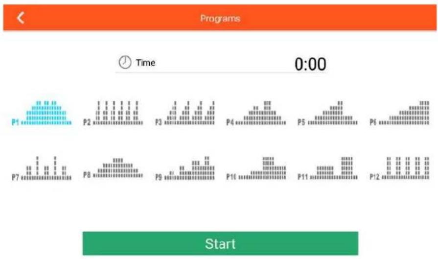

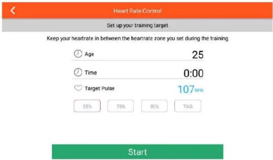
F. HEART RATE CONTROL MODE:
- User can set the AGE/TIME/TARGET 55% 75% 90% TAG PULSE, press "START" go to training.
- LEVEL will be adjusted according the goal value of heart rate, if not reached the goal value, the load level will increase, if over the goal value level will decrease automatically.
- If without heart rate input about 30s, it will exit this mode automatically.
- Press "PAUSE" enter into break mode, press "STOP" leave this mode.
E. When finished, the SUMMARY displays.
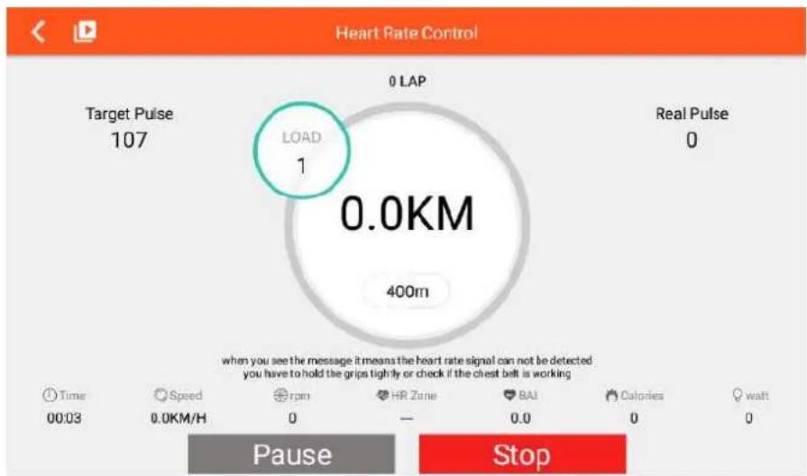
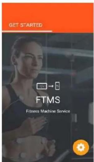
G. FTMS:
- User can press "ON" to turn on the FTMS Bluetooth connection.
- Once the FTMS in on, the logo will become blue.



Garlando
GARLANDO SPA
Via Regione Piemonte, 32 - Zona Industriale D1
15068 - Pozzolo Formigaro (AL) - Italy
www.toorx.it - info@toorx.it
- ERX900
- TFT
- PARTS LIST
- FIGURE1
- FIGURE 1__ FRONT STABILIZER (B) ASSEMBLY
- FIGURES CENTRAL SUPPORTING TUBE (F) ASSEMBLY
- FIGURE 4
- FIGURE 4__ REAR STABILIZER (C) ASSEMBLY
- FIGURES
- CONSOLE & CONSOLE COVER ASSEMBLY
- FIGURE 6__ CONSOLE SUPPORTING TUBE COVER (L&R) ASSEMBLY
- FIGURE7
- FRONT CONNECTING SHAFT (A53) & FRONT PEDAL SUPPORTING TUBE-L&R (A64&A65) ASSEMBLY
- FIGURE 8__ PEDAL TUBE COVER-(L&R) ASSEMBLY
- FIGURE9
- FIGURE 9 — HANDLE BAR & FRONT PEDAL SUPPORTING TUBE COVER ASSEMBLY
- FIGURE 10__ ADAPTER ASSEMBLY
- FIGURE11 _ HOW TO TRANSPORT THE MACHINE
- FIGURE 12 — HOW TO USE TOGGLE SWITCH TO ADJUST THE RESISTANCE
- HOW TO ADJUST THE STRIDE
- CONSOLE DISPLAY
- STEP-BY-STEP INSTRUCTIONS
- POWER-UP
- INSTRUCTION MANUAL
- POWER ON (HOME PAGE)
- FUNCTION SPEC DESCRIPTION
- C.SETTING
- 7、FUNCTION INTRODUCTION
- QUICK START MODE
- INTERVAL MODE
- C.MAP YOUR ROUTE MODE
- D、CONSTANT POWER MODE
- PROGRAMS MODE
- HEART RATE CONTROL MODE
- FTMS
- GARLANDO
Brand : Toorx
Model : ERX-900-TFT
Category : Uncategorized