
CMMT-AS-C18-11A-P3-MP-S1 - Uncategorized Festo - Free user manual and instructions
Find the device manual for free CMMT-AS-C18-11A-P3-MP-S1 Festo in PDF.


| Product Type | Servo drive with integrated safety sub-functions (STO, SBC, SS1-t) |
| Brand | Festo |
| Model | CMMT-AS-C18-11A-P3-MP-S1 |
| Safety Sub-Functions per EN 61800-5-2 | Safe Torque Off (STO), Safe Brake Control (SBC), Safe Stop 1 (SS1-t) with external safety relay |
| Safety Classification | Up to SIL 3, PL e (Cat. 4) for STO with two-channel wiring and STA evaluation; up to SIL 3, PL e for SBC with two brakes and SBA evaluation |
| Reaction Time | < 10 ms for STO and SBC request |
| Error Reaction Time (diagnostic outputs) | < 20 ms for STA and SBA |
| Logic Supply Voltage (nominal) | 24 V DC (PELV per EN 60204-1) |
| Input Voltage Range (#STO, #SBC) | -3 … 30 V DC |
| Diagnostic Outputs (STA, SBA) | Push-pull, 18…30 V DC, max 15 mA high level |
| Brake Output BR-EXT [X1C] | High-side switch, 18…30 V DC, max 100 mA |
| Degree of Protection | IP20 with mating plug and closed backwall; otherwise IP10 |
| Mounting Position | Vertical on closed surface, free convection |
| Ambient Temperature (operation) | 0…+40 °C nominal, up to +50 °C with derating |
| Service Life | 25000 h at rated load (S1), 50000 h at <50% load |
| Conformity | CE (EMC, Machinery, RoHS), UKCA, TÜV Rheinland certified |
| Maintenance | Maintenance-free during service life; cyclical test of SBC required every 24 h |
| Repair | Not permissible; replace complete device if defective |
Frequently Asked Questions - CMMT-AS-C18-11A-P3-MP-S1 Festo
User questions about CMMT-AS-C18-11A-P3-MP-S1 Festo
0 question about this device. Answer the ones you know or ask your own.
Ask a new question about this device
Download the instructions for your Uncategorized in PDF format for free! Find your manual CMMT-AS-C18-11A-P3-MP-S1 - Festo and take your electronic device back in hand. On this page are published all the documents necessary for the use of your device. CMMT-AS-C18-11A-P3-MP-S1 by Festo.
USER MANUAL CMMT-AS-C18-11A-P3-MP-S1 Festo
natural_image
Technical line drawing of an FESTO PLC internal unit with visible ports and wiring (no text or symbols beyond branding)FESTO
Manual | Safety sub-function | STO, SBC, SS1
8190324
2023-07f
[8190326]
Translation of the original instructions
ET 200SP, PNOZ, Pilz, SIEMENS are registered trademarks of the respective trademark owners in certain countries.
Table of contents
1 About this document.... 5
1.1 Target group....5
1.2 Applicable documents....5
1.3 Product version.... 5
1.4 Product labelling.... 5
1.5 Specified standards.... 5
2 Safety....5
2.1 Safety instructions....5
2.2 Intended use.... 6
2.2.1 Application areas....6
2.2.2 Permissible components....6
2.3 Foreseeable misuse....6
2.4 Training of qualified personnel....7
2.5 Product conformity.... 7
2.6 Safety engineering approval....8
3 Additional information....8
4 Product overview.... 8
4.1 Safety sub-functions....8
4.1.1 Function and application.... 8
4.1.2 Safety sub-function STO....8
4.1.3 Safety sub-function SBC....12
4.1.4 Safety sub-function SS1.... 16
4.1.5 Cross wiring of several servo drives.... 20
4.1.6 Fault exclusion....20
4.1.7 Safety relay unit.... 21
4.1.8 Interfaces of the PDS.... 21
5 Installation.... 22
5.1 Safety.... 22
5.2 STO installation.... 23
5.3 SBC installation.... 24
5.4 SS1 installation.... 26
5.5 Installation for operation without safety sub-function.... 26
6 Commissioning....27
6.1 Safety.... 27
6.2 Check lists.... 27
7 Operation.... 30
8 Malfunctions....30
8.1 Diagnostics via LED.... 30
8.2 Repair.... 31
9 Technical data....31
9.1 Technical data, safety engineering....31
9.2 General technical data.... 35
9.3 Technical data, electrical.... 37
9.3.1 Motor auxiliary connection [X6B]. 37
9.3.2 Inputs, outputs, ready contact at [X1A]. 37
9.3.3 Inputs and outputs for the axis [X1C]. 41
1 About this document
1.1 Target group
The document is targeted towards individuals who mount and operate the product. It is additionally targeted towards individuals who are entrusted with the planning and application of the product in a safety-oriented system.
1.2 Applicable documents
This document describes the use of the safety sub-functions safe torque off (STO/Safe torque off) and safe brake control (SBC/Safe brake control) in accordance with EN 61800-5-2.
It is possible to implement the safety sub-function Safe stop 1 (SS1) with a suitable external safety relay unit and appropriate wiring of the servo drive.
- Observe the safety instructions in the documentation → Operating instruction Assembly Installation Safety sub-function.

All available documents for the product → www.festo.com/sp.
1.3 Product version
This documentation refers to the following version of the device:
- Servo drive CMMT-AS-...-S1, revision R01 and higher, see product labelling
1.4 Product labelling
Product labelling → Manual Assembly, Installation.
1.5 Specified standards
| Version | ||
| EN 61800-5-1:2007+A1:2017 EN 61508 Parts 1-7:2010 | ||
| EN ISO 13849-1:2015 EN 61800-2:2015 | ||
| EN 60204-1:2018 EN IEC 61800-3:2018 | ||
| EN 61131-2:2007 EN 61800-5-2:2017 | ||
Tab. 1: Standards specified in the document
2 Safety
2.1 Safety instructions
It is only possible to determine whether the product is suitable for specific applications by also assessing further components of the subsystem.
Analyse and validate the safety function of the entire system.
Safety
Check the safety functions at adequate intervals for proper functioning. It is the responsibility of the operator to choose the type and frequency of the checks within the specified time period. The manner in which the test is conducted must make it possible to verify that the safety device is functioning perfectly in interaction with all components. Time period for cyclical test 9.1 Technical data, safety engineering.
Prior to initial commissioning, wire the control inputs of the safety sub-functions STO and SBC. The safety sub-functions STO and SBC are available on the CMMT-AS on delivery without the need for any additional parameterisation.
Keep the documentation somewhere safe throughout the entire product lifecycle.
2.2 Intended use
The CMMT-AS-...-S1 supports the following safety sub-functions in accordance with EN 61800-5-2:
-Safe torque off (STO/Safe torque off)
-Safe brake control (SBC/Safe brake control)
- Safe stop 1 (SS1/Safe stop 1), achievable with suitable safety relay unit and appropriate circuitry of the servo drive
The safety sub-function STO is intended to switch off the torque of the connected motor, thereby preventing an unexpected restart of the motor.
The safety sub-function SBC is intended to safely hold the motor and axis in position at standstill.
The safety sub-function SS1 is intended for performing an emergency stop with subsequent torque switch-off.
2.2.1 Application areas
Safety sub-functions may only be used for applications for which the stated safety reference values are sufficient 9.1 Technical data, safety engineering.
2.2.2 Permissible components
The logic power supply must meet the requirements of EN 60204-1 (protective extra-low voltage, PELV).
If holding brakes and clamping units without certification are used, a risk assessment is required to assess their suitability for the related safety-oriented application.
In addition to the requirements of EN 60204-1, the following requirements apply to other components of the drive system from EN 61800-5-2:
- Annex D.3.5 and D.3.6 for motors
-Annex D.3.1 for motor and brake cables
-Annex D.3.4 for mating plugs
Components approved by Festo for the CMMT-AS fulfil these requirements.
2.3 Foreseeable misuse
Foreseeable misuse, general
- Use outside the limits of the product defined in the technical data.
-Cross-wiring of the I/O signals of more than 10 servo drives CMMT-AS.
-Use in IT networks without insulation monitors for detection of earth faults.
Safety
If the device is operated in IT networks, the potential conditions will change in the event of a fault (earth fault on the feeding mains supply). As a result, the rated voltage of 300 V to PE – which has important implications for the design of insulation and network disconnection – will be exceeded. This error must be detected.
-Use of a diagnostic output for connection of a safety function.
The diagnostic outputs STA and SBA are not part of the safety circuit. The diagnostic outputs are used to improve diagnostic coverage of the related safety sub-function. The diagnostic outputs may only be used in combination with the related safe control signals (AND operation) plus a reliable time monitoring function in the safety relay unit for the purpose of switching additional safety-critical functions.
Foreseeable misuse of the safety sub-function STO
- Use of the STO function without external measures for drive axis influenced by external torques. If external torques influence the drive axis, use of the safety sub-function STO on its own is not suitable for stopping the axis safely. Additional measures are required to prevent dangerous movements of the drive axis, such as use of a mechanical brake in combination with the safety sub-function SBC.
- Disconnection of the motor from the power supply.
The safety sub-function STO does not disconnect the drive from the power supply as defined by electrical safety.
Foreseeable misuse of the safety sub-function SBC
-Use of an unsuitable holding brake or clamping unit, also in view of:
-Holding or brake torque and emergency brake characteristics, if required.
-Frequency of actuation
-Use of an unsuitable logic voltage supply
2.4 Training of qualified personnel
The product may be installed and commissioned only by a qualified electrical engineer who is familiar with:
-Installation and operation of electrical control systems
-Applicable regulations for operating safety-related systems
Work on safety engineering systems may only be carried out by qualified personnel trained in safety engineering.
2.5 Product conformity
The product-relevant directives are listed in the declaration of conformity→ www.festo.com/sp.
Product conformity
| CE | in accordance with EU EMC Directivein accordance with EU Machinery Directivein accordance with EU RoHS Directive |
| UKCA | to UK EMC Regulationsto UK Supply of Machinery Regulationsto UK RoHS Regulations |
Tab. 2: Product conformity
i
The protection objectives of the Low Voltage Directive are fulfilled in accordance with the requirements of the EC Machinery Directive. The requirements of the Low Voltage Directive are based on the product standard EN 61800-5-1. The valid version of the product standard is listed in the declaration of conformity.
2.6 Safety engineering approval
The product is a safety device in accordance with the Machinery Directive. For details of the safety-oriented standards and test values that the product complies with and fulfils, see 9.1 Technical data, safety engineering.
3 Additional information
-Contact the regional Festo contact if you have technical problems www.festo.com.
4 Product overview
4.1 Safety sub-functions
4.1.1 Function and application
The servo drive CMMT-AS-...-S1 has the following safety-related performance features:
-Safe torque off (STO)
- Safe brake control (SBC)
- Safe stop 1 (SS1) with use of a suitable external safety relay unit and appropriate wiring of the servo drive
–Diagnostic outputs STA and SBA for feedback of the active safety sub-function
4.1.2 Safety sub-function STO
line
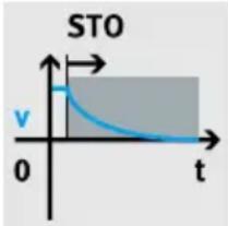
| t | v | | ---- | ----- | | 0 | 0.5 | | >0 | 0 |The function described here implements the safety sub-function STO according to EN 61800-5-2 (corresponds to stop category 0 from EN 60204-1).
The safety sub-function STO is used when the power supply to the motor needs to be switched off safely in the application but there are no further requirements for a targeted standstill of the drive (such as stop category 1 from EN 60204-1 → Safety sub-function SS1-t).
Function and application of STO
The safety sub-function STO switches off the driver supply for the power semiconductor, thus preventing the power output stage from supplying the energy required by the motor. The power supply to the drive is safely disconnected when the safety sub-function STO is active. The drive cannot generate torque and thus cannot perform any dangerous movements. With suspended loads or other external forces, additional measures must be put in place to prevent movements being performed (e.g. mechanical clamping units). The standstill position is not monitored in the STO state. The machines must be stopped and locked in a safe manner. This especially applies to vertical axes without automatic locking mechanism, clamping unit or counterbalancing.
NOTICE
If there are multiple errors in the servo drive, there is a danger that the drive will move. Failure of the servo drive output stage during the STO status (simultaneous short circuit of 2 power semiconductors in different phases) may result in a limited detent movement of the rotor. The rotation angle/travel corresponds to a pole pitch. Examples:
- Rotating motor, synchronous machine, 8-pin → Movement < 45° at the motor shaft
- Linear motor, pole pitch 20 mm → Movement < 20 mm at the moving part
Functional principle of STO
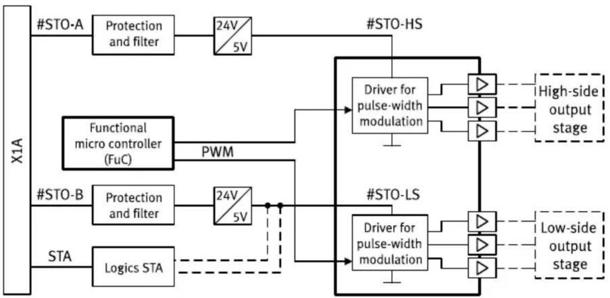
flowchart
graph TD
    subgraph X1A
        A["#STO-A"] --> B["Protection and filter"]
        B --> C["24V/5V"]
        D["Functional micro controller (FuC)"] --> E["PWM"]
        F["#STO-B"] --> G["Protection and filter"]
        G --> H["24V/5V"]
        I["STA"] --> J["Logics STA"]
    end

    subgraph #STO-HS
        K["Driver for pulse-width modulation"] --> L["High-side output stage"]
        K --> M["Low-side output stage"]
    end

    subgraph #STO-LS
        N["Driver for pulse-width modulation"] --> O["High-side output stage"]
        N --> P["Low-side output stage"]
    end

    A --> D
    B --> D
    C --> D
    E --> D
    G --> D
    H --> D
    J --> D
    J --> N
Fig. 1: Functional principle of STO
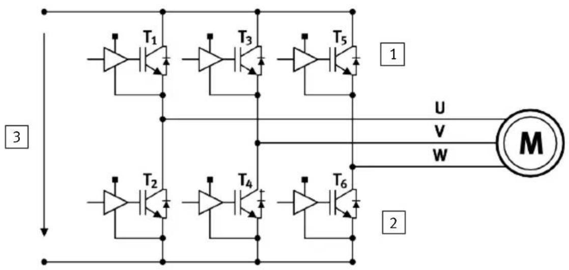
Fig. 2: Power stage with power transistors
1 High-side power stage
3 DC link voltage
2 Low-side power stage
STO request
The safety sub-function STO is requested on 2 channels by simultaneously switching off the control voltage at both control inputs #STO-A and #STO-B.
The drive responds as follows when the safety sub-function STO is requested:
- Response of the drive with a running motor: the movement of the drive is not decelerated via a braking ramp. The drive continues to move in an uncontrolled manner due to inertia or external forces until it comes to a standstill by itself.
- Response of the drive with a stopped motor: the drive is uncontrolled and can be moved by external forces.
STO feedback via STA diagnostic contact
The status of the safety sub-function STO can be reported to the safety relay unit via the STA diagnostic output.
The STA diagnostic output indicates whether the safe status has been reached for the safety sub-function STO. The STA diagnostic output switches to high level only when STO is active on 2 channels via the control inputs #STO-A and #STO-B.
| #STO-A #STO-B STA | ||
| Low level Low level High level | ||
| Low level High level Low level | ||
| High level Low level Low level | ||
| High level High level Low level |
Tab. 3: Level of STA
Product overview
If protective functions are triggered on both channels (STO-A and STO-B), e.g. if the voltage at STO-A and STO-B is too high, the internal protective functions switch off and STA also delivers a high level signal.
Recommendation: the safety relay unit should check the status of the diagnostic output whenever there is a request from STO. The level of STA must change according to the logic table. The safety relay unit can cyclically test the signals #STO-A and #STO-B for high level with low test pulses and for low level with high test pulses.
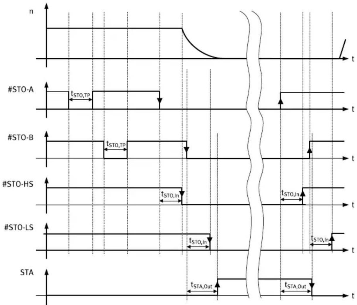
STO timing
other
| Signal | Time Segment | Duration Label | |------------|----------------------------------|----------------| | #STO-A | t_STO,TP | t_STO,TP | | #STO-B | t_STO,TP | t_STO,TP | | #STO-HS | t_STO,In | t_STO,In | | #STO-LS | t_STO,In | t_STO,In | | STA | t_STA,Out | t_STA,Out |Fig. 3: STO timing diagram
Legend for STO timing
| Term/abbreviation Explanation | |
| #STO-A/#STO-B 2-channel input for STO request | |
| #STO-HS/#STO-LS Internal triggering, pulse-width modulation driver high side/low side | |
| t_STO,TP | Length of low test pulses^1) at #STO-A/B |
| t_STO,In | Max. delay until STO switches off (≤ permissible reaction time when a safety sub-function is requested1) |
| STA Feedback, STO active | |
| t_STA,Out | Max. delay for diagnostic feedback (≤ permissible reaction time when a safety sub-function is requested1) + 10 ms) |
| n Rotational speed | |
1) see technical data, safety reference data STO
Tab. 4: Legend for STO timing
4.1.3 Safety sub-function SBC
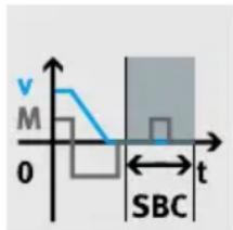
The function described here implements the safety sub-function SBC according to EN 61800-5-2.
The safety sub-function SBC is used for controlling a holding brake in the motor and a clamping unit or brake on the axis to slow an axis down mechanically or stop it safely.
Function and application of SBC
The safety sub-function SBC provides safe output signals for the control of brakes (holding brakes or clamping units). The brakes are controlled on 2 channels by switching off the voltage at the following outputs:
- Safe output BR+/BR-[X6B] for the holding brake of the motor
- Safe output BR-EXT/GND [X1C] for the external brake/clamping unit
The holding brake and/or clamping unit engage and slow the motor or axis. The purpose of this is to slow down dangerous movements by mechanical means. The braking time is dependent on how quickly the brake engages and how high the energy level is in the system.
The use of just one brake is only possible when performance requirements are low Tab. 18 Safety reference data for the safety sub-function SBC. To do this, connect the brake either to BR+/BR- or to BR-EXT.
NOTICE
If there are suspended loads, they usually drop if SBC is requested simultaneously with STO. This can be traced back to the mechanical inertia of the holding brake or clamping unit and is thus unavoidable. Check whether safety sub-function SS1 is better suited to your application.
SBC may only be used for holding brakes or clamping units which engage in the de-energised state. Ensure the lines are protected when installed.
Functional principle of SBC
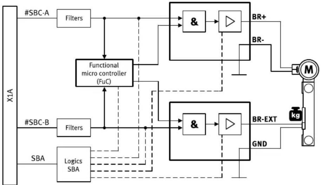
flowchart
graph TD
    A["X1A"] --> B["#SBC-A"]
    B --> C["Filters"]
    C --> D["Functional micro controller (FuC)"]
    D --> E["&"]
    E --> F["Δ"]
    F --> G["BR+"]
    F --> H["BR-"]
    D --> I["&"]
    I --> J["Δ"]
    J --> K["BR-EXT"]
    K --> L["kg"]
    L --> M["GND"]
    M --> N["SBA"]
    N --> O["Logics SBA"]
    O --> P["Filters"]
    P --> Q["Functional micro controller (FuC)"]
    Q --> R["&"]
    R --> S["Δ"]
    S --> T["BR-EXT"]
    T --> U["GND"]
    U --> V["M"]
    V --> W["Feedback to #SBC-A"]
Fig. 4: Functional principle of SBC
SBC request
The safety sub-function SBC is requested on 2 channels by simultaneously switching off the control voltage at both control inputs #SBC-A and #SBC-B:
- The #SBC-A request switches off the power to the signals BR+/BR-.
- The #SBC-B request switches off the power to the signal BR-EXT.
In the event of a power failure in the logic voltage supply of the servo drive, power is also cut off to the brake outputs.
i
If SBC is requested and subsequently cancelled, the safe brake control is only re-energised when the functional micro controller enables the holding brake. This ensures that Z-axes with a suspended load can be restarted without the load dropping.
SBC feedback via SBA diagnostic contact
The 2-channel switching of the brake is indicated via the SBA output. SBA is used to report the status of the safety sub-function SBC for diagnostic purposes, e.g. by reporting it to an external safety relay unit.
The SBA diagnostic output indicates whether the safe status has been reached for the safety sub-function SBC. It is set if the following two conditions are fulfilled:
-Switching off of both brake outputs is requested (#SBC-A = #SBC-B = low level)
- The internal diagnostic functions have determined that there is no internal error and both brake outputs are de-energised (switched off).
Test pulses that occur simultaneously at SBC-A and SBC-B are not filtered. For this reason, the SBA diagnostic output delivers a high level signal for the duration of these low test pulses.
Testing the safety sub-function SBC
Test inputs #SBC-A and #SBC-B separately from each other and together. The diagnostic feedback may only be set to high level when inputs #SBC-A and #SBC-B are both requested. If the signal behaviour does not correspond to expectations, the system must be set to a safe condition within the reaction time. It is essential that time monitoring be provided in the safety relay unit.
The safety sub-function SBC with feedback via SBA must be tested at least 1x within the space of 24 h.
- Test SBA feedback based on the SBC-A and SBC-B level according to the following table.
| #SBC-A (BR+) #SBC-B (BR-Ext) SBA | |
| Low level Low level High level | |
| Low level High level Low level | |
| High level Low level Low level | |
| High level High level Low level |
Tab. 5: Testing all SBC levels
While you are testing the safety sub-function SBC, discrepancy error detection may be activated in the CMMT-AS if the test lasts longer than 200 ms. If a corresponding error message is output by the basic unit, you will need to acknowledge it.
Evaluation of SBA
Recommendation: evaluation with every actuation.
- Check SBA feedback whenever there is a request.
| #SBC-A (BR+) #SBC-B (BR-Ext) SBA | |
| Low level Low level High level | |
| High level High level Low level |
Tab. 6: Evaluation of SBC level
Timing SBC
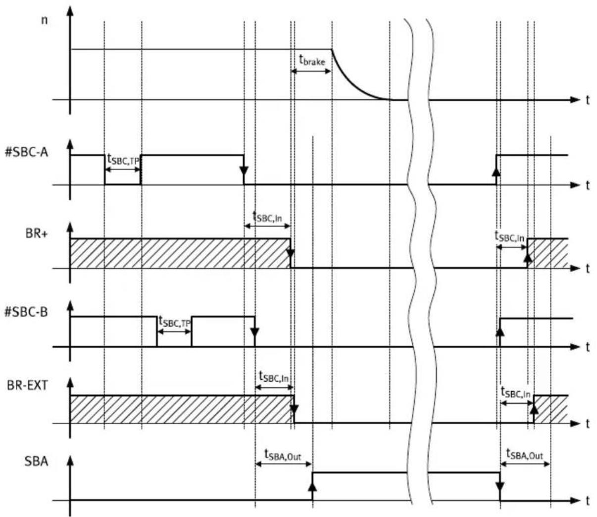
other
| Channel | Signal Type | Duration (s) | |---------|-------------|--------------| | #SBC-A | sSBC,TP | t_SBC,TP | | BR+ | sSBC,In | t_SBC,In | | #SBC-B | sSBC,TP | t_SBC,TP | | BR-EXT | sSBC,In | t_SBC,In | | SBA | sSBA,Out | t_SBA,Out |Fig. 5: SBC timing diagram
Legend for SBC timing
| Term/abbreviation Explanation | |
| t_Brake | Mechanical delay of the brake |
| #SBC-A/#SBC-B 2-channel input for SBC request | |
| t_SBC,TP | Length of low test pulses^1) at #SBC-A/B |
| t_SBC,In | Max. delay until the related brake output is switched off (≤ permissible reaction time when a safety sub-function is requested1) |
| SBA Feedback, SBC active | |
| t_SBA,Out | Max. delay for diagnostic feedback (≤ permissible reaction time when a safety sub-function is requested1) + 10 ms) |
| n Rotational speed | |
1) see Technical data, safety reference data SBC
Tab. 7: Legend for SBC timing
Requirements for the brakes
- Check the brakes used for suitability for the application.
As a rule, the brakes used are holding brakes. This means the brakes are well suited to keeping the motor at a standstill.
The internal holding brake of the motor is also used for the safety sub-function SBC. Please be aware of the following constraints:
- The holding brake must be designed for the load torque that is to be held.
–The specifications for the holding brakes permit a certain amount of movement until the full holding torque is reached. This must be taken into account in the design of the vertical axes and configuration of the safety sub-function SBC.
- “Reserves” should be factored in when selecting the motor plus holding brake, e.g. operation at no more than 2/3 of the nominal torque. The holding brakes in the motors are usually designed so that the motor shaft will come to a standstill without coasting at loads below 70% of the nominal torque.
- Depending on the hazard situation, the holding brake must be designed with a correspondingly higher nominal torque.
- When designing the holding brake, the additional load torque for the brake test must be considered.
The number of clamping and braking applications for the clamping unit is limited by its wear.
-
Observe the corresponding information in the datasheet.
-
Replace clamping unit before the maximum number of clamping applications is reached.
-
Replace clamping unit if the emergency brake features of the clamping unit have to be used. Note the permissible number of emergency braking applications.
Brake test
- Check whether a brake test is required. The DGUV information sheet “Gravity-loaded axis” provides information on this.
4.1.4 Safety sub-function SS1
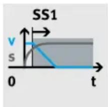
The function described here implements the safety sub-function SS1-t according to EN 61800-5-2.
Product overview
The safety sub-function SS1 is used when the motor needs to be braked and the power supply to the motor then has to be safely switched off in the application but there are no further requirements for a targeted standstill of the drive (controlled stop, stop category 1 according to EN 60204-1).
Together with a suitable safety relay unit, the following can be achieved:
- Safe stop 1 time controlled (SS1-t/Safe stop 1 time controlled); triggering of motor deceleration and, after an application-specific time delay, triggering of the safety sub-function STO
Requirements of SS1
-For details of wiring the safety sub-function STO, see Fig. 10.
- Execute emergency stop command with the safety relay unit (either directly by wiring CTRL-EN accordingly or indirectly via a further functional controller).
–The time for executing an emergency stop is known.
- The safety relay unit supports programmable timers and simple logic elements.
Function and application of SS1
The procedure for triggering SS1-t comprises the following steps:
- Functional emergency stop requested (e.g. set input CTRL-EN to low level).
This causes the servo drive to trigger a braking ramp function and – if present – allows the brake function to engage at the end of the braking ramp. On completion of the braking ramp and once the parameterisable delay time for brake closing has elapsed, the power stage is functionally switched off.
- Start of a time-delay element for actuation of STO.
Select a delay time that ensures the functional braking ramp is completed in normal operation, the holding brake function is engaged and the power stage is functionally switched off. Otherwise, the axis may drop if STO is triggered concurrently with the brake engagement time that is required for mechanical reasons. If the brake is engaged while the axis is still in motion, increased wear will occur on the holding brake (only permitted for emergency braking).
- Safety sub-function STO requested plus – if required – SBC once the delay time has elapsed.
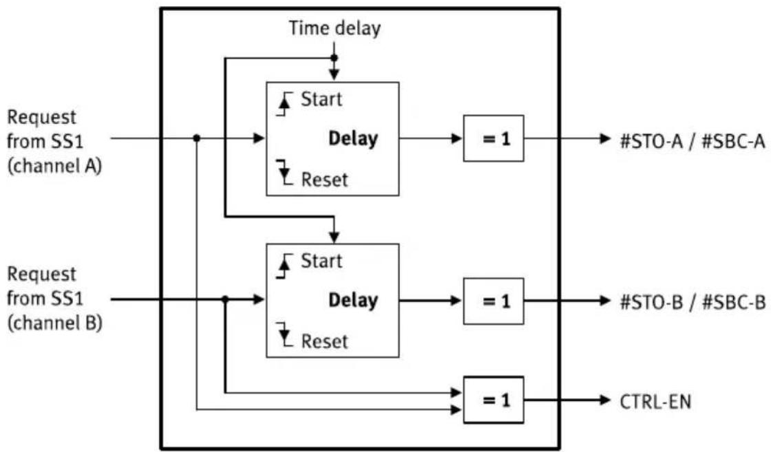
The figure below shows the necessary logic circuits for the safety relay unit:
Logic in the safety relay unit for SS1
flowchart
graph TD
    A["Request from SS1 (channel A)"] --> B["Start"]
    B --> C["Delay"]
    C --> D["= 1"] --> E["#STO-A / #SBC-A"]
    F["Request from SS1 (channel B)"] --> G["Start"]
    G --> H["Delay"]
    H --> I["= 1"] --> J["#STO-B / #SBC-B"]
    K["Time delay"] --> C
    K --> G
    L["Reset"] --> G
    M["Reset"] --> H
    N["= 1"] --> O["CTRL-EN"]
Fig. 6: Logic in the safety relay unit for SS1
T
The delay times are directly included in the reaction time of the system.
SS1 feedback
The STA signal can be used as feedback for the safety sub-function SS1.
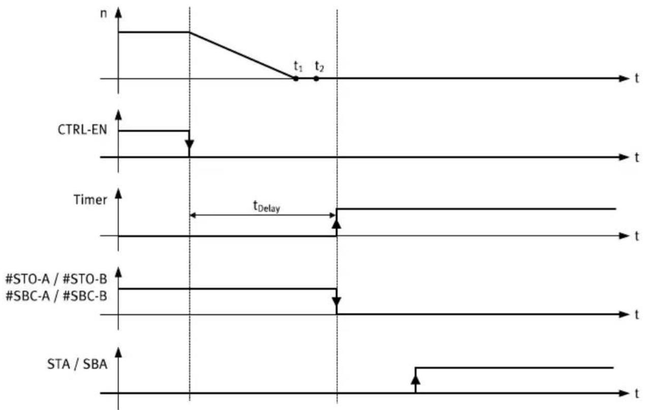
Timing of SS1
flowchart
graph TD
    A["Start"] --> B{n}
    B --> C["t1"]
    C --> D["t2"]
    E["CTRL-EN"] --> F["t"]
    F --> G["t"]
    H["Timer"] --> I["t"]
    I --> J["t"]
    K["#STO-A / #STO-B"] --> L["t"]
    M["#SBC-A / #SBC-B"] --> N["t"]
    O["STA / SBA"] --> P["t"]
    Q["tDelay"] --> R["t"]
    style A fill:#f9f,stroke:#333
    style E fill:#f9f,stroke:#333
    style H fill:#f9f,stroke:#333
    style K fill:#f9f,stroke:#333
    style M fill:#f9f,stroke:#333
    style O fill:#f9f,stroke:#333
Fig. 7: Timing diagram SS1
Legend for SS1 timing
| Term/abbreviation Explanation | |
| Timer Delay element in safety relay unit | |
| CTRL-EN Enable signal | |
| t_Delay | Delay time until STO and SBC are requested (drive has safely come to a standstill and brake is closed) |
| #STO-A/B 2-channel input for STO request | |
| #SBC-A/B 2-channel input for SBC request | |
| STA Feedback, STO active | |
| SBA Feedback, SBC active | |
| t_1 | Braking ramp followed, rotational speed = 0 (functionally) |
| t_2 | Brake closed and power stage switched off (functionally) |
| n Rotational speed | |
Tab. 8: Legend for SS1 timing
SBC request
i
If there are suspended loads, they usually drop if STO and SBC are requested directly before the braking ramp is completed because the engagement time of the holding brakes must be considered. For details of how to wire up safety sub-function STO with SBC, see Fig. 11.
- When selecting the delay time t_Delay , make sure it is long enough to account for the maximum braking ramp time and brake engagement time.
4.1.5 Cross wiring of several servo drives
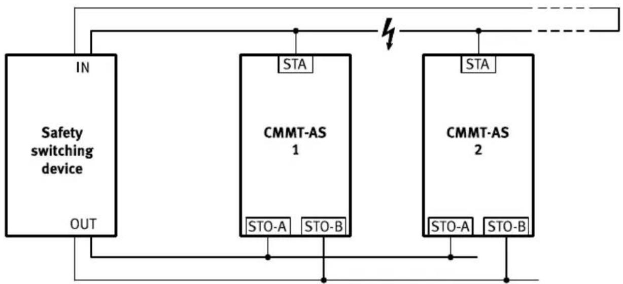
For cross wiring, wire the diagnostic outputs as a ring. Route both ends of the ring to a 2-channel input of the safety relay unit. The safety relay unit monitors for discrepancies. A maximum of 10 servo drives can be wired in parallel.
Cross-wiring, example STA
flowchart
graph TD
    A["Safety switching device"] -->|IN| B["STA"]
    A -->|OUT| C["STO-A"]
    A -->|OUT| D["STO-B"]
    E["CMMT-AS 1"] --> F["STA"]
    G["CMMT-AS 2"] --> H["STA"]
    I["Power Supply"] --> J["Output"]
Fig. 8: Cross-wiring, example STA
For cross-wired diagnostic outputs, the condensed state results from a logical AND link. An output of a CMMT-AS is capable of pulling all other outputs to low signal. A high signal is present at the two inputs of the safety relay unit only if all diagnostic outputs deliver high signals. The ring-shaped cross wiring of the diagnostic outputs with sensing at the beginning and end of the signal chain makes it possible to detect cable breaks in the cross wiring.
At this point, the diagnostic outputs deviate from the closed current principle. Cyclical automatic testing of the diagnostic output by the safety relay unit is therefore highly recommended → STO feedback via STA diagnostic contact and → SBC feedback via SBA diagnostic contact.
Put suitable measures in place to prevent faulty wiring:
Product overview
- Exclude wiring faults in accordance with EN 61800-5-2
- Configure the safety relay unit to monitor the outputs of the safety relay unit and wiring up to the servo drive
4.1.7 Safety relay unit
Use suitable safety relay units with the following characteristics:
- 2-channel outputs with
– Detection of shorts across contacts
- Required output current (also for STO)
- Low test pulses up to a maximum length of 1 ms
-Evaluation of the diagnostic outputs of the servo drive
Safety relay units with high test impulses can be used with the following restrictions:
- Test impulses up to 1 ms in length
- Test impulses are not simultaneous/overlapping on #STO-A/B and #SBC-A/B
- The resulting safety-related classification depends on the evaluation of diagnostic feedbacks STA, SBA 9.1 Technical data, safety engineering, safety reference data STO and SBC.
The safety relay units Pilz PNOZmulti, Pilz PNOZmulti Mini or SIEMENS ET 200SP with PP-switching output modules, for example, would be suitable.
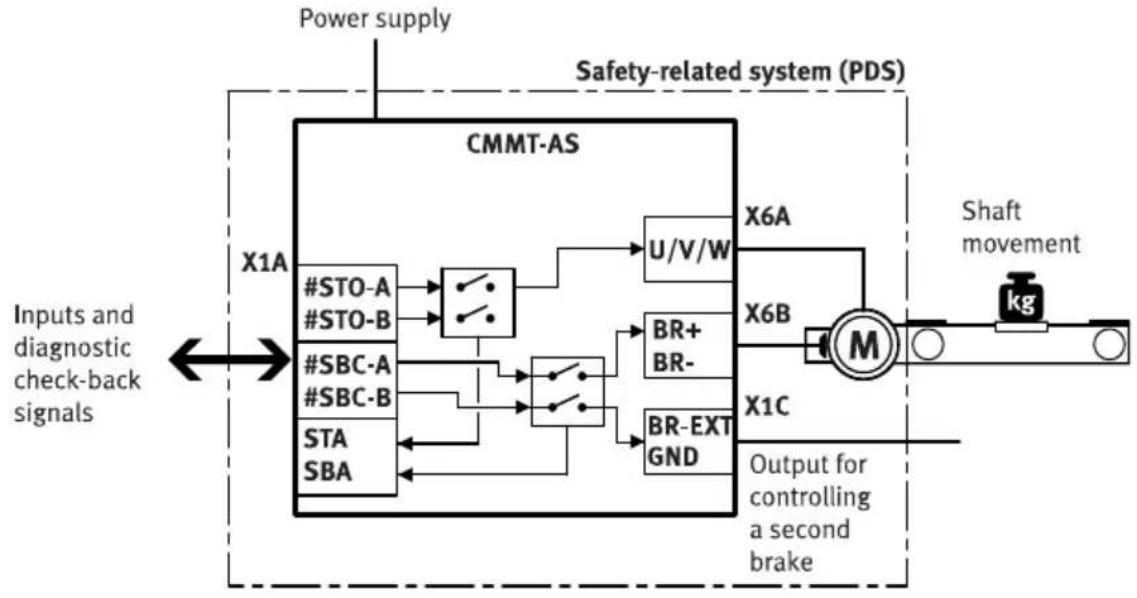
4.1.8 Interfaces of the PDS
The interfaces of the PDS(SR) (Power Drive System, safety related) to the outside world are:
-Power supply
- Inputs and diagnostic feedback signals
- Movement of the shaft
-Output for controlling a second brake
flowchart
graph LR
    A["Inputs and diagnostic check-back signals"] --> B["CMMT-AS"]
    B --> C["X1A"]
    B --> D["X6A"]
    B --> E["X1C"]
    C --> F["#STO-A"]
    C --> G["#STO-B"]
    D --> H["#SBC-A"]
    D --> I["#SBC-B"]
    E --> J["STA SBA"]
    F --> K["Switch"]
    G --> L["Switch"]
    H --> M["Switch"]
    I --> N["Switch"]
    K --> O["U/V/W"]
    L --> P["BR+ BR-"]
    M --> Q["BR-EXT GND"]
    N --> R["Output for controlling a second brake"]
    O --> S["M"]
    P --> S
    Q --> S
    R --> T["Shaft movement"]
    S --> U["kg"]
    V["Power supply"] --> W["Safety-related system (PDS)"]
Fig. 9: Interfaces of the PDS
5 Installation
5.1 Safety

WARNING
Risk of injury due to electric shock.
- For the electrical power supply with extra-low voltages, use only PELV circuits that guarantee a reinforced isolation from the mains network.
- Observe IEC 60204-1/EN 60204-1.
i
Comprehensive information concerning the electrical installation of the device 1.2 Applicable documents, Manual Assembly, Installation.
Information for operation with safety function
NOTICE
Check the safety functions to conclude the installation process and after every modification to the installation.
During installation of safety-related inputs and outputs, also observe the following:
-Comply with all specified requirements, e.g.:
-Surrounding area (EMC)
- Logic and load voltage supply
- Mating plug
-Connecting cables
-Cross-wiring
- Additional information → Manual Assembly, Installation.
- The maximum permissible cable length between the safety relay unit and the plug connector of the I/O interface is 3 m.
- Comply with the requirements of EN 60204-1 for the installation. In the event of a fault, the voltage must not exceed 60 V DC. The safety relay unit must switch off its outputs in the event of a fault.
- Install wiring between the safety relay unit and the I/O interface of the servo drive in such a way as to eliminate the risk of a short circuit between the conductors or to 24 V, as well as a cross circuit EN 61800-5-2, Annex D.3.1. Otherwise, the safety relay unit must feature detection of shorts across contacts and, in the event of a fault, must switch off the control signals on 2 channels.
- Use only suitable mating plugs and connecting cables Manual Assembly, Installation.
- Prevent conductive contamination between neighbouring plug pins.
- Ensure that no bridges or similar can be used parallel to the safety wiring, e.g. by using the maximum wire cross-section or suitable plastic wire end sleeves.
- Use twin ferrules for cross-wiring of safety-relevant inputs and outputs. A maximum of 10 devices may be cross-wired when cross-wiring inputs and outputs Manual Assembly, Installation.
- The safety relay unit and its inputs and outputs must meet the necessary safety classification of the safety function that is required for the specific case.
- Connect each of the control inputs to the safety relay unit on 2 channels using parallel wiring.
Installation
- Only use permitted motor cables for the BR+/BR- connection.
- If the diagnostic output of the safety sub-function concerned has to be evaluated: connect diagnostic output directly to the safety relay unit. Evaluation of the diagnostic output is either mandatory or optional depending on which safety classification is desired.
- If diagnostic outputs are cross-wired for a device compound: wire diagnostic outputs as a ring. Run the two ends of the ring to the safety relay unit and monitor for discrepancies.
Basic circuitry design
- Safe sensors, e.g. emergency stop switches, light curtains, are routed to the safety relay unit (or the safety PLC).
- The safety relay unit requests the safety sub-functions on the servo drive via 2 channels and evaluates the related feedback signals.
- Connecting sensors, e.g. emergency stop switches, directly to the servo drive is not permitted, because this means that the sensors are not monitored.
5.2 STO installation
Inputs and outputs for the safety sub-function STO
The 2-channel request for the safety sub-function is made via the digital inputs #STO-A and #STO-B. The STA diagnostic output indicates whether the safe status has been reached for the safety sub-function STO.
| Connection Pin Type Identifier Function | ||||
| [X1A] X1A.11 | DIN #STO- | B Safe torque off, channel B | ||
| X1A.12 #STO-A Safe torque off, channel A | ||||
| X1A.22 DOUT STA Safe torque off acknowledge | ||||
Tab. 9: Inputs and outputs for the safety sub-function STO
STO connection example
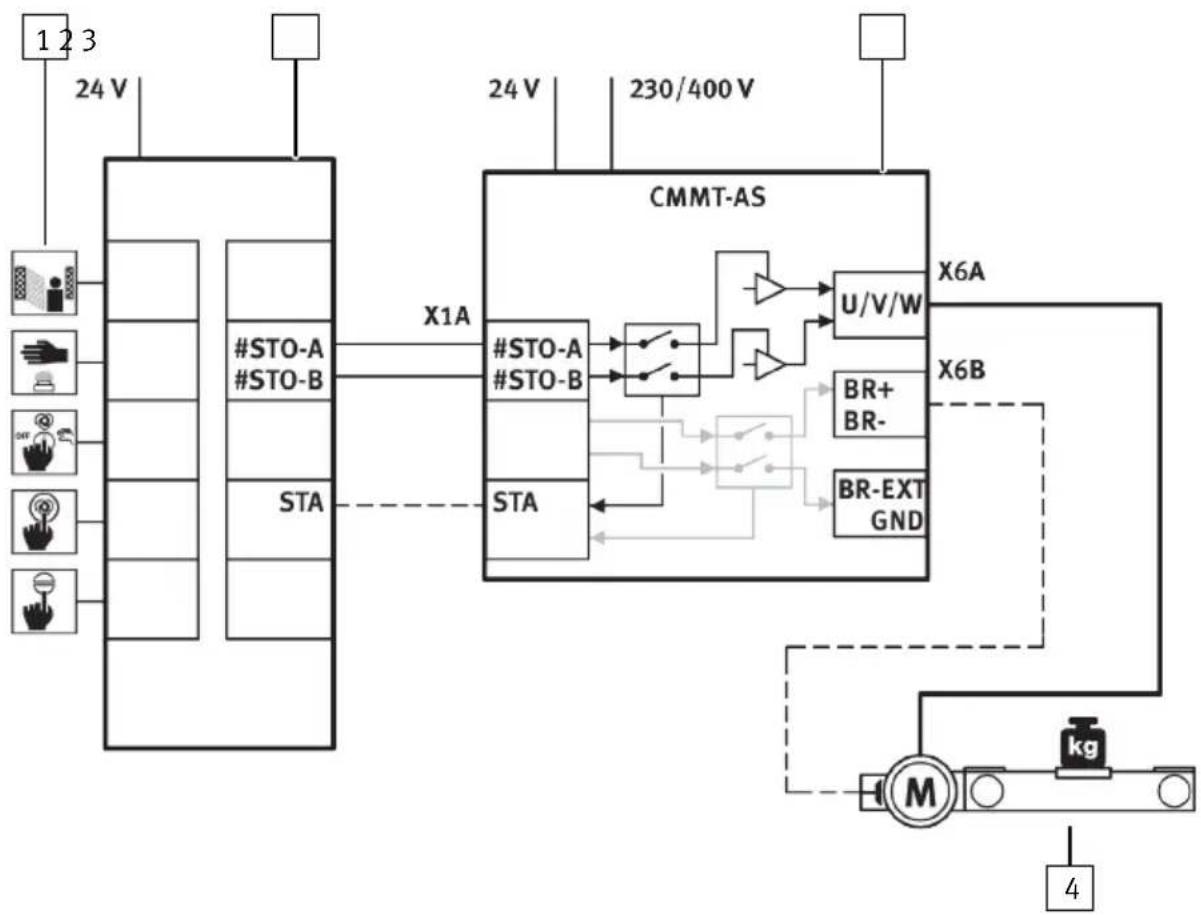
The safety sub-function STO (safe torque off) is triggered by an input device that makes the safety request (e.g. light curtain).
Installation
flowchart
graph TD
    A["1 2 3"] --> B["#STO-A"]
    A --> C["#STO-B"]
    A --> D["STA"]
    B --> E["X1A"]
    C --> E
    D --> E
    E --> F["#STO-A"]
    E --> G["#STO-B"]
    F --> H["BR+ BR-"]
    G --> I["BR-EXT GND"]
    H --> J["U/V/W"]
    I --> J
    J --> K["X6A"]
    J --> L["X6B"]
    M["M"] --> N["kg"]
    N --> O["4"]
Fig. 10: STO sample circuit
1 Input device for safety request, e.g. light curtain
3 Servo drive CMMT-AS
2 Safety relay unit
4 Drive axis
Information on the sample circuit
The safety request is passed on to the servo drive on 2 channels via the #STO-A and #STO-B inputs at the connection [X1A]. This safety request results in the 2-channel switch-off of the driver power supply to the servo drive's power output stage. The safety relay unit can use the STA diagnostic output to monitor whether the safe status has been reached for the safety sub-function STO.
5.3 SBC installation
Inputs and outputs for the safety sub-function SBC
The 2-channel request for the safety sub-function is made via the digital inputs #SBC-A and #SBC-B at the connection [X1A]. The SBA diagnostic output indicates whether the safe status has been reached for the safety sub-function SBC. The holding brake is connected via the connection [X6B]. The external clamping unit is connected via the connection [X1C].
| Connection Pin Type Identifier Function | ||||
| [X1A] X1A.9 | DIN #SBC-B | Safe brake | control, channel B | |
| X1A.10 #$BC-A Safe | brake control, channel A | |||
| [X1A] X1A.21 | DOUT SBA Safe brake control acknowledge | |||
| [X1C] X1C.1 | DOUT BR-EXT Output for connection of an external clamping unit (High-Side-Switch) | |||
| X1C.5 GND Reference potential | ||||
| [X6B] X6B.1 | FE Functional earth connected to protective earth | |||
| X6B.2 OUT BR+ Holding brake (positive potential) | ||||
| X6B.3 | BR- | Holding brake (negative potential) | ||
Tab. 10: Inputs and outputs for the SBC safety sub-function
SBC connection example
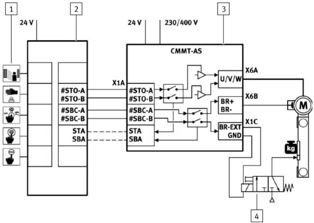
The safety sub-function SBC (safe brake control) is triggered by an input device that makes the safety request.
flowchart
graph TD
    A["1"] --> B["24 V"]
    B --> C["#STO-A"]
    B --> D["#STO-B"]
    B --> E["#SBC-A"]
    B --> F["#SBC-B"]
    B --> G["STA SBA"]
    C --> H["X1A"]
    D --> H
    E --> H
    F --> H
    G --> H
    H --> I["#STO-A"]
    H --> J["#STO-B"]
    H --> K["#SBC-A"]
    H --> L["#SBC-B"]
    H --> M["STA SBA"]
    I --> N["BR+ BR-"]
    J --> N
    K --> N
    L --> N
    M --> N
    N --> O["U/V/W"]
    O --> P["X6A"]
    N --> Q["X6B"]
    Q --> R["X1C"]
    R --> S["MR"]
    S --> T["kg"]
    T --> U["4"]
Fig. 11: SBC sample circuit
1 Input device for safety request, e.g. light curtain
2 Safety relay unit
3 Servo drive CMMT-AS
4 Control (in this example: solenoid valve) of the clamping unit
Information on the sample circuit
Installation
The safety request is passed on to the servo drive on 2 channels via the inputs #SBC-A and #SBC-B at the connection [X1A].
- The request via the input #SBC-A switches off power to the signals BR+ and BR- at the connection [X6B]. This de-energises and closes the holding brake.
- The request via the input #SBC-B switches off power to the signal BR-EXT at the connection [X1C]. This shuts off power to the control of the external clamping unit. The clamping unit closes.
- The safety relay unit monitors the SBA diagnostic output and checks whether the safe status has been reached for the safety sub-function SBC.
5.4 SS1 installation
Inputs and outputs for the safety sub-function SS1
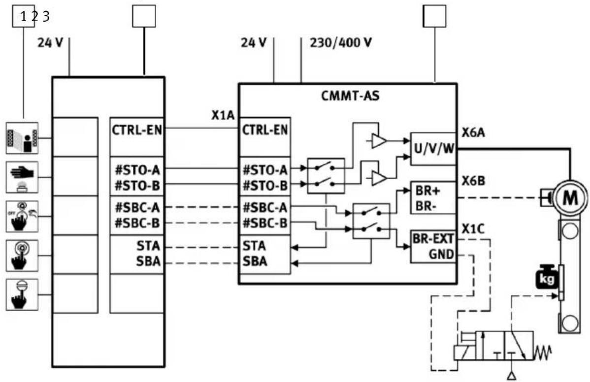
The safety sub-function SS1 is wired like the safety sub-function STO but is supplemented by the functional input CTRL-EN so that the braking ramp can be activated by the safety relay unit.
SS1 connection example
flowchart
graph TD
    A["1 2 3"] --> B["24 V"]
    B --> C["CTRL-EN"]
    C --> D["X1A"]
    D --> E["CMMT-AS"]
    E --> F["U/V/W"]
    F --> G["X6A"]
    E --> H["X6B"]
    H --> I["M"]
    I --> J["kg"]
    J --> K["Output"]
    style A fill:#f9f,stroke:#333
    style B fill:#ccf,stroke:#333
    style C fill:#cfc,stroke:#333
    style D fill:#fcc,stroke:#333
    style E fill:#cff,stroke:#333
    style F fill:#ffc,stroke:#333
    style G fill:#fcc,stroke:#333
    style H fill:#ffc,stroke:#333
    style I fill:#fcc,stroke:#333
    style J fill:#fcc,stroke:#333
    style K fill:#fcc,stroke:#333
Fig. 12: SS1 sample circuit
1 Input device for safety request
2 Safety relay unit
3 Servo drive CMMT-AS
5.5 Installation for operation without safety sub-function
Minimum wiring for operation without safety sub-function
For operation without the safety sub-function, wire inputs X1A.9 to X1A.12 as follows:
| Connection Pin Type Identifier Function | ||||
| [X1A] X1A.9 | DIN #SBC-B Supplies | each one with 24 V | ||
| X1A.10 #BC-A | ||||
| X1A.11 #TO-B | ||||
| X1A.12 #$TO-A | ||||
| X1A.21 DOUT SBA Do not connect | ||||
| X1A.22 STA | ||||
Tab. 11: Wiring of inputs and outputs without safety sub-function
6 Commissioning
6.1 Safety
Use of the safety functions
NOTICE
The safety sub-functions STO and SBC are already available on the CMMT-AS on delivery without the need for any additional parameterisation. Prior to initial commissioning, you must – as a minimum – wire safety sub-functions STO and SBC.
- Make sure that each safety function of the system is analysed and validated. It is the responsibility of the operator to determine and verify the required safety classification (safety integrity level, performance level and category) of the system.
- Put the servo drive into operation and validate its behaviour in a test run.
During integration of the PDS, observe the measures stipulated by standard EN ISO 13849-1, Chapter G.4: - Functional test
- Project management
- Documentation
- Performance of a black-box test
6.2 Check lists
The safety functions must be validated after installation and after every modification to the installation. This validation must be documented by the person who commissions the device. To assist you with commissioning, we have put together some sample questions for risk reduction in the form of the check lists below.
i
The following check lists are no substitute for safety training. No guarantee can be provided for the completeness of the check lists.
| No. | Questions Relevant Done | ||
| 1. Have | all operating conditions and all means of intervention (possibility of intervening in the operation of the machine, but also physical intervention in the machine) been taken into account? | yes □no □ | □ |
| 2. Has | the 3-step method for risk reduction been applied, i.e.: 1. Inherently safe design, 2. Technical and possibly additional protective measures, 3. User information about the residual risk? | yes □no □ | □ |
| 3. Have | the hazards been eliminated or the hazard risks reduced as far as practically possible? | yes □no □ | □ |
| 4. Can | it be guaranteed that the implemented measures do not create new hazards? | yes □no □ | □ |
| 5. Have | the end users been given sufficient information and warning regarding the residual risks? | yes □no □ | □ |
| 6. Can | it be guaranteed that the implemented protective measures have not led to a deterioration in the working conditions of the operating personnel? | yes □no □ | □ |
| 7. Are | the implemented protective measures mutually compatible? yes □ | no □ | □ |
| 8. Has | adequate consideration been given to the potential consequences of using a machine designed for commercial/industrial purposes in a non-commercial/non-industrial area? | yes □no □ | □ |
| 9. Can | it be guaranteed that the implemented measures will not severely impair the machine's ability to perform its function? | yes □no □ | □ |
Tab. 12: Questions for validation in accordance with EN 12100 (example)
| No. Questions Relevant Done | |||
| 1. Has | a risk assessment been carried out? yes □ | no □ | □ |
| 2. Have | a list of issues and a validation plan been drawn up? yes □ | no □ | □ |
| 3. Has | the validation plan – including analysis and inspection – been worked through and has a validation report been created? The following must be inspected as a minimum as part of the validation: | yes □ no □ | □ |
| ... a) | Inspection of components: is the CMMT-AS-...-S1 being used (check using the rating plate)? | yes □ no □ | □ |
| ... b)No. | Is the wiring correct (check using the circuit diagram)? yes □Questions Relevant Done | no □ | □ |
| ... b1) | Have the inputs for STO and SBC been wired to the safety relay unit via 2 channels? | yes □no □ | □ |
| ... b2) | Have the check-back outputs STA, SBA been wired to the safety relay unit? | yes □no □ | □ |
| ... b3) | If multiple CMMT-AS have been connected together (linked) via X1A: have the connection instructions been taken into account?→ 4.1.5 Cross wiring of several servo drives. | yes □no □ | □ |
| ... c) F | Functional tests: yes □ | no □ | □ |
| ... c1) | Actuation of the system emergency stop: is the drive brought to a standstill in the desired manner (stop 0, stop 1, SBC)? | yes □no □ | □ |
| ... c2) | Is a restart after an emergency stop prevented in the safety relay unit? This means that when the emergency stop button is pressed and the enable signals are active, no movement occurs in response to a start command until acknowledgement has taken place via the “Restart” input. | yes □no □ | □ |
| ... c3) | Actuation of the safety sub-function STO. If only one of the assigned inputs #STO-A or #STO-B is activated: is the safety sub-function STO executed immediately? Does the STA output remain at the low level? Is the error “Discrepancy time violation” logged in the CMMT-AS once the discrepancy time has elapsed? | yes □no □ | □ |
| ... c4) | Actuation of the safety sub-function SBC. If only one of the assigned inputs #SBC-A or #SBC-B is activated: is the assigned safety sub-function executed immediately? Does the SBA output remain at the low level? Is the error “Discrepancy time violation” logged in the CMMT-AS once the discrepancy time has elapsed? | yes □no □ | □ |
| ... c5) | Does the safety relay unit detect a fault if SBA/STA do not switch to the high level when the safety sub-function is requested via 1 channel? | yes □no □ | □ |
| ... c6) | Only when linking multiple CMMT-AS and connecting the diagnostic outputs: does the safety relay unit detect a fault if the SBA/STA linkage is interrupted at a particular point and the corresponding diagnostic output does not switch to the high level on one CMMT-AS when the safety sub-function is requested via single-channel? | yes □no □ | □ |
Tab. 13: Questions for validation in accordance with EN ISO 13849-2 (example)
7 Operation
Check the safety functions at adequate intervals for proper functioning. It is the responsibility of the operator to choose the type and frequency of the checks within the specified time period. The manner in which the test is conducted must make it possible to verify that the safety device is functioning perfectly in interaction with all components. Time period for cyclical test 9.1 Technical data, safety engineering.
The CMMT-AS is maintenance-free during its period of use and specified service life. The test interval varies from one safety sub-function to another:
- STO: no test has to be carried out during the period of use, but we recommend evaluating STA whenever the sub-function is requested to ensure maximum diagnostic coverage and the highest safety-related classification.
- SBC: cyclical test required at least once every 24 h and SBA evaluation recommended whenever the sub-function SBC is requested to ensure maximum diagnostic coverage and the highest safety-related classification.
8 Malfunctions
8.1 Diagnostics via LED
Safety LED, status of the safety engineering
Malfunctions of the safety sub-functions are detected and displayed in the functional device. The following are detected:
–Safety sub-functions requested via 1 channel (discrepancy monitoring)
- Internal device errors that lead to pulse monitoring not being switched off or only switched off on one channel
- Errors in the brake outputs or the external wiring that result in voltage being present on the brake output even though the safety sub-function SBC has been requested
Malfunctions are externally reported by the functional part, including via the additional communication interfaces (bus, commissioning software).
| LED Meaning | ||
 | flashing red | Error in the safety part or a safety condition has been violated. |
 | flashing yellow | The safety sub-function has been requested but is not yet active. |
 | yellow light | The safety sub-function has been requested and is active. |
 | flashing green | Power stage, brake outputs and safety diagnostic outputs are blocked (safety parameterisation is running). |
 | green light | Ready, no safety sub-function has been requested. |
Tab. 14: Safety LED
8.2 Repair
Repair or maintenance of the product is not permissible. If necessary, replace the complete product.
- If there is an internal defect: Always replace the product.
- Send the defective product unchanged, together with a description of the error and application, back to Festo.
- Check with your regional Festo contact person to clarify the conditions for the return shipment.
9 Technical data
9.1 Technical data, safety engineering
Approval information, safety engineering
| CE | |
| Type-examination The functional safety engineering of the product has been certified by an independent testing body, see EC-type examination certificate → www.festo.com/sp | |
| Certificate issuing authority TÜV Rheinland, Certification Body of Machinery, NB 0035 | |
| Certificate no. 01/205/5640.01/23 | |
| UKCA | |
| Type-examination The functional safety engineering of the product has been certified by an independent body, see UK-type examination certificate → www.festo.com/sp | |
| Certificate issuing authority TÜV Rheinland UK Ltd, Approved Body for Machinery, No. 2571 | |
| Certificate no. 01/205U/5640.01/23 |
Tab. 15: Approval information, safety engineering
General safety reference data
| Request rate in accordance with EN 61508 | High request rate |
| Reaction time when the safety sub-function is requested | [ms] < 10 (applies to STO and SBC) |
| Error reaction time (how long it takes for the diagnostic output status to become correct once the safety sub-function has been requested) | [ms] < 20 (applies for STA and SBA) |
Tab. 16: Safety reference data and safety specifications
| Safety reference data for the safety sub-function STO | |||
| Circuitry without hightest | pulses, without or with STA evaluation | with hightest pulses and with STA evaluation^1) | with hightest pulses and without STA evaluation |
| Safety sub-function in accordance with EN 61800-5-2 | Safe torque off (STO) | ||
| Safety integrity level in accordance with EN 61508 | SIL 3 SIL 3 SIL 2 | ||
| Category in accordance with EN ISO 13849-1 | Cat. 4 Cat. 4 Cat. 3 | ||
| Performance level in accordance with EN ISO 13849-1 | PL e PL e PL d | ||
| Probability of dangerous failure per hour in accordance with EN 61508, PFH | [1/h] 3.70 x 10 ^-11 | 9.40 × 10^-11 | 5.90 × 10^-10 |
| Mean time to dangerous failure in accordance with EN ISO 13849-1, MTTFd | [a] 2400 1960 1960 | ||
| Average diagnostic coverage in accordance with EN ISO 13849-1, DC _AVG | [%] 97 95 75 | ||
| Operating life (mission time) in accordance with EN ISO 13849-1, TM | [a] 20 | ||
Safety reference data for the safety sub-function STO
| Circuitry without hightest | pulses, without or with STA evaluation | with hightest pulses and with STA evaluation^1) | with hightest pulses and without STA evaluation |
| Safe failure fraction SFF in accordance with EN 61508 [%] 99 99 99 | |||
| Hardware fault tolerance in accordance with EN 61508, HFT | 1 | ||
| Common cause factor for dangerous undetected failures β in accordance with EN 61508 [%] 5 | |||
| Classification in accordance with EN 61508 | Type A | ||
1) Safety sub-function STO tested and STA diagnostic output monitored by the safety controller at least once every 24 h.
Tab. 17: Safety reference data for the safety sub-function STO
Safety reference data for the safety sub-function SBC
| Circuitry 2 brakes | 1) with SBA evaluation2) | 1 brake3) without SBA evaluation |
| Safety sub-function in accordance with EN 61800-5-2 | Safe brake control (SBC) | |
| Safety integrity level in accordance with EN 61508 | SIL 3 SIL 1 | |
| Category in accordance with EN ISO 13849-1 | Cat. 3 Cat. 1 | |
| Performance level in accordance with EN ISO 13849-1 | PL e PL c | |
| Probability of dangerous failure per hour in accordance with EN 61508, PFH | [1/h] 3.00 x 10⁻¹⁰ | 9.00 × 10^-8 |
| Mean time to dangerous failure in accordance with EN ISO 13849-1, MTTFd | [a] 1400 950 | |
Safety reference data for the safety sub-function SBC
| Circuitry 2 brakes | 1) with SBA evaluation2) | 1 brake3) without SBA evaluation |
| Average diagnostic coverage in accordance with EN ISO 13849-1, DCAVG [%] 93 – | ||
| Operating life (mission time) in accordance with EN ISO 13849-1, TM [a] 20 | ||
| Safe failure fraction SFF in accordance with EN 61508 [%] 99 87 | ||
| Hardware fault tolerance in accordance with EN 61508, HFT | 1 | 0 |
| Common cause factor for dangerous undetected failures β in accordance with EN 61508 [%] 5 | ||
| Classification in accordance with EN 61508 | Type A | |
1) Connection of a brake to BR+/BR- and a second brake to BR-EXT; 2-channel wiring and request via #SBC-A and #SBC-B.
2) Monitoring of the safety sub-function via the SBA diagnostic output by the safety controller at least once every 24 hours.
3) Brake connected either to BR+/BR- or to BR-EXT; single-channel request via the safety controller using #SBC-A and #SBC-B; both inputs must be bridged externally.
Tab. 18: Safety reference data for the safety sub-function SBC
Remarks
- Depending on the desired safety classification, evaluation of the SBA diagnostic output by the safety relay unit is either mandatory or optional.
- To achieve the safety classification Cat. 3, PL d, SIL 2 (or also Cat. 2, PL c/d) in conjunction with 2 brakes, evaluation of the SBA diagnostic output is mandatory.
- If you require an SBC function with a classification higher than Cat. 1, PL c, the diagnostic outputs must be checked regularly – at least 1 x once every 24 h – by having them tested automatically by the safety relay unit (→ EN ISO 13849-1, Annex G.2).
- The safety relay unit must request the safety sub-function at least once within 24 h and thereby monitor the SBA diagnostic output to achieve a diagnostic coverage of at least 60%. If the signal response does not correspond to expectations, the system must be put into a safe condition within the reaction time. It is essential that time monitoring be provided in the safety controller.
i
The technical data for the safety sub-function SS1 must be calculated individually according to the application. Use the specified safety reference data for STO and SBC for the calculation.
9.2 General technical data
General technical data
| Declaration of conformity | → www.festo.com/sp |
| Type ID code CMMT-AS | |
| Type of mounting Mounting plate, attached with screws | |
| Mounting position Vertical, mounted on closed surface, free convection with unhindered air flow from bottom to top | |
| Product weight → Manual Assembly, Installation. | |
Tab. 19: General technical data
Ambient conditions, transport
| Transport temperature [°C] -25 ... +70 | |
| Relative humidity [%] 5 ... 95 (non-condensing) | |
| Max. transportation duration [d] 30 | |
| Permissible altitude [m] 12000 (above sea level) for 12 h | |
| Vibration resistance | Vibration test and free fall in packaging in accordance with EN 61800-2 |
Tab. 20: Ambient conditions, transport
Ambient conditions, storage
| Storage temperature [°C] -25 ... +55 | |
| Relative humidity [%] 5 ... 95 (non-condensing) | |
| Permissible altitude [m] 3000 (above sea level) | |
Tab. 21: Ambient conditions, storage
Ambient conditions, operation
| Ambient temperature at nom- [°C] 0 ... +40inal power | |
| Ambient temperature with [°C] 0 ... +50derating(-3%/°C at 40°C ... 50°C) | |
| Temperature monitoring | Monitoring of:- Cooling element (power module)- Air in the deviceSwitch-off if temperature is too high or too low |
Ambient conditions, operation
| Relative humidity [%] 5 ... 90 (non-condensing), no corrosive media permitted near the device | |
| Permissible setup altitude [m] 0 ... 1000 above sea level at nominal power | |
| Permissible setup altitude [m] 0 ... 2000 above sea level with derating (-10%/1000 m at 1000 m ... 2000 m) | Operation above 2000 m is not permitted! |
| Degree of protection in accordance with EN 60529 | IP20 (with attached mating plug X9A and with intended mounting on closed backwall, otherwise IP10) |
| Requirements for installation space | Install in a control cabinet with at least IP54, design as “closed electrical operating area” in accordance with IEC 61800-5-1, Chap. 3.5 |
| Protection class I | |
| Overvoltage category III | |
| Pollution degree 2 (or better) | |
| Vibration resistance in accordance with | IEC 61800-5-1 and EN 61800-2 |
| Shock resistance in accordance with | EN 61800-2 |
Tab. 22: Ambient conditions, operation
Service life
| Service life of the device at [h] 25000 rated load in S1 operation1) and 40 °C ambient temperature | |
| Service life of the device at [h] 50000 <50% rated load in S1 operation1) and 40 °C ambient temperature |
1) Continuous operation under constant load
Tab. 23: Service life
9.3 Technical data, electrical
9.3.1 Motor auxiliary connection [X6B]
Output of holding brake [X6B]
| Design High-Side-Switch | 1) |
| Electrical data → Manual Assembly, Installation. | |
| Protective functions | - Short circuit protected 0 V/FE- overvoltage-proof up to 60 V2)- thermal overload protection |
| Error detection Voltage at output despite brake having shut down | Diagnostics possible via:-Diagnostic output for safety sub-function SBC-Error message on device |
1) The test pulses of the associated control input #SBC-A are mapped to the output with a switching delay.
2) Brake output also shuts down in the event of a fault if there is an overvoltage on the logic supply.
Tab. 24: Output of holding brake [X6B]
9.3.2 Inputs, outputs, ready contact at [X1A]
Operating ranges of digital inputs drawing current
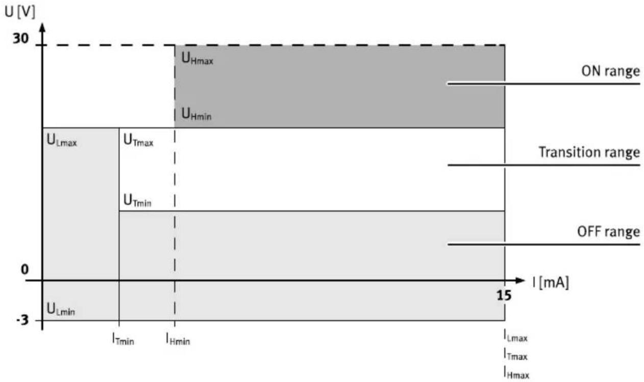
Fig. 13: Operating ranges of digital inputs drawing current
Control inputs #STO-A and #STO-B at [X1A]
| Specification Based on type 3 to EN 61131-2; deviating current con-sumption | |
| Nominal voltage [V DC] 24 | |
| permissible voltage range^1) [V DC]-3 ... | 30 |
| Max. input voltage, high level [V] 28.8 (U_H max) | |
| Min. input voltage, high level [V] 17 (U_H min) | |
| Max. input voltage, low level [V] 5 (U_L max) | |
| Min. input voltage, low level [V]-3 (U_L min) | |
| Max. input current with high [mA] 75level ( I_H max ) | |
| Min. input current with high [mA] 50level ( I_H min ) | |
| Max. input current with low [mA] 75level ( I_L max ) | |
| Min. input current in transition range ( I_T min ) [mA] 1.5 | |
| Tolerance for low test pulses | |
| Tolerated low test pulses [ms] 1 (t_STO,TP) up to max. | |
| Min. time between [ms] 200low test pulses at U_H min < U_STO-A/B ≤ 20 V | |
| Min. time between low test [ms] 100pulses at U_STO-A/B > 20 V | |
Control inputs #STO-A and #STO-B at [X1A]
| Tolerance for high test pulses^2) | |
| Tolerated high test pulses [ms] 1 (tSTO,TP) up to max. | |
| Min. time between high test [ms] 200 pulses at U_STO-A/B < U_Lmax | |
1) Every channel has a separate overvoltage monitor for the power supply at the input. If the voltage at the input exceeds the permissible maximum value, the channel is shut down.
2) High test pulses must never occur simultaneously at inputs #STO-A and #STO-B but only with a time offset.
Tab. 25: Control inputs #STO-A and #STO-B at [X1A]
Control inputs #SBC-A and #SBC-B at [X1A]
| Specification Based on type 3 to EN 61131-2 | |
| Nominal voltage [V DC] 24 | |
| Permissible voltage range [V DC]-3 ... 30 | |
| Max. input voltage, high level [V] 30 (UH max) | |
| Min. input voltage, high level [V] 13 (UH min) | |
| Max. input voltage, low level [V] 5 (UL max) | |
| Min. input voltage, low level [V]-3 (UL min) | |
| Max. input current with high level (IH max) [mA] 15 | |
| Min. input current with high level (mA) 5 level (IH min) | |
| Max. input current with low level (IL max) [mA] 15 | |
| Min. input current in transition range (IT min) [mA] 1.5 | |
| Tolerance for low test pulses | |
| Tolerated low test pulses [ms] 1 (tsBC,TP) up to max. | |
| Min. time between low test pulses at UH min < USBC-A/B ≤ 20 V [ms] 200 | |
Control inputs #SBC-A and #SBC-B at [X1A]
| Min. time between low test [ms] 100 pulses [ms] at U_SBC-A/B >20 V | |
| Tolerance for high test pulses^1) | |
| Tolerated high test pulses [ms] 1 ( t_SBC,TP ) up to max. | |
| Min. time between high test [ms] 200 pulses at U_SBC-A/B < U_Lmax | |
1) High test pulses must never occur simultaneously at inputs #SBC-A and #SBC-B but only with a time offset.
Tab. 26: Control inputs #SBC-A and #SBC-B at [X1A]
Diagnostic outputs STA and SBA at [X1A]
| Design Asymmetrical push-pull output | |
| Voltage range [V DC] 18 ... 30 | |
| Permissible output current [mA] 15 for high level | |
| Voltage loss at high level [V] < 3 | |
| Permissible output current [mA] < -400 for low level1) | |
| Voltage loss at low-level [V] < 1.5 | |
| Pull down resistor [kΩ] < 50 | |
| Protective function | - short-circuit proof- feedback-proof- overvoltage-proof up to 60 V |
| Loads | |
| Resistive load (min.) [kΩ] 1.2 | |
| Inductive load [μH] < 10 | |
| Capacitive load2) [nF] < 10 | |
| Test pulses | |
| Test pulses at outputs | None (for time-offset test pulses on the associated A/B control inputs) |
1) Current flows from outside via the internal low-side switch to 0 V reference potential of 24 V supply
2) Requires connection of the output to a Type 3 input
Tab. 27: Diagnostic outputs STA and SBA at [X1A]
9.3.3 Inputs and outputs for the axis [X1C]
Output BR-EXT at [X1C]
| Design High-Side-Switch | 1) |
| Voltage range [V DC] 18 ... 30 | |
| Permissible output current [mA] 100 for high level | |
| Voltage loss at high level [V] < 3 | |
| Pull down resistor [kΩ] < 50 | |
| Protective function | - short-circuit proof- feedback-proof- overvoltage-proof up to 60 V- Thermal overload protection |
| Error detection Voltage at output despite brake having shut down Diagnostics possible via: -Output SBA-Error message on device | |
| Test pulse length The test pulses for control input #SBC-B are mapped to the output. | |
| Min. time between test [ms] 100 pulses | |
| Loads | |
| Resistive load (min.) [Ω] 240 | |
| Inductive load [mH] | < 100 |
| Capacitive load [nF] | < 10 |
1) The test pulses of the associated control input #SBC-B are mapped to BR-EXT subject to a switching delay. Tab. 28: Output BR-EXT
Copyright:
Festo SE & Co. KG
Ruiter Straße 82
73734 Esslingen
Germany
Phone:
+49 711 347-0
- FESTO
- Table of contents
- About this document.... 5
- Safety....5
- Additional information....8
- Product overview.... 8
- Installation.... 22
- Commissioning....27
- Operation.... 30
- Malfunctions....30
- Technical data....31
- About this document
- Target group
- Applicable documents
- Product version
- Product labelling
- Specified standards
- Safety
- Safety instructions
- Safety
- Intended use
- Application areas
- Permissible components
- Foreseeable misuse
- Foreseeable misuse, general
- Foreseeable misuse of the safety sub-function STO
- Foreseeable misuse of the safety sub-function SBC
- Training of qualified personnel
- Product conformity
- Safety engineering approval
- Additional information
- Product overview
- Safety sub-functions
- Function and application
- Safety sub-function STO
- Function and application of STO
- NOTICE
- STO request
- STO feedback via STA diagnostic contact
- Product overview
- Safety sub-function SBC
- Function and application of SBC
- SBC request
- SBC feedback via SBA diagnostic contact
- Testing the safety sub-function SBC
- Evaluation of SBA
- Requirements for the brakes
- Brake test
- Safety sub-function SS1
- Requirements of SS1
- Function and application of SS1
- SS1 feedback
- Cross wiring of several servo drives
- Cross-wiring, example STA
- Safety relay unit
- Interfaces of the PDS
- Installation
- Safety
- WARNING
- Risk of injury due to electric shock.
- i
- Information for operation with safety function
- Installation
- Basic circuitry design
- STO installation
- Inputs and outputs for the safety sub-function STO
- STO connection example
- Information on the sample circuit
- SBC installation
- Inputs and outputs for the safety sub-function SBC
- SBC connection example
- SS1 installation
- Inputs and outputs for the safety sub-function SS1
- Installation for operation without safety sub-function
- Minimum wiring for operation without safety sub-function
- Commissioning
- Safety
- Check lists
- Operation
- Malfunctions
- Diagnostics via LED
- Safety LED, status of the safety engineering
- Repair
- Technical data
- Technical data, safety engineering
- Remarks
- General technical data
- Technical data, electrical
- Motor auxiliary connection [X6B]
- Inputs, outputs, ready contact at [X1A]
- Operating ranges of digital inputs drawing current
- Inputs and outputs for the axis [X1C]
Brand : Festo
Model : CMMT-AS-C18-11A-P3-MP-S1
Category : Uncategorized