
CRDSNU-20-25-P-A - Uncategorized Festo - Free user manual and instructions
Find the device manual for free CRDSNU-20-25-P-A Festo in PDF.


| Product Type | Pneumatic Cylinder (Double-acting, standard) |
| Model | CRDSNU-20-25-P-A |
| Manufacturer | Festo |
| Piston Diameter | 20 mm |
| Stroke Length | 25 mm |
| Pneumatic Port | M5 |
| Piston Rod Thread | M10x1.25 |
| Operating Pressure | 1 to 10 bar |
| Ambient Temperature | -20 to +80 °C |
| Theoretical Force at 6 bar (Advance) | 188 N |
| Theoretical Force at 6 bar (Return) | 158 N |
| Basic Weight | 310 g |
| Additional Weight per 10 mm Stroke | 7 g |
| End-Position Cushioning | Elastic cushioning rings/plates at both ends (P) |
| Mounting Position | Any |
| Operating Medium | Compressed air to ISO 8573-1:2010 [7:4:4]; lubricated operation possible |
| Mounting Accessories Recommendation | Use self-aligning rod coupler or guide unit for alignment; shock absorbers for high loads; flow control valves for speed adjustment |
| Position Sensing | Via proximity sensors with mounting kit |
| Maintenance | Maintenance-free due to lifetime lubrication; clean with soft cloth; avoid aggressive cleaners |
| Intended Use | Transport of loads |
| Standards Compliance | ISO 8573-1:2010 [7:4:4] for compressed air quality |
Frequently Asked Questions - CRDSNU-20-25-P-A Festo
User questions about CRDSNU-20-25-P-A Festo
0 question about this device. Answer the ones you know or ask your own.
Ask a new question about this device
Download the instructions for your Uncategorized in PDF format for free! Find your manual CRDSNU-20-25-P-A - Festo and take your electronic device back in hand. On this page are published all the documents necessary for the use of your device. CRDSNU-20-25-P-A by Festo.
USER MANUAL CRDSNU-20-25-P-A Festo
natural_image
Technical line drawing of a mechanical component with no visible text or symbolsFESTO
Festo SE & Co. KG
Ruiter Straße 82
73734 Esslingen
Germany
+49 711 347-0
www.festo.com
Operating instructions
8143197
2021-01c
[8143199]

Translation of the original instructions
© 2021 all rights reserved to Festo SE & Co. KG
1 Applicable documents
i
All available documents for the product → www.festo.com/sp.
2 Safety
2.1 Safety Instructions
– Take into consideration the ambient conditions at the location of use.
- Only use the product in original status without unauthorised modifications.
– Observe labelling on the product.
- Store the product in a cool, dry, UV-protected and corrosion-protected environment. Ensure that storage times are kept to a minimum.
– Prior to mounting, installation and maintenance work: Switch off compressed air supply and secure it from being switched back on.
- Observe tightening torques. Unless otherwise specified, the tolerance is ± 20% .
2.2 Intended use
The product is intended for the transport of loads.
2.3 Training of skilled personnel
Installation, commissioning, maintenance and disassembly should only be conducted by qualified personnel.
3 Further information
- Accessories → www.festo.com/catalogue.
– Spare parts → www.festo.com/spareparts.
4 Service
Contact your regional Festo contact person if you have technical questions
→ www.festo.com.
5 Product overview
5.1 Function
The piston rod moves outwards when the cylinder chamber is pressurised. The advanced piston rod is retracted as follows:
- For double-acting cylinders, by pressurising the other cylinder chamber.
The cylinder force during advance and return is:
– different with piston rod at one end.
– identical with through piston rod.
The position of the piston can be detected by proximity switches.
5.2 Design
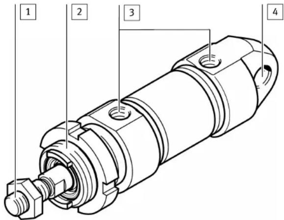
1 Male thread on the piston rod for mounting the payload
2 Male thread on the bearing cap for mounting
3 Supply ports in the bearing/end cap
4 Cross hole for mounting
Fig. 1 Sample illustration CRDSNU
5.3 Mounting
- Handle the cylinder so as to avoid any damage to the cylinder barrel and piston rod.
- Observe the following points:
– parallel mounting when using external guides
- installation without distortion
- Compliance with the permissible loads www.festo.com/catalogue
- Observe tightening torque of lock nuts on the male thread 2.
Size 12 16 20 25 32 40 50 63 80 100
Tightening torque [Nm] 15 15 40 40 60 80 100 100 550 550 on the bearing cap
Tab. 1 Tightening torques on the bearing cap
- Avoid mechanical alignment inaccuracies between the piston rod and an external guide using one of the following measures:
- absolutely precise alignment (general)
– use of a self-aligning rod coupler FK
– use of a guide unit FEN with compensating coupling
A rigid coupling impairs the service life and function of the cylinder.
5.4 Mounting Accessories
In the case of a large payload, high piston speed or when using quick exhaust valves:
- Use suitable shock absorbers or external stops.
To prevent the payload from sliding down suddenly in the event of an air supply failure in a horizontal or sloping mounting position: - Use piloted check valves.
To set the speed:
- Use one-way flow control valves in the following supply ports:
- For single-acting cylinders: GRLZ (supply air)
- For double-acting cylinders: GRLA (exhaust air)
The one-way flow control valves are screwed directly into the supply ports. Use of other accessories with a screw-in depth that is too long will damage the cushioning piston.
For position sensing with proximity sensors:
- Use proximity sensors with mounting kit.
Avoid external influence caused by magnetic or ferritic parts in the vicinity of the proximity sensors (spacing ≥ 10 mm).
6 Installation
6.1 Pneumatic Installation
- Connect tubing to supply ports.
7 Commissioning
7.1 Preparation
- Pressurise the system slowly. A soft start valve is used for gradual start-up pressurisation www.festo.com/catalogue.
With medium or large payloads or at high speeds:
- Use sufficiently large arrester fixtures. The product will tolerate the maximum velocities and payloads without external arrester fixtures
→ www.festo.com/catalogue
7.2 Processing
NOTICE!
Risk of collision due to payloads that project into the setup region of the product.
- Only turn adjusting screws while the product is stationary.
-
First of all, close the one-way flow control valves on both sides completely, then unscrew them one complete turn.
-
Pressurise the cylinder simultaneously at both ends. The piston rod moves slightly to a point of balance.
-
Exhaust the cylinder at one end. The piston rod moves to an end position.
-
Start the test run.
-
If the piston rod strikes hard against the end positions or rebounds, correct the speed using the one-way flow control valve.
8 Maintenance
8.1 Cleaning
NOTICE!
- Do not use aggressive cleaning agents.
- Do not clean the guide elements. Regularly removing the lubricant from the surface of the piston rod reduces the service life.
- Clean the product with a soft cloth.
The cylinder is furthermore maintenance-free owing to the lifetime lubrication.
9 Malfunctions
9.1 Fault clearance
Fault description Cause Remedy
| Irregular movement of the piston rod (cylinder jolts). | Lack of lubricant. Apply lubricant | in accordance with wearing parts sheet → www.festo.com/spareparts. |
| One-way flow control valves restrict the flow of supply air. | Control the exhaust air flow if possible (not the supply air). | |
| Piston rod is dirty. – Clean the cylinder. – Provide covering (relubricate after thorough cleaning). | ||
| Insufficient supply air (stick slip) | - Keep the tubing lines short and select suitable cross-sections. - Select correct pressure. - Keep pressure constant. | |
| Pressure is too low. Connect volume upstream. | ||
| Guide is not parallel to direction of stroke. | Use self-aligning rod coupler as in accessories → www.festo.com/catalogue. | |
| Piston does not travel to end position. | Cylinder barrel is damaged. Replace cylinder. | |
| Setting screw for end-position cushioning is completely closed. | Loosen setting screw. | |
| Foreign matter in the cylinder. Filter the compressed air. | ||
| Cylinder travels to an external end stop. | Readjust the end stop. | |
| False triggering during position sensing. | Temperatures too high or too low. | Comply with permissible temperature range of the proximity sensors. |
| Fault at proximity sensor → Instruction manual for proximity sensor | ||
Tab. 2 Fault clearance
10 Disposal
ENVIRONMENT!
Send the packaging and product for environmentally sound recycling in accordance with the current regulations www.festo.com/sp.
11 Technical data
| Size 12 16 20 25 32 | ||||||
| Pneumatic port | M5 | G1/8 | ||||
| Piston rod thread | M6 | M8 M10x1.25 | ||||
| End-position cushioning | P | elastic cushioning rings/plates, at both ends | ||||
| PPS | - | pneumatic cushioning, both ends, self-adjust-ing | ||||
| PPV | - | pneumatic cushioning, both ends,adjustable | ||||
| Mounting position | any | |||||
| Operating medium | Compressed air according to ISO 8573-1:2010 [7:4:4] | |||||
| Notes on theoperating/pilot medium | lubricated operation possible (in which case lubricatedoperation will always be required) | |||||
| Operating pressure | [MPa]0 | 1 ... 1 | ||||
| [psi]14 | 5 ... 145 | |||||
| [bar] | 1 ... 10 | |||||
| Ambient temperature | ||||||
| CRDSNU-... | [°C] | -20 ... +80 | ||||
| CRDSNU-...-A1 | [°C] | 0 ... +80 | ||||
| CRDSNU-...-S6 | [°C] | 0 ... +120 | ||||
| CRDSNU-...-TT | [°C] | -40 ... +80 | ||||
| Theoretical force | ||||||
| Theoretical force at 0.6 MPa(87 psi, 6 bar), advance | [N] | 68 | 121 | 188 | 295 | 483 |
| Theoretical force at 0.6 MPa(87 psi, 6 bar), return | [N] | 51 | 104 | 158 | 247 | 415 |
| Weight | ||||||
| Basic weight | [g] | 101 | 130 | 310 | 410 | 670 |
| Additional weight per 10 mm stroke | [g] | 4 | 5 | 7 | 11 | 15 |
Tab. 3 Technical data CRDSNU
| Size 40 50 63 80 100 | ||||||
| Pneumatic port | G1/4 | G3/8 | G1/2 | |||
| Piston rod thread | M12x1.25 | M16x1.5 | M20x1.5 | |||
| End-position cushioning | P | elastic cushioning rings/plates, at both ends | ||||
| PPS | pneumatic cushioning, both ends, self-adjusting | |||||
| PPV | pneumatic cushioning, both ends, adjustable | |||||
| Mounting position | any | |||||
| Operating medium | Compressed air according to ISO 8573-1:2010 [7:4:4] | |||||
| Notes on the operating/pilot medium | lubricated operation possible (in which case lubricated operation will always be required) | |||||
| Operating pressure | [MPa] 0 | 1 ... 1 | ||||
| [psi] 14 | 5 ... 145 | |||||
| [bar] | 1 ... 10 | |||||
| Ambient temperature | ||||||
| CRDSNU-... | [°C] | -20 ... +80 | ||||
| CRDSNU-...-A1 | [°C] | 0 ... +80 | ||||
| CRDSNU-...-S6 | [°C] | 0 ... +120 | ||||
| CRDSNU-...-TT | [°C] | -40 ... +80 | ||||
| Theoretical force | ||||||
| Theoretical force at 0.6 MPa (87 psi, 6 bar), advance | [N] | 754 | 1178 | 1870 | 3016 | 4712 |
| Theoretical force at 0.6 MPa (87 psi, 6 bar), return | [N] | 633 | 990 | 1682 | 2721 | 4418 |
| Weight | ||||||
| Basic weight | [g] | 1327 | 2020 | 2943 | 5891.2 | 8527.1 |
| Additional weight per 10 mm stroke | [g] | 24 | 40 | 44 | 68 | 75 |
Tab. 4 Technical data CRDSNU
- Applicable documents
- Safety
- Safety Instructions
- Intended use
- Training of skilled personnel
- Further information
- Service
- Product overview
- Function
- Mounting
- Mounting Accessories
- Installation
- Pneumatic Installation
- Commissioning
- Preparation
- Processing
- NOTICE!
- Maintenance
- Cleaning
- Malfunctions
- Fault clearance
- Disposal
- ENVIRONMENT!
Brand : Festo
Model : CRDSNU-20-25-P-A
Category : Uncategorized