
CH123E - Thermostat Fantini Cosmi - Free user manual and instructions
Find the device manual for free CH123E Fantini Cosmi in PDF.


| Product Type | Thermostat |
| Brand | Fantini Cosmi |
| Model | CH123E |
| Dimensions | 85 x 85 x 30 mm |
| Weight | 200 g |
| Power Supply | 2 x AA batteries (not included) |
| Display | LCD, white backlight |
| Temperature Range | 5°C to 35°C |
| Accuracy | ±0.5°C |
| Programming | Weekly programmable with 4 time slots per day |
| Functions | Manual, auto, holiday mode, frost protection |
| Compatibility | Gas boilers, electric heaters, heat pumps |
| Mounting | Wall mount (screws and dowels included) |
| Protection Rating | IP20 |
| Material | ABS plastic, white |
| Maintenance | Clean with a soft, dry cloth. Do not use solvents. |
| Safety | Designed for indoor use only. Keep away from water sources. |
| Spare Parts & Repairability | Batteries user-replaceable. No other user-serviceable parts. |
| General Information | Electronic thermostat for residential heating control. |
Frequently Asked Questions - CH123E Fantini Cosmi
User questions about CH123E Fantini Cosmi
0 question about this device. Answer the ones you know or ask your own.
Ask a new question about this device
Download the instructions for your Thermostat in PDF format for free! Find your manual CH123E - Fantini Cosmi and take your electronic device back in hand. On this page are published all the documents necessary for the use of your device. CH123E by Fantini Cosmi.
USER MANUAL CH123E Fantini Cosmi
cover plate not included
CH123E
ENG
FLUSH MOUNTING THERMOSTAT 230V
INSTALLATION AND USER MANUAL
FLUSH MOUNTING THERMOSTAT 230V
Dear customer, thank you for purchasing the Fantini Cosmi flush mounting thermostat, model CH123E.
This manual contains all the information required for a correct installation and configuration.
You can also download this manual in digital format and in several languages by framing the QR code below and entering the product code.
ITALIANO
ENGLISH
FRANÇAIS
ESPAÑOL
DEUTSCH
РУССКИЙ
УКРАЇНСЬКИЙ
Warnings

Carefully read the installation instructions, safety warnings, operating modes and maintenance instructions in this booklet, which should be kept for further reference.
- After removing the packaging, check the integrity of the appliance; if in doubt, do not use it.
- Installation of the appliance should only be carried out by qualified technicians in compliance with current standards.
- The use of any electrical appliance involves observing certain basic rules. In particular:
- DO NOT touch the device with wet hands or wet feet or bare feet.
- DO NOT expose the device to the weather (rain, sun, etc.).
- Before carrying out any maintenance or cleaning work, switch off the power supply.
• DO NOT power the appliance with the cover open.
INDEX
- TECHNICAL FEATURES ...... pag. 4
- INSTALLATION pag. 5
- ELECTRICAL CONNECTIONS ...... pag. 7
- DISPLAY AND KEYS DESCRIPTION ...... pag. 8
- OPERATION ...... pag. 8
- THERMOSTAT CONFIGURATION ...... pag. 11
- MAINTENANCE ...... pag. 13
- DISPOSAL ...... pag. 13
Contents of package
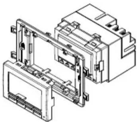
1 thermostat
1 frames
■ 1 white covers, type A
2 screws
1 user manual
natural_image
Technical line drawing of an electrical connector assembly (no text or symbols visible)1 - TECHNICAL FEATURES
| Power supply 230V 50Hz | |
| Contact range 5(3)A 250V~voltage-free switching | |
| Maximum room temperature T45 °C | |
| Temperature adjustment scale 2 ÷ 40 °C, increase 0.1°C | |
| Measurement scale/room T display -40 ÷ 50 °C | |
| Type of action 1B microdisconnection | |
| Degree of protection IP20 | |
| Pollution degree 2 | |
| Pulse voltage 4000V | |
| Electric insulation | Double insulation |
| Software Class A | |
| Thermal gradient of reference 4K/h | |
| Assembly recessed in 3-module box type 503,with 2 screws | |
| Dimensions 68 x 52.2 x 58 mm | |
| Compliant with standards EN 60730-1 and second parts | |
| ErP classification | ErP Class IV; 2% (Reg. EU 811/2013- 813/2013) |
Product not manufactured in Italy.
2 - INSTALLATION
The CH123E thermostat must be installed in a 3-module recessed box, in the middle of the apartment, preferably 1.5 m off the ground. The required components, all included in the package according to the following table.
| MODELS COVER | TYPE | FRAME TYPE | TABS TO DETACH | COVER COLOR | ADAPTERS KIT ** |
| Bticino Matix GO A 3 | YES position “A+C” | white -- | |||
| silver | Code 1576891 | ||||
| Bticino Living Now A 4** NO | white | Code 1576895 | |||
| black | Code 1576896 | ||||
| sand | Code 1576897 | ||||
| Vimar Eikon Evo A 3 | YES position “A+D” | white | -- | ||
| Vimar Arké A 3 NO white | -- | ||||
| Vimar Linea C** 3 | YES position “A+C+D” | white | Code 1576892 | ||
| black | Code 1576893 | ||||
| sand | Code 1576894 |
Frame n. 4 (optional) Frame n. 3
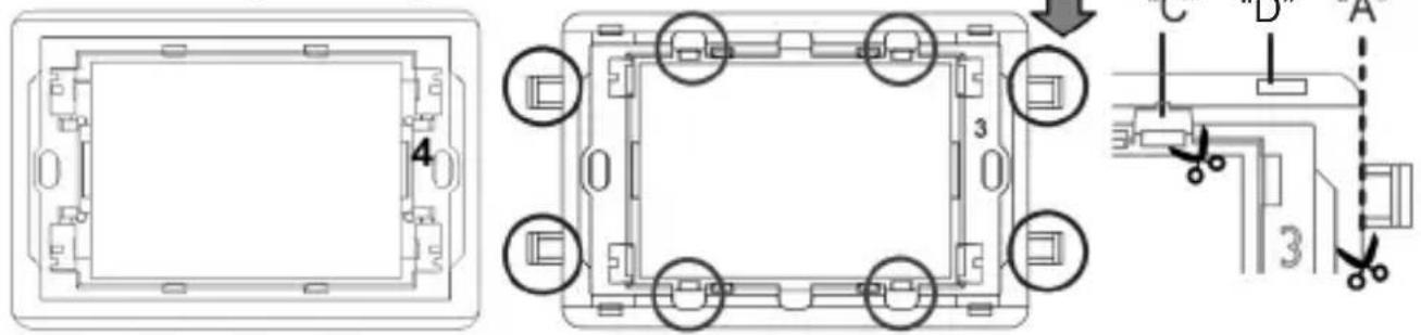
cut 8 or 12 tabs
according to type of cover plate


Installation and maintenance operations must be carried out with the system's electrical power switched off and by qualified personnel, in compliance with the regulations in force.
PERFORM THE FOLLOWING OPERATIONS:
- act on the master switch on the electric panel to cut power to the electrical system;
- when required, detach the tabs according to the type of plate;
- fasten the thermostat to the suitable frame;
- mount the cover on the body of the thermostat.
- connect the two wires of the boiler to terminals 1-2 of CH123E;
- screw the frame onto the box using the provided screws;
- mount the plate;
- switch the electric system back on.
3 - ELECTRICAL CONNECTIONS


Installation and maintenance operations must be carried out with the system's electrical power switched off and by qualified personnel, in compliance with the regulations in force.
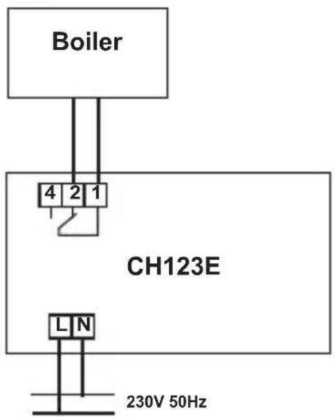
PLEASE NOTE: when CH123E is disconnected, the boiler contact remains in its current position.
During black-outs, the programmed parameters will not be lost as the settings are stored in a non-volatile memory.
4 - DISPLAY AND KEYS DESCRIPTION
The thermostat is equipped with 4 keys, the function of which varies depending on the situation. It is described by the symbol which appears on the display next to the key.
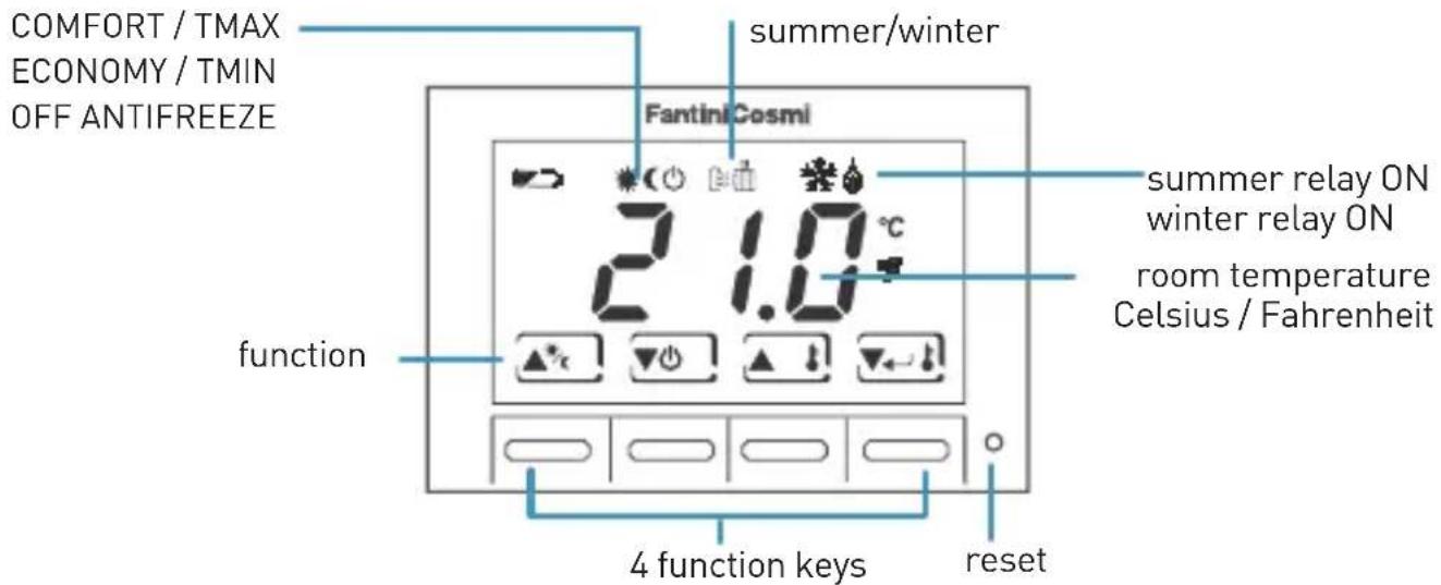
N.B.: the first press of a key only turns on the display light to allow for better viewing.
5 - OPERATION
SUMMER/WINTER SELECTION
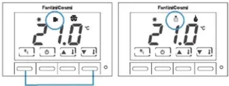
Press both keys simultaneously to select SUMMER (cooling) or WINTER (heating) mode.
When you have set the operating mode ,press the two keys (increase or decrease ▼) to set the temperature:
ECONOMY / TMIN 2 ÷ 40 °C
COMFORT / TMAX 2 ÷ 40 °C
OFF ANTIFREEZE 0 ÷ 7 °C
ANTIFREEZE temperature cannot be set in summer mode.
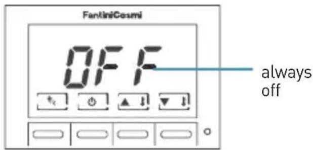
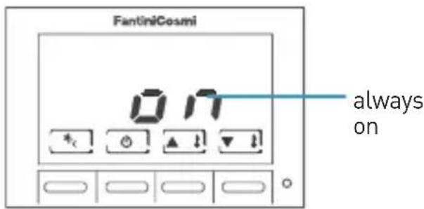
Press together, and keep pressed, to change back lighting duration.
Increase\decrease back lighting duration pressing or and while keeping ECONOMY/COMFORT and ON/OFF keys pressed.
You may choose the time during which back lighting remains on:
OFF → always off
1 sec. ... 10 sec.
ON → always off
6 - THERMOSTAT CONFIGURATION

ATTENTION: only qualified personnel may configure the device.
Configuring the thermostat allows you to customise the device's operating parameters. Perform the following steps to access the configuration program:
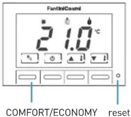
1 Using a sharp object, press the reset button while holding down the "COMFORT/ECONOMY" button at the same time.
2 When the display reads P01, release the "COMFORT/ECONOMY" button.
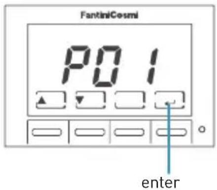
The display represents the configuration parameters by an index: P01, P02....
Press ▲ or ▼ scroll the parameter indexes.
Press to edit a parameter. Use and to change the value of the parameter. Press again to go back to the parameter index.
To exit parameter configuration, press ▲ or ▼ until the display reads "END". Press ←.
Index Parameter Default Values
| P01 display mode 1 1 = view room temp | |
| 2 = view set point | |
| P02 correction of displayed temperature value | 0.0°C +/- 4°C (step 0.1°C) |
| P03 winter lower limit set point temperature | 2.0°C 2.0°C......40.0°C (step 1.0°C) |
| P04 winter upper limit set point temperature | 40.0°C 2.0°C......40.0°C (step 1.0°C) |
| P05 summer lower limit set point temperature | 2.0°C 2.0°C......40.0°C (step 1.0°C) |
| P06 summer upper limit set point temperature | 40.0°C 2.0°C......40.0°C (step 1.0°C) |
| P07 differential adjustment 0.3°C ±0.3°C......±2.0°C * (step 0.1°C) | |
| P08 temperature scale CEL CEL = Celsius | FAH = Fahrenheit |
| END exit parameter configuration and store values | |
* ± 0.3°C value suited for plants with slow thermal inertia, ± 2°C value suited for very reactivate plants.
7 - MAINTENANCE
Use only a soft and dry cloth to clean the device. Do not use water or other liquid substances.
6 - DISPOSAL

natural_image
Symbol of a trash bin crossed with a diagonal line and a horizontal bar below (no text or labels)Symbol of the crossed-out wheeled bin indicates that the product must be collected and disposed of separately from household waste. Batteries and the integrated accumulators may be disposed of together with the product. They will be separated at the recycling facilities. A black bar indicates that the product was placed on the market after August 13th, 2005. Participating in the separate collection of products and batteries contributes to the correct disposal of these materials and therefore avoids possible negative consequences for the environment and human health. For more detailed information on the collection and recycling programs available in your country, contact the local authorities or the sales point where you purchased the product.

FANTINI COSMI S.p.A.
Brand : Fantini Cosmi
Model : CH123E
Category : Thermostat