
Professional 3.0 PKC3 - Range hood BORA - Free user manual and instructions
Find the device manual for free Professional 3.0 PKC3 BORA in PDF.


| Product Type | Range Hood |
| Model | Professional 3.0 PKC3 |
| Brand | BORA |
| Width | 90 cm |
| Depth | 60 cm |
| Height (min-max) | 60 - 110 cm |
| Weight | 22 kg |
| Power Supply | 230 V / 50 Hz |
| Total Motor Power | 250 W |
| Max Extraction Rate | 750 m³/h |
| Noise Level (max) | 55 dB(A) |
| Control Type | Touch Slider |
| Lighting | Integrated LED, 2 x 3 W |
| Grease Filter | Stainless steel, washable |
| Carbon Filter | Optional, for recirculation mode |
| Ducting | 150 mm diameter |
| Installation | Under cabinet or wall-mounted |
| Energy Class | A+ |
| Annual Energy Consumption | 35 kWh/year |
| Grease Filter Cleaning | Every 2-4 weeks in dishwasher |
| Carbon Filter Replacement | Every 6-12 months |
| Warranty | 2 years |
Frequently Asked Questions - Professional 3.0 PKC3 BORA
User questions about Professional 3.0 PKC3 BORA
0 question about this device. Answer the ones you know or ask your own.
Ask a new question about this device
Download the instructions for your Range hood in PDF format for free! Find your manual Professional 3.0 PKC3 - BORA and take your electronic device back in hand. On this page are published all the documents necessary for the use of your device. Professional 3.0 PKC3 by BORA.
USER MANUAL Professional 3.0 PKC3 BORA
EN Operating instructions Professional 3.0
natural_image
Black-and-white photo of two stainless steel cookware pots on a stovetop with circular control buttons, emitting steam (no text or symbols visible)Contents
1 General information 4
1.1 Validity of the operating and installation instructions ....4
1.2 Liability ...... 4
1.3 Product conformity 4
1.4 Data protection ....4
1.5 Presentation of information ....4
1.5.1 Safety and warning instructions 4
1.5.2 Figures.... 4
2 Safety 5
2.1 Intended use ....5
2.2 People with limited abilities ....5
2.3 General safety instructions ....5
2.4 Safety instructions - operation.... 6
2.4.1 Safety instructions - cooktop extractor operation..... 7
2.4.2 Safety instructions - cooktop operation.... 8
2.5 Safety instructions – cleaning and maintenance ..... 9
2.5.1 Safety instructions – cleaning and maintenance of cooktop extractors 10
2.5.2 Safety instructions – cleaning and maintenance of cooktops.... 10
2.6 Safety instructions – repairs, servicing and spare parts ....10
3 Appliance description 11
3.1 Model description ..... 11
3.1.1 Professional 3.0 cooktop extractors.... 11
3.1.2 Professional 3.0 cooktops 11
3.2 Control knob....11
3.3 Cooktop extractor appliance description .....12
3.3.1 Installation variations.... 12
3.3.2 Cooktop extractor display and symbols.... 12
3.3.3 Structure of the cooktop extractors 12
3.3.4 Sensors 13
3.3.5 Interface for external devices 13
3.3.6 USB port for servicing.... 13
3.4 Cooktop appliance description 13
3.4.1 Display and symbols 13
3.4.2 Layout and size of the cooking zones 14
3.4.3 How the induction cooktops work 16
3.4.4 How the Hyper and HiLight cooktops work.... 17
3.4.5 How the Tepan stainless steel grill works 17
3.4.6 How the gas cooktop works 17
3.5 Safety features....18
3.5.1 Anti-trap protection 18
3.5.2 Safety shut-down.... 18
3.5.3 Residual heat indicator 19
3.5.4 Overheating protection.... 19
3.5.5 Child lock.... 19
4 Overview of features and functions 20
5 Functions and operation 21
5.1 Knob operation....21
5.1.1 Operating the knob ring.... 21
5.1.2 Operating the touch surface 21
5.2 Switching the system on and off....21
5.2.1 Switching on.... 21
5.2.2 Switching off.... 21
5.3 Operating the cooktop extractor .....22
5.3.1 General operating instructions for the cooktop extractor.... 22
5.3.2 Setting the fan power level 22
5.3.3 Fan power setting 22
5.3.4 Automatic after-run 22
5.4 Cooktop extractor function menu....22
5.4.1 Cooktop extractor cleaning function.... 23
5.4.2 Short-time timer 23
5.4.3 Automatic extractor function.... 24
5.4.4 Child lock.... 25
5.4.5 Filter service life and filter service display 25
5.5 Operating the cooktops....26
5.5.1 General operating instructions for cooktops...... 26
5.5.2 Special operating instructions for the Tepan stainless steel grill.... 27
5.5.3 Special operating instructions for the gas cooktop... 27
5.5.4 Setting cooking zone power levels.... 28
5.5.5 Cooktop power setting 28
5.5.6 Bridging function 28
5.5.7 Pause function.... 29
5.5.8 Pan size recognition.... 29
5.6 Cooktop function menu 29
5.6.1 Calling up the function menu.... 30
5.6.2 Additional ring switching - 2-ring, 3-ring, roaster ..... 30
5.6.3 Variable heat retention function 30
5.6.4 Cooking zone timer.... 31
5.6.5 Automatic heat up function 32
5.6.6 Cleaning function.... 33
6 Configuration menu 34
6.1 Menu overview....34
6.2 How to use the menu....34
6.2.1 Calling up the menu.... 34
6.2.2 Calling up the gas cooktop menu 34
6.2.3 Entering settings.... 34
6.2.4 Closing the menu.... 34
6.3 Initial operation....34
6.3.1 Basic configuration 35
6.4 Description of the other menu items....35
6.4.1 Menu item C0: Volume of the acoustic signals..... 35
6.4.2 Menu item C1: Demo mode.... 35
6.4.3 Menu item C2: Speed of the cover flap motors ..... 35
6.4.4 Menu item C5: Manual operation of the cover flap motors 36
6.4.5 Menu item C6: switching fan PWM values 36
6.4.6 Menu item C7: Installation of left cooktop 0°/180° 36
6.4.7 Menu item C8: Installation of right cooktop 0°/180° 36
6.4.8 Menu item C9: Pause function activated/deactivated 36
6.4.9 Menu item Cb: software update 36
6.4.10 Menu item Cc: data export 38
6.4.11 Menu item Cd: software version indicator 38
6.5 Gas configuration menu item....39
6.5.1 Menu item CE: GPU configuration 39
6.5.2 Menu item CF: Gas burner characteristic curves..... 39
6.5.3 Menu item Ch: GPU reset 39
7 Cleaning and maintenance 40
7.1 Cleaning agents 40
7.1.1 Cleaning products for glass ceramic cooktops ..... 40
7.1.2 Cleaning products for the Tepan stainless steel grill 40
7.2 Cleaning the cooktop extractor ....40
7.2.1 Removing the cover flap, grease filter and filter tray 40
7.2.2 Fitting the cover flap, grease filter and filter tray..... 41
7.2.3 Removing the maintenance tray 41
7.2.4 Installing the maintenance tray.... 41
7.2.5 Cleaning the components.... 42
7.2.6 Ending the cooktop extractor cleaning process...... 42
7.2.7 Replacing the recirculated air filter.... 42
7.3 Cleaning the cooktops....42
7.3.1 Cleaning glass ceramic cooktops 42
7.3.2 Cleaning the surface of the Tepan stainless steel grill 42
7.3.3 Cleaning the components on the gas cooktop..... 43
7.4 Looking after your cooktops ....44
7.5 Cleaning the control knobs ....44
8 Troubleshooting 45
8.1 Cooktop extractor troubleshooting....45
8.2 Cooktop troubleshooting....46
8.2.1 Gas cooktop troubleshooting.... 47
8.3 Dealing with errors 48
9 Warranty, technical service, spare parts, accessories 49
9.1 BORA manufacturer's warranty....49
9.1.1 Warranty extension.... 49
9.2 Service....49
9.3 Spare parts....49
9.4 Accessories ....49
10 Energy data sheets 51
10.1 Energy data sheet for PKA3/PKA3AB....51
10.2 Energy data sheet for PKFI3....52
10.3 Energy data sheet for PKI3....52
10.4 Energy data sheet for PKC3 52
10.5 Energy data sheet for PKCB3 53
10.6 Energy data sheet for PKCH3....53
10.7 Energy data sheet for PKG3 53
11 Identification plates 54
1 General information
These instructions contain important information to protect you from injury and prevent damage to the appliance. Please read these instructions carefully before installing or using the appliance for the first time.
Other documents apply alongside these instructions. Please by all means adhere to all documents that form part of the scope of delivery.
Assembly, installation and commissioning must always occur in line with national laws, regulations and standards. The work must be performed by qualified specialists who know and comply with the additional regulations of the local energy supply companies.
All safety and warning information as well as the handling instructions in the accompanying documents must be observed.
1.1 Validity of the operating and installation instructions
These instructions apply to several appliance versions. It is therefore possible that some of the features described do not apply to your appliance. The details of the figures contained herein may differ from some appliance versions and are to be understood as schematic diagrams.
These instructions apply to the Professional 3.0 product range including the All Black model. To simplify things, the instructions do not include the product numbers for the different models.
1.2 Liability
. BORA Holding GmbH, BORA Vertriebs GmbH & Co KG, BORA APAC Pty Ltd and BORA Lüftungstechnik GmbH – hereinafter referred to as BORA – do not assume any liability for damage arising from disregard for or non-adherence to the documents included in the scope of delivery!
Furthermore, BORA shall not be held liable for damage caused by improper installation or failure to observe the safety and warning information!
1.3 Product conformity
Directives
The appliances meet the following EU/EC directives:
• 2014/30/EU EMC Directive
• 2014/35/EU Low Voltage Directive
• 2009/125/EC Ecodesign Directive
• 2011/65/EU RoHS Directive
Regulations
Gas appliances meet the following EC directives:
• (EU) 2016/426 regulation on appliances burning gaseous fuels
1.4 Data protection
During operation your cooktop extractor saves pseudonymised data such as menu settings entered by you, operating hours of the individual technical units and the number of functions selected.
Furthermore, your cooktop extractor documents errors in combination with the number of operating hours. Data can only be read out manually via your cooktop extractor. This decision is therefore your responsibility. These saved data then enable a rapid error search and troubleshooting in the event of servicing.
1.5 Presentation of information
We use standard formatting, numbering, symbols, safety instructions, terms and abbreviations so that you can work quickly and safely when using this manual. The article described in these instructions is hereinafter also referred to as an appliance.
Instructions are indicated with an arrow.
▶ Always follow all instructions in the prescribed order.
Enumerations are indicated with a bullet point at the start of the line:
- Enumeration 1
- Enumeration 2
i Information notes point to special features that must be taken into account.
1.5.1 Safety and warning instructions
The safety and warning instructions in this manual are emphasised with symbols and signal words. Safety and warning instructions are structured as follows:
DANGER
Type and source of danger
Results of non-compliance
▶ Measures to minimise risk
Please note:
- warning symbols draw attention to a high risk of injury.
● The signal word indicates the severity of that risk.
| Warning symbol | Signal word Risk |
| Danger Indicates an immediate, hazardous situation which causes death or serious injury if not respected. | |
| Warning Indicates a potentially hazardous situation which can cause death or serious injury if not respected. | |
| Caution Indicates a potentially hazardous situation which can cause death or serious injury if not respected. | |
| Note Indicates a potentially hazardous situation which can cause property damage if not respected. |
Tab. 1.1 Meaning of the warning symbols and signal words
1.5.2 Figures
All measurements are provided in millimetres.
2 Safety
The appliance complies with the stipulated safety requirements. The user is responsible for the safe use of the appliance, cleaning and maintenance. Improper use can lead to personal injury and damage to property.
2.1 Intended use
The appliance is solely intended for preparing food in private households.
This appliance is not intended for:
- outdoor use
- heating rooms
• cooling, ventilating or dehumidifying rooms - use in mobile installation sites such as motor vehicles, ships or aeroplanes
- use with an external timer or a separate remote control system (except for emergency shutdown in the case of the cooktop extractor)
- use at altitudes of over 2000 m (metres above sea level)
● operation with an extractor hood (where a gas cooktop is installed) - use when not fully installed
Any other use or any use that goes beyond that which is described here is classed as unintended.

BORA does not assume any liability for damages caused by incorrect installation, improper use or incorrect operation.
All misuse is prohibited!
2.2 People with limited abilities
Children
The appliance can be used by children aged 8 and over if they are supervised or have been instructed how to use the appliance safely and understand the resultant risks. Children must not play with the appliance.
▶ Use the childproofing feature in order to prevent children from switching on the appliance or changing the settings when they are unattended.
▶ Supervise children in the vicinity of the appliance.
▶ Do not store any items that could be of interest to children in storage spaces above or behind the appliance. Otherwise, they will be tempted to climb onto the appliance.

Any work involving cleaning and maintenance must not be carried out by children unless they are supervised at all times while doing so.
People with reduced physical, sensory or mental capacities
The appliance can be used by people with reduced physical, sensory or mental capacities or a lack of experience and/or knowledge if they are supervised or have been instructed how to use the appliance safely and understand the resultant risks. Operation can be restricted using the child lock.

DANGER
Risk of burns from hot cookware and food
Handles projecting over the edge of the worktop are asking to be grabbed.
▶ Keep children away from hot cooking zones or ensure they are supervised at all times.
▶ Keep children away from hot cooking zones or ensure they are supervised at all times.
▶ Do not turn pot and pan handles so they stick out beyond the work surface.
▶ Make sure that hot pots and pans cannot be pulled down.
▶ If necessary, use suitable stove guards or covers.
▶ Only use stove guards and covers that are approved by the appliance manufacturer; otherwise, there is a risk of accidents.
To choose a suitable stove guard, contact your specialist retailer or the BORA Service Team.
2.3 General safety instructions

DANGER
Packaging components are a choking hazard
Packaging components (e.g. film, polystyrene) can be life-threatening for children.
▶ Store all packaging components out of reach of children.
▶ Dispose of the packaging properly and immediately.

DANGER
Risk of electric shock or injury from damaged surfaces
The underlying electronics can be exposed or damaged due to fissures, fractures or cracks in appliance surfaces (e.g. damaged glass), particularly in the vicinity of the operating unit. This can cause an electrical shock. Furthermore, a damaged surface can cause injuries.
▶ Do not touch the damaged surface.
▶ If there are any cracks, fissures or fractures, switch the appliance off immediately.
▶ Securely disconnect the appliance from the mains using the circuit breaker, fuses, automatic circuit breakers or contactor.
▶ Contact BORA Service.

WARNING
Risk of injury or damage due to incorrect components or unauthorised modifications
Incorrect components can lead to personal injury or damage to the appliance. Modifications, additions or alterations to the appliance can lead to safety risks.
▶ Only use original components.
▶ Do not make any modifications, additions or alterations to the appliance.

WARNING
Risk of injury due to mechanical damage on the appliance
Mechanical damage (e.g. cracks, deformation, separation of adhesive seals, etc.) to the appliance, as well as to cables and accessories can cause injuries.
▶ Do not operate the appliance.
▶ Do not try to repair or replace damaged components yourself.
▶ Contact BORA Service.
CAUTION
Appliance components can cause injury if dropped
Appliance components can cause injury if you drop them.
▶ Place any appliance components that have been removed in a safe place near the appliances.
▶ Ensure that no components removed from the appliances can fall on the floor.
CAUTION
Risk of injury from heavy lifting
If not handled correctly, carrying and installing appliances can cause injury to the limbs or torso.
▶ If necessary, carry and install the appliance with another person.
▶ Use appropriate aids to prevent damage or injury.
CAUTION
Damage from improper use
The appliance surfaces must not be used as work or storage surfaces. This can damage the appliances (particularly in the case of hard and sharp objects).
▶ Never use the appliances as work or storage surfaces.
▶ Keep hard or sharp objects away from the appliance surfaces.
PLEASE NOTE
Faults and errors
In the event of faults or incorrect use, error messages will be displayed.
In the case of faults and errors, follow the instructions in the “Troubleshooting” chapter.
In the event of any faults or errors that are not mentioned, switch the appliance off and contact BORA Service.
PLEASE NOTE
Appliance damage caused by pets
Pets may damage the appliance or injure themselves.
▶ Keep pets away from the appliance.
2.4 Safety instructions – operation

DANGER
Risk of fire from overheated oil or fat
Oil or fat in the pot can quickly heat up and ignite.
▶ Never leave the appliance unattended when cooking with oil or fat.
▶ Never extinguish oil and fat fires with water.
▶ Switch off the appliance.
Extinguish the fire using a pan lid or a fire blanket, for example.

WARNING
Risk of burning from hot appliances
Certain appliances and their exposed parts become hot during use. They should be left to cool down completely after switching off. Touching hot surfaces can cause serious burns.
▶ Do not touch hot appliances.
▶ Pay attention to the residual heat indicator.

WARNING
Risk of burns due to power cut
During or after a power cut a cooktop that was previously in operation may still be hot.
▶ Do not touch the appliance while it is still hot.
▶ Keep children away from the hot appliance.

WARNING
Risk of burning and fire from hot objects
The appliance and its exposed parts are hot during operation and the cooling phase. Objects in contact with hot appliance components heat up very quickly and can cause severe burns (this particularly applies to metal objects such as knives, forks, spoons, lids or appliance components) or catch fire.
▶ Do not place any items on the appliance.
▶ Please use suitable accessories (pot holders, oven gloves).
▶ Do not simply rely on the pan size recognition function on induction cooktops; always switch the appliance off after use.
CAUTION
Damage caused by hot cookware
Hot cookware can damage certain components in the appliance.
▶ Do not put hot cookware down in the area of the operating panel or cooktop display.
▶ Keep hot cookware away from the air inlet nozzle.
PLEASE NOTE
Appliance damage
Incorrect use may cause damage to the appliance.
▶ Make sure that the base of the cookware as well as the appliance surfaces are clean and dry.
▶ Always lift (do not drag) cookware to prevent scratching and abrasion on the appliance surface.
▶ Do not use the appliance as a storage surface.
▶ Always switch off the appliance after use.
2.4.1 Safety instructions – cooktop extractor operation

DANGER
Risk of smoke inhalation
When the cooktop extractor is used in exhaust air mode, it draws in air from the room it is installed in and from neighbouring rooms. Without sufficient air, there will be a drop in air pressure. When used at the same time as a fireplace that is dependent on the air in the room, noxious gases can be sucked into the living areas from the chimney or outlet shaft.
▶ Make sure that there is always a sufficient air supply.
▶ Only use reliable, tried-and-tested switching devices, (e.g. window contact switch, low pressure warning device) and have them approved by a qualified expert (certified chimney sweep).

WARNING
Fire risk from flambéing
While the cooktop extractor is working, it sucks up grease from cooking. Flambéing food can cause the grease to catch fire.
▶ Clean the cooktop extractor regularly.
▶ Never work with a naked flame while the cooktop extractor is running.
CAUTION
Risk of injury from moving cover flap
There is a risk of injury when the electrical cover flap is moving.
▶ Do not put your hands inside the cooktop extractor while the cover flap is moving.
CAUTION
Damage caused by objects or paper suctioned in
Small and light items, such as cleaning cloths made from material or paper, can be suctioned into the cooktop extractor. This can damage the fan or impair the exhaust performance.
▶ Do not store any items or paper on the cooktop extractor.
▶ Only operate the integrated cooktop extractor with the grease filter fitted.
CAUTION
Damage caused by grease and dirt deposits
Grease and dirt deposits can prevent the cooktop extractor from functioning properly.
▶ Never use the cooktop extractor without a correctly fitted stainless steel grease filter.
PLEASE NOTE
Increased humidity
When cooking, additional moisture is released into the ambient air. In recirculation mode, only a slight amount of moisture is removed from the cooking vapour.
When using the recirculation mode, ensure a sufficient supply of fresh air, e.g. by opening a window.
▶ Ensure a normal and comfortable room climate (humidity of 45 – 60%), e.g. by opening natural ventilation openings or using domestic ventilation systems.
2.4.2 Safety instructions – cooktop operation

DANGER
Danger of fire caused by leaving the cooktop unattended
Oil or fat in the pot can quickly heat up and ignite.
▶ Never leave oil or fat to heat up unattended.
▶ Never extinguish oil and fat fires with water.
▶ Switch off the cooktop.
Extinguish the fire using a pan lid or a fire blanket, for example.

DANGER
Danger of explosion caused by flammable liquids
Flammable liquids in the vicinity of a cooktop can explode and cause serious injury.
▶ Do not spray aerosols near the appliance when it is in use.
Do not place any flammable liquids in the vicinity of a cooktop.

DANGER
Risk of carbon monoxide poisoning
Extractor hoods and other cooking vapour extractors can impair the safe operation of appliances that use gas or other fuels due to the return flow of combustion gases. These gases can lead to carbon monoxide poisoning.
▶ Ensure that exhaust gases are properly removed
▶ Ensure sufficient ventilation is provided during operation.
▶ Always have a qualified specialist check the safe operation of the gas appliance during commissioning.

DANGER
Risk of explosion and asphyxiation from gas
Leaking gas can lead to an explosion and severe injuries, or asphyxiation.
▶ If you smell gas while using the appliance, switch it off immediately.
▶ Keep sources of ignition (naked flames, electric fires) away and do not operate any light switches, or switches on electrical appliances.
▶ Do not remove plugs from sockets (risk of sparking).
▶ Close the gas supply immediately and turn off the mains supply.
▶ Ensure there is a good supply of fresh air (open doors and windows).
▶ Inform Customer Care or your gas installer immediately.

DANGER
Fire risk from naked flame
A naked flame can cause adjacent objects to catch fire.
▶ Turn the gas flame down to the lowest level if you remove pots or pans briefly from the hob.
▶ Never leave a naked flame unattended.
Extinguish any fire using a lid or a fire blanket, for example.
▶ Close the gas supply and turn off the mains supply.

WARNING
Risk of burns from hot cooktop extractor when using gas cooktops
The cooktop extractor and its exposed parts (in particular the cover flap, stainless steel grease filter and grease filter tray) become hot when an adjacent gas cooktop is in use. The cooktop extractor must be left to cool down after the gas cooktop has been switched off. Touching hot surfaces can cause serious burns.
▶ Never touch the cooktop extractor when it is hot.
▶ Keep children away from the cooktop extractor when it is hot or ensure they are supervised at all times.

WARNING
Risk of burns from hot liquids boiling over
Unattended pans can boil over allowing hot liquids to escape.
▶ Keep an eye on pans when cooking.
▶ Avoid over-cooking.
▶ Always switch off the appliance after use.

WARNING
Risk of burns from hot steam
Liquid between the cooking zone and cookware base can evaporate and cause burns.
▶ Make sure that the cooking zone and the cookware base are always dry.
CAUTION
Risk of personal injury and appliance damage due to incorrect gas configuration
If the wrong gas type or pressure are selected in the appliance settings, this may negatively affect the flame.
The gas type and pressure must only be changed by reliable trained specialists who are familiar with and comply with the standard national regulations and supplementary regulations of the local utility companies.
▶ Before connecting the appliance, check that the appliance settings comply with local connection requirements (gas type and pressure).
PLEASE NOTE
Damage caused by sugary and salty foods
Sugary and salty foods and juices can damage the hot cooking zone.
▶ Make sure sugary and salty foods or juices do not get onto the cooking zone while it is hot.
▶ Remove sugary and salty foods and juices from the hot cooking zone immediately.
CAUTION
Electromagnetic radiation
Effect on pace makers, hearing aids and metal implants. Induction cooktops generate a high-frequency electromagnetic field in the area of the cooking zones. The cooking zones may affect pacemakers, hearing aids or metal implants negatively or disturb their function when in close proximity.
▶ If in doubt, contact the manufacturer of your medical device or your doctor.
2.5 Safety instructions – cleaning and maintenance
PLEASE NOTE
Appliance damage due to soiled appliances
Dirt can lead to damage, restriction of functions, or bothersome odours.
▶ Clean the appliance regularly.
▶ Remove dirt immediately.
When cleaning, only use non-abrasive detergents to prevent scratching and abrasion on the surface.
When cleaning, ensure that no water penetrates the appliance. Use only a slightly damp cloth. Never spray the appliance with water. Water penetration can cause damage.
▶ Do not use a steam cleaner for cleaning. Steam can cause a short circuit on live parts and thus lead to property damage.
▶ Please follow all instructions in the “Cleaning and Maintenance” chapter.
2.5.1 Safety instructions – cleaning and maintenance of cooktop extractors

DANGER
Risk of fire from fat deposits
The risk of fire can be increased by failure to clean the grease filter properly and on a regular basis, or if the filter change is overdue.
▶ Clean and replace the filter at regular intervals.
PLEASE NOTE
Appliance damage and malfunctions
Soiled ventilation openings can lead to component damage and malfunctions.
▶ Keep all ventilation openings open and clean.
2.5.2 Safety instructions – cleaning and maintenance of cooktops

WARNING
Risk of burns from hot surfaces
There is a risk of burns when cleaning hot cooktops.
▶ Only clean the cooktops once they have cooled.
▶ Pay attention to the residual heat indicator.
2.6 Safety instructions – repairs, servicing and spare parts

DANGER
Risk of injury when carrying out repairs
Insufficient expertise can lead to injury when carrying out repairs.
The appliance must only be repaired and serviced by trained specialists who are familiar with and comply with the standard national regulations and supplementary regulations of the local utility companies.
▶ Safely disconnect the appliance from the mains supply.
▶ Work on electrical components must only be conducted by trained electrical personnel.
▶ A damaged power supply cable must be replaced by a suitable power supply cable.

WARNING
Risk of injury or damage from improper repairs
Incorrect components can lead to personal injury or damage to the appliance. Modifications, additions or alterations to the appliance can lead to safety risks.
▶ Only use original spare parts for repairs.
▶ Do not make any modifications, additions or alterations to the appliance.
CAUTION
Risk of injury during repair of gas appliances
Insufficient expertise can lead to injury when disassembling the appliance.
The gas connection must only be worked on by reliable trained specialists who are familiar with and comply with the standard national regulations and supplementary regulations of the local utility companies.
3 Appliance description
▶ Observe all safety and warning information (see "2 Safety").
3.1 Model description
3.1.1 Professional 3.0 cooktop extractors
The cooktop extractors are the central components of the whole system and can be combined with all Professional 3.0 cooktops.
i Up to 2 cooktops can be connected to each cooktop extractor.
| Model Long description |
| PKA3 Pro cooktop extractor(flexible system with separate control unit) |
| PKA3AB Pro cooktop extractor, All Black(flexible system with separate control unit) |
| PKAS3 Pro cooktop extractor system with integrated fan(compact system with integrated control unit and integrated fan) |
| PKAS3AB Pro cooktop extractor system with integrated fan, All Black(compact system with integrated control unit and integrated fan) |
Tab. 3.1 Model description
3.1.2 Professional 3.0 cooktops
The cooktops are the modular components of the Professional 3.0 system.
| Model Long description |
| PKFI3 Pro surface induction cooktop |
| PKI3 Pro induction cooktop |
| PKIW3 Pro induction wok cooktop |
| PKC3 Pro HiLight cooktop 3-ring/2-ring |
| PKCB3 Pro HiLight cooktop 3-ring/roaster |
| PKCH3 Hyper cooktop 1-ring/2-ring |
| PKT3 Tepan stainless steel grill with 2 cooking zones |
| PKG3 Pro gas cooktop |
Tab. 3.2 Model description
3.2 Control knob
How it works
The cooktop extractor and cooktops are operated with a control knob. The power levels and functions are controlled by turning the knob ring and pressing the touch surface. How it works and its functions are described in more detail in the "Functions and operation" chapter.
Structure
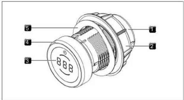
Fig. 3.1 Structure of control knob
[1] Knob housing
[2] Universal nut
[3] Control knob display
[4] Knob ring
[5] Wave spring
Operating elements
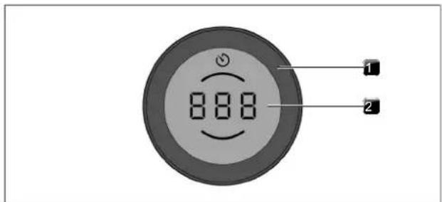
Fig. 3.2 Control knob operating elements
[1] Knob ring
[2] Touch surface
Control knob display
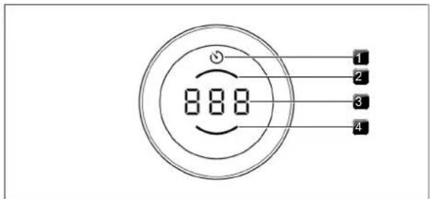
Fig. 3.3 Control knob display elements
[1] Timer/quick timer display
[2] Rear cooking zone indicator
[3] Multi-function display
[4] Front cooking zone indicator
Control knob assignment

Fig. 3.4 Control knob assignment
[1] Control knob for left cooktop, front cooking zone
[2] Control knob for left cooktop, rear cooking zone
[3] Control knob for cooktop extractor
[4] Control knob for right cooktop, front cooking zone
[5] Control knob for right cooktop, rear cooking zone
3.3 Cooktop extractor appliance description
3.3.1 Installation variations
Depending on the model you purchased, the cooktop extractor can be operated as an exhaust air or a recirculating air version.

Exhaust air
The air suctioned away is purified by the grease filter and expelled into the open air via a duct system.
The exhaust air must not be expelled into:
• a smoke or exhaust gas flue that is in operation
- a shaft used for the aeration of rooms where fireplaces are installed.
If the exhaust air is to be directed into a smoke or exhaust gas flue that is not in use, the installation must be checked and approved by the responsible heating engineer.
If the cooktop extractor is used in an exhaust air system, the extractor power is automatically increased for the first 20 seconds when set on a lower power level (wall sleeve function).

Recirculation
The air suctioned away is purified by the grease filter and an activated charcoal filter and fed back into the room in which the appliance is installed.
To prevent odours in recirculation mode, an odour filter must be used. For health and hygiene reasons, the activated charcoal filter must be replaced at the recommended intervals (see "7 Cleaning and maintenance").
In recirculation mode, ensure sufficient ventilation and aeration to expel humidity.
If the cooktop extractor is used in a recirculating air system, when a power level is set the operating time is automatically deducted from the recirculation filter service life. The remaining filter service life can be seen in the menu.
3.3.2 Cooktop extractor display and symbols
The fan power levels, extractor functions and system functions are shown in the cooktop extractor control knob display.
| Control knob display Meaning | |
| 0 | Appliance is switched off |
| 1-9 | Power levels |
| P | Power setting |
| A | Automatic extractor function |
| E | Short-time timer |
| 030-120 | Time display |
| L | Child lock |
| I I (fading in and out) | Pause function |
| active short-time timer/cooking zone timer | |
| F | Filter service display |
| F (flashing) | Filter service display |
| n | Automatic after-run |
| C | Cover flap cleaning position |
| E | Error message (see "8 Troubleshooting") |
| C... | Configuration menu |
Tab. 3.3 Operating panel display
3.3.3 Structure of the cooktop extractors
Cooktop extractor PKA3/PKA3AB
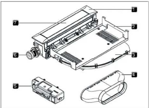
Fig. 3.5 Cooktop extractor PKA3/PKA3AB
[1] Cover frame
[2] Holding plate
[3] Curved duct piece
[4] Straight duct piece
[5] Universal control unit
[6] Control knob
[7] Cover flap
Cooktop extractor system PKAS3/PKAS3AB
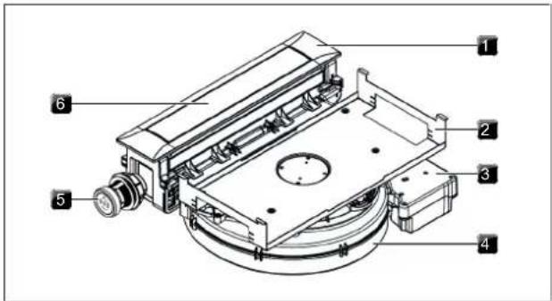
Fig. 3.6 Cooktop extractor system PKAS3/PKAS3AB
[1] Cover frame
[2] Holding plate
[3] Control unit
[4] Fan housing with fan
[5] Control knob
[6] Cover flap
Grease filter components
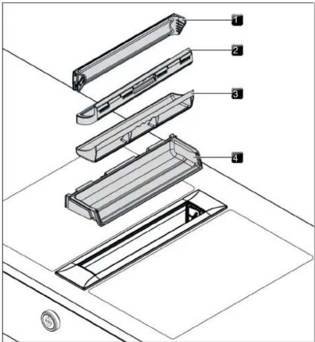
Fig. 3.7 Filter components
[1] Cover flap
[2] Stainless steel grease filter
[3] Filter tray
[4] Maintenance tray
3.3.4 Sensors
The cooktop extractor is equipped with sensors in the area of the cover flap and the grease filter.
Cover flap position sensor
The cover flap sensor detects the position of the cover flap.
- If the cover flap is closed, the cooktop extractor is deactivated.
- If the cover flap is open, the cooktop extractor can be used.
- If the cover flap has been removed, the cooktop extractor is in cleaning mode (cleaning function active) and cannot be used.
Grease filter position sensor
The grease filter sensor detects whether the grease filter has been fitted correctly. If the grease filter is missing or has been fitted incorrectly, the cooktop extractor is deactivated.
If the grease filter is removed, for example, for cleaning, the cover flap can still be closed.
3.3.5 Interface for external devices
The internal interface can be used for extended control options. This has a Home In and a Home Out contact (see the Installation chapter).
- The Home-In contact can be used for the signal input from external switch devices (e.g. window contact switch).
- The Home Out contact can be used to control external installations.
3.3.6 USB port for servicing
The system has a USB port. This port is only suitable for mass storage devices (USB sticks). These USB sticks must be formatted with the FAT32 data system.
The USB port is only designed for updates or data export and only has sufficient power supply for these processes. It is not possible to charge devices or carry out other functions.
3.4 Cooktop appliance description
3.4.1 Display and symbols
The power levels and cooking functions of each cooking zone are shown in the control knob display on the corresponding control knob. The cooktops PKFI3 and PKI3 also have a 7-segment cooktop display for each cooking zone. Power levels and operating functions respectively are shown directly on the cooktop.
| Control knob display Meaning | |
| 0 | Appliance is switched off |
| 1-9 | Power levels |
| P | Power setting |
| 80-250 | Temperature indicator on Tepan stainless steel grill (PKT3) |
| H | Residual heat indicator |
| L | Child lock |
| e.g. 3 5 | Bridging function active (only on PKFI3 and PKT3) |
| U | Pan size recognition (only on PKFI3, PKI3, PKIW3) |
| e.g. 5/5=5= | Rings active (only on PKC3, PKCB3, PKCH3) |
| _0/==u==u | Heat retention level active (not on PKT3) |
| Short-time timer/cooking zone timer active (not on PKT3) | |
| A | Automatic heat up function (not on PKT3) |
| e.g. AS | Automatic heat up function active (not on PKT3) |
| Cleaning function active (only on PKT3) | |
| E | Error message (see "8 Troubleshooting") |
Tab. 3.4 Operating panel display
3.4.2 Layout and size of the cooking zones
Cooktop PKFI3
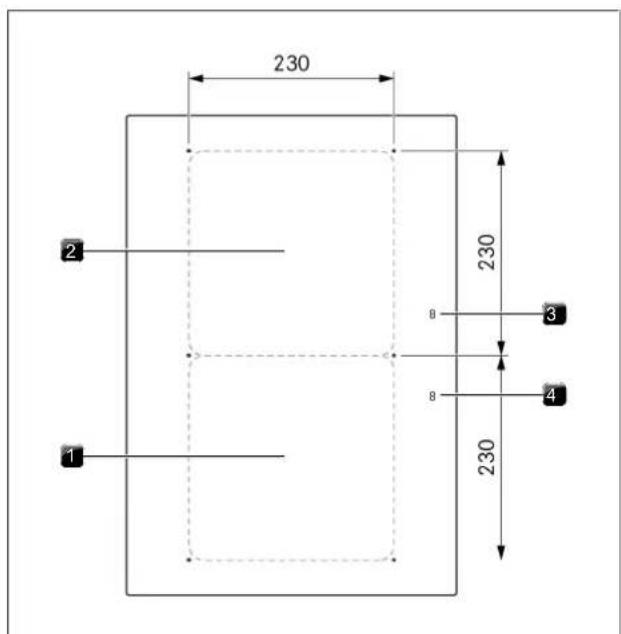
Fig. 3.8 Layout of cooktop PKFI3 and cooking zone dimensions
[1] Front surface induction cooking zone
[2] Rear surface induction cooking zone.
[3] Rear cooking zone display
[4] Front cooking zone display
Cooktop PKI3
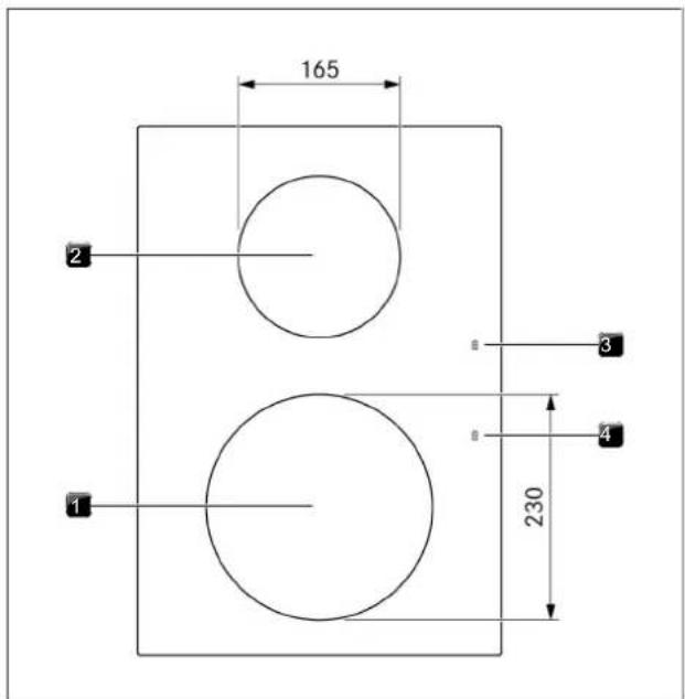
Fig. 3.9 Layout of cooktop PKI3 and cooking zone dimensions
[1] Front induction cooking zone
[2] Rear induction cooking zone
[3] Rear cooking zone display
[4] Front cooking zone display
Cooktop PKIW3
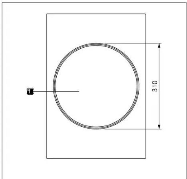
Fig. 3.10 Layout of cooktop PKIW3 and cooking zone dimensions
[1] Induction cooking zone
Cooktop PKC3
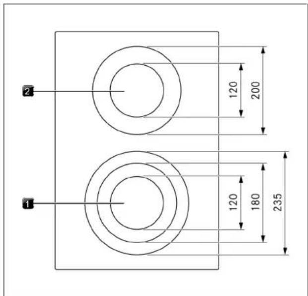
Fig. 3.11 Layout of cooktop PKC3 and cooking zone dimensions
[1] 3-ring front cooking zone
[2] 2-ring rear cooking zone
Cooktop PKCB3
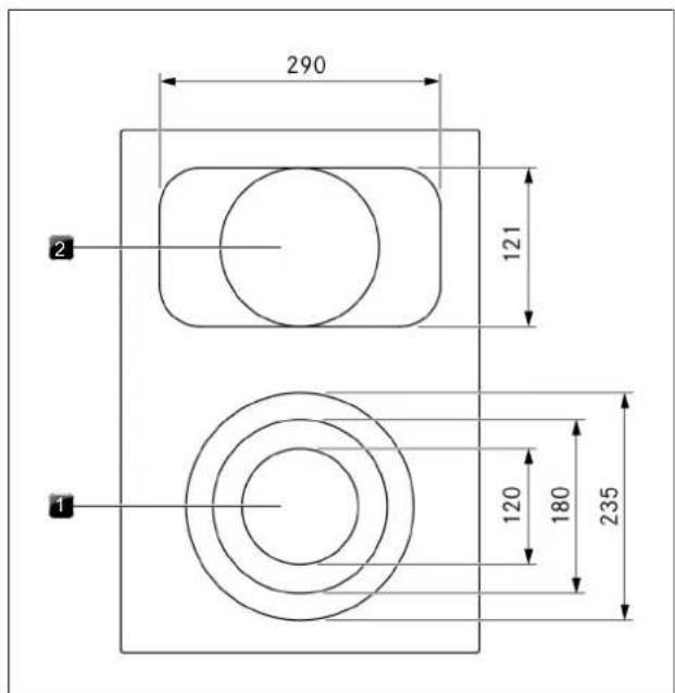
Fig. 3.12 Layout of cooktop PKCB3 and cooking zone dimensions
[1] 3-ring front cooking zone
[2] 2-ring roaster rear cooking zone
Cooktop PKCH3
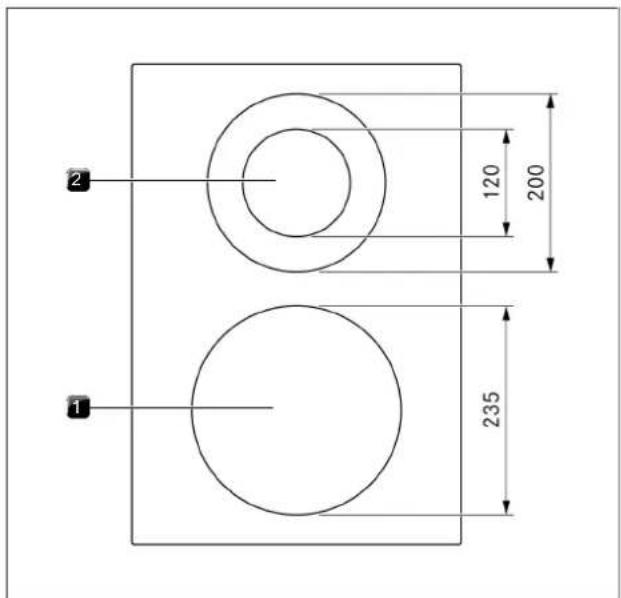
Fig. 3.13 Layout of cooktop PKCH3 and cooking zone dimensions
[1] 1-ring Hyper front cooking zone
[2] 2-ring rear cooking zone
Tepan stainless steel grill PKT3
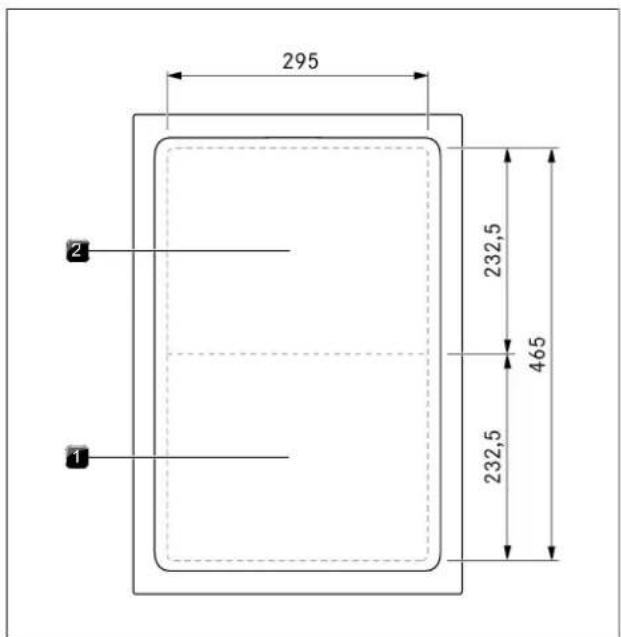
Fig. 3.14 Layout of Tepan stainless steel grill PKT3 and cooking zone dimensions
[1] Front grilling zone
[2] Rear grilling zone
Gas cooktop PKG3
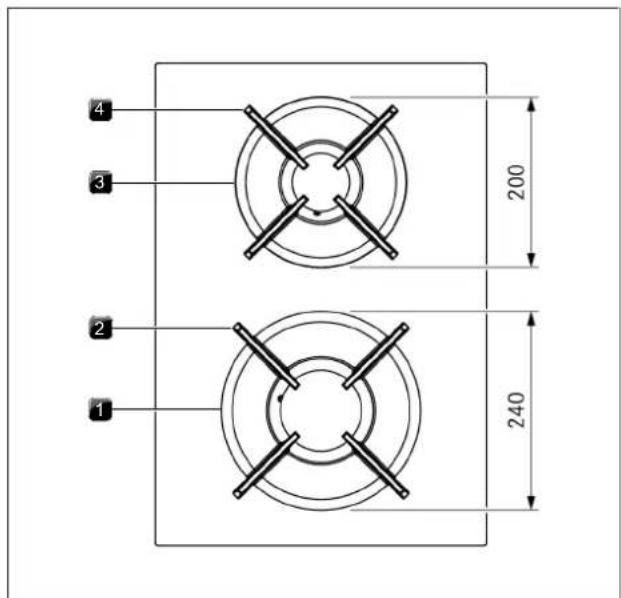
Fig. 3.15 Layout of gas cooktop PKG3 and cooking zone dimensions
[1] High-power front burner
[2] Front pan support
[3] Normal back burner
[4] Rear pan support
3.4.3 How the induction cooktops work
An induction coil is located underneath an induction cooking zone. If the cooking zone is switched on, this coil creates a magnetic field that acts directly on the base of the pot thus heating it up. The cooking zone is only indirectly heated up by the heat emitted by the pot. Cooking zones with induction only work if the cookware has a magnetisable base.
Induction automatically takes into account the size of the cookware used which means that only the area in the cooking zone covered by the base of the pot is heated up.
▶ Observe the minimum pot base diameter.
Power levels
The high power output of induction cooktops results in the very quick heating up of cookware. In order to avoid burning food, slight adjustment is needed in comparison to conventional cooking systems when selecting the power level.
| Activity Power level | |
| Melting butter and chocolate, breaking up gelatine | 1 |
| Keeping sauces and soups warm, soaking rice | 1-3 |
| Cooking potatoes, pasta, soups and ragouts,steaming fruit, vegetables and fish, defrosting food | 2-6 |
| Frying in coated pans, moderate frying (withoutoverheating the fat) of pork cutlets or fish | 6-7 |
| Heating up fat, browning meat, cooking thickenedsauces and soups, making omelettes | 7-8 |
| Cooking large amounts of liquids, grilling steaksand heating water | 9 |
| Heating up water | P |
Tab. 3.5 Recommendations for power levels
The specifications provided in the table are standard values. Depending on the cookware and filling quantity, it is recommended to either decrease or increase the power level.
The heating and heat-through times for the cookware base, as well as the cooking results, are significantly influenced by the structure and material of the cookware.
Suitable cookware
Cookware with this symbol is suitable for induction cooktops. The cookware used for the induction cooktop must be made of metal, feature magnetic properties and possess an ample base.
Suitable cookware is made of:
• stainless steel with a magnetisable base
- enamelled steel
- cast iron
| Appliance Cooking zone Minimum cookware | |
| base diameter | |
| PKI3 Front 120 mm | |
| Back 90 mm | |
| PKFI3 Front 120 mm | |
| Back 120 mm | |
| PKIW3 Wok 210 mm | |
Tab. 3.6 Minimum cookware diameter
▶ Perform a magnet test, if necessary. If a magnet sticks to the base of the utensils, they are normally induction compatible.
Pay attention to the cookware base. The base of the cookware should not show any sign of curvature (exception: wok cooktops). Due to incorrect hob temperature monitoring, this curvature may cause the cookware to overheat. To avoid scratching the cooktop, the base of the cookware must not have any sharp grooves or sharp edges.
▶ Place the cookware (without a mat or similar) directly onto the glass ceramic.
The induction wok (HIW1) is ideal for the Induction wok cooktop and is available as an accessory.
Noises
The following noises may occur in the cookware when using induction cooking zones, depending on the material and the finish of the base:
● Humming may occur when using a high power level. This decreases or disappears when the power level is decreased.
- Crackling or whistling may occur due to cookware bases being made of different materials (e.g. sandwich base).
- Clicking sounds may occur during electronic switching procedures, especially at low power levels.
- Whirring may occur when the cooling fan is switched on. In order to increase the service life of the electronic system, the cooktop is equipped with a cooling fan. The cooling fan switches on automatically if the cooktop is used intensively. You will hear a whirring sound. The cooling fan may continue to run after the appliance has been switched off.
3.4.4 How the Hyper and HiLight cooktops work
Under the cooking zone is a radiant heating element with a heating tape. When the cooking zone is switched on, the heating tape generates radiant heat, which radiates to the cooking zone and heats it up.
Power levels
| Activity Power level | |
| Melting butter and chocolate, breaking up gelatine | 1 |
| Keeping sauces and soups warm, soaking rice | 1-3 |
| Cooking potatoes, pasta, soups and ragouts,steaming fruit, vegetables and fish, defrosting food | 2-6 |
| Frying in coated pans, moderate frying (withoutoverheating the fat) of pork cutlets or fish | 6-7 |
| Heating up fat, browning meat, cooking thickenedsauses and soups, making omelettes | 7-8 |
| Cooking large amounts of liquids, grilling steaksand heating water | 9 |
| Heating up water | P |
Tab. 3.7 Recommendations for power levels
The specifications provided in the table are standard values. Depending on the cookware and filling quantity, it is recommended to either decrease or increase the power level.
The heating and heat-through times for the cookware base, as well as the cooking results, are significantly influenced by the structure and material of the cookware.
Power setting on the Hyper cooktop
The front cooking zone on the Hyper glass ceramic cooktop is fitted with a temporary power setting.
T is P displayed.
The power setting can be used in order to quickly heat up large quantities of water. If the power setting is activated, the cooking zones will run at extra high power. After 10 minutes, the cooking zone automatically switches back to power level 9.
Suitable cookware
Cookware with this symbol is suitable for radiant heating elements. The cookware used for radiant heating surfaces must be metal and have good heat conducting properties.
Suitable cookware is made of:
T stainless steel, copper or aluminium
T enamelled steel
T cast iron
Pay attention to the cookware base. The bottom of the cookware should not show any sign of curvature. Due to incorrect hob temperature monitoring, this curvature may cause the cookware to overheat. To avoid scratching the cooktop, the base of the cookware must not have any sharp grooves or sharp edges.
▶ Place the cookware (without a mat or similar) directly onto the glass ceramic.
3.4.5 How the Tepan stainless steel grill works
Under each grilling zone there is a heating element. When a grilling zone is switched on, the heating element generates heat that directly heats the grill surface.
Power levels and temperature ranges
The power is adjusted via temperature ranges that are shown in the operating panel display in ^ C (temperature indicator).
| Temperature in °C Meaning | |
| C (= 70°C) | Cleaning temperature |
| 80 - 230 | Power levels (in 10°C increments) |
| 240 - 250 | Power setting |
Tab. 3.8 The temperatures corresponding to the power levels
The power output of the Tepan stainless steel grill heats food extremely quickly. A slight adjustment is needed in comparison to conventional cooking systems when selecting the temperature in order to avoid burning food.
| Activity Temperature in °C | |
| Steaming fruit, e.g. apple slices, peach halves, banana slices | 160 - 170 |
| Browning chopped vegetables, fried eggs, veal, poultry | 180 - 190 |
| Browning breaded or battered fish, pancakes, sausages, pork, lamb | 190 - 200 |
| Browning potato fritters, prawns, corn on the cob and escalopes | 200 - 210 |
| Fast browning beef, fish, meatballs | 220 - 230 |
| Browning steaks | 250 (Power setting) |
Tab. 3.9 Temperature recommendations (the specifications provided in the table are standard values)
3.4.6 How the gas cooktop works
If a cooking zone is switched on, the flame generates heat, which directly heats the base of the cookware. The gas flame is controlled by a highly accurate electronic gas control system (e-gas system). Among other things, servomotors are used to accurately control each gas burner. These servomotors calibrate themselves from time to time and typical humming noises can be heard that are totally normal and do not constitute a malfunction. The advantage of this electronic gas control system is the optimum, repeatable heat regulation, which means that the selected power levels are identical in every cooking session. In addition, a clean, constantly increasing flame is formed at every power level. Furthermore, if necessary, it can be automatically reignited.
The cooktop has automatic ignition.
Power levels
The power is adjusted using power levels 1 - 9 and P. The output of gas cooktops means that food is heated quickly. In order to avoid burning food, slight adjustment is needed in comparison to conventional cooking systems when selecting the power level.
| Activity Power level | |
| Keeping cooked meals warm | 1-2 |
| Browning chopped vegetables, fried eggs, veal, poultry | 3-5 |
| Grilling prawns, corn on the cob, schnitzel, beef, fish or burgers | 5-7 |
| Bringing large amounts of liquid to the boil, searing steaks | 8-9 |
| Heating up water | P |
Tab. 3.10 Recommendations for power levels
The specifications provided in the table are standard values.
Each gas cooking zone is equipped with a safety thermocouple. This element detects if the flame has gone out (e.g. if a pan has boiled over or there is a strong draught). The gas supply is then turned off and the burner is automatically reignited. If reignition is not possible, the gas supply is stopped. A gas leak is therefore prevented.
Suitable cookware
Cookware with this symbol is suitable for gas cooktops.
Suitable cookware is made of:
• copper
- stainless steel
- aluminium
- cast iron
Adhere to the dimensions in the table:
| Burner Minimum pan diameters | Recommended pan diameter |
| Normal burner 120 mm 140–200 mm | |
| High-power burner 160 mm 180–240 mm |
Tab. 3.11 Pan diameters
The heating and heat-through times for the cookware base, as well as the cooking results, are significantly influenced by the structure and material of the cookware. Cookware with a thick base ensures more even heat distribution. In the case of a thin base there is a risk of the food becoming overheated in places. The cooktop may also become damaged.
Take special care not to overheat the cookware as the base can become deformed. For this reason, you should never heat up cookware when empty.
Cookware with an uneven base may tip over. A slight wobble can never be completely ruled out.
Only use cookware with a diameter that is within the given dimensions. If the diameter is too large, the hot gases flowing outwards from under the base may damage the worktop or any non-heat-resistant wall, e.g. with panelling, as well as part of the cooktop and the cooktop extractor. Bora shall not be held liable for any such damage.
3.5 Safety features
3.5.1 Anti-trap protection
The electrical cover flap on the cooktop extractor has anti-trap protection. If the cover flap is obstructed when opening or closing, it automatically stops moving. The cover flap returns to the starting position and tries again. If the anti-trap protection triggers again, the error message appears on the control knob (see "8 Troubleshooting").
3.5.2 Safety shut-down
If an appliance is switched on but is not used for a predefined time, it is automatically switched off.
Cooktop extractor
The cooktop extractor is automatically switched off after an operating time of 120 minutes without any change to the power level.
Cooktops
Each cooking zone is switched off automatically when the cooking zone exceeds the maximum operating duration on one power level or heat retention level. is also displayed (residual heat indicator).
▶ Switch the appliance back on if you wish to use it again after safety shut-down.
Safety shut-down on the different power levels
| Power levels Safety shut-down after hours:minutes | ||
| PKFI3, PKI3, PKIW3, PKG3 | PKC3, PKCB3, PKCH3 | |
| 1 | 8:24 6:00 | |
| 2 | 6:24 6:00 | |
| 3 | 5:12 5:00 | |
| 4 | 4:12 5:00 | |
| 5 | 3:18 4:00 | |
| 6 | 2:12 1:30 | |
| 7 | 2:12 1:30 | |
| 8 | 1:48 1:30 | |
| 9 | 1:18 1:30 | |
Tab. 3.12 Safety shut-down on the different power levels
After 10 minutes (20 minutes on PKG3), the power setting is automatically switched back to power level 9.
Safety shut-down on the different power levels
| Power levels Safety shut-down after hours:minutes | |
| PKT | |
| 150 | 8:24 |
| 160 | 6:24 |
| 170 | 5:12 |
| 180 | 4:12 |
| 190 | 3:18 |
| 200 | 2:12 |
| 210 | 2:12 |
| 220 | 1:48 |
| 230 | 1:18 |
Tab. 3.13 Safety shut-down in the different temperature ranges
After 10 minutes, the power setting automatically reverts to 230^ C.
| PKFI3, PKI3, PKIW3, PKG3, PKC3, PKCB3, PKCH3: | |
| heat retention level Switch off after hours:minutes | |
| 1 (±) | 8:00 |
| 2 (±) | 8:00 |
| 3 (±) | 8:00 |
| 80-140°C (PKT) 8:00 | |
Tab. 3.14 Safety shut-down on the different heat retention levels
3.5.3 Residual heat indicator
If a cooking or grilling zone is still hot after switching off, there is a risk of burns or fire. While His displayed (residual heat indicator), do not touch the cooking or grilling zone or place any heat-sensitive objects on top of it. After a sufficient cooling period the indicator will go out.
| Cooktops Tepan stainless steel grill |
| Limit temperature < 60°C < 50 °C |
Tab. 3.15 Residual heat indicator limit temperatures
3.5.4 Overheating protection
The appliance is fitted with overheating protection. The overheating protection can be triggered if:
• cookware is heated up empty;
- oil or fat is heated on high power;
- a hot cooking zone is switched on again after a power cut.
Whilst the overheating protection is active, one of the following steps is taken:
- the activated power setting is switched back to the previous level;
- the power setting can no longer be switched on;
• the set power level is reduced;
● the cooktop switches off completely.
After a sufficient cooling period, the cooktop can be used again in full.
3.5.5 Child lock
The child lock prevents the appliance from being switched on accidentally.
▶ is Ldisplayed.
If a single cooktop is operated without a cooktop extractor, removal of the knob ring can prevent the appliance from being switched on accidentally or without permission.
4 Overview of features and functions
The full range of functions is only available for Professional 3.0 system cooktops in combination with the cooktop extractors.
| BORA Professional 3.0 system Cooktop extractors Cooktops | |||||||||||||||
| Appliance features PKA3 | PKAS3 | PKFI3 PKI3 PKIW3 PKC3 PKCB3 PKCH3 PKT3 PKG3 | |||||||||||||
| PKA3AB | PKAS3AB | ||||||||||||||
| Electronic power adjustment √ | √ | √ | √ | √ | √ | √ | √ | √ | √ | ||||||
| Power level display √ | √ | √ | √ | √ | √ | √ | √ | √ | |||||||
| Interface communication √ | √ | ||||||||||||||
| Electrical cover flap with position sensor √ | √ | ||||||||||||||
| Stainless steel grease filter | √ | √ | |||||||||||||
| Grease filter position sensor | √ | √ | |||||||||||||
| USB port for servicing | √ | √ | |||||||||||||
| Pan size recognition | √ | √ | √ | ||||||||||||
| Cooktop display | √ | √ | |||||||||||||
| Temperature display | √ | ||||||||||||||
| System functions | |||||||||||||||
| Pause function | √ | √ | √ | √ | √ | √ | √ | √ | √ | √ | |||||
| Additional cooktop extractor functions | |||||||||||||||
| Extractor cleaning function | √ | √ | |||||||||||||
| Short-time timer | √ | √ | |||||||||||||
| Extractor power setting | √ | √ | |||||||||||||
| Automatic extractor function √ | √ | ||||||||||||||
| Filter service display | √ | √ | |||||||||||||
| Automatic after-run | √ | √ | |||||||||||||
| Additional cooktop functions | |||||||||||||||
| Cooktop power setting | √ | √ | √ | √* | √ | ||||||||||
| Cooking zone timer | √ | √ | √ | √ | √ | √ | |||||||||
| Automatic heat up function | √ | √ | √ | √ | √ | √ | |||||||||
| Variable heat retention function | √ | √ | √ | √ | √ | ||||||||||
| Pan size recognition | √ | √ | √ | ||||||||||||
| Additional ring switching (2-ring additional switching) | √** | √** | √** | ||||||||||||
| Additional ring switching (3-ring additional switching) | √* | √* | |||||||||||||
| Bridging function | √ | √ | |||||||||||||
| Cleaning function | √ | ||||||||||||||
| Safety features | |||||||||||||||
| Child lock | √ | √ | √ | √ | √ | √ | √ | √ | √ | ||||||
| Safety shut-down | √ | √ | √ | √ | √ | √ | √ | √ | √ | ||||||
| Anti-trap protection | √ | √ | |||||||||||||
| Active error monitoring | √ | √ | √ | √ | √ | √ | √ | √ | √ | ||||||
| Residual heat indicator | √ | √ | √ | √ | √ | √ | √ | ||||||||
| Overheating protection | √ | √ | √ | √ | √ | √ | √ | ||||||||
Tab. 4.1 Function overview
*only on the front cooking zone
**only on the rear cooking zone
How it works and its functions are described in more detail in the "Functions and operation" chapter.
5 Functions and operation
▶ Observe all safety and warning information (see "2 Safety").
5.1 Knob operation
5.1.1 Operating the knob ring
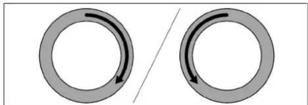
The ring on the control knob can be turned both clockwise and anticlockwise. It can be turned as far as you wish; there is no defined 0 position.
Turn it clockwise (to the right) to:
- Switching on
- increase power level/value
- navigate the menu
Turn it anticlockwise (to the left) to:
- Switching off
• decrease power level/value - navigate the menu
natural_image
Two circular diagrams with curved arrows indicating rotational or directional motion, separated by a diagonal line (no text or symbols)Fig. 5.1 Operating the knob ring
5.1.2 Operating the touch surface
The touch surface of the control knob reacts to different touch commands:
Command Contact Time
Tap brief touch < 1 s
Double tap 2 brief taps one after the other
Long press keep finger in place longer 2-4 s
Extra-long press keep finger in place longer 5-8 s
Tab. 5.1 Operating the touch surface
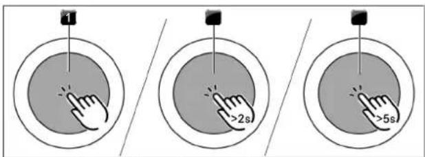
Fig. 5.2 Diagram of the touch commands
[1] Tap command diagram
[2] Long press diagram
[3] Extra-long press diagram
Use tap commands to:
- Calling up the function menu
- confirm menu items/times/functions
Use double-tap commands to:
- Pause function
Use long-press commands to:
- Deactivating the childproofing feature
- Exiting the additional function menu and configuration menu
Use extra-long-press commands to:
- reset the filter service life
- Accessing the configuration menu
5.2 Switching the system on and off
5.2.1 Switching on
▶ Turn a knob ring of your choice clockwise
• The system is activated.
- is displayed on all displayed.
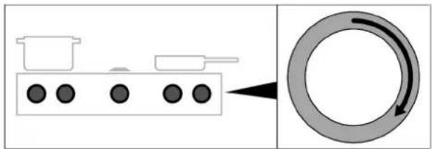
natural_image
Diagram showing a cooking setup with pots and a circular ring with directional arrows (no text or symbols)Fig. 5.3 Switching on the system
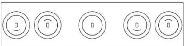
natural_image
Five circular icons with curved and straight lines, each containing a small icon (no text or symbols)Fig. 5.4 Standard display after switching on
If L is displayed on all control knobs when the appliance is switched on, the child lock is active. The appliance cannot be operated until this is deactivated.
5.2.2 Switching off
▶ Turn the knob ring anticlockwise to power level 0.
- Any active additional functions will be deactivated and the appliance will be switched off.
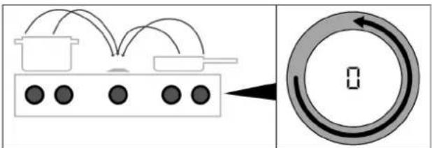
Fig. 5.5 Switching the appliances off
- If all connected appliances are switched off (= power level 0), the whole system is automatically switched off after 10 seconds.
The cooktop extractor was switched on
- The automatic after-run function is started.
- As soon as the after-run period is complete, the appliance is automatically switched off.
● The display switches off after 10 seconds.
The cooktop was switched on
- is shown in the control knob display for previously active and still hot cooking zones displayed (residual heat indicator).
- If there is no longer any residual heat, the display will switch off after 10 seconds.
5.3 Operating the cooktop extractor
5.3.1 General operating instructions for the cooktop extractor
Both cooktop extractor functions and system functions can be operated using the cooktop extractor control knob.
The cooktop extractor must only be operated with BORA cooktops.
The cooktop extractor must only be operated when the grease filter components are installed.
Recommendations for efficient vapour extraction
In the case of tall cooking pots, place the lid on at an angle so that the cooking vapours are guided towards the cooktop extractor.
▶ Only operate the cooktop extractor at the minimum power level required for effective vapour extraction. This enables you to improve the performance of the odour filters in recirculation mode.
▶ Only operate the hob at the minimum power level required for cooking. This reduces the cooking vapours and the power consumption.
▶ Avoid strong drafts.
Restricted functions when using the cooktops without a cooktop extractor
If cooktops are installed and operated without a cooktop extractor, only limited functions will be available. The following functions will not be available:
- System functions
- Pause function
- Short-time timer
- Child lock
- All settings/functions in the configuration menu
5.3.2 Setting the fan power level
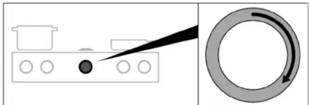
The power levels are controlled by turning the knob ring to the desired power level (electronic power adjustment).
Increasing the power level
▶ Turning the knob ring clockwise
Reducing the power level
▶ Turning the knob ring anticlockwise
- The selected power level is shown in the display on the extractor control knob.
natural_image
Diagram showing a kitchen appliance with a pointer and a circular motion arrow (no text or symbols)Fig. 5.6 Setting the fan power level
5.3.3 Fan power setting
Activating the power setting
▶ When the power setting is activated, maximum extractor power is available for a predefined time.
- This power setting makes it possible to suction away high levels of cooking vapours more quickly.
- After 10 minutes, the power setting is automatically switched back to power level 9.
Deactivating the fan power setting
The fan power setting is deactivated early if another power level is set.
5.3.4 Automatic after-run
When the extractor is switched off, the automatic after-run function is activated. The cooktop extractor continues to run at a lower level and switches off automatically after 20 minutes. The display switches off 10 seconds later.
Switching off the automatic after-run early
▶ touching the touch surface of the control knob or
▶ turning the knob ring anticlockwise
- The after-run function will be switched off early and the display will go out after 10 seconds.
BORA expressly recommends use of the cooktop extractor after-run function.
5.4 Cooktop extractor function menu
Every appliance offers different additional functions. These can be selected and activated via a function menu. Only the functions available for each type of appliance are shown in the corresponding function menu. The cooktop extractor function menu contains both system functions and cooktop extractor functions.
There is a total of 5 additional functions to choose from:
| Menu item Function System | function | Cooktop extractor function | |
| IC | Extractor cleaning √ | ||
| 2E | Short-time timer √ | ||
| 3A | Automatic extractor function | √ | |
| 4L | Child lock √ | ||
| 5F | Show and reset filter status | √ | |
Tab. 5.2 Overview of cooktop extractor function menu
Calling up the function menu
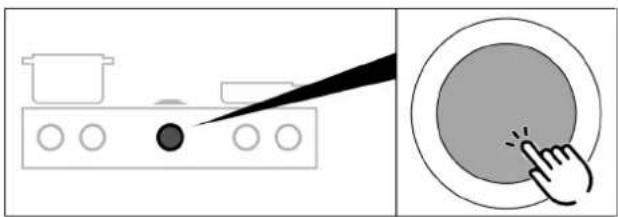
▶ Touch the cooktop extractor control knob
• The function menu is opened.
- The first menu item is shown in the control knob display.
natural_image
Illustration showing a kitchen appliance with a pointer and a circular button, no text or symbols presentFig. 5.7 Calling up the cooktop extractor function menu
5.4.1 Cooktop extractor cleaning function
The cooktop extractor cleaning function enables components to be removed easily and safely.
Activating the cooktop extractor cleaning function If the grease filter is removed from the cooktop extractor during operation, the error message 'FF out' is displayed or 'E013' if the cover flap is removed. If this is acknowledged by a short touch, the system automatically switches to using the cleaning function.
Manually activating the cooktop extractor's cleaning function
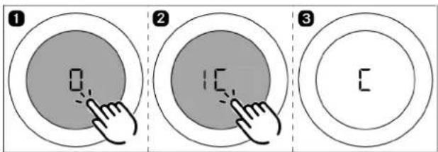
Fig. 5.8 Activating the cooktop extractor cleaning function
- The cleaning function is activated and an acoustic signal is heard.
- The cover flap opens and is shown in the control knob display.
- The fan motor will not start or will switch off if running. If the system is reactivated after the cooktop extractor's cleaning function is started, C will continue to be displayed on the cooktop extractor's control knob. It is still possible to cook but the cooktop extractor remains inactive and cannot be used. Only once the grease filter and cover flap have been refitted can the cooktop extractor be reactivated.
Closing the cover flap to start a cooking session
▶ Touch the cooktop extractor control knob
- The cover flap closes (without grease filter) and displayed.
- It is possible to cook, however, the cooktop extractor cannot be operated.
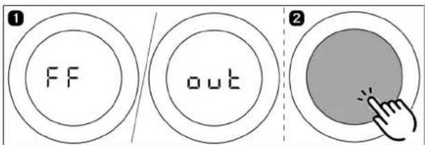
Fig. 5.9 Closing the cover flap to start a cooking session
Deactivating the cooktop extractor cleaning function
Correctly insert the filter tray, grease filter and cover flap into the opening in the extractor (see "7 Cleaning and maintenance").
Tap or twist the cooktop extractor's control knob.
• The cover flap closes.
• The cleaning function deactivates.
- The cooktop extractor and all of its functions can be used again.
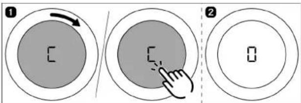
Fig. 5.10 Deactivating the cooktop extractor cleaning function
5.4.2 Short-time timer
The short-time timer emits both a visual and an acoustic signal after a time set by the user and provides the function of a conventional egg timer.
| Function Times that can be set in minutes | |
| Short-time timer 0-120 | (0:30, 1, 1:30, 2, ... 9, 9:30, 10, 11,...19, 20, 25, 30 ...115, 120) |
Tab. 5.3 Times that can be set on the short-time timer
Activating the short-time timer
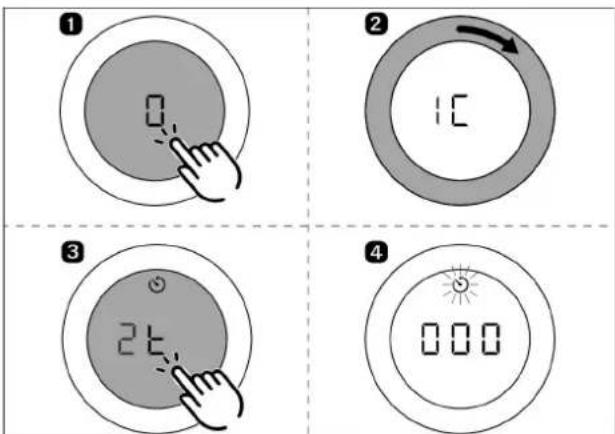
Fig. 5.11 Activating the short-time timer
- The timer icon is displayed.
- The time value appears in the cooktop extractor control knob display.
▶ Set a time. - If no time is set within 4 seconds, the short-time timer is deactivated.
Setting the time and starting the short-time timer
- Turning clockwise increases the time (starting at 0 minutes). Turning anticlockwise reduces the time.
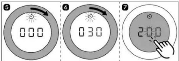
Fig. 5.12 Turning the knob ring clockwise
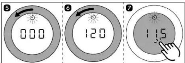
Fig. 5.13 Turning the knob ring anticlockwise
- When set to between 0 and 10 minutes, the time reduces/increases in 30-second increments when the control knob is turned.
- When set to between 10 and 20 minutes, the time reduces/increases in 1-minute increments when the control knob is turned. Otherwise, it increases/decreases in 5-minute increments.
- After confirming with a touch command, an acoustic signal is heard, the short-time timer is activated and the set time starts to count down.
- The current power level and remaining time are shown alternately in the control knob display.
- The current time remaining is shown to the minute when more than 10 minutes remain, to 30 second increments when less than 10 minutes remain, and to the second when only 2 minutes remain.
Time lapsed
When the set time has elapsed, an acoustic signal sounds for 1 minute and the timer displayed on the control knob counts down as a negative.
The flashing and the acoustic signal can be stopped by pressing the touch surface.
Switching off the short-time timer early
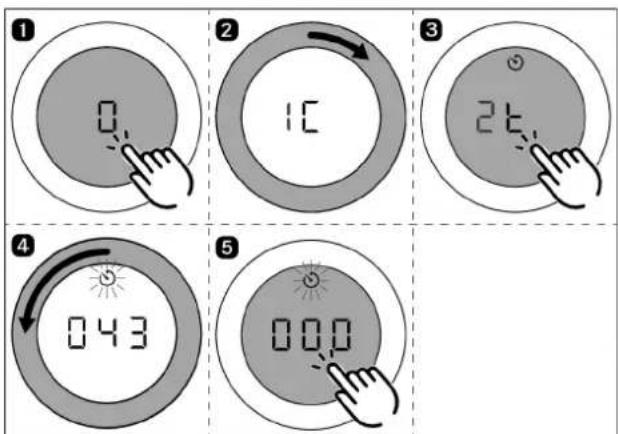
Fig. 5.14 Switching off the short-time timer early
- The short-time timer is deactivated early and an acoustic signal is heard.
5.4.3 Automatic extractor function
The extractor power level automatically adjusts itself depending on the current cooktop settings. No manual adjustment of the fan controls is necessary but it is possible.
| Cooktop power levels Temperature PKT3 Cooktop extractorpower level |
| Heat retention level 1 - 2 |
| U |
| Heat retention level 2 - 4 |
| U |
| Heat retention level 3 - 7 |
| U |
| 1 70-80 2 |
| 2 90-160 3 |
| 3 170 4 |
| 4 180 5 |
| 5 190 6 |
| 6 200 7 |
| 7 210 8 |
| 8 220 9 |
| 9 230 9 |
| P 240/250 P |
Tab. 5.4 Cooking levels and assigned extractor power level when the automatic extractor function is active
If the power level of a cooking zone is changed, the automatic extractor function automatically adjusts the extractor power level after a time delay of...
• ...10 seconds (cooktops PKFI3, PKI3, PKIW3).
• ...20 seconds (cooktops PKC3, PKCB3, PKCH3, PKT3)
Activating the automatic extractor function
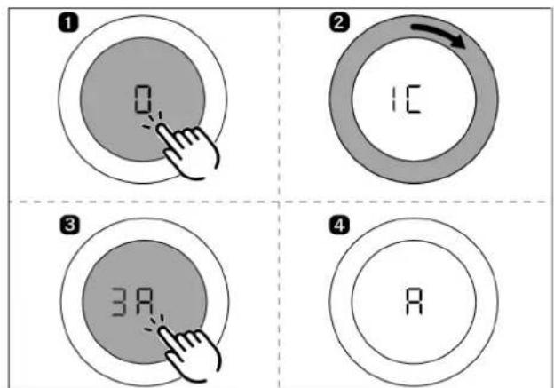
Fig. 5.15 Activating the automatic extractor function
• The automatic extractor function is activated.
- is shown in the control knob displayed.
If the power level is changed on one of the connected cooktops, the extractor power level is automatically adjusted after a slight delay. If all connected cooking zones are switched off or paused, the automatic after-run function will start after a slight delay.
The automatic extractor function is permanently activated and remains active each time the system is started up until it is deactivated.
Deactivating the automatic extractor function
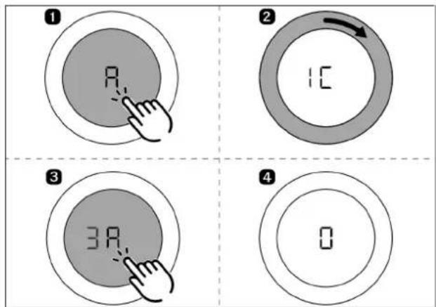
Fig. 5.16 Deactivating the automatic extractor function
- The automatic extractor function is deactivated.
- is shown in the control knob displayed.
5.4.4 Child lock
The child lock prevents the appliance from being switched on accidentally.
Permanently activating the child lock
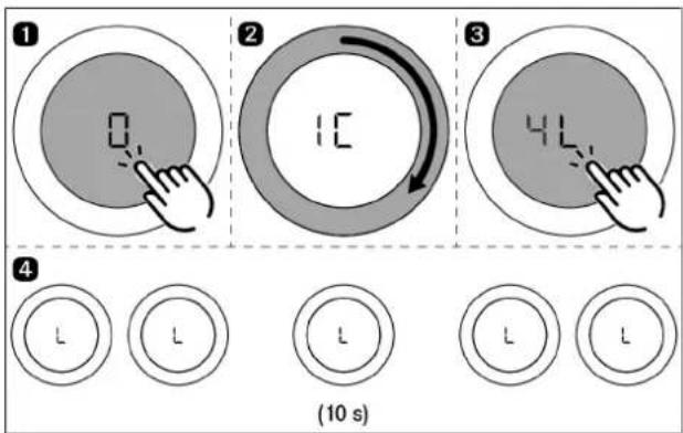
Fig. 5.17 Permanently activating the child lock
- All appliances must be inactive (or is displayed on all control knobs).
- While appliances are active, the menu item 4L cannot be selected.
- is displayed on all Ldisplayed.
- The display switches off after 10 seconds.
Deactivating the child lock for a cooking session
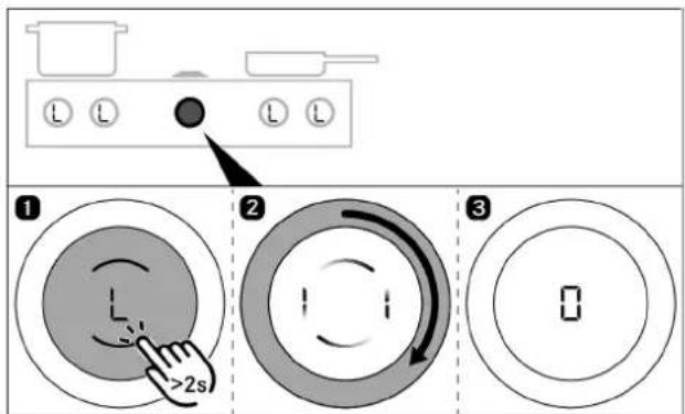
Fig. 5.18 Deactivating the child lock for a cooking session
- The child lock is deactivated for a cooking session and the system is unlocked.
- is displayed on all displayed.
Permanently deactivating the child lock
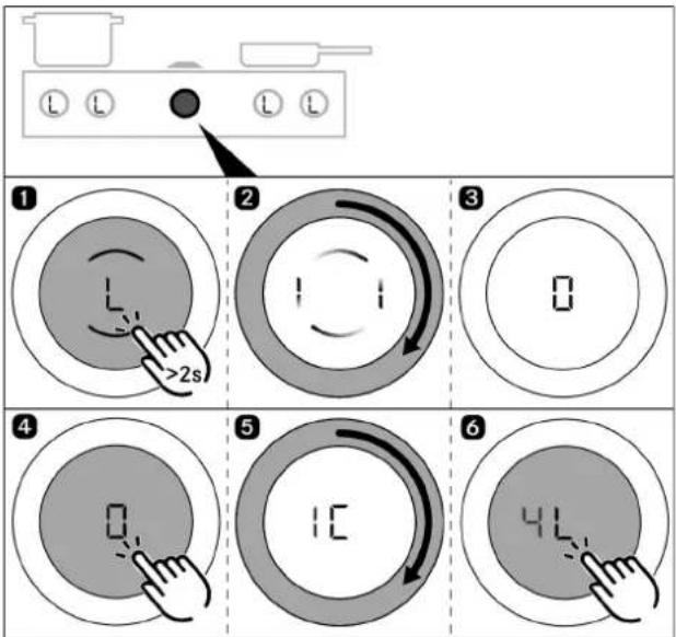
▶ Repeat steps 1 to 3 under “Deactivating the child lock for a cooking session”
▶ Open the cooktop extractor function menu.
▶ Repeat steps 1 to 3 under “Permanently activating the child lock”.
- The child lock is permanently deactivated.
- is displayed on all displayed.
• The display switches off after 10 seconds.
flowchart
graph TD
    A["Start"] --> B{Step 1}
    B -->|Close| C["Arrow to L"]
    C --> D["Step 2"]
    D --> E["Arrow to >2s"]
    E --> F["Step 3"]
    F --> G["Arrow to 0"]
    G --> H["Step 4"]
    H --> I["Arrow to 0"]
    I --> J["Step 5"]
    J --> K["Arrow to 1C"]
    K --> L["Step 6"]
    L --> M["Arrow to 4L"]
Fig. 5.19 Permanently deactivating the child lock
5.4.5 Filter service life and filter service display
The maximum service life of the recirculation filter is defined by the filter type configured in the system (filter service life). Depending on the type of filter fitted, the filter service display will be activated after 300 or 600 operating hours. If an 'F' (filter service display) appears on the control knob display after switching on the cooktop extractor, the recirculation filter's service life has come to an end and the filter needs to be replaced (filter change).
- The filter service display is shown every time the cooktop extractor is switched on and remains active until the filter has been changed and the filter service display has been reset.
- The cooktop extractor can still be operated without limitations.
- To use the cooktop extractor, the filter service display can be deactivated once with a tap or permanently reset.
If the service life of the activated charcoal filter is exceeded, the correct functioning of the system may be affected. It is still possible to use the cooktop extractor, however, the warranty and guarantee claims shall then be invalid. The components of the grease filter require regular cleaning regardless of the filter service display.
Displaying the remaining filter service life
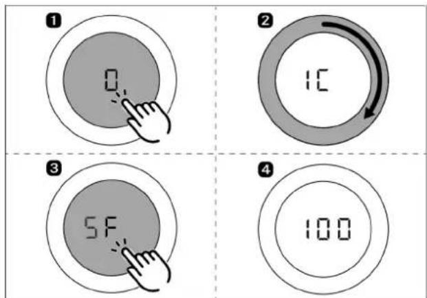
Fig. 5.20 Displaying the remaining filter service life
- The remaining filter service life is shown in hours in the control knob display (e.g. 100 hours).
Resetting the filter service life early
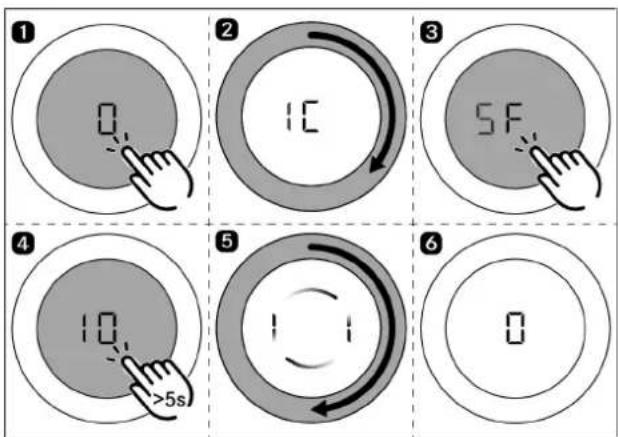
flowchart
graph TD
    A["1: 0"] --> B["2: 1C"]
    B --> C["3: 5F"]
    C --> D["4: 10, >5s"]
    D --> E["5: 1, 1, 1, 1, 1"]
    E --> F["6: 0"]
Fig. 5.21 Resetting the filter service life early
Deactivating the filter service display for a cooking session
The recirculation filter's service life has come to an end. appears on the cooktop extractor's control knob Fdisplayed.
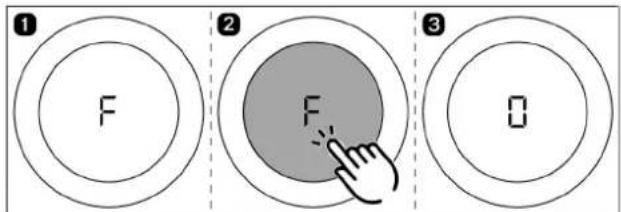
Fig. 5.22 Deactivating the filter service display for a cooking session
- The cooktop extractor can be used for a cooking session.
- is shown in the control knob displayed.
Resetting the filter service display
When the recirculation filter is replaced, the filter service display must be reset.
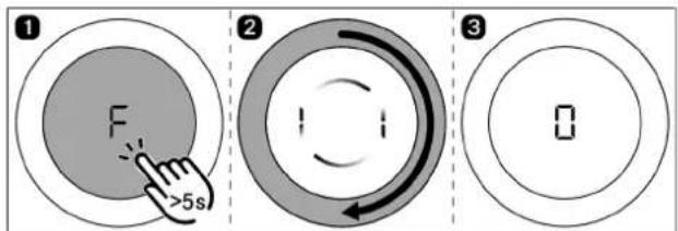
Fig. 5.23 Resetting the filter service display
- The filter service life is reset and the filter service display is deactivated.
• is shown in the control knob displayed.
5.5 Operating the cooktops
The full range of functions is only available for Professional 3.0 system cooktops in combination with the cooktop extractors.
Clean the cooking zone before using the cooktop for the first time (see "7 Cleaning and maintenance").
5.5.1 General operating instructions for cooktops
Cooktops are operated with 2 control knobs. There are 9 power levels, an optional power setting and various functions available for each cooking zone. Each cooking zone has its own control knob; the front cooking zone is operated using the left-hand knob and the rear cooking zone using the right-hand knob.
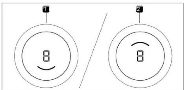
Fig. 5.24 Cooking zone indicator
[1] active front cooking zone
[2] active rear cooking zone
Restricted functions when using the cooktops without a cooktop extractor
If cooktops are installed and operated without a cooktop extractor, only limited functions will be available. The following functions will not be available:
- System functions
- Pause function
- Short-time timer
- Child lock
- All settings/functions in the configuration menu
5.5.2 Special operating instructions for the Tepan stainless steel grill
Initial operation:
▶ Heat the griddle to 220^ C for approx. 25 minutes before using it for the first time (= power level 8 for both grilling zones).
- Bothersome odours may be emitted during this process.
Operating instructions:
▶ Clean the grill surface before using the appliance for the first time (see "7 Cleaning and maintenance").
▶ Preheat the grilling zone for 5 minutes before it is used each time.
- During heating or cooling the griddle may make some noise. This is a normal occurrence.
- A fan is built in to the Tepan stainless steel grill for cooling, guaranteeing a long service life for the electronic components and rapid cooling of the grill surface. Different measures have been taken to keep noise to a minimum, but it cannot be completely avoided.
- During use, the griddle may show signs of curvature.
- During grilling or heating on a high power level, the griddle may adopt a light brown colour.
5.5.3 Special operating instructions for the gas cooktop
When operating the cooktop for the first time or after a prolonged period without use or when the liquid gas bottles have been changed, it is possible that the burner may not ignite. This may be due to air in the gas pipe or the electronic gas regulator may need recalibrating. Follow the initial operation instructions (see "Installation instructions").
In the case of the gas cooktop, due to the use of enamelled cast iron parts, slight colour variations and irregularities are common. Furthermore, flash rust may appear at the support points, which can be easily removed with a damp cloth. These spots are normal and are not considered an impairment.
As a result of use, some of the components of the gas cooktop can become discoloured. This discolouration is normal and does not have a negative effect on the gas flame or the functioning of the cooktop.
When using the gas burner, you may hear gas escaping from it. The burner flame turns orange as a result of prolonged operation and/or impurities on the burner and in the ambient air (dust). These properties are normal and can occur independently of one another.
In the event of smoke or fire while operating the gas cooktop, turn off the gas supply and switch off the appliance at the wall socket.
If you smell gas or have problems with the gas installation, switch off the gas supply. Open the window and ensure good ventilation.
Operating instructions:
The use of a gas cooktop results in the formation of heat and moisture in the area where it is installed. Intensive use of the appliance for a long time may require additional ventilation, e.g. opening a window or more effective ventilation, e.g. operation of the mechanical ventilation device at a higher power level.
▶ Ensure sufficient ventilation.
▶ Keep natural ventilation openings open.
▶ Use a mechanical ventilation device if possible.
▶ Do not put cookware with an uneven base on the pan support.
▶ Never heat empty cookware.
▶ Always place the cookware on the pan support provided. Cookware must not be placed directly on the burner.
▶ Do not use roasters, pans or stone grills that are so large that they cover several burners. The resulting heat accumulation can damage the cooktop.
▶ Ensure that the burner parts and pan supports are positioned correctly.
▶ Do not switch the gas cooktop on until all burner parts are correctly assembled.
▶ Ensure that the burner flame does not protrude from under the base of the cookware and rise up the outside of the pot.
▶ Do not keep any highly flammable objects near the cooktop.
Only use cookware with a diameter that is within the given dimensions. If the diameter is too large, the hot gases and flames flowing outwards from under the base may damage the worktop or any non-heat-resistant surfaces, e.g. walls with panelling, as well as parts of the cooktop and the cooktop extractor. Bora shall not be held liable for any such damage.
Do not use the gas cooktop without cookware for extended periods of time (>5 min) with the cooktop extractor switched on. This results in very high temperatures and may damage the gas cooktop and air-channelling components of the cooktop extractor.
The tips of the flames should remain under the base of the pot. Protruding flame tips emit heat into the air unnecessarily and can damage pan handles and air-channelling components (cooktop extractor) and increase the risk of burns. Furthermore, the outer part of the gas flame is much hotter than the core.
Protect your hands when the appliance is hot by using oven gloves or pot holders. Only use dry gloves or pot holders. Wet or damp fabrics conduct heat more easily and can cause steam burns. Ensure that these fabrics do not get too close to the flames. Do not use oversized pot holders, tea towels or similar.
i Grease splashes and other flammable (food) residues on the cooktop can catch fire. Remove them as soon as possible.
For maximum performance with minimum gas consumption, we recommend that you:
▶ use cookware with a base that covers the flame entirely so that this does not burn beyond the base;
▶ use suitable pans on each gas burner;
▶ position the cookware centrally on the gas hob;
▶ set the gas burner to the lowest power level (small flame) once the pan contents are simmering;
▶ adjust the power level of the cooktop extractor to the power level of the gas cooktop.
Using the gas cooktop with a cooktop extractor:
If the gas cooktop is used together with a cooktop extractor, the airflow of the extractor can affect the gas flame.
▶ Avoid using a high power level on the cooktop extractor when the gas cooktop is set to a low power level.
▶ If necessary, reduce the power level on the cooktop extractor when you turn on the gas cooktop.
▶ Do not use the gas cooktop without cookware. The gas flame is protected from the airflow of the cooktop extractor by the geometry of the pan supports and the cookware.
▶ If necessary, reduce the power level on the cooktop extractor to improve heat input or distribution.
Flames can set fire to or damage the grease filter in the cooktop extractor and the air-channelling components. Never flambé food when using a cooktop extractor.
The performance characteristics of the gas cooktop (e.g. heating times, efficiency, etc.) are affected by the cooktop extractor. The cooktop extractor also affects the heat input and distribution.
In recirculation mode the recirculated air affects the gas cooktop. If the gas flame goes out, is excessively affected by the extractor and/or the flame is not as it should be (e.g. soot production, flame blowback, etc.), the return flow aperture must be enlarged.
5.5.4 Setting cooking zone power levels
The power levels are controlled by turning the knob ring to the desired power level (electronic power adjustment).
Increasing the power level
▶ Turning the knob ring clockwise
Reducing the power level
▶ Turning the knob ring anticlockwise
- The selected power level is shown in the display on the extractor control knob.
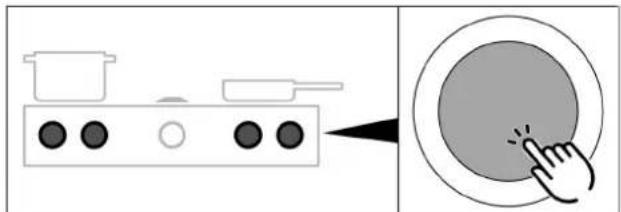
natural_image
Diagram showing a cooking pot with three panes and a button, connected by an arrow to a circular button (no text or symbols)Fig. 5.25 Setting cooking zone power levels
Setting the temperature on the Tepan stainless steel grill
▶ Turn the knob ring to the desired temperature.
- The control knob display shows the target temperature for 3 seconds. Then the warm-up phase begins.
- During the warm-up phase, the corresponding cooking zone display flashes and the current temperature is shown.
- As soon as the target temperature is reached, the warm-up phase comes to an end and the target temperature is continuously displayed.
5.5.5 Cooktop power setting
When the power setting is activated, maximum cooking zone power is available for a predefined time. The available power is targeted at the cooking zone, meaning that the max. power of the second cooking zone is automatically reduced temporarily.
Activating the power setting for a cooking zone
▶ Turn the knob ring clockwise to power setting P.
- After 10 minutes, the power setting is automatically switched back to power level 9 (20 minutes on the gas cooktop).
- The power setting cannot be activated if the bridging function is switched on
- If one cooking zone is operated on the power setting, the second cooking zone can be operated at a maximum power level of 5.
- On the cooktop PKCH3 the power setting corresponds to the Hyper setting.
Never heat up oil, fat and the like on the power setting. The bottom of the pan can overheat due to the high power output.
Activating the power setting on the Tepan stainless steel grill
▶ Turn the knob ring clockwise to temperature 240/250°C (= power setting).
- After 10 minutes, the power setting is automatically switched back to power level 9 (230°C).
- On the Tepan stainless steel grill, both cooking zones can be operated on the power setting at the same time, even with the bridging function.
Deactivating the power setting
the power setting is deactivated early if another power level is set.
5.5.6 Bridging function
With the bridging function two cooking zones can be combined to form one large cooking zone. The power for the combined zones is then adjusted by a single operating control. Power adjustment takes place simultaneously (both cooking zones are operated on the same power level). The bridging function is suitable for heating food, e.g. in a roaster.
If both cooking zones are already in use when the bridging function is activated, the lower of the two power levels will be adopted for both cooking zones.
If a timer is running when the bridging function is activated, this is adopted. If 2 timers are running, the shorter one is used for the bridging function.
Activating the bridging function
▶ Touch command on both control knobs at the same time.
- An acoustic signal can be heard and the bridging function is activated.
- The power level and both cooking zone indicators are shown on both control knobs.
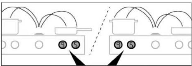
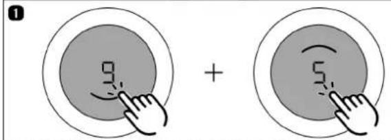
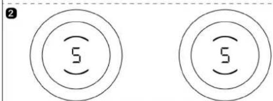
Fig. 5.26 Activating the bridging function
Deactivating the bridging function
▶ Set the power level to 0.
or
▶ Touch command on both control knobs at the same time.
- An acoustic signal can be heard and the bridging function is deactivated.
- The current power levels are retained.
• Each cooking zone then goes back to being operated separately.
5.5.7 Pause function
With the pause function all cooking zones can be quickly and easily deactivated temporarily. When the function is cancelled, operation resumes at the original settings. The cooking session can be paused for a maximum of 10 minutes. Once 10 minutes have lapsed, the cooking session is automatically ended.
During the pause, fan function is not interrupted. Active bridging and short-time timer functions remain active. Active cooking zone timers are stopped.
Activating the pause function
▶ Double tap the cooktop extractor control knob
- appears in the cooktop extractor control knob display | fading in and out.
- The cooktop control knob displays are dimmed.
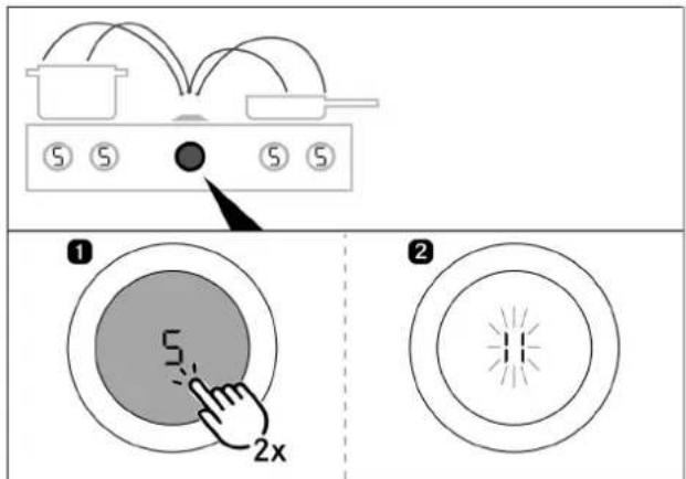
Fig. 5.27 Activating the pause function
Deactivating the pause function
▶ Double tap the cooktop extractor control knob
- The cooktop control knob displays light up again.
- Paused cooking zone timers resume their countdown.
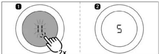
Fig. 5.28 Deactivating the pause function
5.5.8 Pan size recognition
On induction cooktops the cooking zone recognises the size of the cookware automatically and only targets the energy at that area. It also recognises cookware that is unsuitable or too small, or if there is no cookware present. A cooking zone is not working if U are alternated in the display. This happens if
- it is switched on without cookware or with unsuitable cookware;
- the base diameter of the cookware is too small;
- the cookware is removed from a switched-on cooking zone. If no pot is recognised 10 minutes after setting a power level, the cooking zone will switch off automatically.
5.6 Cooktop function menu
Every appliance offers different additional functions. These can be selected and activated via a function menu. Only the functions available for each type of appliance are shown in the corresponding function menu.
| Menu item Designation | |
| lu | Heat retention function (3 levels) |
| 2t | Cooking zone timer |
| 3A | Automatic heat up function |
Tab. 5.5 Function menu on induction cooktops
Tab. 5.6 Gas cooktop function menu
| Menu item Designation | |
| lo | Additional ring switching |
| 2u | Heat retention function (3 levels) |
| 3t | Cooking zone timer |
| 4A | Automatic heat up function |
Tab. 5.7 Function menu on Hyper and HiLight cooktops
| Menu item Designation | |
| IC | Cleaning function |
Tab. 5.8 Tepan stainless steel grill function menu
5.6.1 Calling up the function menu
▶ Touch the cooktop control knob
• The function menu is opened.
- The first menu item is shown in the control knob display.
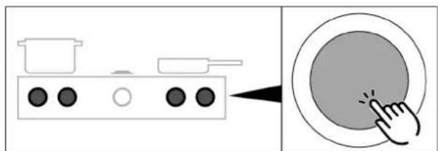
natural_image
Diagram showing a cooking pot with three panes and a button, connected to a circular button with a finger pointing at it (no text or symbols)Fig. 5.29 Accessing a cooktop function menu
5.6.2 Additional ring switching - 2-ring, 3-ring, roaster
An additional, larger ring can be easily switched on. This enables rapid adjustment to the cookware used.
- Additional ring switching can also be activated or deactivated when the heat-up, timer and heat retention functions are active.
- On the HiLight cooktop the 3-ring/roaster heating element is treated as a second ring.
- The last ring selection to be set is saved for the next cooking session.
Activating additional rings (2-ring/3-ring additional switching)
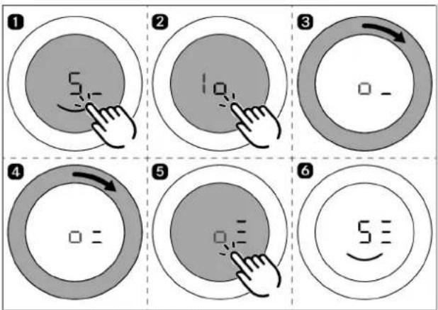
Fig. 5.30 Activating additional rings
- The second or third ring is activated in the chosen cooking zone.
- The cooking session is continued at the set power level with two or three active rings.
- The number of active rings is shown in the control knob display next to the power level (e.g. 5c, o5): 5=
Deactivating additional rings
▶ Repeat the above steps, but select fewer active rings in the function menu.
- The cooking session is continued at the set power level with the selected number of rings.
5.6.3 Variable heat retention function
Depending on the application or food used, it is possible to choose from 3 heat retention levels at different temperatures:
| heat retention level Symbol Temperature | |
| 1 (melting) ≈ 42°C | - |
| 2 (keeping warm) ≈ 74°C | - |
| 3 (simmering) ≈ 94°C | - |
Tab. 5.9 Heat retention levels
- The maximum duration of the heat retention function is limited to 8 hours.
In practice the temperatures of the heat retention levels may vary slightly as they are influenced by the cookware, the amount of food and the different heating technologies. The temperatures can also vary due to the influence of the cooktop extractor.
Activating the heat retention function on induction cooktops
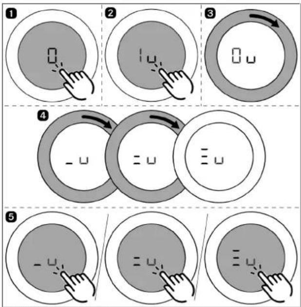
Fig. 5.31 Activating the heat retention function on induction cooktops
• An acoustic signal is heard.
- The selected heat retention level is activated.
- is shown in the control knob / = displayed.
Activating the heat retention function on Hyper and HiLight cooktops
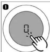
natural_image
Hand cursor clicking a button on a circular button (no text or symbols visible)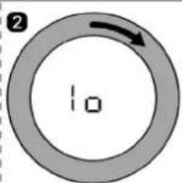
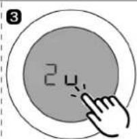
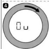
natural_image
Diagram showing two overlapping circular shapes with a curved arrow indicating rotation (no text or symbols)
natural_image
Simple line drawing of a hand pressing a button on a circular button (no text or symbols)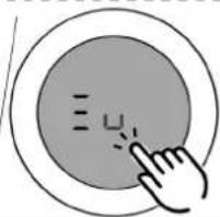
natural_image
Hand cursor clicking a button on a circular interface (no text or symbols visible)Fig. 5.32 Activating the heat retention function on radiant bodies
• An acoustic signal is heard.
- The selected heat retention level is activated.
- is shown in the control knob / = displayed.
Increasing or reducing the active heat retention level
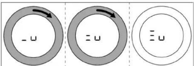
Fig. 5.33 Increasing the active heat retention level
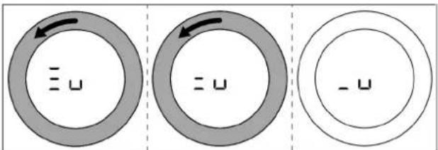
Fig. 5.34 Reducing the active heat retention level
Deactivating the heat retention function

flowchart
graph LR
    A[" "] --> B[" "]
    B --> C[" "]
    C --> D[" "]
    D --> E[" "]
    style A fill:#f9f,stroke:#333
    style B fill:#f9f,stroke:#333
    style C fill:#f9f,stroke:#333
    style D fill:#f9f,stroke:#333
natural_image
Simple concentric circle diagram with a central square and number 2, no text or symbols present.Fig. 5.35 Deactivating the heat retention function
- The cooking zone is deactivated and the control knob display shows displayed.
5.6.4 Cooking zone timer
This automatic cut-off function automatically switches off the selected cooking zone once a preset time has lapsed. You can set a time from 30 seconds to 120 minutes for the cooking zone timer.
Activating cooking zone timers
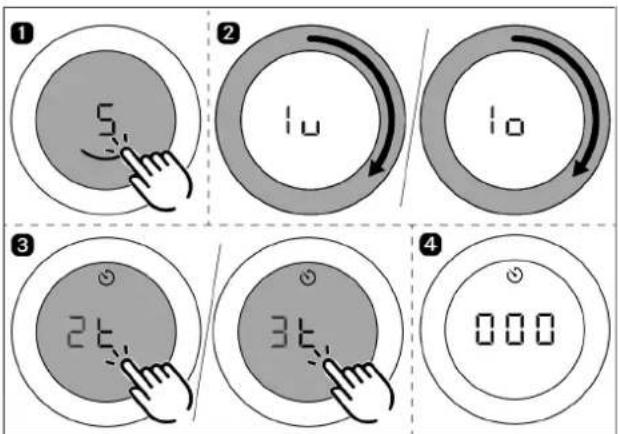
Fig. 5.36 Activating cooking zone timers
- The cooking zone timer is activated for the chosen cooking zone.
- The control knob display shows the time to be set beginning at □ and the timer symbol 📊 displayed.
- If no time is set within 4 seconds, the cooking zone timer is deactivated. The control knob display goes back to the current cooking session.
Setting the time and starting the cooking zone timer
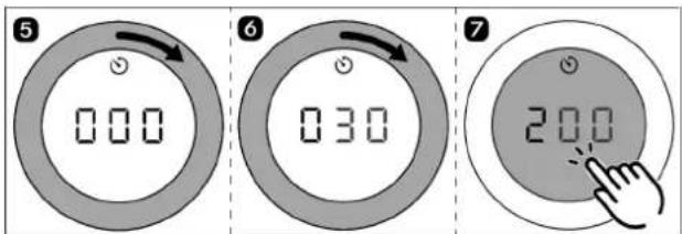
Fig. 5.37 Turning the knob ring clockwise
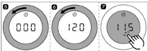
Fig. 5.38 Turning the knob ring anticlockwise
Setting range 0–10 min 10–20 min 20–120 min
Setting accuracy 30 sec. 1 min 5 min
Tab. 5.10 Setting accuracy
- After confirming with a touch command, an acoustic signal is heard, the cooking zone timer is activated and the set time starts to count down.
- The control knob display changes to the current cooking session and the timer symbol 📋 displayed.
- The set power level and the remaining time are shown alternately in the control knob display for 3 seconds.
- When 2 minutes are left, the remaining time is shown in seconds.
- Once the remaining time is less than 5 seconds, the remaining time flashes.
Changing the active cooking zone timer
▶ Repeat the steps to activate the cooking zone timer.
▶ Change the set time and restart the cooking zone timer.
Switching the cooking zone timer off early
▶ Repeat the steps to activate the cooking zone timer.
▶ Reduce the set time to and confirm.
● Active cooking sessions are resumed unchanged. Or
▶ Turn the knob ring to power level appears in the cooktop extractor control knob display.
- An acoustic signal sounds, the cooking zone is switched off and the active cooking zone timer finishes.
Lapsed cooking zone timers
• The cooking zone switches off automatically.
• An acoustic signal is heard.
- The control knob display shows and the timer symbol flashing.
- After 5 seconds the acoustic signal and the flashing display are automatically deactivated.
The flashing display and acoustic signal can be stopped early with a touch command on the control knob.
5.6.5 Automatic heat up function
When the automatic heat up function is activated, the cooking zone works at full power for a certain time and is then automatically reset to the previously set level.
| Power level (continuous cooking level) | Cooking times in min:sec |
| 1 | 00:40 |
| 2 | 1:00 |
| 3 | 2:00 |
| 4 | 3:00 |
| 5 | 4:20 |
| 6 | 7:00 |
| 7 | 2:00 |
| 8 | 3:00 |
Tab. 5.11 Overview of induction and gas cooktop heating times
| Power level (continuous cooking level) | Cooking times in min:sec |
| 1 | 1:00 |
| 2 | 3:00 |
| 3 | 4:48 |
| 4 | 6:30 |
| 5 | 8:30 |
| 6 | 2:30 |
| 7 | 3:30 |
| 8 | 4:30 |
Tab. 5.12 Overview of Hyper and HiLight cooktop heating times
If the cooking zone power level is increased while the automatic heat up function is active, the automatic heat up function remains active. The heating time is adjusted accordingly.
If the cooking zone power level is decreased while the automatic heat up function is active, the automatic heat up function is deactivated.
Activating the automatic heat up function
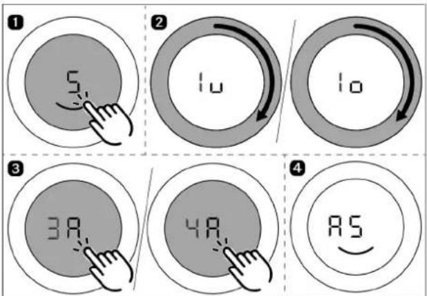
Fig. 5.39 Activating the automatic heat up function
- An acoustic signal is heard, the automatic heat up function is activated and the corresponding timer counts down.
- The control knob display shows the heat-up symbol and the set power level (e.g. AS
Deactivating the automatic heat up function early
The activated automatic heat up function will end prematurely if you
▶ reduce the power level (continuous cooking level);
▶ set the 9 power level;
▶ the power setting The power setting;
▶ activate the power setting;
▶ switch off the cooktop.
Time lapsed
- When the heat up time has lapsed, the previously set continuous cooking level will be activated.
• An acoustic signal is heard.
• The heat-up symbol will no longer be displayed.
5.6.6 Cleaning function
The cleaning function adjusts the Tepan stainless steel grill to a constant temperature of 70^ C, which is perfect for cleaning. This temperature is then maintained for 10 minutes.
Activating the cleaning function
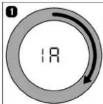
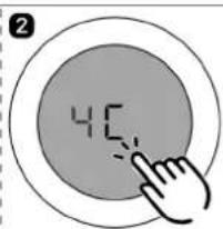
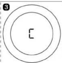
natural_image
Simple concentric circle diagram with a central 'C' and number '3' in the top-left corner (no text or symbols within the circles)Fig. 5.40 Activating the cleaning function
- The cleaning function is activated and the Tepan stainless steel grill is heated to 70 °C.
- Both control knobs show and both cooking zone indicators flash during the warm-up phase.
- As soon as the cleaning temperature is reached, the cooking zone indicators are permanently lit and it is possible to start cleaning.
Deactivating the cleaning function
▶ Turn a knob ring anticlockwise.
• The cleaning function is deactivated.

When the knob ring is turned clockwise, a higher power level is activated and cleaning must be stopped immediately (risk of burns).
6 Configuration menu
6.1 Menu overview
| Menu item Setting | |
| C0 | Acoustic signal volume |
| C1 | Demo mode |
| C2 | Speed of the cover flap motors |
| C3 | Exhaust air/recirculation mode and filter unit selection |
| C4 | Operation with or without a wall sleeve (only in exhaust air mode) |
| C5 | Manual operation of the cover flap motors |
| C6 | Switching fan PWM values PKA/PKAS |
| C7 | Installation of left cooktop 0°/180° |
| C8 | Installation of right cooktop 0°/180° |
| C9 | Pause function activated/deactivated |
| CA | Number of fans installed |
| Cb | Perform software update |
| Cc | Perform data export |
| Cd | Software version indicator |
Tab. 6.1 Menu overview
| Menu item Setting | |
| CE | GPU configuration |
| CF | Gas burner characteristic curves |
| Ch | GPU reset |
Tab. 6.2 Gas configuration menu
6.2 How to use the menu
6.2.1 Calling up the menu
The menu can only be called up when the system is switched on but all appliances are inactive (= power level 0).
▶ Extra-long press on the cooktop extractor control knob.
▶ An animation appears (= prompt to turn).
▶ Turn the knob ring clockwise by at least 90^ .
- The menu is called up and the first menu item is displayed.
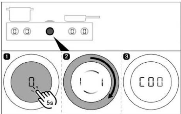
Fig. 6.1 Calling up the menu
6.2.2 Calling up the gas cooktop menu
▶ Extra-long press on a gas cooktop control knob.
▶ An animation appears (= prompt to turn).
▶ Turn the knob ring clockwise by at least 90°.
- The menu is called up and the first menu item is displayed.
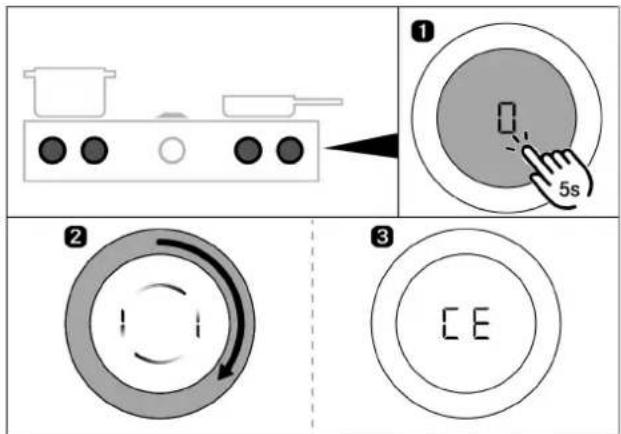
Fig. 6.2 Calling up the gas cooktop menu
6.2.3 Entering settings
Explanation of the menu item display (e.g. 123) Number in middle segment = menu item (100% brightness) Number in right-hand segment = current setting (50% brightness)
Selecting and confirming menu items
▶ Turn the knob ring to the required menu item.
▶ Tap to confirm.
Making, confirming and saving settings
▶ Turn the knob ring to the required setting.
▶ Tap to confirm the setting.
- The system adopts and saves the settings made when you exit the corresponding menu item or the menu itself.
6.2.4 Closing the menu
▶ Turn the knob ring to appears in the cooktop extractor control knob display.
▶ Tap to confirm the selection.
- The menu is closed and the standard display appears.
or
- The menu can be exited at any point by means of a long touch.
Settings that have not yet been confirmed will be lost.
or
- If no settings are changed in a menu or submenu item for 2 minutes, the configuration menu is closed automatically and the display goes out. The settings made are saved automatically.
6.3 Initial operation
When used for the first time, the system must be configured. It is essential to select the correct settings from the menu items for the basic configuration.
6.3.1 Basic configuration
Menu item: exhaust air or recirculation mode (incl. filter unit selection)
In recirculation mode, the correct selection of the filter unit automatically sets the maximum recirculation filter service life and adjusts the filter timer accordingly.
| Setting Operating mode Filter unit (service life) | |
| 0 | Exhaust air mode No filter required |
| 2 | Recirculation mode ULB3X (600 h) (factory setting) |
| 3 | Recirculation mode ULBF (300 h) |
Tab. 6.3 Exhaust air or recirculation mode and filter unit selection
Menu item: operation with or without a wall sleeve (only in exhaust air mode)
If a wall sleeve is used in exhaust air mode, when activating the cooktop extractor a higher power level is automatically and temporarily activated so that the wall sleeve opens properly (wall sleeve function).
Prerequisite: The exhaust air mode setting was selected in the menu item [3]
| Setting Wall sleeve | |
| Operation without wall sleeve | |
| Operation with wall sleeve (factory setting) | |
Tab. 6.4 Operation with or without a wall sleeve
Menu item : Number of fans installed
If an additional fan is used when the system is installed, it must be activated in the menu. (Not applicable in the case of ULIE additional duct fan)
| Setting Number of fans | |
| 1 | One fan connected |
| 2 | Two fans connected |
Tab. 6.5 Number of fans installed
6.4 Description of the other menu items
6.4.1 Menu item C0: Volume of the acoustic signals
| Setting Acoustic signal volume | |
| 0 | 100% (factory setting) |
| 1 | 10% |
| 2 | 20% |
| 3 | 30% |
| 4 | 40% |
| 5 | 50% |
| 6 | 60% |
| 7 | 70% |
| 8 | 80% |
| 9 | 90% |
Tab. 6.6 Acoustic signal volume
6.4.2 Menu item C1: Demo mode
In demo mode all control knob functions are available and the electrical cover flap and fan are operative. The cooktop heating function is deactivated. Demo mode is used, for example, for exhibitions.
| Setting Operating mode | |
| ☐ | Normal operation (factory setting) |
| | | Demo mode |
Tab. 6.7 Normal operation or demo mode
6.4.3 Menu item C2: Speed of the cover flap motors
| Setting Cover flap speed | |
| 0 | 100% |
| 1 | 40% |
| 2 | 46.7% |
| 3 | 53.4% |
| 4 | 60% |
| 5 | 66.7% |
| 6 | 73.3% (factory setting) |
| 7 | 80% |
| 8 | 86.7% |
| 9 | 93.3% |
Tab. 6.8 Speed of the cover flap motors
6.4.4 Menu item C5: Manual operation of the cover flap motors
If setting 1 or 2 is selected in menu item C5, the cover flap can be manually opened or closed with a long press on the touch surface of the control knob.
| Setting Function | |
| ☐ | Leave menu item |
| 1 | Opening the cover flap |
| 2 | Closing the cover flap |
Tab. 6.9 Manual operation of the cover flap motors
6.4.5 Menu item C6: switching fan PWM values
| Setting Configuration | ||
| Fan PWM valuesPKA3/PKA3AB | Factory setting onPKA3/PKA3AB | |
| Fan PWM valuesPKAS3/PKAS3AB | Factory setting onPKAS3/PKAS3AB | |
Tab. 6.10 switching fan PWM values
6.4.6 Menu item C7: Installation of left cooktop 0°/180°
| Setting Set-up | |
| ☐ | Standard installation (factory setting) |
| I | Installation rotated by 180° |
Tab. 6.11 Cooktop set-up
6.4.7 Menu item C8: Installation of right cooktop 0°/180°
| Setting Set-up | |
| ☐ | Standard installation (factory setting) |
| I | Installation rotated by 180° |
Tab. 6.12 Cooktop set-up
6.4.8 Menu item C9: Pause function activated/deactivated
| Setting Function | |
| ☐ | Pause function cannot be set |
| I | Pause function can be set (factory setting) |
Tab. 6.13 Pause function activated/deactivated
6.4.9 Menu item Cb: software update
Preparing the USB stick
▶ Download the update ZIP file from the BORA website (https://www.bora.com/service/download) or use the QR code
▶ Unzip the ZIP file.
The unzipped updated data must be loaded onto a FAT 32 formatted USB stick.

The update files must not be moved to a subfolder on the USB stick.
Always use the latest update files. The files must not be modified.
When a link with the USB stick is established, the extractor automatically detects which cooktops are connected and updates them with the appropriate update file.
Instruction video
▶ Scan the code to access the instruction video.
Performing a software update
Only fully functional cooktops can be updated. Ensure that it functions properly.
▶ Ensure that the appliance can be accessed from underneath.
▶ Fitted drawers and cable protectors must be removed or disassembled.
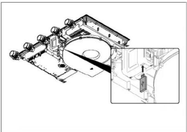
natural_image
Technical line drawing of a mechanical assembly with an inset showing a close-up of a component (no text or symbols present)Fig. 6.3 Inserting the USB stick
▶ Insert the USB stick into the slot on the cooktop extractor.
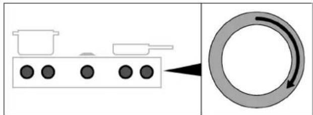
natural_image
Diagram showing a container with three black dots and a circular ring with a black arrow indicating rotation (no text or symbols)Fig. 6.4 Activating the system
▶ Activate the whole system using any control knob.
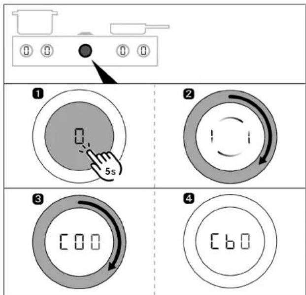
Fig. 6.5 Accessing the configuration menu
▶ Press the fan knob until the second acoustic signal is heard.
▶ Follow the prompt by turning the knob ring at least 90^ clockwise.
▶ You have reached the configuration menu when "☐ displayed.
▶ Turn the knob ring clockwise to menu item "CbO
The "b" is shown at 100% brightness as soon as the USB stick is detected by the appliance.
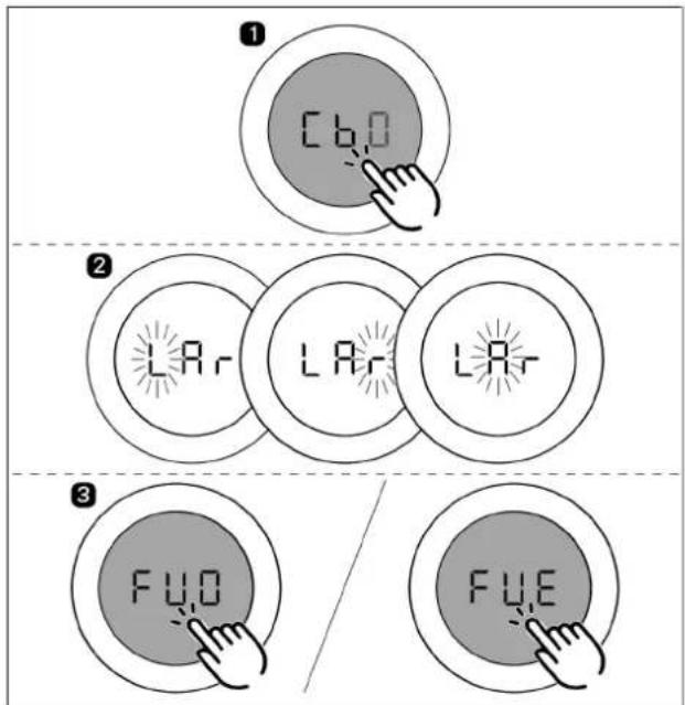
Fig. 6.6 Starting a software update
▶ Start the update by briefly touching “CbO
- Update time: approx. 1–2 minutes.
- Display on control knob: LIf updating the whole system, - L if only the cooktops are being updated.
• The characters will then flash one after the other:
- L flashing: left cooktop upgrade in progress.
- flashing: right cooktop upgrade in progress.
- A flashing: cooktop extractor upgrade in progress.
- If the software update has been installed successfully, an acoustic signal will be heard and the system will display "FUO"
- If an error occurs during the update, "F is displayed.
If the update fails, follow the instructions in the "Troubleshooting" chapter.
▶ Acknowledge this by tapping the display.
▶ Remove the USB stick from the appliance.
Final check
Perform data export
i Wait at least 2 minutes between software update and data export.
▶ Insert the USB stick into the slot on the cooktop extractor.
▶ Activate the whole system using any control knob.
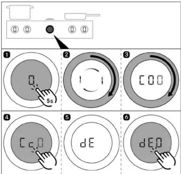
Fig. 6.7 Perform data export
▶ Press the fan knob until the second acoustic signal is heard.
▶ Follow the prompt by turning the knob ring at least 90° clockwise.
- You have reached the configuration menu when "☐" is displayed.
▶ Turn the knob ring clockwise to menu item “☐.c☐
▶ Start the update by briefly touching “☐c☐
- During data export, "ds displayed on the control knob.
- When the data export is complete, "B" is displayed on the control knob.
- If an error occurs during the data export, "is displayed.
▶ Acknowledge this by tapping the display.
▶ Remove the USB stick from the appliance.
Checking the software version
i Wait at least 2 minutes between updating the software and checking the software version.
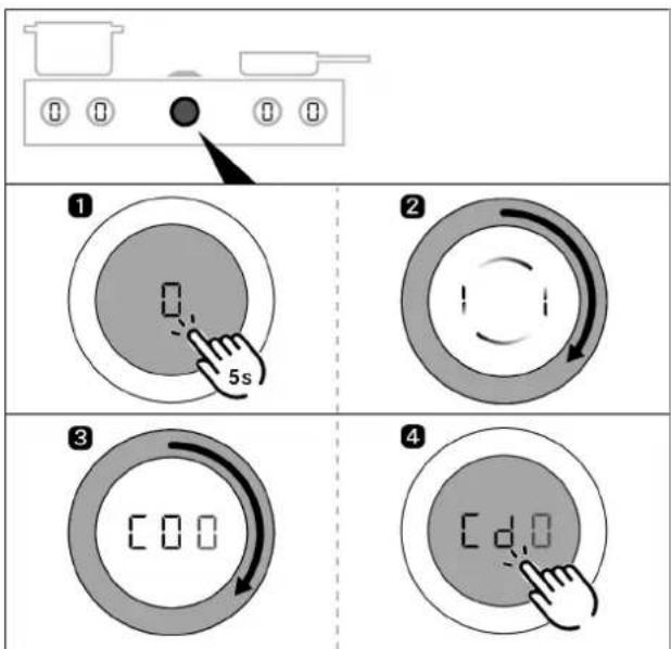
Fig. 6.8 Checking the software version
▶ Press the fan knob until the second acoustic signal is heard.
▶ Follow the prompt by turning the knob ring at least 90^ clockwise.
- You have reached the configuration menu when "☐ is □ displayed.
▶ Turn the knob ring clockwise to menu item "CDO
▶ Start the update by briefly touching “”, the current software version is displayed.
▶ Turn the knob ring clockwise to display the software version of the corresponding component (cooktop on the left, cooktop extractor or cooktop on the right)
- The software version displayed must match the software version of the files on your USB stick.
- You can exit the menu by turning the knob ring until you see "End" and then tapping the display.
Troubleshooting
- If the "in menu item" is not lit up, the system was unable to detect a USB stick.
- If the "C" in menu item " "Is not lit up, the system was unable to detect a USB stick.
If the USB stick is not detected or the error messages "FVE d EE" appear, the following steps must be taken:
Remove the stick for 5 seconds and then reinsert it. It can take up to 5 seconds for the USB stick to be detected.
or
▶ Leave the stick in the appliance and switch off the power supply for 1 minute.
▶ If necessary, reformat the USB stick to FAT32 and copy the files as indicated.
Troubleshooting if an update fails " "
The file names of the update files must not be modified (especially “_.upd”).
▶ Check that all files are on the stick and have not been moved to a folder.
▶ Call up the configuration menu “” and insert the USB stick.
6.4.10 Menu item Cc: data export
▶ Start the data export by touching the display.
6.4.11 Menu item Cd: software version indicator
The software currently used for all connected appliances is shown:
- left cooktop
- Cooktop extractor
• right cooktop
It is shown as follows:
| Indicator 1 (appliance) | Indicator 2 (software version) |
| LFT | xxx (= left cooktop software version) |
| FAN | xxx (= cooktop extractor software version) |
| r,t | xxx (= right cooktop software version) |
Tab. 6.14 software version indicator
The software versions are displayed one after the other by twisting the control knob clockwise. The menu then closes.
6.5 Gas configuration menu item
The burner nozzles, gas type, gas pressure and gas characteristic curve may only be changed by a certified engineer or BORA service technician. They also assume responsibility for the proper gas installation and commissioning.
It is important that the gas type, gas pressure and characteristic curve are set correctly to ensure safe, failure-free operation of the gas cooktop.
6.5.1 Menu item CE: GPU configuration
Under menu item CE (GPU) the minimum power of each burner and gas type/pressure is regulated.
▶ Select the correct setting.
| Setting Gas type and gas pressure | |
| ☐ | G20, 20 mbar (Factory setting) |
| G25, 20 mbar | |
| 4 | G30, 29 mbar |
| G30/G31, 37 mbar | |
| 5 | G30, 50 mbar |
| G30/G31, 50 mbar | |
| A | G20, 13 mbar |
| b | G25, 25 mbar |
| G25.3, 25 mbar | |
| C | G20, 25 mbar |
Tab. 6.15 Setting the gas type and gas pressure
6.5.2 Menu item CF: Gas burner characteristic curves
You can select the characteristic curves for the gas burners here. The characteristic curves regulate the minimum gas burner power values. The minimum power levels are adjusted using the characteristic curves. Depending on the installation situation and the influence of the cooktop extractor, if necessary, the characteristic curve can be changed.
Characteristic curve A:
A enables the fine tuning of the power values, which can only be adjusted in the best-case scenario and only in the case of natural gas (G20, G25, G25.3). The best-case scenario is when:
- no cooktop extractor is in operation; or
- the cooktop, when using the cooktop extractor in exhaust air mode, is used with sufficient ventilation; or
- the cooktop, when using the cooktop extractor in recirculation mode is used with a sufficient return flow aperture and the cooktop extractor does not have a negative influence on the gas flame.
Characteristic curve B:
B is the factory default characteristic curve with balanced adjustment of the individual power levels.
Characteristic curve C:
C increases the lower power levels and should only be used in the event of a negative influence from the cooktop extractor.
▶ Select the appropriate characteristic curve.
| Setting Gas burner characteristic curves | |
| 0 | Characteristic curve A |
| 1 | Characteristic curve B (factory setting) |
| 2 | Characteristic curve C |
Tab. 6.16 Characteristic curves for the gas burner
If the gas flame goes out, is excessively affected by the extractor and/or the flame is not as it should be (e.g. soot production, flame blowback, etc.), the characteristic curve must be increased, as well as the ventilation in exhaust air mode, if necessary, or the return flow aperture in recirculation mode.
6.5.3 Menu item Ch: GPU reset
This menu item provides a reset function. This reset function can be used in the case of faults and errors and during initial operation if the gas cooktop does not react (does not ignite). The set values for the gas type, pressure and characteristic curve remain unchanged and are not affected by the reset.
▶ Perform a reset if necessary.
| Setting GPU reset | |
| Resetting a locked GPU | |
Tab. 6.17 Resetting a locked GPU
7 Cleaning and maintenance
▶ Observe all safety and warning information (see "2 Safety").
▶ Follow the enclosed manufacturer's information.
i Clean stainless steel surfaces in the polishing direction only.
Do not use stainless steel care products on the stainless steel surfaces or the stainless steel grill surface.
When conducting scheduled cleaning and maintenance, ensure that the cooktop and cooktop extractor are fully switched off and cooled so as to prevent injury.
- Regular cleaning and maintenance ensures long service life of the product and optimal function.
▶ Adhere to the following cleaning and maintenance cycles.
Control knob cleaning cycles
| Component Cleaning cycles |
| Knob ring/knob housing Immediately after every soiling |
Tab. 7.1 Control knob cleaning cycles
Cooktop extractor cleaning cycles
| Component Cleaning cycles | |
| Cooktop extractor interior and surface | After cooking very greasy dishes; at least once a week |
| Air inlet nozzle, grease filter unit | After cooking very greasy dishes; at least once a week |
| Cover flap, grease filter and filter tray | After cooking very greasy dishes; at least once a week. |
| Maintenance tray When necessary (in recirculation mode at the latest when the activated charcoal filter is replaced) | |
| Activated charcoal filter (with recirculation only) | Replace if odours have built up or the service life has expired |
Tab. 7.2 Cleaning cycles
Cooktop cleaning cycles
| Component Cleaning cycles |
| Cooktop Clean well immediately after soiling,using conventional detergents |
| Only on the gas cooktop: |
| Pan supports gas burner parts Clean well immediately after soiling,using conventional detergents |
Tab. 7.3 Cooktop cleaning cycles
7.1 Cleaning agents
Due to the use of aggressive cleaning agents and abrasion caused by the pot bases the surface will become damaged and dark stains will occur.
▶ Never use steam cleaners, abrasive sponges, scouring pads or chemically aggressive cleaning agents (e.g. oven cleaner spray).
▶ Make sure that the cleaning agent does not contain any sand, soda, acids, lyes or chloride.
7.1.1 Cleaning products for glass ceramic cooktops
To clean the cooktop, you need a special glass ceramic scraper and suitable cleaning agents.
Do not use the glass ceramic scraper in the curved cooking zone of the wok cooktop.
7.1.2 Cleaning products for the Tepan stainless steel grill
To clean the Tepan stainless steel grill you need a special Tepan spatula and suitable cleaning agents. In the case of heavy soiling, a new sponge scourer can be used.
7.2 Cleaning the cooktop extractor
Grease particles and limescale residues from cooking vapours can settle on the surface and in the extraction system.
▶ Clean the cooktop extractor components in accordance with the cleaning cycles.
▶ Remove the cover flap, grease filter and filter tray prior to cleaning.
▶ Clean the surfaces using a soft, damp cloth, detergent or a mild window cleaning agent.
▶ Soften dried on dirt using a damp cloth (do not scrape it off!).
Cover flap cleaning position
▶ Ensure that the cooktop extractor is switched on but inactive (= power level 0).
▶ Activate the cleaning function on the cooktop extractor (see "5 Functions and operation").
• The cover flap opens and displayed.
• The fan motor will not start or will switch off if running.
7.2.1 Removing the cover flap, grease filter and filter tray
The grease filter components can only be removed when the cooktop extractor cleaning function is active.
▶ Lift the cover flap up to remove it.
▶ Reach into the opening in the cooktop extractor and remove the grease filter and filter tray.
- appears on the cooktop extractor's control knob displayed.
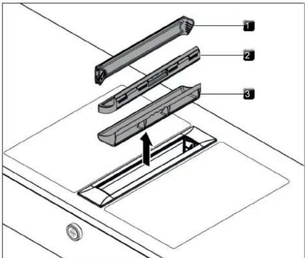
Fig. 7.1 Removing the grease filter components
[1] Cover flap
[2] Grease filter
[3] Filter tray
7.2.2 Fitting the cover flap, grease filter and filter tray
▶ Insert the filter tray in the opening on the extractor.
▶ Insert the grease filter into the opening in the extractor.
▶ Ensure that the grease filter sits correctly in the gap in the housing.
▶ Lay the cover flap on its side next to the extractor opening.
▶ Allow the cover flap to slide diagonally into the holder.
▶ Press the ends of the cover flap lightly from above until you hear them click into place.
▶ Make sure that the cover flap has been fitted correctly.
- If the cover flap is not properly installed in its locking mechanism, it will not close fully.
- If the grease filter or cover flap has not been properly fitted, the error message 'E012', 'E013' or 'FF out' appears on the control knob's display (see "8 Troubleshooting").
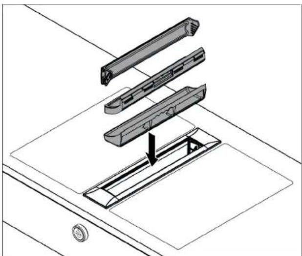
natural_image
Technical line drawing of a mechanical assembly with three components and an arrow indicating assembly direction (no text or symbols)Fig. 7.2 Fitting the components
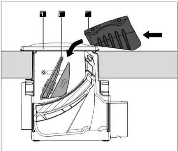
Fig. 7.3 Fitting the cover flap
[1] Extractor opening
[2] Holder
[3] Cover flap
7.2.3 Removing the maintenance tray
The maintenance tray cannot be removed in the following installation situations:
- single installation
• second adjacent extractor - adjacent wok cooktop
To remove the maintenance tray, the grease filter and filter tray must be removed first.
▶ Turn the two levers of the lock outwards 90^ to unlock the maintenance tray.
▶ Lift the maintenance tray out of the cooktop extractor.
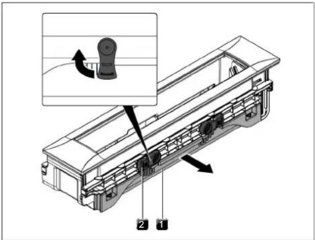
Fig. 7.4 Removing the maintenance tray
[1] Maintenance tray
[2] Lock
7.2.4 Installing the maintenance tray
▶ Slide the maintenance tray into the cooktop extractor.
▶ Turn the two levers of the lock downwards to lock the maintenance tray.
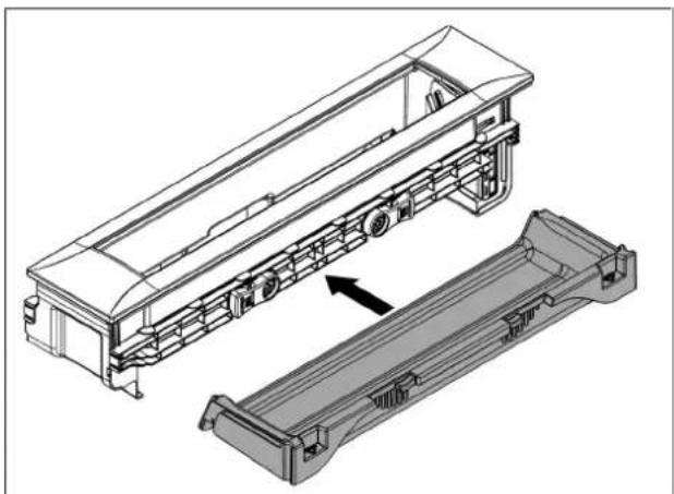
natural_image
Technical line drawing of a multi-axle industrial vehicle chassis with internal components and an arrow indicating assembly direction (no text or symbols present)Fig. 7.5 Installing the maintenance tray
7.2.5 Cleaning the components
The cover flap, grease filter, filter tray and maintenance tray can be cleaned by hand or in the dishwasher.
Manual cleaning
▶ Use a cleaner and degreaser in one.
▶ Rinse the components with hot water.
▶ Clean the components with a soft brush.
▶ Rinse the components well after cleaning.
Cleaning in the dishwasher
▶ Remove coarse food residues from the components.
▶ Place the components in the dishwasher.
▶ No water should be able to gather in the components.
▶ Rinse the components with a rinsing program at a maximum temperature of 65^ C.
If the stainless steel grease filter can no longer be fully cleaned, it must be replaced (Warranty, technical service, spare parts, accessories).
7.2.6 Ending the cooktop extractor cleaning process
To end the cleaning function, all grease filter components must be correctly fitted.
▶ Turn the knob ring or touch the control knob on the cooktop extractor.
• This deactivates the cleaning function.
- The display on the control knob changes from C to 0 and the cooktop extractor is ready for use.
- If the grease filter or cover flap has not been properly fitted, the error message 'E012', 'E013' or 'FF out' appears on the control knob's display (see "8 Troubleshooting").
7.2.7 Replacing the recirculated air filter
In recirculation mode, an additional activated charcoal filter is used. The activated charcoal filter absorbs cooking odours. The activated charcoal filter is installed on the plinth fan or the duct system. If an activated charcoal filter has reached the end of its service life, the filter service display will appear and the filter must be replaced. After replacing the filter, the filter service life must be reset.
▶ Change the activated charcoal filter when the filter service display appears.
- You can see the service life and a description of how to change the filter in the activated charcoal filter operating instructions.
▶ Reset the filter service display (see "5.4.5 Filter service life and filter service display").
You can obtain activated charcoal filters from your specialist supplier or from the BORA Shop via the website at http://www.mybora.com.
7.3 Cleaning the cooktops
Any changes in colour or glossy spots do not mean that the cooktop is damaged. They do not affect the functionality of the cooktop or the stability of the glass ceramic panel.
Changes in the colour of the cooktop are the result of residues which have not been removed and have burnt on.
Glossy spots are the result of wear by the pan base, especially if aluminium-based cookware or unsuitable cleaning agents are used. These are difficult to remove.
7.3.1 Cleaning glass ceramic cooktops
▶ Make sure that the cooktop is switched off.
▶ Wait until all cooking zones are cold.
Remove all coarse dirt and food residues from the cooktop using a glass ceramic scraper.
▶ Apply the cleaning agent to the cold cooktop.
▶ Spread the cleaning agent using kitchen roll or a clean cloth.
▶ Wipe the cooktop clean with a damp cloth.
▶ Dry the cooktop with a clean cloth.
If the cooktop is hot:
Remove stubborn residues of plastic, aluminium foil, sugar or sweet dishes from the hot cooking zone immediately using a glass ceramic scraper to prevent burning.
Heavy soiling
Remove heavy soiling and marks (limescale marks, mother-of-pearl-like shiny marks) using cleaning products while the cooktop is still warm.
▶ Wipe off any food that boils over with a damp cloth.
▶ Remove any remaining dirt with the glass ceramic scraper.
▶ Always remove any seeds, crumbs or similar that fall onto the cooktop during cooking immediately to prevent the surface getting scratched.
7.3.2 Cleaning the surface of the Tepan stainless steel grill
Any changes in colour or small scratches do not mean that the cooktop is damaged. They do not affect the functionality of the cooktop or the stability of the stainless steel grill surface. Changes in the colour of the cooktop are the result of residues which have not been removed and have burnt on.
Use the scraper only on the grill surface as otherwise other surfaces may be damaged.
Changes may occur in the surface of the grill after using the spatula or a sponge scourer.
Do not apply cleaning products to the adjoining areas between the cooktop and worktop.
Use the cleaning function to clean the Tepan stainless steel grill.
i Clean stainless steel surfaces in the polishing direction only.
Light soiling
▶ Make sure that the cooktop is switched off.
▶ Wait until the stainless steel grill surface has cooled.
▶ Remove light soiling with a damp cloth and detergent.
To prevent water or limescale stains (yellowish colouring), use a soft cloth to dry off the surfaces that have been cleaned with water.
Normal soiling
▶ Ensure that the cleaning function is activated for both grilling zones.
▶ Wait until the grilling zone indicators are no longer flashing (= optimum cleaning temperature of 70^ C).
▶ Use only clean, cold water on the grill surface.
▶ Leave the water to work for 15 minutes.
▶ Then remove all coarse dirt and food residues using a Tepan spatula.
▶ Remove the remaining dirt and water with a clean cloth.
▶ Dry the cooktop with a clean cloth.
Heavy soiling
▶ Ensure that the cleaning function is activated for both grilling zones.
▶ Wait until the grilling zone indicators are no longer flashing (= optimum cleaning temperature of 70^ C).
▶ Dilute a drop of washing-up liquid in a bowl of warm water (approx. 200 ml).
▶ Pour the liquid on the grill surface.
Leave the solution to work for approx. 5-8 minutes.
▶ Loosen burned-on food from the grill surface with a plastic brush.
▶ Remove all dirt and water with a cloth.
Pour 50 ml of water and a drop of washing-up liquid onto the grill surface.
Clean the entire grill surface using the rough side of a sponge scourer, only in the direction of the grain. Also use the Tepan spatula to help.
▶ Remove all of the remaining dirt and water with a clean cloth.
▶ Use clean, cold water on the grill surface.
▶ Remove the remaining dirt and water with a clean cloth.
▶ Dry the cooktop with a clean cloth.
7.3.3 Cleaning the components on the gas cooktop
The surface of the cast iron parts will become duller with the passing of time. This is quite normal and does not mean that the material is damaged.
Cleaning the pan supports
▶ Remove the pan support.
- Pan supports can only be cleaned by hand.
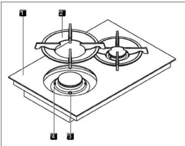
Fig. 7.6 Gas burner structure
[1] Gas cooktop
[2] Pan support
[3] Gas burner
[4] Positioning aid
The pan supports are not dishwasher safe.
Manual cleaning
▶ Use a cleaner and degreaser in one.
▶ Rinse the pan supports with hot water.
▶ Clean the pan supports with a soft brush.
▶ Rinse the pan supports well after cleaning.
▶ Dry the pan supports carefully with a clean cloth.
- In the case of particularly stubborn or burned-on dirt, the pan support can be briefly soaked in warm water with washing-up liquid. Any limescale marks can be more easily removed with diluted vinegar.
Cleaning the gas burner parts
- Do not start cleaning until the gas burner has returned to normal temperature after use.
- The burner parts are not dishwasher safe. Burner parts must only be cleaned by hand.
- Only clean with normal hot water to rinse and a conventional washing-up liquid, using a soft sponge or a normal dishcloth.
- Never scratch or scrape cooking residues off.
▶ Remove the pan support.
▶ Remove the burner cap from the burner head.
▶ Remove the burner head from the gas outlet
▶ Clean the parts of the burner.
▶ Clean all of the flame outlet openings with a non-metallic brush.
▶ Wipe the fixed parts of the burner with a damp cloth.
▶ Wipe the igniter electrode and the thermocouple carefully with a well-wrun-out cloth. - The igniter electrode must not get wet, otherwise the ignition spark will not light.
▶ Finally, dry the pan supports carefully with a clean cloth. -
Before reassembling the flame openings, burner heads and burner caps must be completely dry.
▶ Put the burner parts back together again.
▶ Position the burner head correctly on the gas outlet.
▶ Ensure that the safety thermocouple and the electric igniter are positioned in the correct opening.
▶ Position the burner cap so that it fits perfectly, sitting straight on the burner head. -
If burner parts are not positioned correctly, the electric igniter will not work.
▶ Place the pan support straight on the gas burner so it fits perfectly.
▶ Put the gas burner into operation.
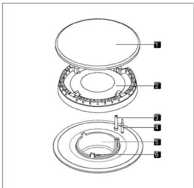
Fig. 7.7 Gas burner structure
[1] Burner cap
[2] Burner head
[3] Burner head
[4] Safety thermocouple
[5] Burner housing
[6] Gas burner nozzle
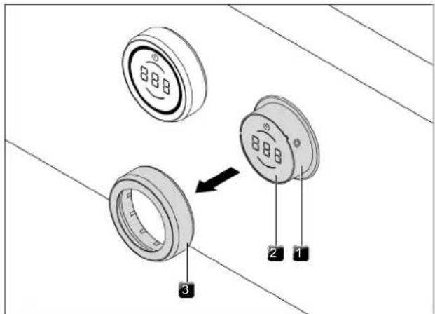
Fig. 7.8 Pull out the knob ring
[1] Knob housing
[2] Touch surface
[3] Knob ring
Cleaning the touch surface and the knob housing
▶ Remove the knob ring.
▶ Clean the touch surface and the knob housing with a soft, damp cloth.
▶ Dry the touch surface and the knob housing carefully.
▶ Place the knob ring on the knob housing.
7.4 Looking after your cooktops
▶ Never use the appliance as a work or storage surface.
▶ Do not push or pull cookware over the appliance.
▶ Always lift pots and pans.
▶ Keep the appliance clean.
▶ Remove any dirt immediately.
▶ Only use suitable cookware with the appliance.
7.5 Cleaning the control knobs
The knob rings are not dishwasher safe.
Cleaning the knob ring
The knob ring can only be cleaned by hand.
▶ Remove the knob ring from the knob housing.
▶ Use a cleaner and degreaser in one.
▶ Rinse the knob ring with hot water.
▶ Clean the knob ring with a soft brush.
▶ Rinse the knob ring well after cleaning.
▶ Dry the knob ring carefully.
▶ Place the dry knob ring back on the knob housing.
8 Troubleshooting
8.1 Cooktop extractor troubleshooting
| Operating situation Cause Remedy | ||
| The cooktop extractor cannot be switched on Knob ring missing Slot the knob ring onto the control knob | ||
| The fuse or automatic circuit breaker of the electrical wiring system in the apartment and/or house is defective | Replace the fuseSwitch the automatic circuit breaker back on | |
| The fuse or the automatic circuit breaker trips several times | Contact the BORA Service Team | |
| The power supply is disconnected Have a specialist inspect the power supply | ||
| The pause function is active Deactivate the pause function | ||
| The micro fuse in the control unit's cooling device plug connection is defective | Replace the fuse (type: T 3.15A/250V) | |
| The fan motor won't start The cover flap is not fitted or is fitted incorrectly Fit the cover flap correctly | ||
| Build-up of odours when new cooktop extractor is in operation | This is normal on brand-new appliances Odours stop forming after a few operating hours | |
| Control knob display L | The child lock is activated | Switch off the child lock (see "5.4.4 Child lock") |
| Control knob display P | Continuous operation (< 8 s) of the control knob or control knob dirty | Take your finger off the control knob or clean the knob |
| Control knob display F | End of activated charcoal filter service life reached | Fit a new activated charcoal filter (see "7 Cleaning and maintenance") |
| Control knob display FF out | The grease filter is not fitted or is fitted incorrectly | Please check if the grease filter has been correctly positioned (re-insert). |
| The cover flap sensor is faulty Contact the BORA Service Team. | ||
| Control knob display End | An object is obstructing the cover flap Remove the object | |
| The cover flap has not clicked into place in its holder | Lightly press the ends of the cover flap from above until you hear it click into place | |
| The cover flap sensor is faulty or misaligned Contact the BORA Service Team | ||
| Loss of power when the cover flap is removed Touch to acknowledge. If necessary, move the flap manually using menu item C5 (see "6.4.4 Menu item C5: Manual operation of the cover flap motors") | ||
| Control knob display E012 and E013 | the cover flap are not fitted or are fitted incorrectly | Fit the cover flap correctly |
| The cover flap sensor is faulty Contact the BORA Service Team | ||
| Control knob display E019 | Error in the touch surface values | Remove the knob ring and put it back on. Repeat the touch command. |
| Contact the BORA Service Team. | ||
| Control knob display E022 | Knob settings incorrectly interpreted, controls switch off after 4 to 8 seconds | Replace the control knob |
| Control knob display E381 | The Home In contact is interrupted | Check the Home In contact cable or bridge |
| Control knob display E383 | The Home In contact is interrupted | In exhaust air mode, open the window, for example. |
| Control knob display E385 | The fan does not rotate during operation | Check the fan connections on the control box. |
| Replace the control box. | ||
| Control knob display E386 | Fewer fans operating than configured. | Check the fan configuration in menu CA. |
| Check the fan connections on the control box. | ||
| Replace the control box. | ||
| Control knob display E387 | More fans operating than configured. | Check the fan configuration in menu CA. |
| Control knob display ES42 | Left cooktop not connected or has no power. Check the supply voltage to the left cooktop. | |
| Control knob display ES43 | Right cooktop not connected or has no power. Check the supply voltage to the right cooktop. | |
| Control knob display ES48 | Communication with the left cooktop faulty Check the cabling from the cooktop extractor to the left cooktop. | |
| Control knob display ES49 | Communication with the right cooktop faulty. Check the cabling from the cooktop extractor to the right cooktop. | |
| Control knob display ES80 | Configuration menu cannot be activated in this operating state. Power levels active on the cooktop or extractor. | Deactivate the power level on the extractor and both cooktops. |
| The extraction performance of the cooktop extractor has decreased | The stainless steel grease filter is heavily soiled Clean or replace the stainless steel grease filter | |
| The activated charcoal filter is extremely dirty (only in recirculation mode) | Replacing the activated charcoal filter | |
| There is an object in the air guiding housing (e.g. cleaning cloth) | Remove the object | |
| The fan is defective or a duct connection has become loose | Contact the BORA Service Team | |
| The cover flap is not completely open/closed Movement was stopped by an interruption to the power supply | Move the cover flap manually to the end position (see the installation instructions) | |
Tab. 8.1 Troubleshooting
8.2 Cooktop troubleshooting
| Operating situation Cause Remedy | ||
| The cooktop cannot be switched on Knob ring missing Slot the knob ring onto the control knob. | ||
| The fuse or automatic circuit breaker of the electrical wiring system in the apartment and/or building is defective. | Replace the fuse. Switch the automatic circuit breaker back on. | |
| The fuse or the automatic circuit breaker trips several times | Contact the BORA Service Team. | |
| The power supply is disconnected. Have a specialist inspect the power supply. | ||
| Build-up of odours when new cooktop extractor is in operation | This is normal on brand-new appliances Odours stop forming after a few operating hours | |
| The cooktop cooling fan continues to run when the cooktop has been switched off | The cooling fan runs until the cooktop has cooled | Wait until the cooling fan switches off automatically |
| A cooking zone or the entire cooktop switches off automatically. | The maximum cooking zone operating time has been exceeded. | Put the cooking zone back into operation. |
| The power setting is automatically shut off prematurely | The overheating protection has tripped | (see "3 Appliance description") |
| Control knob display L | The child lock is activated | Switch off the child lock (see "5.4.4 Child lock") |
| Control knob display | No or unsuitable cookware on the cooking zone Only use suitable cookware | |
| Control knob display | Continuous operation (< 8 s) of the control knob or control knob dirty | Take your finger off the control knob or clean the knob |
| Control knob display E019 | Error in the touch surface values Remove the knob ring and put it back on. Repeat the touch command. | |
| Control knob display E022 | Knob settings incorrectly interpreted, controls switch off after 4 to 8 seconds | Replace the control knob |
| Control knob display E002 E021 E057 E082, E083 | Temperature too high Allow the cooktop to cool | |
| Control knob display E581 | Operating the induction wok cooktop with only one knob. The knob was not correctly connected to port 1 on the interface circuit board according to the installation instructions. | Please connect the control knob to port 1 (zone 1) on the cooktop. |
Tab. 8.2 Troubleshooting
8.2.1 Gas cooktop troubleshooting
| Operating situation Cause Remedy | ||
| When operating for the first time, after a prolonged period without use or after changing the gas bottle: | ||
| The burner does not light during initial operation or after a long period of disuse | There is air in the gas pipe Repeat the ignition process, several times if necessary (tap the required cooking zone and set a power level). | |
| Gas cooktop does not react (servomotors do not calibrate and no ignition) | There is a communication error between the operating unit and the cooktop (e.g. in the event of a power cut). | Perform a reset (see "6.5 Gas configuration menu item") |
| The gas burner cannot be ignited electrically. The fuse or automatic circuit breaker of the apartment and/or house's electrical system is defective or has been triggered. | Change the fuse. Switch the automatic circuit breaker back on. If necessary, contact a specialist electrician. | |
| The gas flame goes out after ignition. The gas flame goes out during operation. The gas flame is uneven. | The gas burner parts (burner heads and/or the gas burner cover) are not correctly positioned. | Position the gas burner parts correctly. |
| Dirt in the gas outlet openings on the gas burner head. | Clean the gas burner parts (see "7 Cleaning and maintenance"). | |
| Control knob display E001 E002 | Error when the software is running. | Perform a reset (see "6.5 Gas configuration menu item"). |
| Disconnect the appliance from the power supply for at least 1 min. and then restart it. | ||
| Contact the BORA Service Team | ||
| All error codes E066 | Gas supply interrupted and/or no flame detected. The gas bottle is empty. | Wait 5 seconds, then touch the flashing error indicator 'E' (update error) |
| Try to ignite it again (the gas pipe needs a certain amount of time to fill after installation). | ||
| Check the gas or mains connection. | ||
| Contact the BORA Service Team. | ||
| Control knob display ES80 | Configuration menu cannot be activated in this operating state. Activate power levels on the cooktop or extractor. | Deactivate the power level on the extractor and both cooktops. |
Tab. 8.3 Troubleshooting
8.3 Dealing with errors
▶ Acknowledge the error by tapping the control knob.
▶ After troubleshooting try again and check that the problem has been solved.
▶ Try restarting the system.
▶ As a last resort, briefly disconnect the power supply.
In the event of any errors not listed here or should errors recur, please contact the BORA service team and specify the error number shown and appliance type.
9 Warranty, technical service, spare parts, accessories
▶ Observe all safety and warning information (see "2 Safety").
9.1 BORA manufacturer's warranty
BORA provides its end customers with a 2-year manufacturer's warranty for its products. The end customer is entitled to this warranty in addition to the statutory claims for defects against the sellers of our products.
The manufacturer's warranty applies to the BORA products listed here, which are sold by authorised BORA retailers or by BORA trained salespersons and are installed within the European Union (overseas territories excluded), Switzerland, Liechtenstein, Ukraine, Russia, Norway, Serbia, Israel, UK, Iceland, India, Australia and New Zealand, with the exception of BORA products labelled as universal or
accessories:
- Cooktops
• Cooktop extractor systems - Fans
The manufacturer's warranty starts as soon as the BORA product is handed over to the end customer and is valid for 2 years. Registering on www.mybora.com enables the manufacturer's warranty to be extended to 3 years.
The manufacturer's warranty requires expert installation (in accordance with the valid BORA ventilation handbook and operating instructions at the time of installation) of the BORA products by an authorised BORA retailer. During use, the end customer is to adhere to the specifications and instructions in the operating manual. When filing a warranty claim, BORA must be directly notified of the fault and the receipt must be presented. Alternatively, proof of purchase can be provided by registering on www.mybora.com.
BORA guarantees that all BORA products are free from material and production defects. The defect must exist prior to delivery of the product to the end customer. Filing a warranty claim does not interrupt the warranty period, nor shall the period start anew.
BORA will correct defects in BORA products at its own discretion by repairing or replacing the product. All costs for the correction of defects under the manufacturer's warranty shall be assumed by BORA appears in the cooktop extractor control knob display.
Expressly not covered by the BORA manufacturer's warranty are:
- BORA products that were not sold by authorised BORA dealers or salespersons trained by BORA
- Damage caused by non-adherence to the operating instructions (including product care and cleaning). This represents improper use.
- Damage caused by normal use, e.g. traces of usage on the cooktop
- Damage caused by external influences (such as transport damage, ingress of condensation, damage caused by the elements such as a lightning strike)
- Damage caused by repairs or repair attempts that were not carried out by BORA or by persons authorised by BORA.
- Damage to the glass ceramic
- Injury caused by electrical voltage fluctuations
● Secondary damage or claims for damages beyond the defect - Damage to plastic parts
Legal claims, particularly statutory claims for defects or product liability are not limited by the warranty and can be asserted free of charge.
If a defect is not covered by the manufacturer's warranty, a claim may be made against the BORA Technical Service.
. BORA shall not assume the resulting costs.
The laws of the Federal Republic of Germany apply to these warranty conditions.
You can contact us at:
- Telephone: +800 7890 0987
Monday to Thursday from 8 a.m. to 6 p.m. and Friday from 8 a.m. to 5 p.m. - Email: info@bora.com
9.1.1 Warranty extension
You can extend the warranty by registering at www.bora.com/registration.
9.2 Service
BORA Service:
see reverse side of operating and assembly instructions
In the case of faults you cannot fix yourself, contact your BORA specialised retailer or the BORA Service Teamappears in the cooktop extractor control knob display.
The BORA Service Team Team will require the type designation and serial number of your appliance (FD number).
This information is provided on the nameplate in the back of the instruction manual as well as on the bottom of the appliance.
9.3 Spare parts
▶ Only use original spare parts for repairs.
▶ Repairs may only be carried out by the BORA Service Team.
i Spare parts can be obtained from your BORA dealer, the BORA online service website at www.bora.com/service or by calling the service number provided.
9.4 Accessories
• Pro knob ring PKR3
• Pro knob ring All Black PKR3AB
Cooktop extractor accessories:
● Pro stainless steel grease filter PKA1FF
• Pro cover flap PKA1VK
• Pro cover flap All Black PKA1VKAB
• Pro filter tray PKA1FW
- Mains supply cable Type I UNLI (AUS)
- Mains supply cable Type J UNLJ (CH)
● Mains supply cable Type G UNLG (GB-IE)
• Window contact switch UFKS
Special accessory for recirculation systems:
● Air purification box flexible ULBF
- Activated charcoal filter set ULB3AS for ULB3X
Special accessory for glass ceramic cooktops:
• Glass ceramic scraper UGS
Special accessory for surface induction cooktops
- Grill pan KWGPFI
Special accessory for the wok cooktop:
- Induction wok pan HIW1
Special accessory for Tepan:
• Pro Tepan spatula PTTS1
Special accessories for gas cooktops:
● Gas nozzle set natural gas G25/25 mbar PKGDS2525
• Gas nozzle set natural gas G20/13 mbar PKGDS2013
• Gas nozzle set natural gas G20/20 mbar PKGDS2020
● Gas nozzle set natural gas G25/20 mbar PKGDS2520
● Gas nozzle set natural gas G20/25 mbar PKGDS2025
● Gas nozzle set liquid gas G30/G31 50 mbar PKGDS3050
• Gas nozzle set liquid gas G30/G31 28-30 mbar PKGDS3028
- Burner set PKGBS
• Pan support small PKGTK
• Pan support large PKGTG
10 Energy data sheets
10.1 Energy data sheet for PKA3/PKA3AB
Product information according to Commission Delegated Regulation (EU) No. 65/2014 and Regulation (EU) No. 66/2014.
| Manufacturer BORA | ||||
| Model designation PKA3/PKA3AB PKAS3/PKAS3AB | ||||
| Symbol Value Value Unit | ||||
| Energy consumption | ||||
| Yearly power consumption AEC | _food | 26.3 28.0 kWh/a | ||
| Energy efficiency class - A++ A+ - | ||||
| Energy efficiency index EEI | _food | 35.2 39.8 - | ||
| Flow volume | ||||
| Fluid dynamic efficiency | FDE_hood | 36.9 34.3 - | ||
| Fluid dynamic efficiency class | - | A | A | - |
| Minimum air flow during normal operation | - | 269 | 221 | m^3/h |
| Maximum air flow during normal operation | - | 598 | 558 | m^3/h |
| Maximum air flow when operated on the intensive level or fast mode level (power setting) | Q_max | 613 | 670 m^3/h | |
| Measured air flow rate at the best efficiency point | Q_BEP | 283.7 | 296.7 | m^3/h |
| Measured pressure at the best efficiency point | P_BEP | 507.3 | 417.0 | Pa |
| Measured electric power input at the best efficiency point | W_BEP | 108.3 | 100 W | |
| Time increase factor | f 0.7 | 0.8 | ||
| Lighting | ||||
| Lighting efficiency | LE_hood | * | * | lx/W |
| Lighting efficiency class | - | * | * | - |
| Nominal power of the lighting system | W_L | * | * | W |
| Average lighting system illumination level on the cooking surface | E_middle | * | * | lx |
| Grease filtering | ||||
| Grease filtering efficiency | GFE_hood | 83.7 74.7 | % | |
| Grease filtering efficiency class | - | C | D | - |
| Noise level | ||||
| A-rated airborne noise emission at minimum available speed in normal operation | - 47 46 | dB(A) re_1pW | ||
| A-rated airborne noise emission at maximum available speed in normal operation | - 65 67 | dB(A) re_1pW | ||
| A-rated airborne noise emission when operating on the intensive level or fast mode level (power setting) | - 65 70 | dB(A) re_1pW | ||
| Sound pressure level at minimum available speed in normal operation** | - 33 34 | LpA in dB re 20 μPa | ||
| Sound pressure level at maximum available speed in normal operation** | - 52 55 | LpA in dB re 20 μPa | ||
| Sound pressure level when operating on the intensive level or fast mode level (power setting)** | - 52 58 | LpA in dB re 20 μPa | ||
| Power consumption | ||||
| Power consumption in off mode | P_o | 0.18 0.18 | W | |
| Power consumption in standby mode | P_s | * | * | W |
Tab. 10.1 Energy labelling
* Does not apply to this product.
** Voluntary declaration
The sound pressure level has been determined from a distance of 1 m (distance-dependent level recording) on the basis of the sound power level established under EN 60704-2-13.
10.2 Energy data sheet for PKFI3
Product information according to Commission Delegated Regulation (EU) No. 65/2014 and Regulation (EU) No. 66/2014.
| Manufacturer BORA | ||
| Model identification PKFI3 | ||
| Type of hob Glass ceramic cooktop | ||
| Symbol Unit | ||
| Heating technology - Induction cooking area - | ||
| Number of cooking areas - 2 - | ||
| Front cooking area LxW 23.0 x 23.0 cm | ||
| Rear cooking area LxW 23.0 x 23.0 cm | ||
| Front cooking area EC | electric cooking | 185.0 Wh/kg |
| Rear cooking area EC | electric cooking | 176.5 Wh/kg |
| Bridged cooking areas | ECelectric cooking | 204.4 Wh/kg |
| Power consumption of the hob per kg | ECelectric hob | 188.6 Wh/kg |
Tab. 10.2 Energy data sheet for PKFI3
10.3 Energy data sheet for PKI3
Product information according to Commission Delegated Regulation (EU) No. 65/2014 and Regulation (EU) No. 66/2014.
| Manufacturer BORA | |||
| Model identification | PKI3 | ||
| Type of hob Glass ceramic cooktop | |||
| Symbol Value | Unit | ||
| Heating technology | - | Induction cooking zone | - |
| Number of cooking zones | -2- | ||
| Front cooking zone | ∅ | 23.0 | cm |
| Rear cooking zone | ∅ | 16.5 | cm |
| Front cooking zone | EC_electric cooling | 162.7 Wh/kg | |
| Rear cooking zone | EC_electric cooling | 169.3 Wh/kg | |
| Power consumption of the hob per kg | EC_electric hob | 166.0 Wh/kg | |
Tab. 10.3 Energy data sheet for PKI3
10.4 Energy data sheet for PKC3
Product information according to Commission Delegated Regulation (EU) No. 65/2014 and Regulation (EU) No. 66/2014.
| Manufacturer BORA | |||
| Model identification | PKC3 | ||
| Type of hob Glass ceramic cooktop | |||
| Symbol Value | Unit | ||
| Heating technology - Radiant cooking zones | - | ||
| Number of cooking zones | -2- | ||
| Front cooking zone | ∅ | 23.5 | cm |
| Rear cooking zone | ∅ | 20.0 | cm |
| Front cooking zone | EC_electric cooking | 180.1 Wh/kg | |
| Rear cooking zone | EC_electric cooking | 189.0 Wh/kg | |
| Power consumption of the hob per kg | EC_electric hob | 184.6 Wh/kg | |
Tab. 10.4 Energy data sheet for PKC3
10.5 Energy data sheet for PKCB3
Product information according to Commission Delegated Regulation (EU) No. 65/2014 and Regulation (EU) No. 66/2014.
| Manufacturer BORA | ||
| Model identification PKCB3 | ||
| Type of hob Glass ceramic cooktop | ||
| Symbol Value Unit | ||
| Heating technology - Radiant cooking zones - | ||
| Number of cooking zones - 2 - | ||
| Front cooking zone ∅ 23.5 cm | ||
| Rear cooking zone ∅ 16.5 cm | ||
| Front cooking zone EC | electric cooking | 180.6 Wh/kg |
| Rear cooking zone EC | electric cooking | 189.5 Wh/kg |
| Power consumption of the hob per kg EC | electric hob | 185.1 Wh/kg |
Tab. 10.5 Energy data sheet for PKCB3
10.6 Energy data sheet for PKCH3
Product information according to Commission Delegated Regulation (EU) No. 65/2014 and Regulation (EU) No. 66/2014.
| Manufacturer BORA | ||
| Model identification | PKCH3 | |
| Type of hob Glass ceramic cooktop | ||
| Symbol Value Unit | ||
| Heating technology - Radiant cooking zones - | ||
| Number of cooking zones - 2 - | ||
| Front cooking zone ∅ 23.5 cm | ||
| Rear cooking zone ∅ 20.0 cm | ||
| Front cooking zone EC | electric cooking | 175.9 Wh/kg |
| Rear cooking zone EC | electric cooking | 189.1 Wh/kg |
| Power consumption of the hob per kg EC | electric hob | 182.5 Wh/kg |
Tab. 10.6 Energy data sheet for PKCH3
10.7 Energy data sheet for PKG3
Product information according to Commission Delegated Regulation (EU) No. 65/2014 and Regulation (EU) No. 66/2014.
| Manufacturer | BORA | ||
| Model identification | PKG3 | ||
| Symbol Value | Unit | ||
| Number of gas burners | -2 | - | |
| Energy efficiency of each front burner | EE_gas burner | 60.0 | - |
| Energy efficiency of each rear burner | EE_gas burner | 60.0 | - |
| Energy efficiency of the gas hob | EE_gas hob | 60.0 | - |
Tab. 10.7 Energy data sheet for PKG3
11 Identification plates
On this page you can see the exact classification of your installed appliances. Not all of the spaces reserved for stickers need to contain an identification plate.
Upon completing installation, affix the identification plates included in the scope of delivery in the spaces below.
Identification plate
Cooktop extractor 1
(please apply here)
Identification plate
left cooktop
(please apply here)
Identification plate
right cooktop
(please apply here)
Identification plate
Cooktop extractor 2
(please apply here)
Identification plate
left cooktop
(please apply here)
Identification plate
right cooktop
(please apply here)
Notes
Operating instructions: ○Original ◎Translation
The distribution and duplication of this document, as well as the use and disclosure of its contents are prohibited unless expressly authorised. Great care was taken when devising these operating and installation instructions. However, it may be the case that later technical changes have not yet been added or the corresponding contents have not yet been modified. We apologise for this. An up-to-date version can be requested from the BORA Service team. Misprints and errors excepted.
info@boraapac.com.au
bora-australia.com.au

+800 7890 0987

(01)04251731211760(240)004564-10001

- EN Operating instructions Professional 3.0
- Contents
- General information 4
- Safety 5
- Appliance description 11
- Overview of features and functions 20
- Functions and operation 21
- Configuration menu 34
- Cleaning and maintenance 40
- Troubleshooting 45
- Warranty, technical service, spare parts, accessories 49
- Energy data sheets 51
- Identification plates 54
- General information
- Validity of the operating and installation instructions
- Liability
- Product conformity
- Directives
- Regulations
- Data protection
- Presentation of information
- Safety and warning instructions
- DANGER
- Type and source of danger
- Figures
- Safety
- Intended use
- People with limited abilities
- Children
- People with reduced physical, sensory or mental capacities
- Risk of burns from hot cookware and food
- General safety instructions
- Packaging components are a choking hazard
- Risk of electric shock or injury from damaged surfaces
- WARNING
- CAUTION
- PLEASE NOTE
- Safety instructions – operation
- Risk of burns due to power cut
- Risk of burning and fire from hot objects
- Damage caused by hot cookware
- Appliance damage
- Safety instructions – cooktop extractor operation
- Risk of smoke inhalation
- Fire risk from flambéing
- Risk of injury from moving cover flap
- Damage caused by objects or paper suctioned in
- Damage caused by grease and dirt deposits
- Increased humidity
- Safety instructions – cooktop operation
- Danger of fire caused by leaving the cooktop unattended
- Danger of explosion caused by flammable liquids
- Risk of carbon monoxide poisoning
- Risk of explosion and asphyxiation from gas
- Fire risk from naked flame
- Risk of burns from hot cooktop extractor when using gas cooktops
- Risk of burns from hot liquids boiling over
- Risk of burns from hot steam
- Risk of personal injury and appliance damage due to incorrect gas configuration
- Damage caused by sugary and salty foods
- Electromagnetic radiation
- Safety instructions – cleaning and maintenance
- Appliance damage due to soiled appliances
- Safety instructions – cleaning and maintenance of cooktop extractors
- Safety instructions – cleaning and maintenance of cooktops
- Safety instructions – repairs, servicing and spare parts
- Appliance description
- Model description
- Professional 3.0 cooktop extractors
- Professional 3.0 cooktops
- Control knob
- How it works
- Cooktop extractor appliance description
- Installation variations
- Cooktop extractor display and symbols
- Structure of the cooktop extractors
- Sensors
- Cover flap position sensor
- Grease filter position sensor
- Interface for external devices
- USB port for servicing
- Cooktop appliance description
- Display and symbols
- Layout and size of the cooking zones
- How the induction cooktops work
- Power levels
- Suitable cookware
- Noises
- How the Hyper and HiLight cooktops work
- Power setting on the Hyper cooktop
- How the Tepan stainless steel grill works
- Power levels and temperature ranges
- How the gas cooktop works
- Safety features
- Anti-trap protection
- Safety shut-down
- Cooktop extractor
- Cooktops
- Residual heat indicator
- Overheating protection
- Child lock
- Overview of features and functions
- Functions and operation
- Knob operation
- Operating the knob ring
- Turn it clockwise (to the right) to:
- Turn it anticlockwise (to the left) to:
- Operating the touch surface
- Use tap commands to:
- Use double-tap commands to:
- Use long-press commands to:
- Use extra-long-press commands to:
- Switching the system on and off
- Switching on
- Switching off
- The cooktop extractor was switched on
- The cooktop was switched on
- Operating the cooktop extractor
- General operating instructions for the cooktop extractor
- Recommendations for efficient vapour extraction
- Restricted functions when using the cooktops without a cooktop extractor
- Setting the fan power level
- Increasing the power level
- Reducing the power level
- Fan power setting
- Activating the power setting
- Deactivating the fan power setting
- Automatic after-run
- Switching off the automatic after-run early
- Cooktop extractor function menu
- Calling up the function menu
- Cooktop extractor cleaning function
- Closing the cover flap to start a cooking session
- Deactivating the cooktop extractor cleaning function
- Short-time timer
- Setting the time and starting the short-time timer
- Time lapsed
- Automatic extractor function
- Child lock
- Permanently deactivating the child lock
- Filter service life and filter service display
- Deactivating the filter service display for a cooking session
- Resetting the filter service display
- Operating the cooktops
- General operating instructions for cooktops
- Special operating instructions for the Tepan stainless steel grill
- Initial operation:
- Operating instructions:
- Special operating instructions for the gas cooktop
- For maximum performance with minimum gas consumption, we recommend that you:
- Using the gas cooktop with a cooktop extractor:
- Setting cooking zone power levels
- Setting the temperature on the Tepan stainless steel grill
- Cooktop power setting
- Activating the power setting for a cooking zone
- Activating the power setting on the Tepan stainless steel grill
- Deactivating the power setting
- Bridging function
- Activating the bridging function
- Deactivating the bridging function
- Pause function
- Activating the pause function
- Deactivating the pause function
- Pan size recognition
- Cooktop function menu
- Calling up the function menu
- Additional ring switching - 2-ring, 3-ring, roaster
- Deactivating additional rings
- Variable heat retention function
- Cooking zone timer
- Tab. 5.10 Setting accuracy
- Changing the active cooking zone timer
- Switching the cooking zone timer off early
- Lapsed cooking zone timers
- Automatic heat up function
- Deactivating the automatic heat up function early
- Cleaning function
- Activating the cleaning function
- Deactivating the cleaning function
- Configuration menu
- Menu overview
- How to use the menu
- Calling up the menu
- Calling up the gas cooktop menu
- Entering settings
- Selecting and confirming menu items
- Making, confirming and saving settings
- Closing the menu
- Initial operation
- Basic configuration
- Description of the other menu items
- Menu item C0: Volume of the acoustic signals
- Menu item C1: Demo mode
- Menu item C2: Speed of the cover flap motors
- Menu item C5: Manual operation of the cover flap motors
- Menu item C6: switching fan PWM values
- Menu item C7: Installation of left cooktop 0°/180°
- Menu item C8: Installation of right cooktop 0°/180°
- Menu item C9: Pause function activated/deactivated
- Menu item Cb: software update
- Preparing the USB stick
- Instruction video
- Performing a software update
- Final check
- Perform data export
- Checking the software version
- Troubleshooting
- Troubleshooting if an update fails " "
- Menu item Cc: data export
- Menu item Cd: software version indicator
- Gas configuration menu item
- Menu item CE: GPU configuration
- Menu item CF: Gas burner characteristic curves
- Characteristic curve A:
- Characteristic curve B:
- Characteristic curve C:
- Menu item Ch: GPU reset
- Cleaning and maintenance
- Cleaning agents
- Cleaning products for glass ceramic cooktops
- Cleaning products for the Tepan stainless steel grill
- Cleaning the cooktop extractor
- Cover flap cleaning position
- Removing the cover flap, grease filter and filter tray
- Fitting the cover flap, grease filter and filter tray
- Removing the maintenance tray
- Installing the maintenance tray
- Cleaning the components
- Manual cleaning
- Cleaning in the dishwasher
- Ending the cooktop extractor cleaning process
- Replacing the recirculated air filter
- Cleaning the cooktops
- Cleaning glass ceramic cooktops
- If the cooktop is hot:
- Heavy soiling
- Cleaning the surface of the Tepan stainless steel grill
- Light soiling
- Normal soiling
- Cleaning the components on the gas cooktop
- Cleaning the pan supports
- Cleaning the gas burner parts
- Cleaning the touch surface and the knob housing
- Looking after your cooktops
- Cleaning the control knobs
- Cleaning the knob ring
- Troubleshooting
- Cooktop troubleshooting
- Gas cooktop troubleshooting
- Dealing with errors
- Warranty, technical service, spare parts, accessories
- BORA manufacturer's warranty
- Warranty extension
- Service
- BORA Service:
- Spare parts
- Accessories
- Cooktop extractor accessories:
- Energy data sheets
- Energy data sheet for PKA3/PKA3AB
- Energy data sheet for PKFI3
- Energy data sheet for PKI3
- Energy data sheet for PKC3
- Energy data sheet for PKCB3
- Energy data sheet for PKCH3
- Energy data sheet for PKG3
- Identification plates
- Notes
Brand : BORA
Model : Professional 3.0 PKC3
Category : Range hood