
XPT800 - Uncategorized Senseca - Free user manual and instructions
Find the device manual for free XPT800 Senseca in PDF.


| Product Type | Class 1 Sound Level Meter and Spectrum Analyzer |
| Model | XPT800 |
| Manufacturer | Senseca Italy S.r.l. |
| Microphone | Pre-polarized condenser, 1/2" (MC800), sensitivity 50 mV/Pa, max level 140 dB |
| Preamplifier | MP800 with heater, CTC calibration, automatic detection |
| Standards | IEC 61672-1 (2013) Class 1, IEC 60651 Type 1, IEC 60804 Type 1, ANSI S1.4-2014 Class 1, IEC 61260-1 (2014) |
| Measurement Range | 20 - 140 dB(A) (single range >125 dB dynamic range) |
| Frequency Weightings | A, B, C, Z |
| Time Constants | Fast, Slow, Pulse, Peak |
| Spectral Analysis | Real-time 1/1 and 1/3 octave bands from 6.3 Hz to 20 kHz (IEC 61260) |
| Audio Recording | Up to 32-bit, 48 kHz sampling, manual or automatic trigger |
| Display | 4.3" color TFT touchscreen, sunlight readable, auto brightness |
| Keyboard | 3 backlit membrane keys (ON/OFF/ENTER, LEFT, RIGHT) |
| Internal Memory | 4 GB eMMC |
| External Storage | USB-C stick, microSD up to 64 GB (TBA) |
| Connectivity | Wi-Fi (802.11b/g/n), Ethernet (optional), 4G (optional), USB-C, RS232/485 (optional), GPS (optional) |
| Battery | Li-Ion polymer, 9000 mAh, operating time >24 h, charge time 8-12 h via USB-C 5V/2.1A |
| External Power | USB-C 5V or optional RJ12 12-24V (with OH3B module) |
| Case Dimensions (BAG8) | 335 x 295 x 122 mm |
| Operating Temperature | Charging: 0 to +45°C; Discharging: -20 to +60°C |
| Languages | Multiple languages available via firmware |
| Calibration | Internal electrical and acoustic calibration with history |
| Trigger | Configurable exceedances on SLM and spectrum, pre/post trigger, external I/O |
| Data Logging | Time History, Reports, Events, Globals groups with user-selectable parameters |
| Safety | Not for explosive environments; avoid liquid ingress; handle microphone with care |
| Maintenance | Clean with soft cloth; microphone diaphragm cleaning by trained personnel; periodic accredited calibration recommended |
| Spare Parts | Original battery, microphones, preamplifiers, cables, windscreen, calibrator |
Frequently Asked Questions - XPT800 Senseca
User questions about XPT800 Senseca
0 question about this device. Answer the ones you know or ask your own.
Ask a new question about this device
Download the instructions for your Uncategorized in PDF format for free! Find your manual XPT800 - Senseca and take your electronic device back in hand. On this page are published all the documents necessary for the use of your device. XPT800 by Senseca.
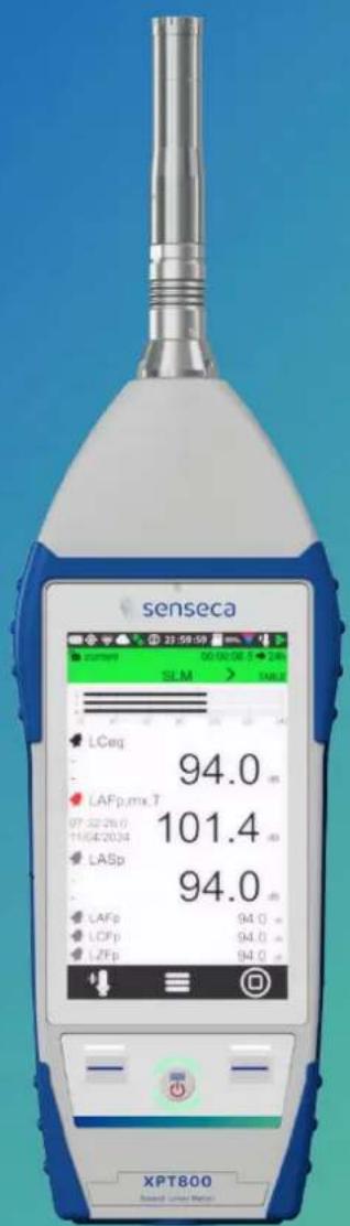
USER MANUAL XPT800 Senseca
Sound Level Meter and
Spectrum Analyzer
EN
V1.0

senseca
Contents
1 Information....6
1.1 General information....6
1.2 Safety information....7
2 Compliance and directives 9
3 Identification....11
3.1 Product identification.... 11
3.2 Part numbers of main components and accessories.... 11
3.3 Explanation of product code 11
4 Description of the instrument 12
4.1 Basic features.... 12
4.2 Possible applications.... 13
4.3 Main features 13
4.4 Performance characteristics.... 14
4.5 Instrument hardware overview.... 15
4.6 Description of main components 16
4.6.1 Microphone 16
4.6.2 Preamplifier 17
4.6.3 Instrument 17
4.6.4 Outdoor microphone unit (optional) 19
4.7 Display 20
4.7.1 Icon menu....21
4.7.2 Status Bar 22
4.7.3 Control Bar 24
4.7.4 Context menu 25
4.8 Navigation and selection.... 25
4.9 Keyboard....26
4.10 Entering text and numbers....26
5 Pre-use checks and operations 27
5.1 Unpacking and inspection.... 27
5.2 Standard configuration.... 27
5.3 Options and accessories....29
5.3.1 Hardware accessories....29
5.3.2 Hardware options.... 29
5.3.3 Firmware options.... 30
5.3.4 Software options.... 31
5.4 Assembling and disassembling components.... 32
5.4.1 Microphone and preamplifier 32
5.4.2 Windscreen.... 33
5.4.3 Outdoor microphone unit 33
5.4.4 Connect the outdoor microphone unit to the sound level meter 34
5.4.5 Mounting on a tripod 35
5.5 Battery power supply 35
5.5.1 Battery power use 35
5.5.2 Charging the battery.... 36
5.5.3 Battery insertion and replacement 37
5.6 External power supply 38
6 Switching on and off 39
6.1 Switching on 39
6.2 Display auto-off function 39
6.3 Switching off....40
7 Settings and Adjustments....41
7.1 Set current date and time....41
7.2 Using NTP server to synchronize date and time.... 42
7.3 Setting the language 42
7.4 Display adjustments 43
7.4.1 Adjusting the brightness.... 43
7.4.2 Setting the display auto power off 44
7.4.3 Selecting the display theme 44
7.4.4 Turning the TOUCH display on and off.... 45
8 Viewing modes....46
8.1 SLM mode....47
8.2 TABLE mode....48
8.3 Octave and Third Octave display (histogram).... 49
8.4 Time History display....51
9 Getting started: Main Functions....52
9.1 Calibration....52
9.2 Setting the duration of a measurement....53
9.3 Select acoustic parameters to be displayed.... 54
9.4 Set acoustic parameters to be stored....55
9.5 Subtraction of two acoustic parameters 58
9.6 Load a custom configuration....59
9.7 Set alarms on exceedances....60
9.8 Starting and stopping a measurement....62
9.9 Starting and stopping a measurement with datalogging....63
9.10 Recording an audio manually....64
9.11 Manually add markers to the measurement 65
10 Advanced functions....66
10.1 Setting the calibration parameters 66
10.1.1 Setup....66
10.1.2 Calibrations History....67
10.2 Setting triggers....68
10.3 Setting audio recording parameters....69
10.3.1 Audio recording mode....69
10.3.2 Audio recording resolution....70
10.3.3 Audio recording sampling frequency....70
10.3.4 Setting a duration limit to audio recordings....70
10.4 Custom measurement setups....71
10.4.1 "Current" Configuration....71
10.4.2 Load, Edit, Save as, Delete functions 71
10.4.3 "Lock" and "Auto-Load" attributes....73
10.5 Customizing markers 73
10.6 Continuous measurements datalogging....74
10.6.1 Recording Configuration....74
10.6.2 Continuous datalogging of Time History group 75
10.6.3 Continuous datalogging of Reports group 76
10.6.4 Datalogging of Events group 76
10.6.5 Recording Globals group 76
10.7 PLAYBACK and GENERATOR....77
10.7.1 PLAYBACK management....77
10.7.2 GENERATOR management.... 77
10.8 Activating the preamplifier heater....78
10.9 Monitor....79
11 Managing measurement data files....80
11.1 Setting the data file storage unit 80
11.1.1 Saving data to an external USB-C drive 80
11.2 Information on data file naming....81
11.2.1 Parameter Log_sequence = OFF 81
11.2.2 Parameter Log_sequence = ON* 81
11.3 Using the data file Archive 82
11.3.1 Visualization of data files....82
11.3.2 Manual cloud synchronisation of data files 83
11.3.3 Entering a voice note to the measurement 83
11.3.4 Renaming and deleting a data file 84
11.4 Saving of data files....84
11.4.1 Saving on PC 84
11.4.2 Data storage on Cloud 84
11.4.3 Automatic cloud synchronisation of data files via Push option 85
12 Network and connections....86
12.1 Network Settings....86
12.2 Connecting to a WiFi network....86
12.3 Connecting to an Ethernet port 88
12.4 Connecting through GSM network * 89
12.5 Connecting to a PC with USB interface 89
13 Firmware update and options 90
13.1 Firmware version....90
13.2 Firmware update....91
13.2.1 Wi-Fi firmware update....92
13.3 Instrument recovery via recovery firmware....93
13.4 Enabling or disabling options 93
14 Maintenance Operations....94
14.1 Cleaning the Instrument....94
14.2 Microphone cleaning (microphone diaphragm) 94
14.3 Accredited periodical calibration 94
15 Troubleshooting Guide....95
15.1 Formatting eMMC memory (FORMAT) 95
15.2 Restoring Parameters to Default Settings (Reset) 96
15.3 Malfunctions, causes and possible solutions....97
16 Long-term storage....99
17 Spare parts 100
18 Appendix A - Technical Specifications.... 101
19 Appendix B - Parameters.... 104
19.1 Measure Parameters....104
19.1.1 Parameters Classes....104
19.1.2 Composition of Acoustic parameters Labels 105
19.1.3 Classes of measurement parameters available for visualisation....106
19.1.4 Classes of measurement parameters available for storage....107
19.1.5 Types of parameters available for screens (views)....107
19.1.6 Types of parameters available for storage....108
19.2 Setup Parameters....108
20 Appendix C - Trigger.... 111
20.1 Exceedances settings....112
20.1.1 Exceedance of SLM parameters....112
20.1.2 Exceedance SLM mode (Exc_slm_mode)....113
20.1.3 Exceedance SLM thresholds (Exc_slm_threshold)....115
20.1.4 SLM exceedance duration filter (Exc_slm_duration)....115
20.1.5 Enabling SLM exceedances (Exc_slm_enable) 115
20.2 Setup trigger....115
20.2.1 Pre-trigger....115
20.2.2 Post-trigger duration....115
20.3 INPUT 116
20.3.1 SLM 116
20.3.2 MRK....116
20.3.3 MIX 116
20.4 Setting exceedances of a spectrum in octave or third octave bands 117
20.4.1 Enabling Spectrum exceedances....118
20.5 Trigger I/O Input....118
20.5.1 TRGOUT polarity ....118
20.5.2 TRIGIN polarity....118
20.5.3 TRGOUT Mode 118
21 Appendix D - File system information.... 119
21.1 XPT80X_SLM_Config....119
22 Declaration of Conformity 120
1 Information
1.1 General information
Properties of information
• Copyright © 2023, Senseca Italy Srl
• All rights reserved in all countries.
- Any distribution, modification, translation, or reproduction of parts or all of the document is prohibited unless authorized in writing by Senseca Italy Srl.
- Senseca Italy Srl reserves the right to make changes or corrections to the relevant documentation without prior notice.
- Data, figures and descriptions contained in the manual cannot be legally enforced.
- Requests for permissions, copies, or technical information regarding this manual should be addressed to:
Senseca Italy Srl - Via Marconi 5 - 35030 Selvazzano Dentro (PD) - ITALY
Phone +39 049 8977150 / email: info@senseca.com
Version info
Firmware
Fw: 0424_151
Fw metrology: 1.0
Fw GUI: 4_56
Fw Wi-Fi: 24_20
Use of the manual
Please read this manual carefully before using the instrument and keep all safety directions and instructions for future use.
- This instruction manual is an integral part of the instrument and should be kept throughout its life.
- It must be stored so that it is accessible to operators, in a clean place, and maintained in good condition.
- If the manual is lost or damaged, you can download the PDF version from www.senseca.com, on the model page in the product section.
- When transferring the instrument, always attach the instruction manual.
Symbols in the manual
To call the attention of users for the purpose of correct and safe use of the instrument, the following graphic symbols are adopted in this manual:

Info
To indicate particularly useful and important information in reading and understanding the manual.

Notice!
To signal a situation or practice that requires caution but does not directly cause personal injury or harm if ignored.

Warning!
To warn of dangerous situations that, if ignored, could cause injury or damage to the instrument.

Forbidden!
To signal the prohibition of an operation.

Observe the instructions!
To indicate that the instructions for use must be observed.
1.2 Safety information

Observe the instructions!
Read all safety instructions and directions.
- Failure to follow safety instructions and instructions may result in electric shock, fire and/or serious injury.
- Keep all safety directions and instructions for future use.

Notice!
- Upon receipt of the instrument, ensure the integrity of the delivery and, in case of non-conformity with what was ordered or damage to the instrument, promptly report the inconvenience to the carrier and the instrument supplier.
- Any adjustment, maintenance and repair of the equipment should be carried out only by trained service.
- Any contractual and extra-contractual liability of the Manufacturer for damage caused to persons, animals or property, from adjustment, maintenance errors and improper use is excluded.
- If you have any doubts regarding the condition and/or functionality of the instrument and attached parts, please contact Senseca Italy Srl.

Warning!
- During the first use of the instrument report, to the instrument supplier, any anomalies or malfunctions found.
- Use only original or Manufacturer-approved spare parts to avoid possible damage to the instrument.
- Do not remove any safety signs, stickers or labels from the instrument. Keep safety signs, stickers, or labels in good condition so that they can be read well.

Warning!
Explosion Hazard:
The device is not designed for use in potentially explosive environments. It should not be operated in the presence of flammable liquids or gases.

Forbidden!
It is forbidden to use the instrument improperly. In particular:
- Do not use the instrument in explosive environments or areas and in aggressive, corrosive atmospheres with oil-containing vapors.
- Do not use the instrument in the presence of flammable liquids or gases.
- Do not allow liquids to penetrate inside the instrument.
- Avoid condensation on the membrane, as it substantially alters its acoustic response, leads to corrosive phenomena and contributes to the formation of residues that are difficult to remove. In case of exposure of the microphone chain to weather, use outdoor protection systems.
- Avoid even minor impacts to the microphone capsule.
- Do not expose the instrument to strong vibration.

Forbidden!
It is forbidden to make changes and/or attempts to repair the instrument. In particular:
- Making changes, causes the instrument's Declaration of Conformity to lapse.
- For damage resulting from improper use, the user is solely responsible. Any repairs must be carried out by a qualified technician.

Forbidden!
- Children and persons with reduced abilities or lack of specific experience and knowledge are prohibited from using the instrument unless they are assisted by qualified personnel responsible for their safety.
- It is forbidden for children to play with the instrument.
- It is forbidden to disperse packaging material into the environment and leave it within the reach of children as it can be a potential source of danger. It must therefore be disposed of in accordance with current legislation.
2 Compliance and directives
Acoustical Directives
The product meets the following class 1 specifications.
Sound Level Meter:
• IEC 61672-1 (2013) class 1
• IEC 60651 (1979) plus amendment 1 (1993-02) and amendment 2 (2000-10), type 1
• IEC 60804 (2000-10) type 1
• ANSI S1.4-1983 plus ANSI S1.4A-1985 amendment type 1 (sound level meter)
• ANSI/ASA S1.4-2014 class 1
• ANSI S1.43-1997 type 1
Octave band and fractional octave filters:
• IEC 61260-1 (2014)
• ANSI/ASA S1.11-2014 Part 1
Homologation in accordance with IEC 61672-1 (2013) and IEC 61260 (2014) is pending.
IEEE 802.11 (Wi-Fi) certifications:
XPT80X sound level meters contain IEEE 802.11b/g/n certified RF module.
FCC ID: QOQWGM160P IC
ID: 5123A-WGM160P
KC: R-C-BGT-WGM160P
TELEC: [R] 005-102265

005-102265
FCC and IC notices
Notice: This device complies with Part 15 -15.247(a2) and 15.247(b) and 15.249 of the FCC Rules and with Industry Canada (IC) licence-exempt RSS standard(s). Operation is subject to the following two conditions: (1) this device may not cause harmful interference, and (2) this device must accept any interference received, including interference that may cause undesired operation.
Notice: This equipment has been tested and found to comply with the limits for Class B digital device, pursuant to part 15 of the FCC Rules. These limits are designed to provide reasonable protection against harmful interference in a residential installation. This equipment generates, uses and radiates radio frequency energy, and, if not installed and used in accordance with the instructions, may cause harmful interference to radio communications. However, there is no guarantee that interference will not occur in a particular installation. If this equipment does cause harmful interference to radio or television reception, which can be determined by turning the equipment off and on, the user is encouraged to try to correct the interference by one or more of the following measures:
- Reorient or relocate the receiving antenna.
- Increase the separation between the equipment and receiver.
- Connect the equipment into an outlet on a circuit different from that to which the receiver is connected.
- Consult the dealer or an experienced radio/TV technician for help.
Notice: To satisfy FCC/IC RF exposure requirements for mobile and base station transmission devices, a separation distance of 20 cm or more should be maintained between the antenna of this device and persons during operation. To ensure compliance, operation at closer than this distance is not recommended. The antenna(s) used for this transmitter must not be co-located or operating in conjunction with any other antenna or transmitter.
Notice: Under Industry Canada regulations, this radio transmitter may only operate using an antenna of a type and maximum (or lesser) gain approved for the transmitter by Industry Canada. To reduce potential radio interference to other users, the antenna type and its gain should be so chosen that the equivalent isotropically radiated power (e.i.r.p.) is not more than that necessary for successful communication.
3 Identification
3.1 Product identification
- The serial number is printed on the label on the back panel.
- The microphone model and serial numbers are engraved on the outside of the microphone.
- The preamplifier model and serial numbers are engraved on the outside surface of the preamplifier.
Information regarding product identification can be found by accessing the page SETTINGS > INSTRUMENT > IDENTIFICATION.
3.2 Part numbers of main components and accessories
The following are the codes of the main components and accessories mentioned in the manual and related to the use of the XPT800 model.
| Code | Description |
| XPT800 | Sound Level Meter |
| MP800 | Single range microphone preamplifier |
| MC800 | Precision microphone |
| WS90 | 90 mm Windscreen |
| WSO | Outdoor microphone protection |
| WSO-C | Outdoor microphone protection with built-in acoustic calibration system controlled by XPT800 |
| NS-ENS | Data processing software module |
| CPL-4.5 | 5 m microphone extension cable |
| CPL-4.10 | 10 m microphone extension cable |
| HD2020 | Class 1 acoustic calibrator, 94-114 dB. Frequency 1 kHz |
Firmware and hardware options are covered in the section "5.3 Options and accessories" on page 29.
3.3 Explanation of product code
| Code | Description |
| XPT800 | XPT: indicates the product line 1^st number: Leading Group (8=Sound & Vibration) 2^nd number: Subunit (0=Sound Pressure Levels) 3^rd number: level of functionality (0= higher level)Any other numbers separated by a space may be present and follow the three-number code to indicate additional product features (e.g., number of channels or other information) |
As for option codes these are preceded by a letter F if it is a firmware option or letter H if it is a Hardware option. They are always preceded by the code for the instrument to which they refer e.g. XPT800-OF1E refers to an option of the XPT800 model, Firmware Option.
4 Description of the instrument
XPT800 is a class 1 sound level meter-spectrum analyzer.
It is based on a scalable platform that can be adapted to the growing needs of acoustic professionals. The needs for accuracy, high performance, and ease of use have been met through the use of the latest technology and careful consideration of suggestions from experts in the field. Top quality and performance to provide the acoustics specialist with a comprehensive and reliable tool for all major applications in the field, from environmental noise and building acoustics to risk assessment in work environments and laboratory and industrial product analysis.
4.1 Basic features
XPT800 performs the following basic operations:
- Sound measurement: stop, pause and resume measurement of instantaneous and integrated parameters.
- Fine-tune the measurement using a precision acoustic calibrator and archive the calibration history.
- Back-erase: upon operator command, backwards erases for a selectable time interval, data of unwanted sound events, excluding them from calculations of integrated values shown on display.
- Reset: resets, upon operator command, the integrated values shown on the display.
- Time recorder for single event metrics Lmax, Lmin, Lpeak-(max).
- Displays broadband and spectral sound values on a color screen.
- Displays real-time and stored data while a measurement is in progress.
- Allows you to freely select and change, even with measurement in progress, the displayed measurement parameters independently of the stored measurement parameters.
- Displays data in numerical and graphical form.
- Record audio signal with manual control or by automatic level trigger.
- Simultaneously records the time instant of measurement samples and sound events.
- Perform statistical analysis of broadband or spectral parameters.
- Use of manual or automatic markers to annotate portions of time tracks referable to specific sound events.
- Enter voice annotations related to the measurement.
- Continuous data storage on both internal and external high-capacity storage media.
- Connecting to a network through Wi-Fi, Ethernet, GSM devices.
• Diagnosis of proper hardware operation.
- Firmware update.
- Provides location via built-in GPS.
- Synchronizes the watch with PC, GPS or Network Time Protocol (NTP).
- Create multiple custom configurations using APPLICATIONS.
• View data in the measurement archive.
• Mass storage to be used mmc μSD, USB stick.
- Recharges internal high-capacity batteries.
- Allows the use of alternative microphone chains to the standard chain and is compatible with both 200V-polarized and pre-polarized microphones.
- Handles preamplifiers equipped with internal heater for outdoor uses.
- Allows outdoor measurements using specific outdoor protection accessories.
Note: features may be related to specific firmware and hardware functions.

Info
For the complete list of operations that XPT800 can perform, see the section "10 Advanced functions" on page 66.
4.2 Possible applications
XPT800 is suitable for the following applications:
• Assessment of environmental noise levels (DM 16/03/98, ISO1996).
- Noise monitoring with sound event capture and analysis function.
• Spectral analysis for octave bands and third octave bands.
- Complete statistical analysis with calculation of all percentiles from L0.1 to L99.9.
• Measurements in workplace environment (ISO9612).
• Soundproofing and noise remediation.
• Manufacturing quality control.
• Measurement of machine noise.
• Building Acoustics (ISO16283).
- Speech intelligibility.
- Noise criteria
• Triaxial Vibrations (ISO2631/ISO5349).
Note: Some features are expected but may not be available immediately but only successively after the product is released to the market. Please contact the Senseca Italy Srl sales office for more information.
XPT800 can be supplemented with additional options to extend its scope when needed; firmware can be upgraded directly by the user.

Info
For the complete list of available additional options, see the chapter "5.3 Options and accessories" on page 29.
4.3 Main features
• Large 4.3" color touch screen display.
• Memory: internal 4GB on eMMC and external USB-C stick. μSD memory up to 64GB (TBA).
• Ergonomic design for one-hand operation.
- Rugged body design for use in harsh environments.
- User interface: intuitive user interaction using smartphone-like gestures; ability to manage functionality even using the 3-button keyboard.
- Wireless connectivity: data transfer and remote control of the instrument.
- Internal interfaces: Wi-Fi, 4G, LAN, USB-C, RS232/485.
- Long-lasting battery life: internal rechargeable battery allows more than 24 hours of measurement time.
• Triaxial input for vibration sensors (TBA).
- "Noise Studio Web storage" (https://noise-studio.senseca.com/) web application: recorded data storage functions.
- "Noise Studio Web Monitor" web application: management functions of one or more devices remotely or locally.
- NS-ENS “Environmental Noise Studio” desktop application: analysis of noise measurements and intelligent reporting tools for increased productivity.
- NS-SIS “Sound Insulation Studio” desktop application: analysis of passive acoustic requirements of buildings.

Info
For the complete list of features of the XPT800 instrument, please refer to the section "18 Appendix A – Technical Specifications" on page 101.
4.4 Performance characteristics
- Interchangeable microphone chains with automatic identification (digital sensor interface).
• Accuracy: class 1 according to IEC61672:2013.
• Single measurement interval: 20-140.
• Dynamic range: higher than 125 dB.
• Frequency weightings A, B, C, Z.
• Linear, exponential and moving averages. - Simultaneous time constants Fast, Slow, Pulse, Peak.
• Audio recording: manual or automatic up to 32bit - 48KHz. - Spectral analysis: real time 1/1 - 1/3 oct.; interval 6.3 Hz-20 kHz (IEC 61260).
• Statistical analysis: Ln broadband and 1/3 oct. band levels.
• Automatic detectors of tonal and impulsive characteristics of sound.
4.5 Instrument hardware overview
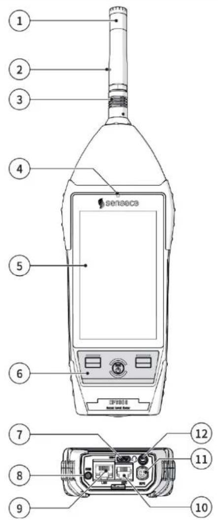
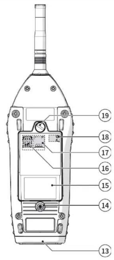
Fig. 1 - Hardware overview
1 Microphone capsule
2 Preamplifier
3 Push & pull connector
4 Light sensor
5 Display
6 Keyboard
7 USB-C
8 GSM antenna connector (opt. OH3M)
9 LAN socket (opt. OH3B): RJ45 type connector
10 AUX connector (opt.OH3B): RJ12-type connector, for connection to external devices, e.g., a weather controller
11 IEPE type push & pull connector (opt.OH3B): for connection to a triaxial accelerometer for vibration measurement
12 Connector for audio output / filtered AC output / trigger I/O: ∅ 3.5 mm jack socket
13 Rubber protection for connectors
14 1/4" threaded hole for fixing stand
15 Battery compartment
16 SIM slot
17 Micro-SD card slot
18 Battery connection
19 Battery compartment opening/closing screw
4.6 Description of main components
flowchart
graph TD
    A["Microphone"] --> B["Preamplifier"]
    B --> C["ID"]
    B --> D["CIC"]
    B --> E["HEATER"]
    C --> F["Cable"]
    D --> F
    E --> F
    F --> G["XPT800"]
    G --> H["CPU"]
    H --> I["A/D"]
    H --> J["USB"]
    H --> K["Power management"]
    K --> L["Lithium battery"]
    H --> M["Playback TRGIO"]
    H --> N["eMMC"]
    H --> O["uSD"]
    H --> P["TFT display"]
    H --> Q["Status LED"]
    H --> R["Keypad"]
    H --> S["Monitor module"]
    S --> T["A/D"]
    S --> U["A/D"]
    S --> V["A/D"]
    S --> W["A/D"]
    T --> X["5V"]
    T --> Y["9-24V"]
    U --> Z["ACC"]
    V --> AA["Ethernet"]
    V --> AB["Aux RS232/485"]
    X --> AC["4G"]
    Y --> AD["4G module"]
    Z --> AE["A/B"]
    AA --> AF["A/B"]
    AB --> AG["A/B"]
    AC --> AH["TFT display"]
    AD --> AI["GPS"]
    AE --> AJ["SIM"]
    AF --> AK["USB"]
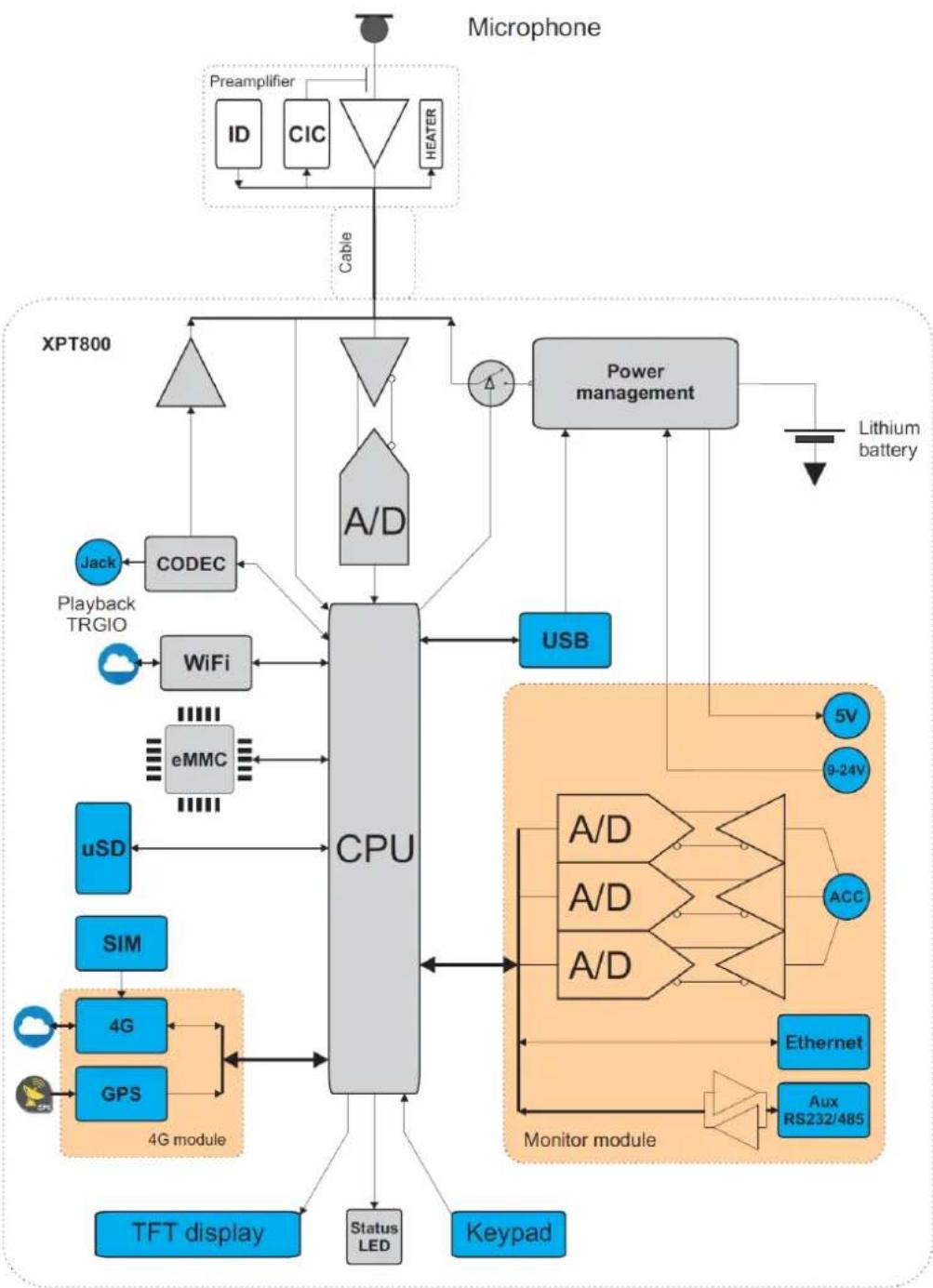
Fig. 2 - Block diagram
4.6.1 Microphone
The supplied MC800 microphone is of the pre-polarized condenser type, with 1/2" standard diameter and has a nominal sensitivity of 50 mV/Pa. With this microphone, the free-field frequency response is flat over the entire audio range, and the maximum measurable sound level of the XPT800 is 140 dB.
The MC800 microphone meets the requirements of the international standard IEC 61094-4 for type WS2F. Optionally, other microphone types can be mounted.
For more details regarding the technical specifications of the microphones that can be combined with the XPT800 sound level meter, please consult the relevant manuals or contact the Manufacturer.
4.6.2 Preamplifier
The MP800 preamplifier performs the task of amplifying the weak signal provided by the microphone. The peculiar dynamic performance combined with low noise enables the detection of both very low and high level sound signals using a single measurement range. The MP800 preamplifier is also equipped with a CTC (Capacitive Transducer Calibration) calibration device, which allows the drifts of the entire measurement chain, including the microphone, to be kept under control by means of a charge-sharing scheme.
Available models are listed in chapters “5.2 Standard configuration” on page 27 and “5.3 Options and accessories” on page 29.
Heater
The MP800 preamplifier is equipped with an internal heater, which can be activated from the GUI. Use of the heater is recommended to reduce condensation on transduction chain components in outdoor uses with high humidity levels and low temperatures.
Automatic detection
A chip inside the preamplifier stores certain information about the transduction chain (e.g., the pre-amplifier serial number) that is automatically detected by the XPT800 sound level meter, allowing the user to use different transduction chains without the need for setting operations.
4.6.3 Instrument
The signal from the preamplifier reaches the input of the A/D converter. The analog signal is converted into numerical form by the A/D. The exceptional resolution of the converter, which extends over a range of more than 140 dB, allows high accuracy to be maintained over a single measurement range of about 125 dB where digitization error is negligible. In the DSP, levels with broadband frequency weightings (A, B, C, and Z) and levels with both octave and third-octave constant percentage bandwidth weightings are calculated in parallel. Peak levels are also calculated. The levels calculated by the DSP are transmitted to the microprocessor for further processing, display, storage.
The microprocessor supervises all instrument processes: management of the electrical calibrator, memory, TFT touch display, keyboard, network and communication devices (LAN, Wi-Fi, 4G), GPS, codec, and interfaces (RS232C and USB).
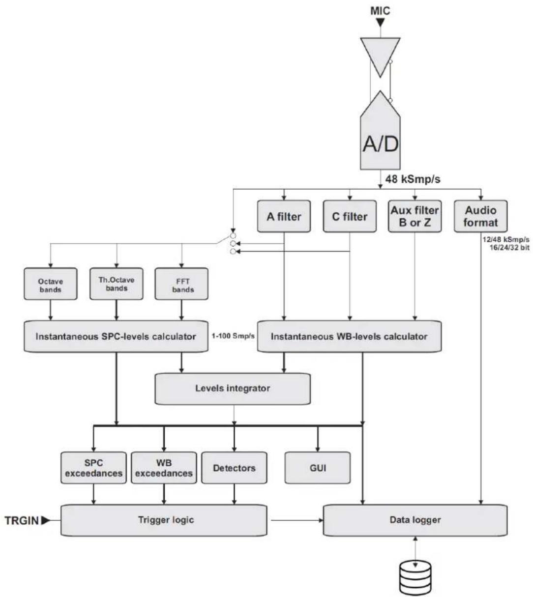
flowchart
graph TD
    A["MIC"] --> B["A/D"]
    B --> C["48 kSmp/s"]
    C --> D["A filter"]
    C --> E["C filter"]
    C --> F["Aux filter B or Z"]
    C --> G["Audio format"]
    D --> H["Instantaneous SPC-levels calculator"]
    E --> I["Instantaneous WB-levels calculator"]
    F --> I
    G --> J["Levels integrator"]
    H --> K["Octave bands"]
    H --> L["Th.Octave bands"]
    H --> M["FFT bands"]
    I --> N["1-100 Smp/s"]
    J --> O["Levels integrator"]
    K --> P["SPC exceedances"]
    L --> Q["WB exceedances"]
    M --> R["Detectors"]
    N --> S["Trigger logic"]
    O --> T["Data logger"]
    P --> U["TRGIN"]
    Q --> U
    R --> U
    T --> U
    U --> V["Data logger"]
    style A fill:#f9f,stroke:#333
    style B fill:#ccf,stroke:#333
Fig. 3 - Analysis process
4.6.4 Outdoor microphone unit (optional)

Info
For more information, see the outdoor microphone unit manual provided with the unit.
The WSO microphone unit is suitable for prolonged time surveys in outdoor environments, including unattended fixed locations. The unit is adequately protected from rain and wind, and the heated pre-amplifier provides stability of acoustic parameters over time and allows surveys in a wide range of environmental conditions.
The preamplifier of Senseca sound level meters, coupled with the outdoor microphone unit, is equipped with a circuit for electrical calibration of the preamplifier-microphone capsule chain, which uses a charge-sharing technique.
The unit free-field frequency response meets class 1 specifications according to IEC 61672 (and IEC60651).
The WSO microphone unit must always be placed vertically to allow the rain shield to perform its function and can be used to detect both airborne and ground-borne noise. Senseca sound level meters make spectral corrections to measurements to ensure class 1 tolerances according to IEC61672 in every situation.
The easy disassembly and reassembly of the unit allows periodic verification of electroacoustic characteristics to be carried out in the same way as with a standard measuring microphone, using a standard 12 " microphone calibrator.
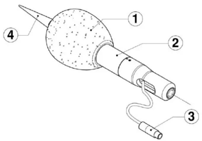
Fig. 4 - WSO outdoor microphone unit
1 Windscreen
3 Microphone connector
2 Stainless steel support
4 Bird spike
Note: For more details on using the outdoor unit, see chapters "5.4.3 Outdoor microphone unit" on page 33, "5.4.4 Connect the outdoor microphone unit to the sound level meter" on page 34 and "9.1 Calibration" on page 52.
4.7 Display
XPT800 is equipped with a color backlit TFT touchscreen with sunlight adaptability. For the full list of display features, see the section "18 Appendix A – Appendix A – Technical Specifications" on page 101.
The interface of the XPT800 is organized into status and control bars, and menus, the latter further organized into panels that can be accessed using navigation icons/keys.
When XPT800 is turned on, the instrument displays the Home page, containing elements common to most screens.
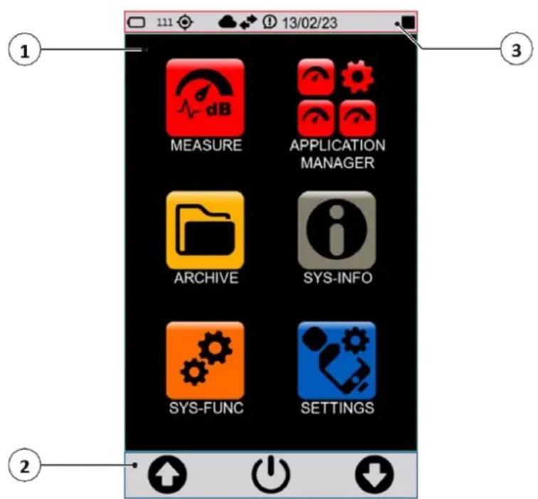
Fig. 5 - Home page
1 Home Page (Icon Menu)
2 Control bar
3 Status bar

Info
You can adjust some display settings, such as brightness and auto power off: see the section "7 Settings and Adjustments" on page 41.
4.7.1 Icon menu
The main screen of the instrument is called ICON MENU and is the access screen for the main features of the instrument represented by icons.
The icon has 2 states:
- inactive: the application is currently unavailable and is represented in shaded color; touch or keyboard have no effect.
- active: the application is available for execution and is represented normally; touch or keyboard runs the application.
The icon menu can be accessed, even during measurements, by holding down the center icon (MENU) on the control bar for a few seconds.
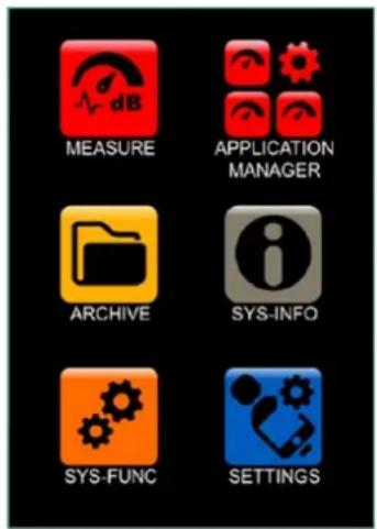
Fig. 6 - Icon menu
The basic applications of the instrument are described in the following table.
Table 1 - Icon menu
| Action | Icon | Description |
| MEASUREMENT |  | Allows direct access to the measurement panel based on the settings of a setup of the user's choice |
| APPLICATION MANAGER |  | Allows access to panel for selection and management of custom measurement apps |
| ARCHIVE |  | Allows access to the panel for managing stored measurements |
| SYS-INFO |  | Allows access to the system information and monitor menus |
| SYS-FUNC |  | Allows access to system app menus |
| SETTINGS |  | Allows setting the working parameters of the instrument. Allows setting of all measurement parameters and control of all hardware and computational functions of the instrument. Frequently used parameters can also be accessed directly from the measurement screen. |
4.7.2 Status Bar
The status bar describes through icons the status of the instrument, power, connectivity and measurement status. It also provides access to the activation keys.
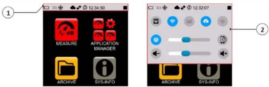
Fig. 7 - Status bar
1 Status icons: indicate the mode and operation status of the instrument
2 Activation icons: activated with blue color, deactivated with gray color
Status icons
| Icon | Description | Icon | Description | Icon | Description |
| Writing to eMMC | Writing to USB key | Writing to μSD (TBA) | |||
 | Access to "Cloud Storage service" occurred |  | Cloud active but access to "Cloud storage service" not occurred |  | Access to "Cloud Manager service" occurred |
| Access to "Cloud Monitor service" occurred | Synchronization queue (black arrows) | Synchronization active (green arrows) | |||
 | Measurement with recording | [SKA2] | Pause | [0648] | Stop |
| Measurement | Audio recording | Notification | |||
| Indication of overload in progress | Overload memory | Below acoustic threshold | |||
| LAN | Wi-Fi | Modem | |||
| GPS | Battery | 99% | % available memory of the memory support used |
Activation keys
With functionality available, the activation buttons appear in gray color with the symbol in white color. At the time the functionality is activated, the icon appears in blue color. In case the functionality is not available (e.g. 4G hardware not present), the corresponding icon appears present but inactive, with the symbol in gray color.
Example of activating/deactivating modem functionality:

Functionality available

Functionality NOT available

Functionality activated
| Icon | Description | Icon | Description | Icon | Description |
 | Wi-Fi activated |  | Cloud transfer activated (1) |  | GPS activated |
 | Display shut-off timer |  | Modem activated |  | Automatic brightness adjustment |
 | Ethernet activated |  | Increase volume |  | Decrease volume |
 | Adjusting slider |
(1) The key turns on/off the parameter Log synchronization. If active and if there are files available to synchronize, the status icon will indicate synchronization.
4.7.3 Control Bar
It allows the user context control and access to related menus. The bar contains three symbols possibly accompanied or replaced by text to indicate three possible actions that the user can perform either by the corresponding key or by touch. A long press of the ENTER key takes the user back to the icon menu.
The content of the bar depends on the context, level, and related status:
- CONTEXT: refers to the running application, e.g., Measure, Archive, Sys-info, etc.;
- LEVEL: in the specific context refers to a specific action;
- STATUS: follows the progress of a specific action.
Table 2 - Control bar icons
| Icon | Description | |
| Icon menu controlUp/down arrows: icon selectionON/OFF icon: access to the OFF panel (press 3 seconds) | ||
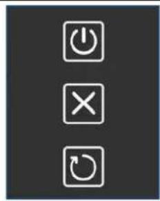 | OFF panelPress the ON/OFF button for 3 seconds to activate it.Upper icon: turns off the instrumentMiddle icon: cancels the operation and closes the panel OFFLower icon: restarts the instrument | |
 | Measurement controlLeft icon: start measurement without recordingRight icon: start measurement with recording (Log)Central icon (MENU): access to the context menu | |
 | With measurement started:Left icon: pauseRight icon: stopCentral icon (MENU): access to the context menu | |
 | With measurement started and pause button pressed:Left icon: pause releaseRight icon: resetCentral icon: back-erase | |
 | With recording (Log) started:Left icon: manual audio recordingRight icon: stop recordingCentral icon (MENU): access to the context menu | |
 | Navigation/function managementArrows (UP/DOWN): allow you to navigate through the available functionsCentral icon (OK): enter the menu | |
 | Middle icon (EXIT): exit the menu | |
 | Central icon (FILTER): allows you to set search filters | |
4.7.4 Context menu
Once the measurement panel (MEASURE) has been accessed, the context menu is available in the control bar. The various functions also available during measurement and recording are shown below.
Table 3 - Context menu
| Icon | Description |
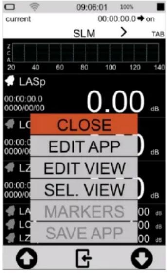 | CLOSECloses the context menuEDIT APPSet the recording parameters, see “9.4 Set acoustic parameters to be stored” on page 55.EDIT VIEWSelect the parameters visible during the measurement, see “9.3 Select acoustic parameters to be displayed” on page 54.SEL. VIEWChange the display mode, see “8 Viewing modes” on page 46.MARKERS (active only during a measurement)Set markers, see “9.11 Manually add markers to the measurement” on page 65.SAVE APPStores current settings |
4.8 Navigation and selection
To navigate within the functions of the instrument, press on the desired item or icon on the touchscreen display or press on the navigation icons on the control bar.
See the chapter "4.7 Display" on page 20 for the complete list of icons in the display and their function.

Info
To quickly exit any screen and return directly to the home page, simply press and hold down for as long as necessary the center icon of the control bar, whatever it is.
4.9 Keyboard
The keyboard has a waterproof backlit membrane. There are two function keys with white LED backlighting and an ON/OFF/ENTER key with custom-shaped RGB backlighting.
The keys on the keypad have the same functions as the corresponding icon on the control bar, for a detailed explanation of the functions see the section "4.7.3 Control Bar" on page 24.
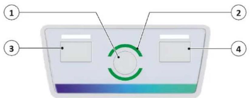
Fig. 8 - Keyboard overview
1 ON/OFF/ENTER key emulates the central icon of the control bar
ON/OFF function: pressed briefly turns the instrument on
ENTER function
2 RGB status LED
3 LEFT key (White LED): emulates the left icon of the control bar
4 RIGHT key (White LED): emulates the right icon of the control bar
4.10 Entering text and numbers
XPT800 has a virtual keyboard that is displayed when selecting a field in which text is to be entered. The virtual keyboard allows entry of character strings such as letters and numbers.
The instrument also has a numeric keypad for entering both integer and floating-point numeric values.
The following is an example of text input.
| 1 Press in the text input field.2 The virtual keyboard is displayed.3 3 Press on the keys to enter the desired text.4 Press te confirm, press to cancel the operation. | a b c d e f g h i j k l m n o p q r s t u v w x y↑ z , .123 ← X |
5 Pre-use checks and operations
5.1 Unpacking and inspection
- XPT800 is shipped in a protective packaging.
- Immediately report any damage to the instrument packaging to the transporter and instrument supplier.
- Verify that the shipment contains all parts and accessories for the selected configuration, see chapter "5.2 Standard configuration" on page 27.
- Verify that all purchased options are active in SYS-INFO/ FIRMWARE/OPTIONS.
- Save the packaging for possible safe shipment to the service department.

Info
The quality level of our instruments is the result of continuous development of the instrument. This can lead to differences in the parts and accessories listed in the standard configuration and the parts that make up the instrument you have purchased. We recommend that you check with what you have ordered.
5.2 Standard configuration
XPT800 is available as part of an integrated system or in a standard configuration. The following components are supplied with the standard configuration:
| Component | |
| XPT800 Sound Level Meter | 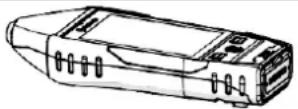 |
| MP800 preamplifier | 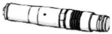 |
| MC800 microphone |  |
| WS90 windscreen |  |
| Certificate of Conformity | |
| Free access to cloud storage space | |
| Standard hard carrying case BAG8• airtight seal• automatic pressurization valve• safety locks with push button• padlock predisposition• shoulder belt predisposition• lightweight and impact-resistant body• preformed sponge for positioning sound level meter, wind-screen and accessories | 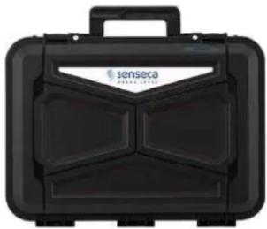 335 x 295 x 122 mm 335 x 295 x 122 mm |
The following hardware and firmware options are included with the standard configuration:
| Hardware options | Description | Code |
| Basic | Sound level meter, carrying case, WS90 windscreen, USB-C cable, conformity certificate | XPT800 |
| OH1 | MC800 microphone (50mV/Pa) + MP800 preamplifier set | XPT800-OH1 |
| OH4 | Outdoor measurements: CIC management, preamplifier heater power supply | XPT800-OH4 |
| OH5 | Measurements with sound source controlled by the instrument (STI, Reverber-ation, etc.) | XPT800-OH5 |
| Firmware options | Description | Code |
| OF3 | Statistic Analyzer:- user Ln (wideband level)- Probability and cumulative probability distribution (wideband levels) | XPT800-OF3 |
| OF5S | Measurement data synchronization on NS-Storage cloud service (Push)- Manual- Automatic | XPT800-OF5S |
| OF8A | Event detector:- User programmable exceedances- User programmable third octave spectrum window acceptance (with OF1E options)- EVENT profile recording trigger logic- AUDIO recording trigger logic (with OF4 option) | XPT800-OF8A |
| OF8B | Fast data logging:- History profiles down to 10ms sampling interval | XPT800-OF8B |
| OF8C | Moving average calculations:- wideband levels- octave band levels (with OF1AE options)- third-octave band levels (with OF1E options)- wideband percentile levels | XPT800-OF8C |
| OF8D | Noise Assessment Period Levels:- Ldn, Lden, Lday, Levening, Lnight | XPT800-OF8D |
| OF13A | Datalogger:- HISTORY profiles from 100 ms to 1 s step- GLOBALS recording | XPT800-OF13A |
| OF13B | Advanced datalogger:- HISTORY profiles from 100 ms to 1 s step- REPORTS profiles from 10 s to 1 h step- EVENTS profiles- GLOBALS recording | XPT800-OF13B |
| OF15 | Extended dynamic range:- >35-bit measurement resolution- 0.01 dB resolution on 143 dB measurement range- 120 dB linearity range according to IEC 61672 | XPT800-OF15 |
5.3 Options and accessories
5.3.1 Hardware accessories
The table below contains only a few examples of the available hardware accessories. Additional components include, but are not limited to, microphones, preamplifiers, software, power supplies, tripods, calibrators, sensors, protective cases, adapters, and cables.
For a complete list of standard and system accessories, see website www.senseca.com.
The following components can be supplied in addition to the standard configuration:
| Component | |
| HD2020 acoustic calibrator cl.1 IEC 60942, 94/114 dB @1 kHz | 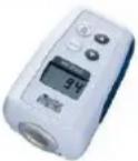 |
| WSO Outdoor microphone unit | 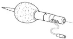 |
| WSO-C Outdoor microphone unit with built-in sound source | 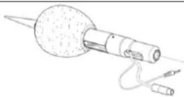 |
| Microphone extension cable (standard length 5 m, other lengths available upon request) | |
| Large hard carrying case BAG8K(Supplied in conjunction with sound level meter and acoustic calibrator kit)• airtight seal• automatic pressurization valve• safety locks with push button• padlock predisposition• shoulder belt predisposition• lightweight and impact-resistant body• preformed sponge for positioning sound level meter, wind-screen and accessories | 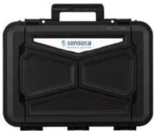 465 x 355 x 145 mm 465 x 355 x 145 mm |
5.3.2 Hardware options
| Hardware options | Description | Code |
| OH3B | Monitor module with triaxial accelerometer input:RS232/485 interfaceexternal power supply 9 V-24 V9 V-24 V battery charging5 V 500 mA output for external accessories power supplyEthernet connection4-pin push & pull connector for tri-axial accelerometer (vibration mode TBA) | XPT800-OH3B |
| OH3M | Network module with 4G modem and GPS (needs OH3B) | XPT800-OH3M |

Info
Installation of hardware options is the responsibility of the Manufacturer, so you must return the instrument to perform the installation.
5.3.3 Firmware options
| Firmware options | Description | Code |
| OF1E | Spectrum analyzer:IEC 61260 octave bands from 8 Hz to 16 kHzIEC 61260 third-octave bands from 6.3 Hz to 20 kHzReal time operation from 6.3 Hz to 20 kHz according to IEC 61260Latency equalized filters for transient analysis | XPT800-OF1E |
| OF1AE | Spectrum analyzer:IEC 61260 octave bands from 8 Hz to 16 kHzReal time operation from 8 Hz to 16 kHz according to IEC 61260Latency equalized filters for transient analysis | XPT800-OF1AE |
| OF2 | FFT Spectrum analyzer | XPT800-OF2 |
| OF3S | Advanced Statistic Analyzer (needs OF1E):calculation of sliding percentile levelsmeasurement of 7 user selectable percentiles of third-octave band levelsprobability and cumulative probability distribution of third octave band levels | XPT800-OF3S |
| OF4 | Audio recording (Manual, Automatic):16-bit, 24-bit or 32-bit resolution12 kSmp/s or 48 kSmp/s sampling rateWAVE or ADPCM format | XPT800-OF4 |
| OF5A | NS-Monitor service for local and remote instrument management | XPT800-OF5A |
| OF6 | STI calculation with STIPA method (needs OF1AE or OF1E options) | XPT800-OF6 |
| OF9 | Noise Ratings NC, RNC, NR, RC (needs OF1E or OF1AE) | XPT800-OF9 |
| OF10A | Triaxial vibration measurement (needs OH3B module)- ISO 5349 human exposure to hand-transmitted vibration- ISO 2631-1 human exposure to whole-body vibration | XPT800-OF10A |
| OF10B | Triaxial vibration measurement (needs OH3B module)- ISO 2631-2 human exposure to whole-body vibration in buildings | XPT800-OF10B |
| OF11A | Automatic Detectors-Tonality detector ISO1996 (with OF1E option) | XPT800-OF11A |
| OF11B | Automatic Detectors (DM16/03/98)- Tonality detector (with OF1E option)- Impulse detector | XPT800-OF11B |
| OF12 | Reverberation time calculation (T60)- Interrupted noise source-integrated impulse response | XPT800-OF12 |
| OF13M | Weather parameters datalogger (OH3B option needed)- Weather station interface-HISTORY profiles of weather data | XPT800-OF13M |

Info
Firmware options are installable by activation code after purchase. Refer to the chapter "13.4 Enabling or disabling options" on page 93.
5.3.4 Software options
| Software options | Description | Code |
| NS-Storage | NS-Storage cloud service:- Measurement data archive- Measurement data view: graphics, tables- Synchronization API- Limited storage space | Included |
| NS-Monitor | NS-Monitor cloud service:- Measurement control- Measurement setup- Real-time view of instrument measurements | Activated via XPT800-OF5A |
| NS-ENS | Environmental Noise Studio: desktop software module for advanced environmental noise analysis. Compatible with Windows OS (min. Windows10) | NS-ENS |
| NS-SIS | Sound Insulation Studio: desktop software module for advanced building acoustics analysis. Compatible with Windows OS (min. Windows10) | NS-SIS |

Info
Software options are installable by activation code after purchase.
5.4 Assembling and disassembling components
5.4.1 Microphone and preamplifier

Warning!
Observe the following instructions when assembling and disassembling the microphon and preamplifier:
- Connect to ground so that the device is not exposed to static shock.
- Clean from any dust or debris.

Forbidden!
During the assembly and disassembly of the microphone and preamplifier:
- Avoid even minor shocks: the microphone may be damaged.
- Never use excessive force or screw too hard.
- Do not remove the microphone grid cap and expose the diaphragm.
- Do not unscrew the microphone unless strictly necessary.
- Do not use glue to screw in the microphone.
To connect the microphone and preamplifier.:
The body of the preamplifier houses a single gold-plated stud with threading on the top edge, designed to fit the 12 " microphone and a "push & pull" coupling for connection to the sound level meter.
1 Carefully place the bottom of the microphone over the top of the preamplifier and gently screw the assembly on. The body of the microphone should fit snugly against the body of the preamplifier.
2 Place the preamplifier in line with the sound level meter pins and with the red mark toward the front of the sound level meter. Insert the preamplifier firmly into the sound level meter until you hear a small click.
To disconnect the microphone and preamplifier.:
1 Gently grasp the microphone on the two etched lines and unscrew it.
2 Grasp the preamplifier firmly with one hand, with two fingers pull the ferrule outward until the pre-amplifier disconnects.
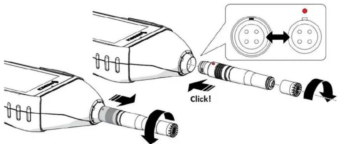
Fig. 9 - Connecting/disconnecting the microphone and preamplifier
5.4.2 Windscreen
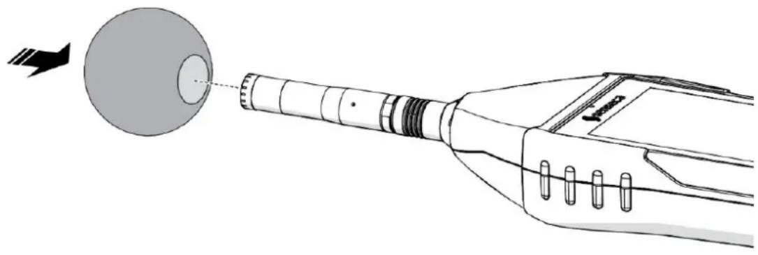
When making outdoor measurements in windy weather or when making measurements on air conditioning equipment, wind noise or air movement against the microphone can generate measurement errors. Such effects can be reduced by using a wind protection bonnet.
To avoid possible measurement errors, use the windscreen on the microphone, especially when there is strong wind or substantial airflow generated by equipment.

Info
Since the wind shield can protect the microphone from accidental shocks, it is recommended to use it even during indoor measurements.
natural_image
Diagram of a medical device with a spherical component and arrow indicating direction (no text or symbols)Fig. 10 - Assembly and disassembly of windscreen
5.4.3 Outdoor microphone unit
Disassembly of the Unit is necessary to perform, for example, calibration (partial disassembly only) or cleaning.

Info
- To pull out the top of the unit and perform calibration, follow steps 2 and 3.
• See the outdoor microphone unit manual for more information.
To completely disassemble the unit, you need to have a 2 mm hexagonal Allen wrench.
1 Unscrew the unit from the holder 1/2W or 1/4W, if any.
2 Using the Allen wrench, loosen the grub screw securing the top (A) of the protection.
3 Disconnect the upper part (A) of the guard from the lower part (B) by pulling it off the sensor (D); be careful not to damage the sensor.
4 To completely remove the sensor (D), disconnect it, via push-pull connector, from the extension cable (E) and pull the cable out by passing the connector through the hole (F).
To perform the assembly, proceed in the reverse way.
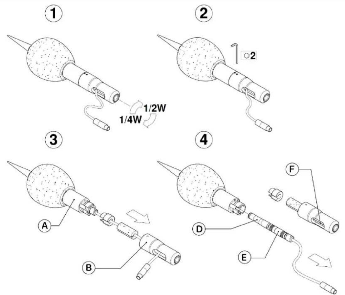
Fig. 11 - Disassembly of outdoor microphone unit
5.4.4 Connect the outdoor microphone unit to the sound level meter
After placing the outdoor microphone unit at the measurement site, it can be connected to the sound level meter.
1 Remove the microphone from the sound level meter, see section "5.4.1 Microphone and preamplifier" on page 32".
2 Insert the connector of the outdoor microphone unit into the sound level meter until you hear a small click, pay attention to the orientation of the red pin.
3 If necessary, use the extension cable provided.
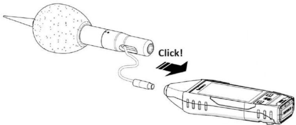
Fig. 12 - Outdoor microphone unit connection
5.4.5 Mounting on a tripod
To minimize operator influence on measurements, or in the case of measurements taken over long periods, the instrument can be mounted on a standard camera tripod using the 1/4" threaded hole on the back of the instrument, see "Fig. 1 - Hardware overview" on page 15.
5.5 Battery power supply
5.5.1 Battery power use
The instrument is supplied with the battery, already inserted in the battery compartment and with the connector disconnected. Please refer to the "5.5.3 Battery insertion and replacement" on page 37 to make the correct connector connection.
The current battery voltage is displayed in the status bar, where there is a status icon with a battery symbol. Battery discharge is displayed as a progressive emptying of the symbol.
- When the remaining energy is less than about 15%, the battery status icon is empty (no notch).
- A protection system prevents the instrument from making measurements with insufficient charge levels and, if it is in measurement, performs the measurement stop automatically. If the battery level drops further to the minimum level necessary to ensure functionality, the instrument automatically shuts down.
- When the battery voltage drops below 3.1 V, the sound level meter is unable to take measurements. However, it is still possible to access the data in memory and perform data downloading. Stored data and configuration and calibration parameters are retained even when the power supply fails.
Battery charge indicator
The battery icon, found in the status bar, displays the charging status of the battery. When the instrument is charging or external power is being used, the background of the icon is orange.
| Icon | Description | Icon | Description |
 | 85% ÷ 100% |  | 15% ÷ 35% |
 | 60% ÷ 85% |  | 0% ÷ 15% |
 | 35% ÷ 60% |  | Battery charging |
5.5.2 Charging the battery

Notice!
Use only a USB-C type cable paired with a standard cell phone power supply with the features listed below and suitable for mains power supply.
| Characteristics of the battery (supplied) | |
| Type | Rechargeable battery packLi-Ion polymer |
| Protection | PCM circuit for battery cell protection, temperature protection |
| Capacity | 9000 mA (3.7 V) |
| Operating time | >24 h |
| Charge time | 8-12 h depending on the charger used |
| Operating temperature | Charging 0...+45 °C, discharging -20...+60 °C |
| Battery life cycles | >500 complete discharge and recharge cycles with 80% initial capacity remaining |
| Power supply (not supplied) | |
| Output | 5 Vdc / 2.1 Ah / 10.5 W |
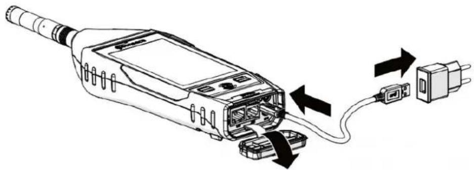
When the instrument is charging, the battery charge indicator has the orange-colored icon background. If connected to PC via USB, the charging current is limited to max 500 mA. If connected to battery charger, with instrument on and low power mode, charging current exceeds 1 Ah recharging batteries in less time. Successful charging is indicated by LED in the center button.
natural_image
Diagram of a handheld device with connectors and wiring, showing internal components and connection arrows (no text or symbols)Fig. 13 - Battery Charging
1 Connect the USB-C cable to the power supply and USB-C connector on the instrument.
2 Plug the power supply into a compatible electrical outlet.
3 When 100% charge is reached, remove the power supply and USB-C cable from the instrument.

Warning!
Do not leave the instrument on charge for longer than necessary, as soon as 100% charge is reached remove the power supply, this is to avoid overheating the battery and compromising battery life.
5.5.3 Battery insertion and replacement

Warning!
Before proceeding with battery insertion and/or replacement, make sure the instrument surface is dry and the instrument is turned off.
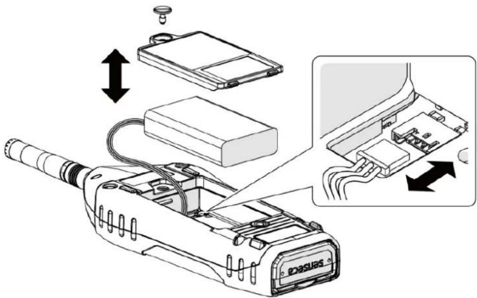
Fig. 14 - Battery insertion and replacement
1 Open the battery compartment at the back of the instrument by unscrewing the battery compartment screw.
Battery replacement
2 Remove the battery from the battery compartment.
3 3 Unplug the battery connector.
Inserting the battery
4 Connect the battery connector, the instrument will turn on automatically.
5 Insert the battery into the battery compartment.

Notice!
Make sure that the battery and its cables are fully inserted inside the compartment before closing the cover to avoid possible damage to them.
6 Replace the cover on the battery compartment.
7 Tighten the screw on the battery compartment.

Warning!
- In case of replacement use only original batteries to be ordered from Senseca Italy Srl. Use of non-original batteries will void the warranty.
- If you have any doubts regarding the type of battery to be used or its purchase, please contact your local distributor for further information.
5.6 External power supply
The instrument can be used with the power cord connected to one of the following external power sources:
- computer
- power-bank
• with power supply to the mains.
Using power supply via USB port
When the instrument is connected to the external power supply, it can operate properly with or without batteries installed.

Notice!
If you use XPT800 without batteries and the power supply is interrupted, you may lose data.

Warning!
In case the instrument is externally powered or is charging, do not remove the power cord before turning off the instrument. Removing the power cord with the instrument still on could result in the loss of unsaved data.

Info
The instrument can also be powered with the optional RJ12 connector (12-24 V/1 A), OH3B hardware option.
6 Switching on and off
6.1 Switching on
| 1 Press the ON key briefly:• the white LEDs of the LEFT/RIGHT buttons light up• the green LED of the ON button blinks | 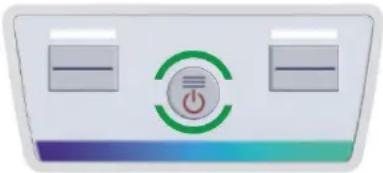 |
| • the screen turns on• the splash screen is briefly displayed• the main screen appears (ICON MENU)Note: If Auto-Load setting (10.4.3) is active, the SLM measurement screen appears directly | 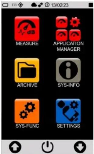 |
6.2 Display auto-off function
The function, if activated, turns off the display after a predetermined time. Refer to chapter "7.4.2 Setting the display auto power off" on page 44 to enable, disable or set this function.
With Timer display function active (icon present in the drop-down menu):
- successively access the pages SETTINGS > INTERFACES > DISPLAY and set a time between 1' and 1h;
- if the instrument is not used, the display will turn off after the set time;
- press any key or the display to exit the stand-by mode.
With display timer function NOT active (icon present in the drop-down menu):
- the display never turns off even if the instrument is not used for a long time.

Notice!
Using the instrument with stand-by function NOT active significantly reduces battery life, is highly recommended to use this function.
6.3 Switching off
| 1 Access the ICON MENU (see “Fig. 5 – Home page” on page 20) to display the menu control bar. |  |
| 2 Press the ON/OFF icon on the control bar for 3 seconds to access the OFF panel.3 Press the desired icon:Upper icon to switch off the instrumentCentral icon to cancel the operation and close the OFF panelLower icon to restart the instrument. | 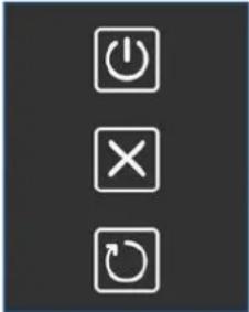 |

Warning!
In case the instrument is externally powered or is charging, do not remove the power cord before turning off the instrument. Removing the power cord with the instrument still on could result in the loss of unsaved data.
7 Settings and Adjustments
7.1 Set current date and time

Info
If the instrument is connected to the NTP server, you do not need to set the date and time. If you want to manually set the time and ignore any synchronization, you need to change the NTP server connection setting, see the chapter "7.2 Using NTP server to synchronize date and time" on page 42.

Notice!
Stop the measurement before setting the date and time, otherwise the new setting will take effect only at the next recording stop.
| 1 In the ICON MENU, press the SETTINGS icon to access the system and measurement configuration menus.1 Successively access the pages INSTRUMENT, SYSTEM and Date & time.2 Set the date, time and possible daylight-saving time correction3 Press √to confirm, press to×ancel the operation. | 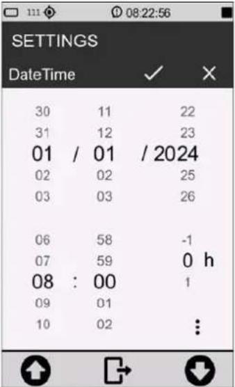 |
| 4 Press on the three dots to access the panel for selecting UTC and date format:DMY = day/month/yearMDY = month/day/year5 Press √to confirm, press to×ancel the operation. | 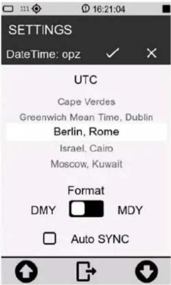 |
7.2 Using NTP server to synchronize date and time
XPT800 communicates with NTP servers to synchronize the internal clock with the most accurate time. This requires a valid Internet connection via Ethernet, GSM, or Wi-Fi; to make a connection to a network, see the section “12 Network and connections” on page 86.
For synchronization via NTP server to be possible, it is necessary that the parameter SETTINGS > INTERFACES > NETS > NTP service is set to ON.
| 1 Access the panel for setting the current date and time.2 Activate the item Auto SYNC.3 Press to confirm, press to cancel the operation. | 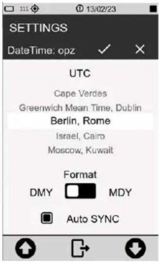 |

Notice!
The time required for updating the date and time by NTP server depends on the network access speed.
7.3 Setting the language
XPT800 has a built-in language translation function, and language preference can be set. For information on available languages, please refer to the sales department.
| 1 In the ICON MENU, press the SETTINGS icon to access the system and measurement configuration menus.2 Successively access the pages INSTRUMENT, SYSTEM and3 Language.4 Set the desired language.5 Press √to confirm, press to cancel the operation. | 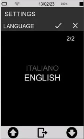 |

Notice!
Some languages may not be available with the firmware installed. Therefore, it is recommended to update the firmware periodically to have any new languages available.
7.4 Display adjustments
7.4.1 Adjusting the brightness
The brightness level is displayed in the status bar through the brightness adjustment slider. There is, in addition, an icon for activating automatic brightness adjustment.
To adjust the brightness of the display:
| 1 Access the status bar.2 Scroll the slider, left to decrease and right to increase the brightness.3 If you are working in an environment with significant lighting variations, it is recommended that you turn on automatic dimming using the appropriate icon | 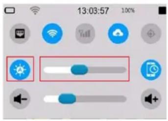 |
7.4.2 Setting the display auto power off
To set the display auto-off time.
| 1 In the ICON MENU, press the SETTINGS icon to access the system and measurement configuration menus.2 Successively access the pages INTERFACES, DISPLAY and Display timer.3 Select the desired auto-off time.4 Press √to confirm, press tocancel the operation. | 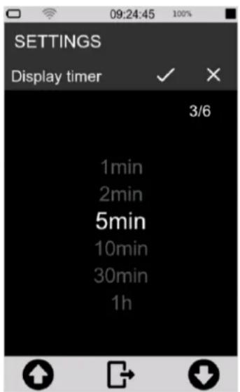 |
7.4.3 Selecting the display theme
| 1 In the ICON MENU, press the SETTINGS icon to access the system and measurement configuration menus.2 Successively access the pages INTERFACES, DISPLAY and Colors theme.3 Set the desired mode.4 Press √to confirm, press tocancel the operation.Changing the selected theme is visible only by returning to the ICON MENU. | 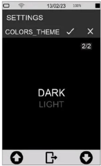 |
7.4.4 Turning the TOUCH display on and off
With touch display activated, it is possible to operate directly on the display; if deactivated, it is possible to operate the device only through the keyboard. To reactivate the touch display it is necessary to operate through the keyboard.
To turn the touch display on and off:
| 1 In the ICON MENU, press the SETTINGS icon to access the system and measurement configuration menus.2 Successively access the pages INTERFACES, DISPLAY and Display touch.3 Select the desired option (OFF to deactivate; ON to activate the touch display).4 Press √to confirm, press tocancel the operation. | 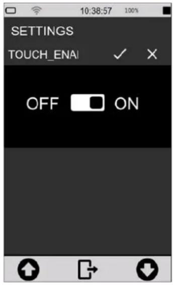 |
8 Viewing modes

Info
Display modes are available by accessing the MEASURE menu from the ICON MENU.
XPT800 calculates all broadband acoustic parameters in parallel with all available weighting filters. It allows parameter calculations with linear, exponential and moving averages. It also allows real-time and parallel calculations of broadband parameters with spectra in octave or third-octave bands. Functions for statistical analysis allow 7 percentile levels of broadband parameters and frequency spectra to be calculated in octave or third-octave bands; in addition, level distribution and cumulative functions are calculated.
The set of acoustic parameters selectable for display in the various graphical screens is completely independent of the set of parameters or groups of parameters selected for storage and datalogging. The parameters available for display are the full set while the parameters subject to storage are user-selectable through specific panels (see datalogging setup section).
The screens available for displaying data in numerical or graphical format are described below:
SLM (Sound Level Meter)
- 6 user-selectable parameters;
• Difference of levels (selectable);
• Bar graph of 3 broadband levels; - Display by colored icons of alarms triggered by exceeding settable thresholds;
- Display date and time of occurrence of integrated parameters (e.g., Max-Min).
TABLE
- All broadband parameters, weightings and time constant in parallel: Instantaneous, Average, Max-Min;
- 7 x Ln broadband percentiles, Ln moving, 7 x Ln for 1/1 or 1/3 octave frequency bands;
• Spectrum: Instantaneous, Min, Max, Average, Mov, Ln;
• Exceedances: current exceedances;
• No. of occurrences (SLM, Marker, Audio).
FREQUENCY SPECTRUM (Histogram)
- 1/1 or 1/3 octave histograms: up to 4 selectable with activatable/deactivatable traces. Numerical values @cursor position, Avg, Max, Min, Inst. Three broadband values histograms A, C, Z, U dependent on user setting;
- Selectable linear or weighted spectrum;
• Time constants: Lin, Fast or Slow; - Type: Inst, Mov, Avg, Max, Min, Rep-Avg, Rep-Max, Rep-Min, Evn-Avg, Evn-Max, Evn-Min.
TIME HISTORY
• 4 time traces of user-selectable parameters;
- Three broadband values histograms A, C, Z, U dependent on user setting;
- Display by colored icons of alarms triggered by exceeding settable thresholds;
- 5 horizontal bar indicators representing eventualities such as audio recordings or sound events;
- Positionable graphic cursor with time and level indication.
8.1 SLM mode
All displayed parameters can be freely chosen from those available. There are no constraints in the choice of frequency weightings. Measurement parameters are displayed with an abbreviated label, followed by the numerical value and the unit of measurement, possibly followed by the frequency weighting. The correspondence between the label and the actual parameter is provided in the appendix.
To display in SLM mode:
• from the home page select MEASURE menu;
- Use the icons <> to access the SLM screen.
Table 4 - SLM mode
| 1 | Measurement status bar: white when stopped; green when measurement is in progress; yellow when paused. |
| 2 | Pseudo-analog bar (dB): graphically shows 3 broadband levels |
| 3 | Primary parameters: with large font |
| 4 | Secondary parameters: with small font |
| 5 | Measurement control bar and context menu |
| 6 | Acquisition time: in hours: minutes: seconds |
In this mode it is possible to:
- Enable subtraction between two parameters: the obtained numerical value will be displayed in real time. Subtraction is possible only for the three primary parameters and not for the three secondary parameters.
- Selection of parameters to be displayed.
- Set Exceedances on/off.
• Perform a measurement with or without recording.
8.2 TABLE mode
Table mode provides numerical values of significant groups of preset parameters, the display of which cannot be changed, in the Instantaneous, Averages, Maximum-Minimum and SLM Exceedances screens. Spectrum screen provides numerical values in octave bands or third of octave of acoustic parameter groups selectable by touch from % (7 user-parameterizable percentile levels), Inst (instantaneous or moving-average spectra), GLB (integrated max, min, equivalent, moving spectra), REP (max, min, equivalent, moving spectra, calculated at Report time intervals), EVN (max, min, equivalent, moving event spectra).
To access the TABLE mode:
1 from the home page select MEASURE menu;
2 Use the icons <> to access the TABLE screen;
3 Use the arrows on the navigation bar to display the desired items.
Table 5 - TABLE mode
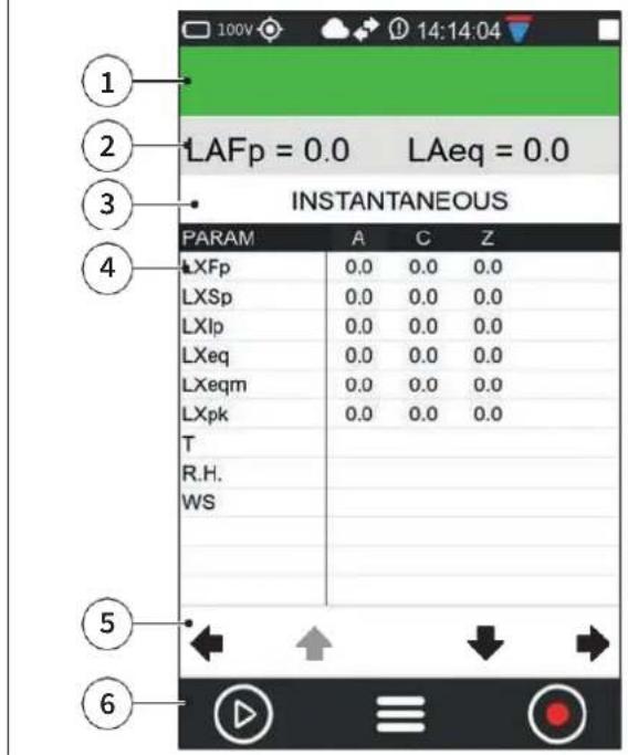 | 1 Measurement status bar: white when stopped; green when measurement is in progress; yellow when paused.2 Measurement instantaneous reference pa-rameters3 Page with instantaneous values4 Display of measured values5 Item navigation bar6 Measurement control bar and context menu |
In this mode the following items can be displayed.
INSTANTANEOUS
Shows instantaneous total values (broadband).
AVERAGES
Shows time-integrated measurement values of significant broadband parameter groups.
PERCENTILE AVERAGES
Shows the integrated values of the 7 percentile levels (values of the 7 percentiles that can be set in the menu SETTINGS > SOUND MEASURE > STATISTICS).
The four columns display respectively:
• LN broadband values integrated with linear average;
- LN broadband values integrated with moving average (the number in seconds indicates the duration of the integration moving window);
• LN values referring to # 1 frequency band (selectable);
• LN values referring to # 2 frequency band (selectable);
MAXIMUMS - MINIMUMS
Shows maximum and minimum integrated values of significant broadband parameter groups.
SPECTRUM
Shows instantaneous, minimum, maximum and average values in thirds of an octave or octave (depending on instrument settings) or frequency band values of other selectable parameters (LN percentile levels, events, ratios).
The parameter displayed on the column is user selectable.
SLM EXCEEDANSES
Shows the following exceedances:
• parameter exceeded;
- input/output thresholds;
• exceedance status;
• exceedances count.
MARKERS
Provides a count of the number of sound events (divided by name) identified by automatic or manual marker that occurred during a measurement. A symbol representing a bell indicates whether the trigger condition of the marker or event is active or inactive.
In this mode it is possible to:
- Perform a measurement with or without recording.
- Display the values of all parameters in real time during measurement/recording.
- For some parameters, the desired display can be set (SPECTRUM).
8.3 Octave and Third Octave display (histogram)
The frequencies and amplitudes of the sound signal analyzed through IEC61260-compliant constant percentage band digital filters are displayed in real time through a bar graph called a histogram. The graph allows superimposition and activation or deactivation of 4 different color curves related to user-selectable parameters and calculation modes even during measurement.
To access the HISTOGRAM mode (ISTOG.M):
1 from the home page select MEASURE menu;
2 Use the icons <> to access the ISTOG.M screen;
3 Use the icons in the display.
Table 6 - HISTOGRAM mode
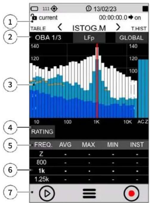 | 1 Measurement status bar:white when stopped;green when measurement is in progress;yellow when paused.2 Viewing options:the resolution (octaves or third octave) is displayed on the left.in the center the spectrum calculation parameter is selectable (LFp - LFeq - LFeqm)on the right is selectable the type of analysis for the spectrum between (Global - Report - Event)3 1/3 or 1/1 octave spectra (depending on the settings):White (black with LIGHT theme): maximumBlue: minimumLight blue: instantOrange: medium (dependent on parameter setting)4 RATING: allows, if enabled by menu (SET-TINGS > SOUND MEASURE > SPECTRA: Noise rating mode: RATING), the selection among the rating indices NC, RNC, NR, RC5 Show/hide spectrum, use the keys:AVGMAXMININST6 Numerical values of the spectrum:bold value line: selected cursor positionadjacent lines: previous and next frequency7 Measurement control bar and context menu | |
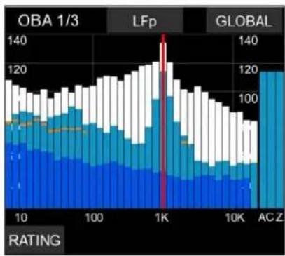 | Cursor activation: touch the touch screenLeft/right arrows: frequency selectionUp/down arrows: change full scaleZoom icons: change interval | |
In this mode it is possible to:
- Evaluate acoustic Ratings; tap RATING.
- Show or hide a spectrum; tap the spectrum label to display the desired plot. Label unselected is highlighted in black, for example:
• Avg OFF (Max, Min, Inst ON)
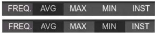
• Avg + Min OFF (Max, Inst ON)
- Navigate within the histogram; tap the histogram to display the cursor (red vertical line), use the display icons to move frequency and increase/decrease scale.

Info
For the complete list of values that the parameter "Spc_analysis_type" can take, see the section "19 Appendix B – Parameters" on page 104.
8.4 Time History display
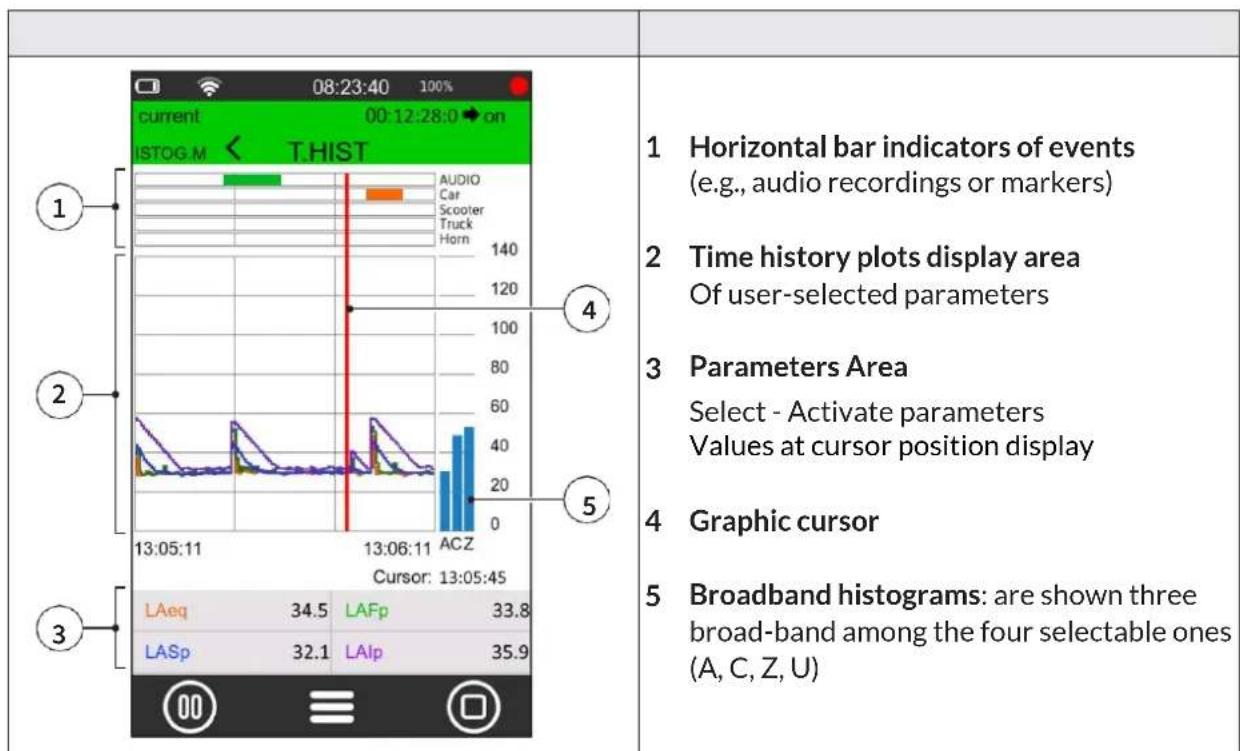
The Time History graph represents the time profile of several user-selectable acoustic parameters within a time window of defined width. The graph allows visual appreciation and numerical evaluation of the levels of sound events and their amplitude changes as a function of time. In parallel, it allows visual evaluation of the occurrence of sound events automatically detected by the sound level meter or manually highlighted by the operator during measurement for later analysis using post processing software NS-ENS.

Info
The selection of parameters to be associated with the 4 curves available for the time history graph, can be made through selection wheels. Tap on the parameter to display selection wheels
9 Getting started: Main Functions
The most frequently used functions are described below; for a complete discussion of the instrument operation and settings, see the section “10 Advanced functions” on page 66.
9.1 Calibration
Sound level meter calibration (adjustment) should be carried out periodically, normally before and after each measurement session, in order to ensure the validity of the measurements made by the sound level meter, as the sensitivity of the microphone and the response of the electronic circuits may vary slightly over time or may be affected by environmental conditions such as temperature, atmospheric pressure and humidity.
Acoustic calibration also includes internal electrical calibration. Electrical calibration enables the alignment of electrical parameters in the measurement chain

Info
- More information on calibration settings can be found in the chapter "10.1 Setting the calibration parameters" on page 66".
- Before starting the calibration procedure, carefully read the calibrator manual provided with the calibrator.

Notice!
- It is recommended to use the model HD2020 calibrator, supplied upon request
- Another class 1 calibrator conforming to IEC60942 and with 1/2" cavity can be used, after verifying compatibility and technical specifications.
- When using class 1 calibrators alternative to the HD2020 model, the nominal emission level stated in the calibration certificate must be verified, and the "Cal_Level" parameter in use in the menu related to the calibration setup must be adjusted. If stated by the manufacturer, corrections per load volume should be considered.
Before performing an acoustic calibration:
- make sure that the environment in which you are operating is suitable: no sudden noise, no vibration are present on the supporting surface, thermal stability of the instrument;
- make sure that the microphone and especially the microphone diaphragm are clean; in case a check of the condition of the microphone capsule is to be performed, refer to “14.2 Microphone cleaning (microphone diaphragm)” on page 94;
- in case of accessories installed on the instrument, such as a windshield if any, or if you want to customize the calibration settings, refer to section "10.1.1 Setup" on page 66;
- make sure that there is no measurement in progress; if it is, it must be stopped before starting calibration.
To perform a calibration:
1 Turn off the sound calibrator.
2 Carefully insert the microphone all the way into the cavity of the calibrator.
3 Turn on the XPT800 sound level meter.
4 Follow any specific recommendations in the calibrator manual in this regard.
| 5 In the ICON MENU, press the SYS-FUNC icon to access the system app menus.6 Access the CALIBRATION, PROCEDURE pages in succession.7 Set in the "Expected" field, if not yet set in the calibration setup (CALIBRATION > SETUP > Level), the nominal value stated by the manufacturer or taken from calibration certificate, of calibrator output (e.g., 94.00) at 1KHz frequency.8 Press "Play" to start the reading.9 If the level is enough stable, press "CAL" to start the adjustment procedure.10 The "CAL" button remains inactive until the calibration procedure is finished, so calibration corrections are not allowed. | 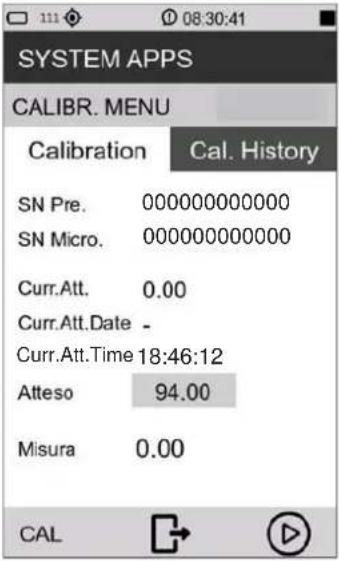 |
11 When done, turn off the sound calibrator, slide the microphone out of the cavity.
When the calibration is completed, the date, time and correction are updated. Access to the Calibration history panel is allowed only after the calibration is completed.
9.2 Setting the duration of a measurement

Notice!
If the measurement duration is not set, the measurement will not be interrupted unless manually or when the memory or battery runs out.
| 1 In the ICON MENU, press the SETTINGS icon to access the system and measurement configuration menus.2 Access the SOUND MEASURE, SETUP and Measure Timer pages in succession.3 Select the measurement duration.4 Press √ to confirm, press X to cancel operation. | 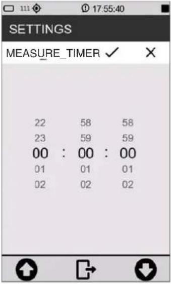 |
9.3 Select acoustic parameters to be displayed
The XPT800 sound level meter is capable of simultaneously calculating a very large set of broadband, frequency-band acoustic parameters with different spectral weightings in parallel. Thanks to this feature, it is possible for the user to change at any time, and even with measurement in progress, the parameters displayed in the available screens; thus, the possibilities for investigation of the sound phenomenon in progress will be virtually unlimited

Info
Editing the displayed parameters is also available from the context menu by selecting EDIT VIEW.
| 1 In the ICON MENU, press the MEASURE icon to enter the measurement panel.2 Touch the SLM parameter to be set (example LAeq). | 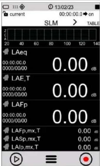 |
| 3 Press on the parameter name (e.g. LAeq) and select the new parameter and available options:First column: here all available parameters classes appear (example LXeq). See. “19.1.3 Classes of measurement parameters available for visualisation” on page 106Second column: here you can choose the available options (Weighting or frequency band).Third column: here you can choose the available options (Integration mode).For a complete description of the available parameters and options, see the section “19 Appendix B - Parameters” on page104. | 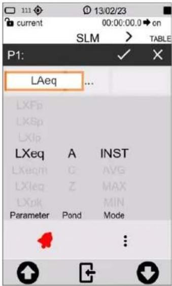 |

Info
It is also possible to:
- perform subtraction between two parameters, see chapter "9.5 Subtraction of two acoustic parameters" on page 58.
- set alarms and exceedances, see chapter "9.7 Set alarms on exceedances" on page 60.
9.4 Set acoustic parameters to be stored
The XPT800 sound level meter allows parallel storage of a very large set of acoustic parameters with sampling down to 10ms. Through the Time History, Report, Events, Globals storage groups, the user has logging tools that allow recording of sound phenomena both with high temporal resolution and with integrated sampling over medium or long times thus being able to quantify sound emissions on an hourly or daily basis, for example, or with hourly moving average integrations. In addition, storage of time histories and calculated acoustic parameter values of occasional events is also possible independently of continuous storage of levels, saving the user, if necessary, from storing data not of interest. The Time History, Report, Events, and Globals storage groups can be used simultaneously, providing the acoustician with a versatile logging tool that can be adapted to any need.

Info
All modified settings remain stored in the "current" and reloaded at power-up. The current setup, if modified, will be followed by an asterisk to indicate to the user that an unsaved change has occurred. If the user wishes, he/she can store the complete set of settings in a setup file by accessing APPLICATION MANAGER which is the application from which to manage the storage of the customized settings, see chapter "10.4 Custom measurement setups" on page 71.
MEASURE > EDIT APP > LOG >
- SETUP: setting of general log parameters such as sampling step, moving window, activation/deactivation of storage for specific analysis, time synchronization mode of storage.
- TIME HISTORY: activation/deactivation of storage of Instantaneous, Maximum, Minimum, Integrated and Auxiliary acoustic parameters, in Time History group.
- REPORTS: activation/deactivation of parameter storage and report interval, in Report group.
- EVENTS: activation/deactivation of storage of stored parameters, in Event group.
- GLOBALS: activation/deactivation of parameter storage in Globals group. Setting the calculation mode CONT or DAILY.
- AUDIO: activation/deactivation of audio recording in Continuous or Event mode. Setting of sampling and resolution characteristics, compression and maximum duration of audio recording.
| 1 In the ICON MENU, press the MEASURE icon to access the measurement panel. | 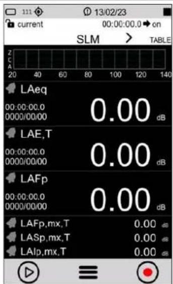 |
| 2 Tap on the context menu and select EDIT APP. | 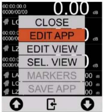 |
| 3 Select LOG. | 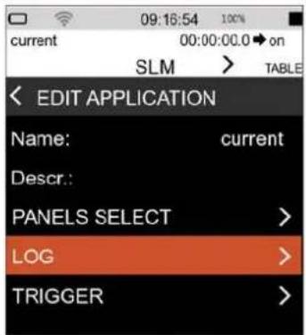 |
| 4 Select the required datalogging group (example TIME HISTORY). | 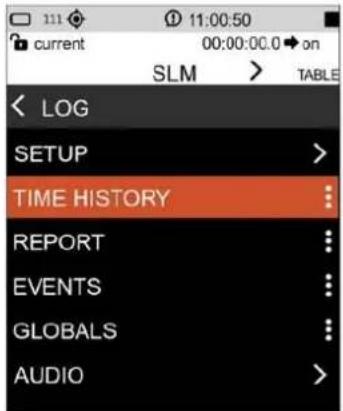 |
| 5 Tap the check box to select one or more parameters to be recorded. | 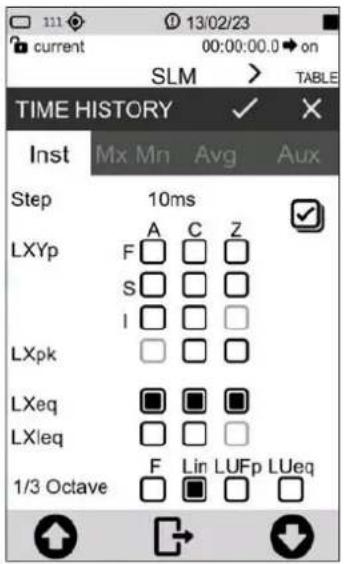 |
 InfoThe Time History logging interval setting can be found on the EDIT APP > LOG > SETUP page. InfoThe Time History logging interval setting can be found on the EDIT APP > LOG > SETUP page. |
 InfoThe Reports logging interval setting can be found on the EDIT APP > LOG > REPORTS panel InfoThe Reports logging interval setting can be found on the EDIT APP > LOG > REPORTS panel | 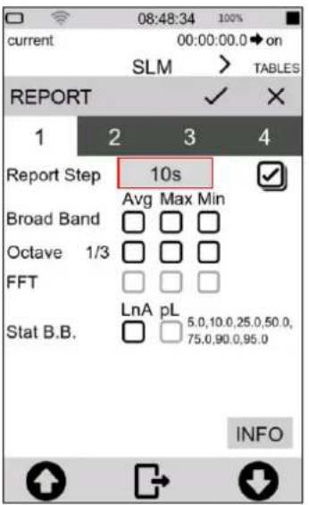 |
9.5 Subtraction of two acoustic parameters
For specific measurement applications, it may be necessary to directly detect the level difference between two acoustic parameters whose correlation is significant for the evaluation of a sound event. The XPT800 allows direct display calculation of the difference between any two freely selectable acoustic parameters such as, for example, LAleq - LAeq to evaluate the impulsive character of a sound source, LCeq - LAeq in noise exposure assessment or PPE evaluation using the HML method
| 1 In the ICON MENU, press the MEASURE icon to access the measurement panel.2 Select the parameter to which you want to apply the subtraction (example LASp), | 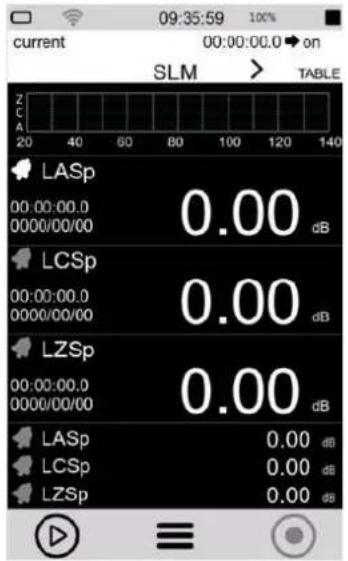 |
| Infoit is only possible for the three primary parameters (big numbers) and not for the three secondary parameters (small numbers) | |
| 3 Tap on the center field to activate the subtraction function, the " - " subtraction sign appears. | 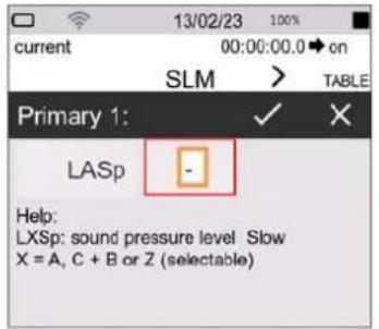 |
| 4 Tap the right field to select the second parameter.5 Press √ to confirm, press X to cancel operation. | 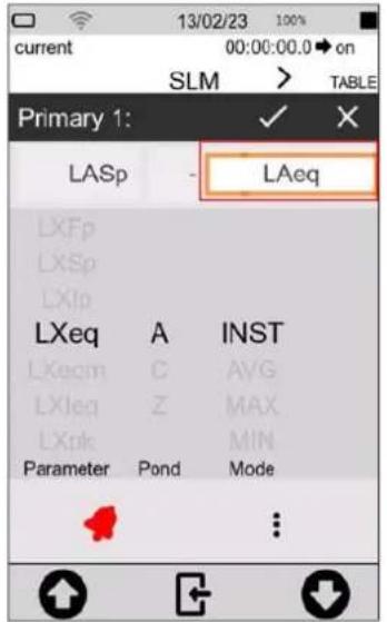 |
| InfoTo modify the displayed parameters, see “9.3 Select acoustic parameters to be displayed” on page 54. |
9.6 Load a custom configuration
To load an existing configuration, follow the steps below.:
| 1 In the ICON MENU, tap the APPLICATION MANAGER icon to access to the custom measurement app selection and management panel.2 Select and load the configuration by tapping on it directly Or:3 tap at least 2 seconds and use the context menu controls. Select LOAD | 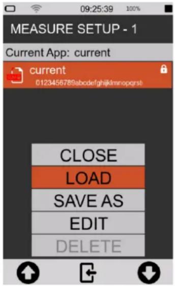 |
4 The configuration is immediately activated and ready for use. InfoThe name of the loaded configuration is shown on the upper left part of the screen InfoThe name of the loaded configuration is shown on the upper left part of the screen | 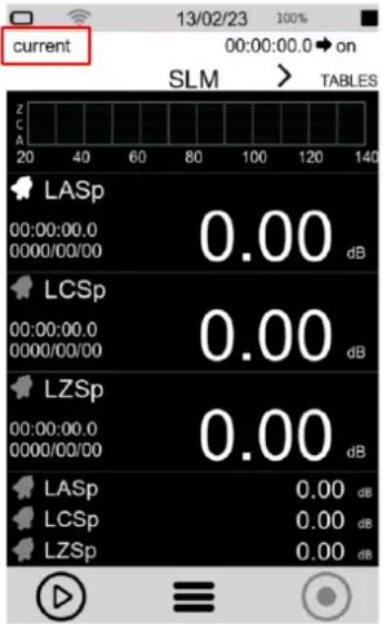 |

Info
For a full explanation of custom configurations, see the chapter "10.4 Custom measurement setups" on page 71.
9.7 Set alarms on exceedances
The function allows specific actions to be automatically triggered when specific conditions are reached such as exceeding a certain noise level detected by the instrument for a certain acoustic descriptor. Reaching the triggering conditions can, for example, automatically generate recording of the audio signal when the noise level exceeds a certain value and stopping recording when the level returns below the set value.
| 1 In the ICON MENU, tap on the MEASURE icon to access the measurement panel.2 Tap on the SLM parameter to be set. | 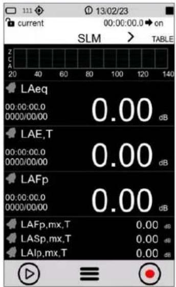 |
| 3 Select the parameter used for exceedance/alarm, to change the parameter to be set see chapter “9.3 Select acoustic parameters to be displayed” on page 54.4 Tap the bell to activate (the bell turns red when active).5 Tap the three dots to set the threshold. | 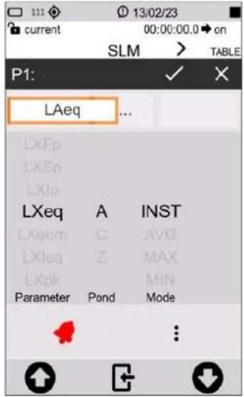 |
| 6 Enter the threshold values, mode and duration (see also “20.1 Exceedances settings” on page 112). Changes are directly activated by going back. | 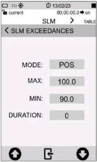 |
| 7 The black bell indicates that the alarm is ready and waiting for the threshold to be exceeded. | 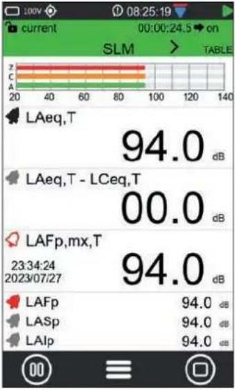 |
| 8 Description example of exceedance/alarm status. | 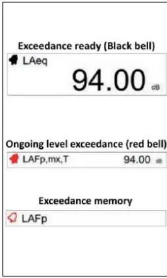 |
9.8 Starting and stopping a measurement
The XPT800 sound level meter allows measurements of sound levels even without data storage. The two measurement modes, with and without datalogging, use common acoustic descriptors calculation functions. Through the graphical interface, the choice of measurement mode is made by means of commands available on the measurement control bar. In the status bar, a specific icon indicates the active measurement mode.

Notice!
- With this mode, there is no recording of measurements. Values will not be stored, only displayed.
- When measuring outdoors with high humidity and using the outdoor microphone unit, it recommended to use the preamplifier heater, see "10.8 Activating the preamplifier heater" on page 78.
| 1 In the ICON MENU, press the MEASURE icon to access the measurement panel or select a pre-configured configuration, see chapter “9.6 Load a custom configuration” on page 59.2 Tap the left icon of the control bar to perform the measurement without datalogging. | 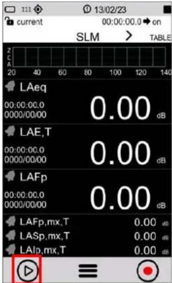 |
| 3 Measurement in progress (see the green arrow measurement icon in the upper right corner).4 Tap the left icon to PAUSE, press again to resume measurement.5 Tap the right icon to STOP measurement, no data will be stored. | 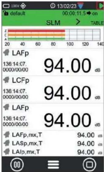 |
9.9 Starting and stopping a measurement with datalogging
The XPT800 sound level meter enables measurements of sound levels with data storage. The measurement mode uses common calculation functions. Through the graphical interface, the choice of measurement and storage mode is made through commands available on the measurement control bar. In the status bar, a specific icon indicates the active measurement mode. The measurement mode with logging assumes that the user has set the desired measurement parameters in the LOG menu. The LAeq parameter is always stored even if the user has not selected any parameters.

Notice!
- With this function, the measurement is recorded, the data will be stored.
- When measuring outdoors with high humidity and using the outdoor microphone unit, it recommended to use the preamplifier heater, see "10.8 Activating the preamplifier heater" on page 78.
| 1 In the ICON MENU, press the MEASURE icon to access the measurement panel or select a pre-configured setup, see chapter “9.6 Load a custom configuration” on page 59.2 Tap the right icon of the control bar to perform the measurement with datalogging. | 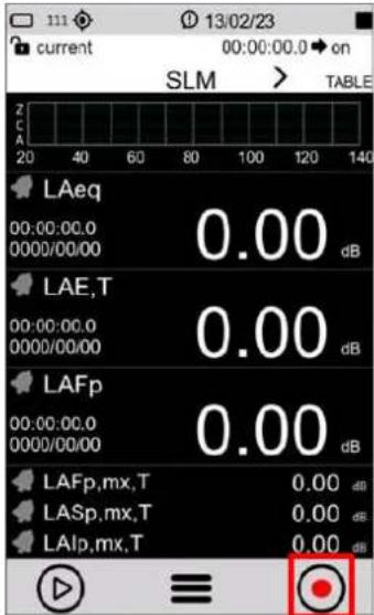 |
| 3 Measurement in progress (see the red circle measurement icon in the upper right corner).4 Tap the right icon to STOP measurement, data will be automatically stored. |  |
9.10 Recording an audio manually
The Audio function allows the sound signal from the sound level meter transduction chain to be recorded at the same time as the measurement parameters. The signal thus recorded can be used for replay by means of an audio playback program or through the NS-ENS software module. The instrument allows recording to be triggered either manually or automatically through user-settable trigger functions. Manual and automatic modes can also be used in conjunction during a measurement.

Info
To setup the instrument correctly, please refer to the chapter "10.3 Setting audio recording parameters" on page 69.

Notice!
With this function, audio recording and measurement recording are carried out simultaneously.
| 1 Start a measurement with recording, see chapter “9.9 Starting and stopping a measurement with datalogging” on page 63.2 The measurement with recording is running (see the red circle recording icon in the upper right corner).3 Tap the "audio" icon on the left to start an audio recording. |  |
| 4 The audio recording icon turns green when audio recording is active. The icon in the upper right corner indicates the status o audio recording.5 Tap the "audio" icon again to stop audio recording.6 Tap the right icon to stop recording the measurement. |  |
9.11 Manually add markers to the measurement
The MARKERS function allows specific time portions of the measurement to be highlighted with markers. The markers can be associated with specific user-customizable names such as Car, Truck, Aircraft, etc. The time portions thus highlighted are stored in the data file synchronous with the measurements and can be viewed using the NS-ENS analysis software with which its levels can be evaluated.

Notice!
This function is only available during a measurement with recording.
| 1 Start a measurement with recording, see chapter “9.9 Starting and stopping a measurement with datalogging” on page 63.2 The measurement with recording is running (see the red circle recording icon in the upper right corner).3 Tap the context menu and select MARKERS. |  |
| 4 Tap the left/right arrows to select the desired marker name.5 Tap the marker name to apply the marker |  |
| 6 Active marker, Tap the marker name again to stop. |  |
| 7 Select BACK with the arrows and tap to exit the markers |  |

Info
To add and customize markers refer to the chapter "10.5 Customizing markers" on page 73.
10 Advanced functions
10.1 Setting the calibration parameters
The XPT800 sound level meter, with the standard transduction chain consisting of the MP800 preamplifier and model MP800 class 1 free-field microphone, is adjusted at the factory and delivered calibrated. Adjustment with a class 1 sound calibrator should be carried out periodically, normally before and after each measurement session, to ensure the validity of the measurements made by the sound level meter, as the sensitivity of the microphone and the response of the electronic circuits may vary slightly over time or may be affected by environmental conditions such as temperature, atmospheric pressure and humidity. In addition, XPT800 has an internal compensation function for environmental conditions corrections.
10.1.1 Setup
The instrument allows settings of the following parameters:
• Acoustic Field corrections;
• Windscreen and Outdoor microphone protection corrections (Shield correction);
- Emission level of sound calibrator used (Level);
- Calibration mode, manual or automatic.
To setup the calibration parameters of the instrument:
| 1 In the ICON MENU, press the SYS-FUNC icon to access the system and measure configuration menus.2 Access the CALIBRATION and SETUP pages in succession.3 Set the desired parameters. | SYSTEM APPS<SETUPELECTRIC cal. corr. 0.00dBElectric cal. level 91.0dB :Calibration mode MAN :El. calibration OFF :Electric cal. timer: 1h :Microphone input MIC :Environmental corr. ON :Shield correction WS90 : |
Acoustic field
With the supplied MC800 microphone, which has a frequency response optimized for "Free Field" (FF), if the parameter is set to "Free Field" (FF), correction is applied accordingly. Correction by random incidence can be enabled by setting the parameter to "Random Incidence" (RI). This setting is necessary for surveying in accordance with ANSI standards. For example, in case you choose a microphone with frequency response optimized for "diffuse field," the normal setting is "Random Incidence" (RI). You can enable correction for making free-field measurements by setting the parameter to "Free Field" (FF). This setting is necessary for measurements in accordance with IEC standards.
Correction applied for the use of WS90 or WSO windscreens (Shield correction)
Allows the sound level meter's frequency response to be corrected when either the windscreen WS90, supplied with the sound level meter, or the outdoor protection kit WSO is used. When this parameter is set to WS90, WSO the sound level meter's frequency response is corrected for the pres-
ence of the windscreen or outdoor protection respectively.
Calibrator emission level (Level)
This is the nominal emission value of the acoustic calibrator used for adjustment of readings; it is stated by the manufacturer or obtained from calibration certificate. The instrument must be set to the same level by setting precisely the Cal_level parameter; the possible range is 90.00 ÷ 130.00 dB.
Correction applied after calibration (Correction)
The current correction level is shown after a successful calibration procedure. The correction level expressed in dB, indicates the level difference applied by the calibration algorithm from the factory calibration.
Calibration mode
The following options are available:
- Manual (MAN);
• Automatic (AUTO).
Automatic: when Calibration Mode is set to AUTO, the instrument uses detectors to automatically detect the presence of a calibration tone in the signal coming from the microphone. When the calibration tone is detected, a pop-up prompts the user to perform calibration.

Info
For a complete description of the available parameters and options, see the section "19 Appendix B – Parameters" on page 104.
10.1.2 Calibrations History
The XPT800 sound level meter, after each adjustment, stores in the "Calibration History" page the results of the calibration procedures performed with the date, time, and correction factor in dB compared to the factory calibration stored in the device.
| 1 In the ICON MENU, press the SYS-FUNC icon to access the system app menus.2 Access the CALIBRATION and PROCEDURE pages in succession.3 Access the panel "Cal. History.". | 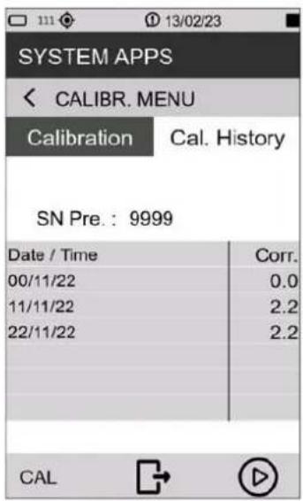 |
10.2 Setting triggers
The XPT800 sound level meter has an advanced user-configurable trigger feature. Based on the input parameter setting, the trigger automatically generates "actions" useful for identifying and measuring sound events or sending an analog signal on the I/O output (trigger out) for other types of uses such as triggering external devices.
Triggering can be set through parameters such as both broadband and frequency band sound level thresholds, duration, positive or negative polarity, and pre-trigger time. For details on triggering parameters refer to the section "19 Appendix B – Parameters" on page 104.
| 1 In the ICON MENU, press the MEASURE icon to access the measurement panel. | 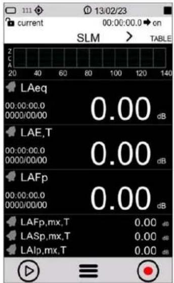 |
| 2 Tap on the context menu and select EDIT APP. | 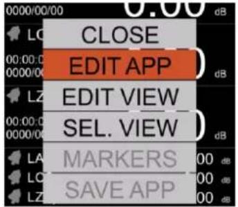 |
| 3 Tap TRIGGER and INPUT in succession to access the TRG Input page.4 In the SLM panel, tap the check box to activate the input parameters for trigger/event, among those to which surplus has been previously assigned, and the desired logic (AND/OR). Parameter in grey have no exceedance activated.5 Press √to confirm, press tocancel operation. | 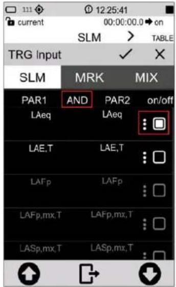 |
| i InfoAvailable parameters for triggering depend on the alarm/exceedances settings, see chapter “9.7 Set alarms on exceedances” on page 60. |
10.3 Setting audio recording parameters
It is possible to set the instrument to record an audio signal while logging acoustic values. You can, in addition, set parameters, such as the duration, bandwidth, and resolution of the audio recording.
| 1 In the ICON MENU, press the MEASURE icon to access the measurement panel.2 Tap on the context menu and successively select EDIT APP > LOG > AUDIO and the parameter to be set:Audio logging (Log_audio_mode);Audio resolution (Log_audio_res);Sampling rate (Log_audio_samp);Audio formatMaximum duration (Log_audio_duration).3 Set the desired parameters.4 Press √ to confirm, press X to cancel operation. | 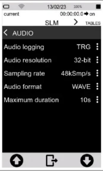 |
10.3.1 Audio recording mode
By acting on the "Log_audio_mode" parameter, audio logging can be set to:
- disabled (OFF): durante la registrazione dei dati non avviene nessuna registrazione audio;
- continuous audio recording (CONT): the audio signal is stored without interruption until the end of the measurement with datalogging.
- event-driven audio recording (TRG); audio recording, during a measurement with datalogging, is activated only when the set trigger condition is reached and is deactivated when the trigger condition is no longer satisfied.
Continuous audio recording
During "continuous" audio recording, the audio signal is stored without interruption until the end of the measurement.
Event-based audio recording
During "event-driven" audio recording, the audio signal is stored only when the set trigger condition is reached and is deactivated when the trigger condition is no longer met. It is possible, during the same measurement, to record another audio if the set trigger condition is met again.
To enable event-based audio recording, it is also necessary to set and activate the exceedances on the desired parameter as well, as described in the chapter “9.7 Set alarms on exceedances” on page 60.
| 1 In the ICON MENU, press the MEASURE icon to access the measurement panel.2 Tap on the context menu and select in succession EDIT APP > TRIGGER > INPUT.3 In the SLM panel, tap the check box to activate the input parameters for trigger/event, among those to which exceedance has been previously assigned, and the desired logic (AND/OR)4 Press √to confirm, press to cancel operation . | 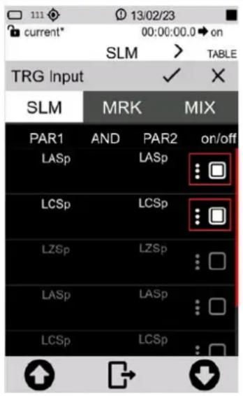 |
10.3.2 Audio recording resolution
It is possible to set the amplitude resolution of the audio signal. Higher resolution (e.g. 32 bits) corresponds to larger .wav files.
Parameter Audio resolution: you can select the resolution from the following values:
- 16 bit
- 24 bit
- 32 bit
10.3.3 Audio recording sampling frequency
The audio signal sampling frequency can be set. A higher sampling rate (e.g., 48 KSmp/s) corresponds to a higher bandwidth. The selection of the sampling frequency affects the size of the stored wave files; for example, a recording at 12KSmp/s, for the same duration, will have a lower memory occupancy than a recording at 48 KSmp/s; however, sounds over 5 KHz will not be audible in recordings made at 12 KSmp/s.
Sampling rate parameter: you can select the audio band from the following values corresponding to:
- 5k (12KSmp/s)
• 20kHz (48KSmp/s)
10.3.4 Setting a duration limit to audio recordings
Maximum duration parameter: you can select the maximum duration from the following values:
• INF (no duration set, audio recording stops when data logging is finished)
• 10s 1m; 2m; 5m; 10m; 30m; 1h (audio recording stops when the set time is reached)
10.4 Custom measurement setups
In the APPLICATION MANAGER section, the user is provided with a comprehensive manager of custom applications. The manager allows simple and fast operations such as selecting and loading setups or custom measurement applications for on-the-fly activation of the instrument with the desired settings for a specific measurement. The manager also allows the user to store one or more custom setups by assigning them a name and description, creating a database of setups that can be recalled as needed
For each setup, it is also possible to activate specific attributes for modification protection (Lock) or self-loading (Autoload).
10.4.1 "Current" Configuration
"Current" Is a configuration that is always available in the device and cannot be deleted (red icon

- Current is the in-use configuration. You can change the settings that will be retained even after the instrument is turned off. To save local changes, it is necessary to create a custom configuration with the "SAVE AS" command.

Notice!
"Current" configuration cannot be deleted.
10.4.2 Load, Edit, Save as, Delete functions
In the APPLICATION MANAGER section, it is possible to load an existing configuration, edit, save a new one, and delete configurations that are no longer used.
User-created configurations have the green icon, can be edited and deleted.

Info
To load a custom configuration, please refer to the "9.6 Load a custom configuration" on page 59.
| 1 In the ICON MENU, press the APPLICATION MANAGER icon to access to the custom measurement app selection and management panel.2 Select the configuration by tapping it for at least 2 seconds or by using the arrows and context menu commands.3 The following operations are possible:CLOSE = closes the context menuLOAD = loads the selected configurationSAVE AS = creates a new configuration from an existing oneEDIT: allows to activate attributes Lock and Autoload; consult section “10.4.3 “Lock” and “Auto-Load” ” on page 73DELETE = cancel selected configuration, “Current” cannot be deleted | 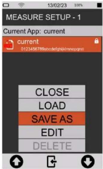 |
| To create a new configuration:4 After selecting SAVE AS fill in in the required fields.5 Press √to confirm, press tocancel operation .6 The new configuration (example “configuration_1”) appears in the list, to be used it must first be loaded with the LOAD function (context menu) or directly tapping on it | 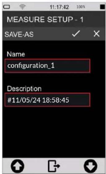 |
| To delete a configuration created by the user:7 simply tap on the configuration name for at least 2 seconds and press on DELETE in the context menu, you will be prompted to confirm, press OK. | 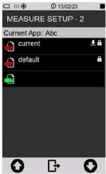 |
10.4.3 "Lock" and "Auto-Load" attributes
Each setup/application can be customized with Lock and Auto-Load attributes.
- LOCK: the application/setup is protected from overwriting
- AUTOLOAD: the application/setup with Auto-Load attribute activated (only one application at a time can have the attribute activated), is automatically loaded when the instrument is turned on and the related measurement screen is directly displayed
Lock and Auto-Load attributes can only be activated in APPLICATION MANAGER.
| 1 In the ICON MENU, press the APPLICATION MANAGER icon to access the custom configuration selection and management panel.2 Select the configuration by tapping it for at least 2 seconds or by using arrows and context menu controls.3 Tap EDIT and activate check box "Lock" or "Auto-Load" or both. | 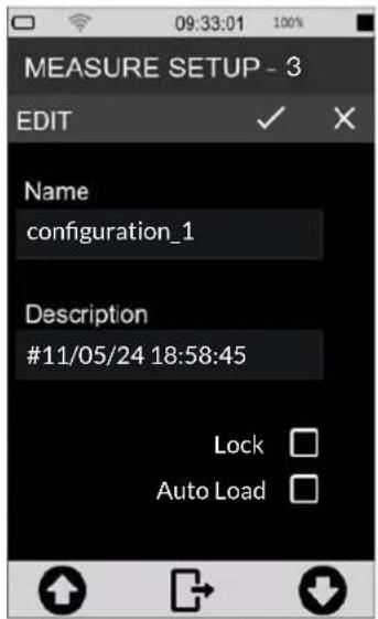 |
10.5 Customizing markers
It is possible to select markers to be available during a measurement to "mark" specific events, as well as to add new ones, change their names and settings. To use markers during a measurement, see the chapter "9.11 Manually add markers to the measurement" on page 65.
| 1 In the ICON MENU, press the MEASURE icon to access the measurement panel.2 Tap on the context menu and select in succession EDIT APP, TRIGGER, INPUT.3 In the MRK panel tap the check box to activate the markers to be made available during measurement.4 Tap the three dots to access the customization panel for each marker to change its name5 Press √ to confirm, press X to cancel operation. | 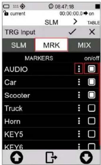 |
10.6 Continuous measurements datalogging
The XPT800 sound level meter allows the parallel storage of a set of acoustic parameters with sampling rates down to 10ms. Through the Time History, Report, Events, Globals storage groups, the user has tools at his disposal to record sound phenomena both with high temporal resolution and with integrated sampling over medium or long times, thus being able to quantify sound emissions on an hourly or daily basis, for example, or with hourly moving average integrations. In addition, the storage of time histories and calculated noise parameter values of events is also possible independently of the continuous storage of levels, saving the user, if necessary, from storing data not of interest. The Time History, Report, Events and Globals storage groups can be used simultaneously, providing the acoustician with a versatile and adaptable logging tool for every need.
10.6.1 Recording Configuration
1 In the ICON MENU, press the MEASURE icon to access the measurement panel.
2 Tap on the context menu and successively select EDIT APP, LOG, SETUP and the parameter to be set from the following:
- History interval
- Measure name (Log_name)
- max file size (Log_file_size)
- Log synchronization (Log_sync)
- Sync Files (Log_sync_type)
- Start of Reports (Report_sync)
- Sync. backlog (Sync_files)
3 Set the desired options.
4 Press to confirm, press to cancel operation
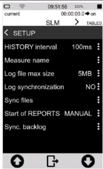

Info
You can change the same parameters from ICON MENU by tapping the SETTINGS icon and DATALOGGER > SETUP page.
History interval
Allows you to set the sampling step, i.e., the period between storing one sample and the next, of the acoustic parameter (or groups of acoustic parameters) selected.
Measure name (Log\_name)
A user-editable prefix e.g. MYNAME_DATE_TIME can be applied to the folder name automatically generated with each log, characterized by default by the date and time of the measurement.
Log file max size (Log\_file\_size)
Limits the size of files generated during continuous recording to a user-selectable value in MB (1, 2, 5, 10, 20, 50, 100MB). Files thus generated within the folder are named, for example, as history_0001.dodl, history_0002.dodl. An automatic queuing function present in the management software and in the NS-Storage portal allows the records divided as follows, to be merged into a single trace.
Log synchronization (Log\_sync)
Activates the automatic data synchronization mode on cloud. The function can be activated directly with the button in the drop-down menu. If log_sync is on, storage support cannot be accessed via USB
Sync files (Log\_sync\_type)
Allows selection of file types to be synchronized to cloud among: Reports, Events, Globals, Audio.
Start of Reports (Report\_sync)
If set to "CLOCK" it aligns the calculation time window of Report parameters with the nearest "round" time. For example, if Report_Step set to 1h and Report_sync set to clock, the integration time window will go from 9:00 to 10:00, 10:00 to 11:00, and so on. If Report_sync set to "MANUAL" and Report_step set to 1h, the integration window will go from the time of measurement start (e.g. 08:45:00) to the next hour (e.g. 09:45) and so on.
Sync backlog (Sync\_files)
View the list of files waiting for synchronization
10.6.2 Continuous datalogging of Time History group
Continuous recording of the "time history" group includes subgroups of Instantaneous (Inst), Maximum and Minimum (Mx Mn), Integrated (Avg) and Auxiliary (Aux) parameters.
For each subgroup it is possible to select by checkbox one or more parameters that are stored with user-defined step (menu SETUP > History interval), displayed at the top of the parameter selection panel.
When for the "Time history" group, the user selects at least one parameter, the log function of the instrument, stores in the memory at least one file of the type history.dodl. A folder identified by date and time, containing *.dodl files, is created with each measurement. The folder may contain other types of files with specific functions

Info
For more details on the acoustic parameters (Parameter Classes) that can be stored through the "time history" group, please refer to the section "19 Appendix B – Parameters" on page 104.
10.6.3 Continuous datalogging of Reports group
The continuous recording function of the "Reports" group allows the selection of one or more acoustic parameters with storage interval independent of the storage interval set for the "time history" group. The storage interval (Report step) can be set by the user directly from the parameter selection window via the drop-down menu in EDIT APP > LOG > REPORTS.
When for the "Reports" group, the user selects at least one parameter, the log function of the instrument, stores in the memory at least one file of the type reports.dodl. A folder identified by date and time, containing *.dodl files, is created with each measurement. The folder may contain other types of files with specific functions.

Info
For more details on the acoustic parameters that can be stored through the "Reports" grou please refer to the section "19 Appendix B – Parameters" on page 104.
10.6.4 Datalogging of Events group
The "Events" group includes parameters related to specific sound events, calculated, for example, following the activation of a trigger, for an integration time Te (individual event duration).
When for the "Events" group, the user selects at least one parameter, the log function of the instrument, stores at least one file of the type events.dodl. For each measurement, a folder identified by date and time is created, containing *.dodl files. The folder may contain other types of files with specific functions.

Info
For more details on the acoustic parameters that can be stored through the "Events" group, please refer to the section "19 Appendix B – Parameters" on page 104.
10.6.5 Recording Globals group
When for the "Globals" group, the user selects at least one parameter, the log function of the instrument, stores in memory at least one file of the type Globals.dodl. With each measurement, a folder identified by date and time is created, containing *.dodl files. The folder may contain other types of files with specific functions.
At the top of the Global parameter selection panel (EDIT APP > LOG > GLOBAL), you can select the calculation mode (Log_globals_mode) between CONT (Continuous) or DAILY (Daily). With CONT mode selected, the integration of global parameters continues after time 00:00 and ends when the measurement is stopped. With DAILY mode selected, the integration of global parameters ends at time 00:00 and resumes, after integration reset, with a new integration of data after time 00:00 and ends the next time 00:00 or upon STOP by the operator

Info
For more details on the acoustic parameters that can be stored through the "Global" group, please refer to the section "19 Appendix B – Parameters" on page 104.
10.7 PLAYBACK and GENERATOR
XPT800 has a built-in codec that allows, even while storing acoustic parameters, playback of signals through the audio output connector (∅ 3.5 mm jack socket). To play signals, select the desired play_channel. Playback is activated as soon as the measurement START button is pressed.
10.7.1 PLAYBACK management
SETTINGS > INTERFACES > PLAYBACK
Channel (Play_channel): allows you to select the playback channel between Generator, Trace (wav) or Measure (Meas)
- By selecting GEN "Generator," the instrument plays signals generated through the SETTINGS > INTERFACES > GENERATOR function.
- By selecting TRACE, the instrument plays wav files previously stored in the folder unit_name:\XPT800_My_serial_number\Traces*.wav.
- By selecting MEAS "Measure," the instrument plays the sound detected by the microphone directly-to the jack output.
Other available parameters:
- Repetition (Play_repetition) enables continuous playback of the selected track.
- Traces (Play_trace) allows selection from a list of the track to be played (the list is updated each time the instrument is restarted).
- Filter type (Hearing_channel), when Play_channel set to MEAS, allows selection of playback of unfiltered microphone signal (MIC), broadband filtered (WB), or third-octave band filtered (TOCT).
- WB filter (Hearing_pond), if Hearing_channel set to WB, allows you to select the frequency weighting applied to the signal between A, C, AUX.
- Th. Octave band (Play_toct_band), if Hearing_channel set to TOCT, allows you to select the 1/3 octave band applied to the playback of the microphone signal.
10.7.2 GENERATOR management
Through the generator function, acoustic signals can be created without the use of an external generator. The user can define signal properties by adjusting parameters such as frequency, duration and amplitude. The instrument automatically creates the signals as defined and stores them in wave format in the unit_name:\XPT800_My_serial_number\Generator\ folder. Once the signals have been created, they can also be played back during measurements
Available parameters:
- Frequency (Gen_frequency) lets you select the frequency of the signal.
- Amplitude (Gen_amplitude) allows you to select the amplitude of the generated signal.
- Duration (Gen_duration) allows you to set the duration of the signal (max duration 10s).
- Files (Gen_file) to select the signal to be played back to jack output.
10.8 Activating the preamplifier heater

Notice!
Activation of the heater increases energy consumption and reduces autonomy.
Humidity in the air, coming into contact with cold surfaces, can generate condensation. In particular, the metal components of the transduction chain consisting of the preamplifier and microphone capsule can be affected by condensation, which can cause disturbance with the measurement and, in severe cases, damage to the transduction chain.
The heater inside the preamplifier, in conjunction with the WSO outdoor microphone protection, reduces the risk of damage to the transduction chain and ensures that measurements are not affected by high levels of humidity on the microphone capsule membrane.
| 1 In the ICON MENU, press the SETTINGS icon to access the system and measurement configuration menus.2 Access pages SOUND MEASURE > SETUP and Preamplifier heater3 Select the desired option (OFF = heater off; ON= heater on).4 Tap √ to confirm, tap X to cancel | 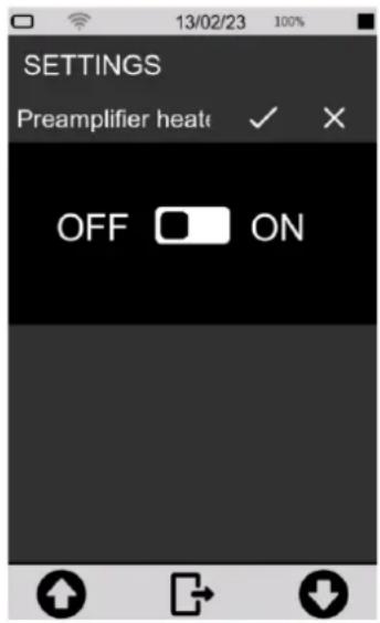 |
10.9 Monitor
The XPT800 sound level meter has a monitoring program to check some hardware functions.
The following parameters are checked:
- Battery voltage;
- Battery level;
- Temperature
- Pressure
- Charge voltage
- Preamplifier temperature
| 1 In the ICON MENU, press the SYS-INFO icon to access the system app menus.2 Access the MONITOR page. | 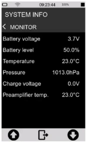 |
11 Managing measurement data files
Each time a measurement with logging is performed, a folder is created in the active storage device containing data files with the extension *.dodl and other file types.
The folder path is as follows:
Unit_name:\XPT800_My_serial_number\Measure\yyyyMMdd_hhmmss\
If the parameter SETTINGS > DATALOGGER> SETUP> Log_sequence = OFF, the instrument creates a folder with the start date and time of the new acquisition in the name. In this way, each measurement corresponds to a new folder.
If the parameter SETTINGS > DATALOGGER > SETUP> Log_sequence = ON*, the measurements are stored in the same folder and the name of each data file is preceded by a sequential numbering such as: 0001_globals.dodl, 0002_globals.dodl for globals-type data files, or 0001_history.dodl, 0002_history.dodl for time history-type files, and so on for other types of data files such as Reports, Events, etc..
Although the XPT800 instrument has 4GB of available internal memory and a SD memory slot (TBA), other storage options are available:
• USB-C: external storage device
- Cloud: manual or automatic upload of data to NS-Storage web service
11.1 Setting the data file storage unit
The instrument allows you to use the internal eMMC memory or alternatively an external USB-C drive.
Selection of memory to be used is automatic:
- if NO external drive is inserted, the storage location is automatically set to the internal eMMC memory
- if an external drive is inserted on USB port, the storage location is automatically set to the external USB-C type drive.
11.1.1 Saving data to an external USB-C drive
As an alternative to the internal eMMC memory, external USB-C type storage devices can be used for data storage by plugging into the connector on the bottom panel.
To enable writing onto the external storage device:
- switch OFF the instrument
- plug the device into the USB-C port
- switch the instrument ON (in some cases, inserting the device automatically switches the instrument on).
Storage on an external USB device is indicated by the icon on the status bar.
11.2 Information on data file naming
Structure and naming of the folder containing data files with the *. dodl extension and other file types.
11.2.1 Parameter Log\_sequence = OFF
(SETTINGS > DATALOGGER > SETUP > Log_sequence)
With the parameter Log_sequence = OFF, data files are stored in different folders for each measurement taken. With each new measurement, a folder is created with a name corresponding to the date and time the measurement started..
Example:
Unit_name:\XPT800_My_serial_number\Measure\20240527_104537\globals.dodl
Unit_name:\XPT800_My_serial_number\Measure\20240528_160825\globals.dodl
Files contained in the folder relating to a measurement (parameter Log_sequence = OFF):
| Type | File name |
| Globals | globals.dodl |
| History | history.dodl |
| Reports | reports.dodl |
| Eventi | events.dodl |
| Audio | audio0001.wavaudio0002.wav |
11.2.2 Parameter Log\_sequence = ON\*
(SETTINGS > DATALOGGER > SETUP > Log_sequence)
With the parameter Log_sequence = ON the data files of one or more measurements are stored in the same folder, the name of the data files will be preceded by sequential numbering.
Example:
unit_name:\XPT800_My_serial_number\Measure\20240529_152256\0001_globals.dodl
unit_name:\XPT800_My_serial_number\Measure\20240529_152256\0002_globals.dodl
Files contained in the folder (parameter Log_sequence = ON):
| Type | Sequence | File name |
| Globals | 0001 | 0001_globals.dodl |
| 0002 | 0002_globals.dodl | |
| History | 0001 | 0001_history.dodl |
| 0002 | 0002_history.dodl | |
| Reports | 0001 | 0001_reports.dodl |
| 0002 | 0002_reports.dodl | |
| Events | 0001 | 0001_events.dodl |
| 0002 | 0002_events.dodl | |
| Audio | 0001 | 0001_audio0001.wav0001_audio0002.wav |
| 0002 | 0002_audio0001.wav0002_audio0002.wav |
* Function Tba
11.3 Using the data file Archive
The measurement records made in datalogging mode are stored in the device and visible in preview mode via the ARCHIVE function. The archive function only displays data stored in the eMMc memory device.
The preview mode displays the main measurement information and also has features such as:
• Measurement list
- Filter
- Manual synchronization on cloud
- Voice note
11.3.1 Visualization of data files
The measurement data files can be viewed in the ARCHIVE section.

Notice!
With a measurement in progress, the archive only allows access to the list of measurements. It is not possible to view archived data.
| 1 In the ICON MENU, press the ARCHIVE icon2 Tap icon view the complete list of measurements3 The list of recordings identified by the name of the storage folder with date and time is displayed | 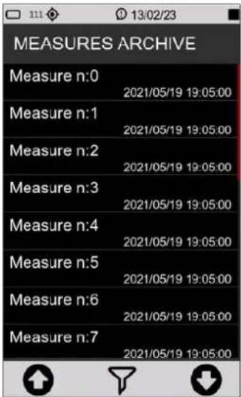 |
| 4 If necessary, press the central icon (FILTER)5 Enter the search string in the field to display only specific measurements6 Tap the central icon in the control bar to confirm the display filter settings and access the filtered list | 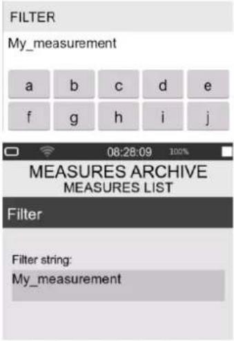 |
| 7 Use the arrows (UP/DOWN) and the central icon (OK) to access the measurement data management menu.8 Tap LOAD FILE to access the data table display panel (only the main parameters of the globals.dodl group can be displayed)9 Tap BACK to return to the measurement list | 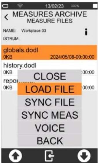 |
11.3.2 Manual cloud synchronisation of data files
Synchronisation consists in sending all or part of the measurement data contained in the archive to the Noise Studio Cloud Storage service. In order to synchronise data directly from the device, it is necessary that the instrument, equipped with the OF5S option, is connected to the service via the Wi-Fi communication device (or LAN or 4G if available) and access to the service via credentials is made (see "11.4.2 Data storage on Cloud" on page 84).
| 1 SelectSYNC FILEto upload the individual measurement file to the cloud * (ie. globals.dodl or history.dodl ecc.)2 SelectSYNC MEASto send the folder containing all files to the cloud. (ie. My_Measurement)3 Check on the status bar the icon indicating that synchronisation is in progress | 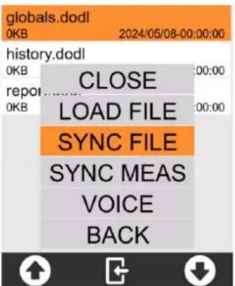 |
* Each measurement file is identified by a unique ID that allows measurements sent to the cloud at different times to be correctly grouped together
11.3.3 Entering a voice note to the measurement
It is possible, from the measurement Archive, to associate a voice comment to measurements after they have been completed. The comment is stored in wav format (file name voice.wav) within the folder relating to the measurement.
1 Select VOICE to enter a voice note to the measurement
2 In the control bar, tap the record button and speak into the microphone
3 Press the STOP button to end the voice note
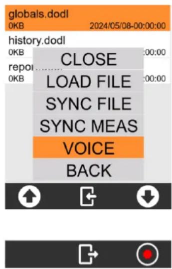
11.3.4 Renaming and deleting a data file

Notice!
It is not possible, from the user interface, to rename and delete measurement data files. For this purpose, use a PC and access the storage drive via USB. See section "11.4.1 Saving on PC" on page 84.
11.4 Saving of data files
The standard storage format of the XPT800 sound level meter is *.dodl (proprietary format). Files of type dodl contain information in binary format that cannot be read directly. To read the information, it is necessary to convert the dodl format via a converter (parser) integrated in the NS-Storage portal (https://noise-studio.senseca.com/) available to Senseca sound level meter owners. Once converted via the parser, the data can be viewed directly on the NS Web Storage portal and can be exported in text or Excel formats. From the NS Web Storage portal, data can be imported into data analysis software modules such as NS-ENS. For specific applications, a local parser can be provided, e.g. for the exclusive use of Public Administrations or organisations with specific data privacy requirements.
11.4.1 Saving on PC
Connect the XPT800 instrument to a PC (Windows and Mac) using a USB-C cable connected to its connector.
Now the instrument will be visible as a peripheral drive, you can manage your recording data files.

Info
Refer to chapter "12 Network and connections" on page 86 to make the connection properly.
11.4.2 Data storage on Cloud
It is possible to upload measurement data files to the NS Cloud Storage service. There are two ways of uploading from DEVICE directly or from a PC.
From DEVICE
Automatically ("11.4.3 Automatic cloud synchronisation of data files via Push option") or manually by selecting the measurement from the measurement archive ("11.3.2 Manual cloud synchronisation of data files"), the instrument uploads the measurements to the NS-Storage portal.
From PC
Selecting individual dodl files or complete folders containing measurements (dodl, wave, etc.) directly from the instrument's eMMC memory or from files stored on a PC and uploading the measurements to the NS-Storage portal.
To upload in manual mode, it is necessary to:
• have a PC connected to the Internet.
• have saved files on the PC or on an external drive connected to the PC.
• have an e-mail address.
- log on to https://noise-studio.senseca.com/ and follow the registration procedure via the e-mail address.
Once the workspace has been accessed, it is possible to upload the measurement data files.
1 Select the 'File' panel.
2 Fill in the mandatory fields marked with an asterisk:
- session name prefix: enter the name you wish to assign to the recording;
- choose the time zone of the recording location.
3 Select a single file or a directory to upload several files simultaneously.
4 Press "Upload", if the upload was successful, the message "File successfully uploaded" will appear
11.4.3 Automatic cloud synchronisation of data files via Push option
To upload in push mode, it is necessary to:
• have OF5S option active on the device
- have internet access via WiFi, 4G or Ethernet cable, see the relevant chapters “12.2 Connecting to a WiFi network” on page 86 and “12.3 Connecting to an Ethernet port” on page 88
- Tap the icon on the drop-down menu.
- In SETTINGS > DATALOGGER > SETUP: Sync files select the file types to be synchronised among: REPORTS, EVENTS, GLOBAL, AUDIO
12 Network and connections
12.1 Network Settings
In order to be connected to the Internet, the instrument must be activated by the manufacturer via the NS-Devices service. The (editable) URL of the site accessed by the device is set as a default parameter directly in the network settings of the instrument.
12.2 Connecting to a WiFi network
To configure and connect the instrument to an existing WiFi network, proceed as follows:
| 1 Tap the icon in the status bar to activate Wi-Fi |  |
| 2 In the ICON MENU, press the SYS-FUNC icon to access the system app menus.3 Access the NETWORK CONNECTION page and press on 4 WIFI to access the WIFI Setup page. | 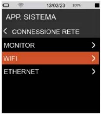 |
| Scan panelIn this panel, available access points are detected.1 Press the SCAN button to scan for available access points.2 Click on one of the displayed access points to access the Access point setup panel for SSID configuration, security, and password entry.3 Press the button to confirm. The selected access point is entered into the "Access Points" panel and stored in a list. The user has the option of removing or changing the access points in the list. | 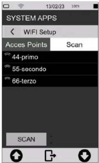 |
Access Points panel
The names of the access points stored from the 'Scan' panel appeal in this panel..
4 Select an access point, press the buttons to perform the desired operation:
= press the button to connect the device to the selected access point. Within the list, successful connection is indicated by an icon at the selected network. In the status bar, successful access to the network is indicated by the active Wi-Fi icon, which also indicates the level of the available signal. The presence of a padlock next to the Wi-Fi icon indicates that the network is protected.
= press the button to access the panel for configuring SSID, Security and entering the password of the selected access point
= press the button to remove the selected access point from the list, to retrieve it the scan must be performed again
= press the button to move the selected access point to the top of the list.
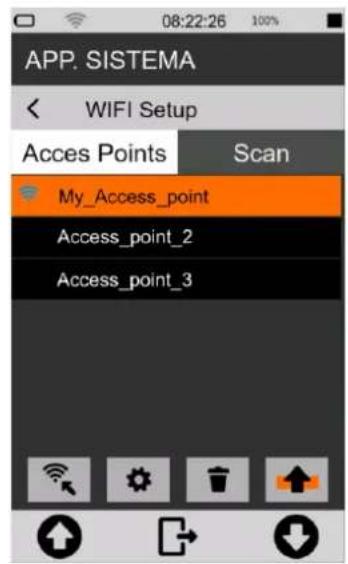

Info
Should the active access point be switched off or no longer available, an automatic search for a connection to the first available access point from the top of the list will be carried out.
Access points setup panel
5 tap on the fields to activate the keyboard and type in the credentials of the network you want to use.
6 Press √ to confirm, press ✗ to cancel operation

Info
For details on using the keyboard see chapter "4.10 Entering text and numbers" on page 26.
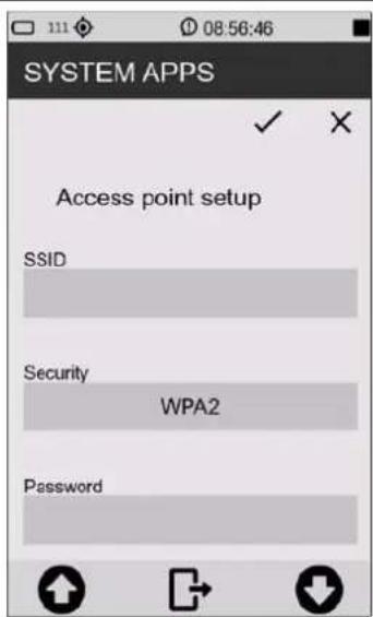
12.3 Connecting to an Ethernet port
Through the Ethernet port (port availability depending on options), it is possible to connect the device to the internet using the RJ45 port of the network adapter as a connection device.
To connect the XPT800 to an Ethernet port, follow these steps:
1 Make sure you have the following equipment:
• LAN socket on the instrument (opz.OH3B);
- Ethernet cable;
- a functional Ethernet network port.
2 Connect the XPT800 instrument to a network using the Ethernet cable plugged into the LAN socket.
3 From the drop-down menu, tap the icon 📋 to select the connection device. The successful activation of the interface is indicated by the blue icon; other network interfaces are disabled.
4 Wait until the 'LAN' icon 📁 appears in the status bar, indicating successful connection.

Info
For details on the instrument's network settings, please refer to chapter "12.1 Network Settings" on page 86.

Notice!
Ethernet connections use a lot of energy. It is recommended to also connect the instrument to an external power source via USB while connected.
12.4 Connecting through GSM network \*
To set up and connect the instrument to a GSM network, follow the steps below:
| 1 tap the Modem icon in the drop-down menu. | 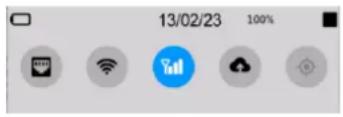 |
* Planned Functionality
12.5 Connecting to a PC with USB interface
Connect the XPT800 instrument to a PC (Windows and Mac) using a USB-C cable connected to USB connector. The instrument will now be visible as a memory unit.
It's possible to:
• View system files (System)
• display and copy measurement data files (Measure)
• view configurations (Setup)
• view playback files (Traces)
13 Firmware update and options
The firmware, i.e. the program that manages all the instrument's functions, can be updated by transferring the file from a PC to the XPT800 via the USB-C ports. This allows the functionality of the instrument to be updated.
To proceed with the update, use the FW UPGRADE function accessible from the SYS-FUNC icon.

Warning!
During the procedure the power supply status must be sufficient to perform the update.
- With external power supply, DO NOT remove the power cable until the firmware update is complete.
- With battery power, the battery must be close to 100% to ensure that the boot-loader functions are not interrupted and thus avoid possible FLASH memory write errors.

Info
The BL (boot-loader) accepts that there are also other files in the 'firmware' directory. The files will be evaluated starting with the extension ".hex", then whether the attribute "archive" is set, and finally the contents of the APP table "infoAPP" contained in the file. If there is more than one file in the directory that meets these requirements, the first one proposed by the file manager will be used for update.
13.1 Firmware version
To find out the firmware version installed in the instrument.
| 1 In the ICON MENU, press the SYS-INFO icon to access the system information and monitor menus.2 Tap to access theFIRMWAREpage. | 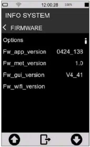 |
13.2 Firmware update
Updating the firmware requires a PC with a USB port and the file containing the new firmware. Firmware files are of the type:
file_name.hex
| 1 Turn on and connect the XPT800 Sound Level Meter to the USB port of your PC using USB-C cable.2 In SYS-FUNC/USB/PROCEDURES press FILE WRITE to activate USB write (don't exit the pop-up!)3 As soon as access to the memory unit is available, copy the "new_firmware.hex" file to the folder > Firmware.4 On the FILE WRITE pop-up press EXIT to deactivate USB write5 Switch the instrument off and on again6 In ICON MENU, press the SYS-FUNC icon to access the system and measurement configuration menus.7 Access the FW UPGRADE and PROCEDURES pages in succession.8 Tap on LOAD NEW. |     |
The device automatically reboots until the splash screen is displayed; the status LED starts blinking green. The update procedure can take between 10 and 20 minutes.
Verify the correct update of the new version as described in chapter "13.1 Firmware" on page 90.

Info
In the case that the update cannot be carried out, e.g. due to a battery voltage below 3.8V, a running measurement, or a missing correct .hex file, a pop-up alerts the user with a message.

Notice!
- In the event that the firmware update fails, the status LED turns red, indicating a possible error in the upload procedure...
- The instrument has a recovery firmware pre-loaded in a non-editable memory area; to restore the firmware, please refer to section "13.3 Instrument recovery via recovery firmware" on page 93.
13.2.1 Wi-Fi firmware update
Updating the Wi-Fi firmware requires a PC with a USB port and the file containing the new firmware. Wi-Fi firmware files are of the type:
file_name.glb
| 1 Turn on and connect the XPT800 Sound Level Meter to the USB port of your PC using USB-C cable.2 In SYS-FUNC/USB/PROCEDURES press FILE WRITE to activa USB write (don't exit the pop-up)3 As soon as access to the memory unit is available, copy the "new_firmware.glb" file to the folder > Firmware.4 On the FILE WRITE pop-up press EXIT to deactivate USB write5 Switch the instrument off and on again6 In ICON MENU, press the SYS-FUNC icon to access the sys-tem and measurement configuration menus.7 Access the FW UPGRADE and PROCEDURES pages in suc-cession.8 Tap on LOAD NEW. |      [HSAX] [HSAX] |
The device automatically reboots until the splash screen is displayed; the status LED starts blinking blue. The Wi-Fi update procedure can take a couple minutes.
Verify the correct update of the new version as described in chapter “13.1 Firmware version” on page 90.

Info
In the case that the update cannot be carried out, e.g. due to a battery voltage below 3.8V, a running measurement, or a missing correct .glb file, a pop-up alerts the user with a message.

Notice!
- If the firmware update fails, the status LED flashes red five times, indicating a possible error in the charging procedure...
- The instrument has a recovery firmware pre-loaded in a non-editable memory area; to restore the firmware, please refer to section "13.3 Instrument recovery via recovery firmware" on page 93.
13.3 Instrument recovery via recovery firmware
If the firmware update fails, the instrument has a recovery firmware pre-loaded in a non-editable memory area.
The recovery firmware can be reloaded if necessary to restore the instrument.
| 1 In the ICON MENU, press the SYS-FUNC icon to access the system and measurement configuration menus. 2 Access FW UPGRADE and PROCEDURES. 3 Press LOAD STABLE. | SYSTEM APPS FIRMWARE UPGRADE LOAD NEW LOAD STABLE |
13.4 Enabling or disabling options
The XPT800 allows new options to be installed without the instrument having to be sent to the manufacturer for upgrade. Contact the sales department for more information.
To check the options installed on your device and those that can be installed, proceed as follows:
| 1 In the ICON MENU, press the SYS-INFO icon to access the system information and monitor menus. 2 Access the FIRMWARE menu. Tap on Options to display the list of options active on your device and those that can be purchased and activated | INFO SYSTEM FIRMWARE Options Fw_app_version 0424_138 Fw_met_version 1.0 Fw_gui_version V4_41 Fw_wifi_version |
14 Maintenance Operations
14.1 Cleaning the Instrument
Clean the device with a soft, clean cloth or, when necessary, slightly moistened with clean water.

Warning!
Take care that no moisture enters the enclosure.

Forbidden!
Do not use sprays, solvents, alcohol-based cleaners or abrasives.
14.2 Microphone cleaning (microphone diaphragm)
To avoid permanent alterations in frequency response and consequent degradation of performance that may invalidate the instrument's compliance with class 1 tolerance limits, the accumulation of dust and dirt particles on the microphone diaphragm must be avoided.
The microphone capsule and diaphragm must be periodically inspected and, if necessary and possible, cleaned. Inspection and cleaning, if necessary, are normally carried out during periodic calibration at the accredited Senseca Italy Srl laboratory.
14.3 Accredited periodical calibration
This must be performed at Senseca Italy's UNI CEI EN ISO/IEC 17025 accredited laboratories or at another accredited laboratory for the calibration of sound level meters and octave or third octave filters.
Periodic calibration must be carried out in accordance with international technical standards.

Notice!
It is recommended to calibrate the unit annually.
15 Troubleshooting Guide
15.1 Formatting eMMC memory (FORMAT)

Warning!
Before formatting, all folders in the eMMC memory must be backed up.
Formatting the eMMC memory results in the deletion of the following contents:
- microphone serial number
- system configuration
- access points configurations
• measurement setups in APPLICATION MANAGER - stored measurement data
- generator files
- audio tracks
- calibration history
- any firmware files (*.hex) loaded in the relevant folder
Two equivalent formatting modes are possible:
- formatting from device
- formatting from PC
Formatting from device
| 1 In the ICON MENU, press the SYS-FUNC icon to access the system configuration and measurement menus.2 Access the INITIALISATION and PROCEDURES pages in succession.3 Press on FORMAT. To confirm the operation, press OK, to cancel press CANCEL. | 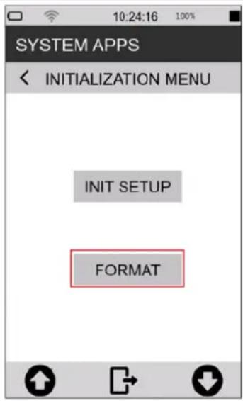 |
Formatting from pc
The eMMC memory is recognised by the PC as an external drive with the XPT800 model name. The format command available on Windows determines the formatting of data and settings as described in the warning at the beginning of the paragraph. On the next reboot, the sound level meter's operating system restores the device's default settings (please note that the microphone serial number must be restored. See XPT80X_SLM_Config).
Formatting details:
- Format: exFAT
• Size of allocation unit: 32kilobyte - Label: XPT800
15.2 Restoring Parameters to Default Settings (Reset)
Resetting the settings resets the setup parameters to the default settings.

Warning!
The Reset procedure, if a formatting has been performed, does not restore all previous conditions.
The reset procedure does not delete:
- Measurement data files (unit:\XPT800_xxxxxxxxxx\Measure)
- Measurement settings (unit:\XPT800_xxxxxxxxx\Setup)
- Calibration history
To perform a reset, follow this procedure:
1 Ensure that no measuring and recording is in progress.
2 Make sure you have saved any configurations being edited in APPLICATION MANAGER.
| 3 In the ICON MENU, press the SYS-FUNC icon to access the system configuration menus.4 Access the INITIALISATION and PROCEDURE pages.5 Touch on INIT SETUP. To confirm the operation, press OK, to cancel press CANCEL. | 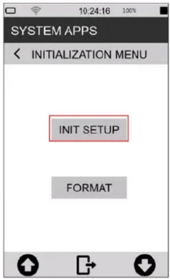 |
15.3 Malfunctions, causes and possible solutions
◆ Calibration procedure fails:
The calibration correction is applied and written in the Curr.Att. field, along with the date and time, only if it is within the expected range. If the calibration procedure fails, the correction is not applied and written.
Failure to apply the correction may be due to the following factors:
- microphone out of nominal specification
• sound calibrator out of nominal specification
• acoustic calibrator off or with incorrect level setting - expected calibration value (expected field) not set correctly with respect to the calibrator used.
Possible solutions:
- Ensure that the instrument is not exposed to high noise and/or vibration and that the acoustic calibrator and sound level meter are firmly aligned, and the microphone is fully inserted into the calibrator cavity.
- Check that the rubber sealing ring inside the calibrator cavity is not damaged and is correctly positioned.
- Repeat after waiting for the end of the stabilization time.
❖ The sound levels measured by the sound level meter appear to be incorrect:
- Check that the preamplifier is fully inserted into the connector on the sound level meter (the push-pull connector "clicks" when correctly inserted).
- Ensure that the microphone capsule is correctly screwed onto the microphone preamplifier.
- Verify that there is no dirt on the microphone protection grid.
- When using a microphone extension cable, try connecting the preamplifier directly to the sound level meter, excluding the cable as a possible cause of malfunctioning.
- Check that the displayed acoustic parameter is correct (we recommend using an instantaneous parameter such as LAFp)
- Check that the microphone protection grid is screwed tightly onto the capsule.
- Ensure that there is no condensation on the microphone capsule or preamplifier. Avoid switching on the sound level meter in conditions where condensation may occur. For measurements in high humidity or rain, use the WSO outdoor microphone protection unit.
- Activate the preamplifier heater.
❖ The sound level meter switches off immediately after the power-up presentation screen:
- Battery is depleted and must be charged, use external power supply as an alternative.
❖ The sound level meter does not communicate with the PC:
- Check that the connection cable is correctly plugged into the USB-C connector on the sound level meter and that it is connected to a USB socket on the PC.
- If the USB interface is used, check that, on the sound level meter, are not activated functions for which the USB port is to be disabled (e.g. Log_Sync or measurement with storage).
✿ Continuous logging cannot be activated. The instrument starts measurements without data recording:
- Out of memory. Download data and/or delete memory.
❖ Manual audio recording does not work:
- Check that the audio logging mode is on TRG (EDIT APP > LOG > AUDIO > Audio logging = TRG).
❖ Automatic audio recording does not start:
- Check that the audio logging mode is on TRG (EDIT APP > LOG > AUDIO > Audio logging = TRG).
- Verify trigger input (EDIT APP > TRIGGER > INPUT > SLM = activate check box for parameter on which trigger thresholds are set).
- Check the activation thresholds values by tapping on the parameter selected for triggers in the SLM screen.
16 Long-term storage
- Switch off the instrument as indicated in chapter "6.3 Switching off" on page 40.
- If the instrument is to be stored for more than 2 weeks, remove the battery as indicated in chapter "5.5.3 Battery insertion and replacement" on page 37.
• We recommend storing the instrument in its case and in a dry environment.

Warning!
In case the instrument is externally powered or charging, do not remove the power cord before turning off the instrument. Removing the power cable with the instrument still on, could result in the loss of unsaved data.
17 Spare parts
For spare parts, please contact Senseca Italy Srl or an authorised dealer.
| Codice | Descrizione |
| ANTGSM8 | External Antenna for GSM module |
| BAG8 | Rugged carrying case (standard version) 335 x 295 x 122 mm |
| BAG8K | Rugged carrying case (big version) 465 x 355 x 145 mm |
| BAT8 | Rechargeable lithium battery 9Ah |
| BATLID8 | Battery compartment lid |
| LID8 | Rubber cap protecting the connector panel with Senseca logo |
| MC800 | Precision microphone (class 1) |
| MP800 | Single-range microphone preamplifier |
| WSO | Outdoor microphone protection |
| WS90 | Windshield (90 mm) for 1/2" microphones. |
18 Appendix A - Technical Specifications
| Inputs | Microphone | MC800: Free field 1⁄2", 50 mV/Pa sensitivity; 0V; IEC 61094-4 WS2F, 3.15Hz-20KHz.MP800: preamplifier, automatic detection of model and calibration data.SDI (Sensor Digital Interface). CTC automatic electric calibration |
| Accelerometer | IEPE, 4-pin circular push-pull, tri-axial | |
| Measuring ranges with MC800 microphone MP800 preamplifier | Dynamic range Linear Operating Range | >125dB A (1kHz) 20 dB - 137 (140pk) C 22 dB - 137 (140pk) Z 25 dB - 137 (140pk) |
| Frequency weightings | A, C + B or Z (user selection). 3 simultaneous | |
| Time constants | Fast, Slow, Impulse, Peak simultaneous | |
| Averaging | Linear, exponential, moving, max, min | |
| Parameters* | Lp, Leq, Lleq, SEL, Leq_mov (Sliding), L_min/max , L_peak , Level diff. (i.e. LCeq-LAeq), LUp, LUeq (User between two sel.bands), LAFT, LAFTeq (TaktMax), L_PER ( L_den , L_dn , L_day , L_evening , L_night ), Lp^1/1 , Lp^1/3 , Leq^1/1 , Leq^1/3 , Leq_mov^1/1 , Leq_mov^1/3 , Ln (0.1%-99.9%), Ln_mov , Ln^1/1 , Ln^1/3 , pL, pL^1/3 *For more details about measurement parameters see Appendix B | |
| Spectral Analysis | Octave | Real time, 1/1 octave, 8Hz to 16kHz, IEC 61260-1:2014 Real time, 1/3 octave 6.3Hz to 20kHz, IEC 61260-1:2014 |
| FFT | Real time FFT in parallel with 1/3 oct. (specifications TBA) | |
| Noise Criteria | NC, NR, RNC, RC | |
| Reverberation time | T60 calculation | |
| Intelligibility | STI/STIPA | |
| Statistical Analysis | Broad band and Spectral: 7xLn (Lin and Mov) selectable percentile levels (0.1%-99.9%). Probability/Cumulative distribution | |
| Audio | Recording | Mode: continuous, manual or event triggered. Resolution 16, 24, 32-bit. Audio-band: 10, 20 KHz. Format: Wave or compressed (ADPCM) |
| Playback | Embedded codec for signal generation. Playback channels: Generator, Trace (.wav) or Measurement (Mic input). Playback Mic or Mic-filtered (Wide Band A, C, Aux or 1/3 band selectable) for Audio playback of microphone input. | |
| Measurement Control | Start, stop, pause, reset, back-erase, continue, event marking, manual audio recording.Measure timer from 1s to 23:59:59 hrs | |
| Calibration | Acoustic | Manual or automatic (tone detection). Calibrations history: date/time, dB correction.Free Field, Random Incidence, environmental and shield corrections |
| Vibration Measurements | Triaxial vibration | Human exposure to hand-transmitted vibration (ISO 5349) Human exposure to whole-body vibration (ISO 2631-1) Human exposure to whole-body vibration in buildings (ISO 2631-2) |
| Triggers | Broad band | Single or multiple (OR/AND) on broad-band levels, levels difference, Ln, Lmov |
| Spectra | On 1/1 or 1/3 oct. masks. Single - All bands mode. Max, min thresholds editable (man or json file) | |
| Detectors | Tonality | Automatic identification according to DM 16/03/1998 and ISO1996-2 |
| Impulsivity | Automatic identification according to DM 16/03/1998 | |
| Storage | Physical | Embedded 4GB eMMC and up to 64GB μSD (TBA); USB memory stick. |
| Cloud | Upload to cloud storage service (NS-Storage). Manual or automatic (Push) | |
| Archive | List and preview of stored data. Manual data upload on NS-Storage cloud service. | |
| Datalogging | Time history: independent Short, Standard, Report steps.Short: 10ms. Standard: 100/200/500ms/1s.Reports: 10/20/30s,1/2/5/10/20/30/60mEvents: triggered broad-band, octave, Ln valuesGlobals: Continuous, Daily integrations | |
| Display | 4.3" touch, 480x800px, colour TFT, high brightness, sunlight readability. Auto brightness. | |
| Keyboard | ON/OFF/MENU key with RGB backlight; Function keys (2x); Multi-colour Status Indicator. | |
| Battery | Type | Rechargeable battery pack, Li-Ion polymer, 9000mAh. PCM circuit for battery protection |
| Operating time | >24h | |
| Wireless | Wi-Fi | Embedded Wi-Fi module (IEEE 802.11 b/g/n), for web communication and time sync |
| GSM | Embedded 4G-LTE modem module for web communication and time sync | |
| Hardware interface | USB-C | USB-C, OTG 2.0. MS (Mass Storage) and CD (Communication Device) |
| Ethernet | RJ45 10/100 Ethernet for web communication and time sync | |
| Aux | RJ12: auxiliary connector for external devices as Meteo stations (Meteo interface) | |
| Audio I/O | 3.5mm 4-pin audio jack: audio I/O and trigger I/O | |
| Localization | GPS | Location tracking, time synchronization |
| Physical | Dimensions: 304x86x38 mm. Weight: 505 g (incl. batteries). Dust and water-resistant case (IP Rating pending). Standard 1⁄4 tripod mount thread. | |
| Language | English, Italian (others TBA) | |
| System | Status bar | Battery, GPS, Wi-Fi/Lan/4G conn., Cloud conn.level, uload/dload, notifications, date/time, active storage media, remaining storage, overload/underload, audio recording, active measurement mode |
| Monitor | Battery level [%], device temp [°C], pressure [hPa], charge voltage, pre temp [°C] | |
| Fw/Options upgrade | Via USB connection or Over-the-air (OTA) updates of firmware and new options. | |
| Acoustic Standards | IEC | Sound Level MeterIEC 61672-1 (2013) class 1IEC 60651 (1979) plus Amendment 1 (1993-02) Amendment 2 (2000-10), type 1IEC 60804 (2000-10) type 1Octave and fractional octave band filtersIEC 61260-1 (2014) |
| ANSI | Sound Level MeterANSI S1.4-1983 plus ANSI S1.4A-1985 Amendment type 1 (sound level meter)ANSI/ASA S1.4-2014 class 1ANSI S1.43-1997 type 1Octave and fractional octave band filtersANSI/ASA S1.11-2014 Part 1 | |
| Software | Desktop | Noise Studio NS-ENS: environmental noise analysisNoise Studio NS-SIS: buildings acoustic performance analysis |
| Web applications | Noise Studio NS-Storage: storage and display of measurement dataNoise Studio NS-Manager: remote management of compatible devicesNoise Studio NS-Monitor: remote management of compatible devices |
Note (for more information contact sales department):
- some hardware and firmware features may be subject to the purchase of specific options
- some features may be under development (planned) and available later (TBA)
| 4.3" color active matrix TFT display with RGB and SPI interfaces | |
| Panel | IPS transmissive type |
| Touch panel | 5 points + gestures |
| Size | portrait oriented 56.16 mm x 93.60 mm active area |
| Resolution | 480 x 800 pixels |
| Colors | 65K / 262K / 16.7M colors |
| Viewing quality | free viewing direction up to angles higher than 80°, bright enhancement and high reflectivity film |
| Contrast | 800 typical |
| Luminance | 600 cd/m2 typical |
| Readability | good even under sunlight thanks to high brightness led chips, BEF (Bright Enhancement Film) and OCA bonding |
| Cover glass | 6H tempered glass, 1.1mm thickness, OCA (Optical Clear Adhesive) glue, custom shaped with company logo |
| Mounting features | 3M VHB 5980 tape (waterproof) |
| Operating temperature | -20°C ÷ +70°C |
| Storage temperature | -30°C ÷ +80°C |
| Interfaces | RGB 16/18/24-bit and SPI |
19 Appendix B - Parameters
19.1 Measure Parameters
The acoustic parameters that can be calculated by the XPT800 sound level meter are defined in "Classes". Each Class can assume specific values of the variables "Time Constant", "Weighting", "Band" of measurement, "Type".
19.1.1 Parameters Classes
| Class | Time constant (Y)/Integration | Ponderation (X) | Band | Description |
| LXFp | FAST | A, C, AUX (Z, B) | Broadband | Sound pressure level with constant FAST |
| LXSp | SLOW | A, C, AUX (Z, B) | Broadband | Sound pressure level with constant SLOW |
| LXIp | IMP | A, AUX (B, C, Z) | Broadband | Sound pressure level with constant IMPULSE |
| LXeq | LIN | A, C, AUX (Z, B) | Broadband | Equivalent sound pressure level |
| LXeqm | LIN | A, C, AUX (Z, B) | Broadband | Equivalent sound pressure level with "moving" integration |
| LXleq | IMP | A, AUX (B, C, Z) | Broadband | Equivalent sound pressure level with constant IMPULSE |
| LXpk | NONE | C, AUX (A, B, Z) | Broadband | Peak sound pressure level |
| LXOYp | FAST, SLOW | A, C, OFF | Octave band filters | Octave band spectrum of sound pressure level. Bands from 8Hz to 16kHz |
| LXOeq | LIN | A, C, OFF | Octave band filters | Octave band spectrum of the equivalent sound pressure level. 8Hz to 16kHz Bands |
| LXOeqm | LIN | A, C, OFF | Octave band filters | Octave band spectrum of the equivalent sound pressure level with "moving" integration. 8Hz to 16kHz bands |
| LXTOYp | FAST, SLOW | A, C, OFF | Third Octave band filters | Third-octave band spectrum of sound pressure level with FAST or SLOW constant. 6.3Hz to 20kHz bands |
| LXTOeq | LIN | A, C, OFF | Third Octave band filters | Spectrum for one-third octave bands of the equivalent sound pressure level. Bands from 6.3Hz to 20kHz |
| LXTOeqm | LIN | A, C, OFF | Third Octave band filters | Spectrum for third-octave bands of the equivalent sound pressure level with "moving" integration. 6.3Hz to 20kHz Bands |
| LXper | per | A, C | Broadband | Equivalent sound pressure levels with Day, Evening and Night integration. Sound Levels Lden and Ldn |
| LXYn | LIN, FAST, SLOW | A, C, AUX (Z, B) | Broadband | Percentile sound pressure levels. 7 user-defined levels are calculated |
| LXYnm | LIN, FAST, SLOW | A, C, AUX (Z, B) | Broadband | Sound pressure percentile levels with "moving" integration. 7 user-defined levels are calculated |
| LXTOYn | FAST, SLOW | A, C, OFF | Third Octave band filters | Percentile sound pressure levels for third-octave spectrum bands. Seven user-defined levels are calculated |
| pLX | LIN, FAST, SLOW | A, C, AUX (Z, B) | Broadband | Sound pressure level statistics. 241 classes of 0.5dB are calculated |
| pLXTO | FAST, SLOW | A, C, OFF | Third Octave band filters | Statistics of sound pressure levels of the third-octave spectrum. 121 classes of 1.0dB are calculated |
| LUXYp | FAST, SLOW | A, C, OFF | Between two 1/3 bands | Sound pressure level integrated by the spec-trum for third-octave bands, according to user-defined limits |
| LUXeq | LIN | A, C, OFF | Between two 1/3 bands | Equivalent sound pressure level integrated from the bore for third-octave bands, according to user-defined limits. |
| LXE | LIN | A, C, AUX (Z, B) | Broadband | Exposure level (SEL) |
| LAFT | FAST | A | Broadband | Takt-max level integrated over a user-defined interval (3s or 5s) |
| LAFTeq | LIN | A | Broadband | Takt-max equivalent level |
19.1.2 Composition of Acoustic parameters Labels
The calculated acoustic parameters, belonging to the parameter classes in the table above, are uniquely identified by labels. The same syntax is used for parameter representation in both the XPT80X sound level meter interface and the NS-Storage and NS-ENS software applications.
Description of acoustic parameter labels
| Label | Description |
| L | Level |
| X | Frequency weighting filter ("" = no filter : filter = off) |
| Y | Time constant |
| TO | Third-octave band filter |
| O | Octave band filter |
| p | Sound pressure level |
| n | Statistical percentile level |
| per | Period level (day, evening, night) |
| pL | Probability of levels |
| eq | Equivalent level |
| pk | Peak level |
| E | Exposure level (SEL) |
| m | Level with moving average |
| U | User level (global level between two selectable frequency bands) |
| FT | Takt-max level |
Acoustic parameter label variables
| Type | Label | Description |
| INST | “ “ | Instantaneous sampled @ step interval |
| AVG | “,T” | Equivalent integrated in measurement time T |
| MAX | “,mx,T” | Max. in measurement time T |
| MIN | “,mn,T” | Min in measurement time T |
| INT | “,t” | Equivalent integrated in Report time interval t |
| INTMAX | “,mx,t” | Max in report time interval t |
| INTMIN | “,mn,t” | Min in report time interval t |
| EV | “,Te” | Equivalent integrated in event time interval Te |
| EVMAX | “,mx,Te” | Max in event time interval Te |
| EVMIN | “,mn,Te” | Min in event time interval Te |
| SHORT | “ “ | Instantaneous sampled every 10ms |
| TAKTMAX | “ “ | Taktmax integrated on takt interval |
Acoustic Parameter labelling example
The label that uniquely identifies the specific acoustic parameter is generated from the variables indicated above, as in the example below, where the labels of some measurement parameters are shown.
| Label | Class | Type | Time constant (Y)/Integration | Ponderation (X) | Band |
| LAFp | LXFp | INST | FAST | A | Broadband |
| LAeq,T | Lxeq | AVG | LIN | A | Broadband |
| Lceq,t | Lxeq | INT (Report) | LIN | C | Broadband |
| LZSp,mx,T | LXFp | MAX | SLOW | Z | Broadband |
| LZTOeq,T | LXTOeq | AVG | LIN | Z | Third Octave band |
19.1.3 Classes of measurement parameters available for visualisation
The following table shows the classes of parameters that can be displayed in the different screens available in the Graphic User Interface.
| Class | SLM | TABLE WB | TABLE OCT | TABLE TOCT | GRAPH | HISTOGRAM |
| LXFp | √ | √ | - | - | √ | - |
| LXSp | √ | √ | - | - | √ | - |
| LXIp | √ | √ | - | - | √ | - |
| LXeq | √ | √ | - | - | √ | - |
| LXeqm | √ | √ | - | - | √ | - |
| LXleq | √ | √ | - | - | √ | - |
| LXpk | √ | √ | - | - | √ | - |
| LXOYp | √ | - | √ | - | √ | √ |
| LXOeq | √ | - | √ | - | √ | √ |
| LXOeqm | √ | - | √ | - | √ | √ |
| LXTOYp | √ | - | - | √ | √ | √ |
| LXTOeq | √ | - | - | √ | √ | √ |
| LXTOeqm | √ | - | - | √ | √ | √ |
| LXper | √ | √ | - | - | √ | - |
| LXYn | √ | √ | - | - | √ | - |
| LXYmn | √ | √ | - | - | √ | - |
| LnXTOY | - | - | - | √ | - | - |
| pLXY | - | - | - | - | - | - |
| pLXTOY | - | - | - | - | - | - |
| LUXYp | √ | - | - | - | √ | - |
| LUXeq | √ | √ | - | - | √ | - |
| LXE | √ | √ | - | - | √ | - |
| LAFT | √ | - | - | - | √ | - |
| LAFTeq | √ | √ | - | - | √ | - |
19.1.4 Classes of measurement parameters available for storage
The following table shows the classes of parameters that can be logged in the different storage modes provided, corresponding to specific *.dodl files generated through the logging settings (see 9.4 Set acoustic parameters to be stored on page 55).
| Class | T.HISTORY | REPORTS | EVENTS | GLOBALS |
| LXFp | √ | √ | √ | √ |
| LXSp | √ | √ | √ | √ |
| LXIp | √ | √ | √ | √ |
| LXeq | √ | √ | √ | √ |
| LXeqm | √ | √ | √ | √ |
| LXIeq | √ | √ | √ | √ |
| LXpk | √ | √ | √ | √ |
| LXOYp | √ | √ | √ | √ |
| LXOeq | √ | √ | √ | √ |
| LXOeqm | √ | √ | √ | √ |
| LXTOYp | √ | √ | √ | √ |
| LXTOeq | √ | √ | √ | √ |
| LXTOeqm | √ | √ | √ | √ |
| LXper | √ | - | - | √ |
| LXYn | √ | √ | √ | √ |
| LXYnm | √ | - | - | - |
| LnXTOY | - | √ | √ | √ |
| pLXY | - | √ | √ | √ |
| pLXTOY | - | √ | √ | √ |
| LUXYp | √ | √ | √ | √ |
| LUXeq | √ | √ | √ | √ |
| LXE | √ | √ | √ | √ |
| LAFT | √ | - | - | - |
| LAFTeq | √ | - | - | √ |
19.1.5 Types of parameters available for screens (views)
The following table shows the types of parameters that can be displayed in the different views available in the graphical user interface.
| TYPE | SLM | TABLE WB | TABLE OCT | TABLE TOCT | GRAPH | HISTOGRAM |
| INST | √ | √ | √ | √ | √ | √ |
| AVG | √ | √ | √ | √ | √ | √ |
| MAX | √ | √ | √ | √ | √ | √ |
| MIN | √ | √ | √ | √ | √ | √ |
| INT (Report) | - | TBA | √ | √ | - | √ |
| INTMAX(Report max) | - | TBA | √ | √ | - | √ |
| INTMIN(Report min) | - | TBA | √ | √ | - | √ |
| EV (Evint) | - | TBA | √ | √ | - | √ |
| EVMAX (Evint max) | - | TBA | √ | √ | - | √ |
| EVMIN (Evint min) | - | TBA | √ | √ | - | √ |
| SHORT | - | - | - | - | - | - |
19.1.6 Types of parameters available for storage
The following table shows the types of parameters that can be recorded in the different storage modes available.
| TYPE | T.HISTORY | REPORTS | EVENTS | GLOBALS |
| INST | √ | - | - | - |
| AVG | √ | - | - | √ |
| MAX | √ | - | - | √ |
| MIN | √ | - | - | √ |
| INT (Report) | - | √ | - | - |
| INTMAX (Report max) | - | √ | - | - |
| INTMIN (Report min) | - | √ | - | - |
| EV (Evint) | - | - | √ | - |
| EVMAX (Evint max) | - | - | √ | - |
| EVMIN (Evint min) | - | - | √ | - |
| SHORT | √ | - | - | - |
| TAKTMAX (Tmax) | √ | - | - | √ |
19.2 Setup Parameters
The following table shows the names of the setup parameters, the menu position, the description and the range of possible values for the user setting.
| PARAMETER | MENU | DESCRIPTION/RANGE |
| Meas. setup version | SETT.../INSTRUMENT/IDENTIFICATION | Version set-up measures |
| Instr. model | SETT.../INSTRUMENT/IDENTIFICATION | Instrument model: XPT800, XPT801 |
| Instr. serial | SETT.../INSTRUMENT/IDENTIFICATION | Instrument serial number |
| Preamplifier model | SETT.../INSTRUMENT/IDENTIFICATION | Preamplifier model: DIRECT, MP800, MP801 |
| Preamp. serial | SETT.../INSTRUMENT/IDENTIFICATION | Preamplifier serial number |
| Microphone model | SETT.../INSTRUMENT/IDENTIFICATION | Microphone model |
| Mic. serial | SETT.../INSTRUMENT/IDENTIFICATION | Microphone serial number |
| Microphone sens. | SETT.../INSTRUMENT/IDENTIFICATION | Nominal microphone sensitivity: from -80.0 to 0.0 |
| Options | SYS-INFO/FIRMWARE | Instrument options flag |
| Firmware | SYS-INFO/FIRMWARE | Instrument application firmware version |
| Standards | SYS-INFO/STANDARDS | Compliance with product standards |
| Channel | SETTINGS/INTERFACES/PLAYBACK | Playback channel: OFF, GEN, FILE, MEAS |
| Repetition | SETTINGS/INTERFACES/PLAYBACK | Playback repeat: NO, YES |
| Traces | SETTINGS/INTERFACES/PLAYBACK | Audio traces |
| Filter type | SETTINGS/INTERFACES/PLAYBACK | Playback filter: OFF, WB, TOCT |
| WB filter | SETTINGS/INTERFACES/PLAYBACK | Playback Wide Band ponderation: C, A, AUX |
| Th. octave band | SETTINGS/INTERFACES/PLAYBACK | 1/3 octave playback band: from 40Hz to 20kHz |
| AUX ponderation | SETTINGS/SOUND MEASURE/SLM | AUX ponderation: Z, B |
| U-filter MIN freq. | SETTINGS/SOUND MEASURE/SLM | Filter U - minimum frequency: from 6.3Hz to 16kHz |
| U-filter MAX freq. | SETTINGS/SOUND MEASURE/SLM | Filter U - maximum frequency: from 8Hz to 20kHz |
| Frequency | SETTINGS/INTERFACES/GEN | Generator frequency: from 5Hz to 22500Hz |
| Amplitude | SETTINGS/INTERFACES/GEN | Generator amplitude: from 0 to 1 |
| Duration | SETTINGS/INTERFACES/GEN | Generator duration: from 1s to 10s |
| Files | SETTINGS/INTERFACES/GEN | Generated traces |
| Spectrum pond. | SETTINGS/SOUND MEASURE/SPECTRA | Spectrum ponderation: OFF, C, A |
| Lpk auxil. pond. | SETTINGS/SOUND MEASURE/SLM | Lpk Auxiliary ponderation: A, AUX |
| Llp auxil. pond. | SETTINGS/SOUND MEASURE/SLM | Llp Auxiliary ponderation: C, AUX |
| Spectrum order | SETTINGS/SOUND MEASURE/SPECTRA | Spectrum bands order: 1, 3 |
| Spectrum constant | SETTINGS/SOUND MEASURE/SPECTRA | Spectrum time constant: FAST, SLOW |
| Inst. param. mode | SETTINGS/SOUND MEASURE/SLM | Instantaneous parameters sampling mode: MAX, MIN, FIRST, MID, LAST |
| Display touch | SETTINGS/INTERFACES/DISPLAY | Touch controller: OFF, ON |
| Ping address | SETTINGS/INTERFACES/NETS/ | Ping address |
| Cloud address | SETTINGS/INTERFACES/NETS/ | Cloud address |
| NTP service | SETTINGS/INTERFACES/NETS/ | Connection to NTP service NTP: OFF, ON |
| NTP address | SETTINGS/INTERFACES/NETS/ | NTP address |
| Battery voltage | SYS-INFO/MONITOR | Battery voltage: from 2.5V to 4.5V |
| Battery level | SYS-INFO/MONITOR | Battery level: from 0.0% to 100.0% |
| Temperature | SYS-INFO/MONITOR | Internal temperature: from -99.9 to 99.9 |
| Pressure | SYS-INFO/MONITOR | Static pressure: from 500hPa to 1500hPa |
| Battery charger | SYS-INFO/MONITOR | Battery charging status: OFF, ON, DONE |
| Charge voltage | SYS-INFO/MONITOR | Charge voltage: from 0V to 48V |
| Preamplifier temp. | SYS-INFO/MONITOR | Preamplifier temperature: da -99.9 a 99.9 |
| Ln1 | SETT.../SOUND MEASURE/STATISTICS | Percentile Level Ln1: from 0.1% to 99.9% |
| Ln2 | SETT.../SOUND MEASURE/STATISTICS | Percentile Level Ln2: from 0.1% to 99.9% |
| Ln3 | SETT.../SOUND MEASURE/STATISTICS | Percentile Level Ln3: from 0.1% to 99.9% |
| Ln4 | SETT.../SOUND MEASURE/STATISTICS | Percentile Level Ln4: from 0.1% to 99.9% |
| Ln5 | SETT.../SOUND MEASURE/STATISTICS | Percentile Level Ln5: from 0.1% to 99.9% |
| Ln6 | SETT.../SOUND MEASURE/STATISTICS | Percentile Level Ln6: from 0.1% to 99.9% |
| Ln7 | SETT.../SOUND MEASURE/STATISTICS | Percentile Level Ln7: from 0.1% to 99.9% |
| Language | SETTINGS/INSTRUMENT/SYSTEM/ | GUI Language: ITALIAN, ENGLISH |
| Back-erase step | SETTINGS/SOUND MEASURE/SLM | Back-erase time interval: 2s, 5s, 10s, 20s |
| Day periods | SETTINGS/SOUND MEASURE/SLM | Daily Periods: dn, den |
| Period limits | SETTINGS/SOUND MEASURE/SLM | Daily Periods Time Limits |
| Period weights | SETTINGS/SOUND MEASURE/SLM | Deily Periods Weights |
| Integration | SETT.../SOUND MEASURE/STATISTICS | WB Levels Statistics time constant: LIN, FAST, SLOW |
| Ponderation | SETT.../SOUND MEASURE/STATISTICS | WB ponderation: C, A, AUX |
| Spectrum statistics | SETT.../SOUND MEASURE/STATISTICS | Spectrum for statistics: OFF, REPORT, EVENT, GLOBAL |
| Sp. stat. integr. | SETT.../SOUND MEASURE/STATISTICS | Spectrum statistics integration: LIN, EXP |
| HISTORY interval | SETTINGS/DATALOGGER/SETUP/ | Inst. History interval: 10ms, 100ms, 200ms, 500ms,1s |
| Audio logging | SETTINGS/DATALOGGER/AUDIO/ | Audio recording mode: OFF, CONT, TRG |
| Audio resolution | SETTINGS/DATALOGGER/AUDIO/ | Resolution of audio records:16, 24, 32 bit |
| Sampling rate | SETTINGS/DATALOGGER/AUDIO/ | Sampling of audio records: 12kSmp/s, 20kSmp/s |
| Audio format | SETTINGS/DATALOGGER/AUDIO/ | Audio files format: WAVE, ADPCM |
| Metrology firmware | SYS-INFO/FIRMWARE | Metrology firmware version |
| Maximum duration | SETTINGS/DATALOGGER/AUDIO/ | Maximum audio record duration: INF, 10s, 30s, 1m, 2m, 5m, 10m, 30m, 1h |
| Measure name | SETTINGS/DATALOGGER/SETUP/ | Measure name |
| Log file max size | SETTINGS/DATALOGGER/SETUP/ | Max logging file size: 1MB, 2MB, 5MB, 10MB, 20MB, 50MB, 100MB |
| Log synchronization | SETTINGS/DATALOGGER/SETUP/ | Logged Data cloud synchronization: NO, YES |
| Sync files | SETTINGS/DATALOGGER/SETUP/ | Files to be synchronized |
| Measure timer | SETTINGS/SOUND MEASURE/SETUP/ | Measurement Timer |
| Start of REPORTS | SETTINGS/DATALOGGER/SETUP/ | Reports intervals time alignment: MANUAL, CLOCK |
| Display timer | SETTINGS/INTERFACES/DISPLAY | Display backlight timer:1m, 2m, 5m, 10m, 30m, 1h |
| IP address | SYS-FUNC/NETWORK.../MONITOR | Net connection address |
| dB resolution | SETTINGS/SOUND MEASURE/SETUP/ | dB levels resolution:0.1dB, 0.01dB |
| Pre-trigger dur. | SETTINGS/TRIGGER/SETUP | Audio recording pre-trigger duration: from 2s to 10s |
| Min trigger dur. | SETTINGS/TRIGGER/SETUP | Post-trigger duration: from 0 to 3600s |
| TRGOUT polarity | SETTINGS/TRIGGER/TRGIO | TRGOUT polarity: POS, NEG |
| TRGIN polarity | SETTINGS/TRIGGER/TRGIO | TRGIN polarity: POS, NEG |
| TRGOUT mode | SETTINGS/TRIGGER/TRGIO | Modo TRGOUT: OFF, MEAS, TRG |
| Colors theme | SETTINGS/INTERFACES/DISPLAY | GUI color theme: DARK, LIGHT |
| Date | SYS-FUNC/CALIBRATION/SETUP/ | Calibration Date |
| Time | SYS-FUNC/CALIBRATION/SETUP/ | Calibration Time |
| Electric cal. date | SYS-FUNC/CALIBRATION/SETUP/ | Electric calibration date |
| Electric cal. time | SYS-FUNC/CALIBRATION/SETUP/ | Electric calibration time |
| Acoustic field | SYS-FUNC/CALIBRATION/SETUP/ | Acoustic Filed: FF, RI |
| Overload level | SETTINGS/SOUND MEASURE/SETUP/ | Overload level: from 20.0 to 199.0 dB |
| Correction | SYS-FUNC/CALIBRATION/SETUP/ | Calibration correction: from -199.0 to 199.0 dB |
| Level | SYS-FUNC/CALIBRATION/SETUP/ | Calibration Level: from 74.00 to 134.00 dB |
| Electric cal. corr. | SYS-FUNC/CALIBRATION/SETUP/ | Elec. Calibration correction: from -199.0 to 199.0 dB |
| Electric cal. level | SYS-FUNC/CALIBRATION/SETUP/ | Electric calibration level: from 74.00 to 134.00 dB |
| Calibration mode | SYS-FUNC/CALIBRATION/SETUP/ | Calibration mode: MAN, AUTO |
| El. calibration | SYS-FUNC/CALIBRATION/SETUP/ | Electric calibration: OFF, ON |
| Electric cal. timer | SYS-FUNC/CALIBRATION/SETUP/ | El. Calibration Timer: OFF or from 1h to 24h |
| TAKT step | SETTINGS/SOUND MEASURE/SLM | TAKT interval:3s5s |
| Sp. rating type | SETTINGS/SOUND MEASURE/SPECTRA | Spectrum Rating: NC, RNC, NR, RC |
| Noise rating mode | SETTINGS/SOUND MEASURE/SPECTRA | Rating mode: OFF, RATING |
| Net address mask | SETTINGS/INTERFACES/NETS/ | Manual address: address mask |
| Gateway address | SETTINGS/INTERFACES/NETS/ | Manual address: gateway |
| DNS address | SETTINGS/INTERFACES/NETS/ | Manual address: DNS |
| Preamplifier heater | SETTINGS/SOUND MEASURE/SETUP/ | Preamplifier heater: OFF, ON |
| Microphone input | SYS-FUNC/CALIBRATION/SETUP/ | Microphone input: MIC, DIRECT |
| Environmental corr. | SYS-FUNC/CALIBRATION/SETUP/ | Environmental correction: OFF, ON |
| Shield correction | SYS-FUNC/CALIBRATION/SETUP/ | Windshield correction: OFF, WS90 |
| Conn.net addr. mask | SYS-FUNC/NETWORK.../MONITOR | Net connection mask |
| Connected gateway | SYS-FUNC/NETWORK.../MONITOR | Net connection gateway address |
| Connected DNS | SYS-FUNC/NETWORK.../MONITOR | Net connection DNS address |
| GUI firmware | SYS-INFO/FIRMWARE | GUI firmware version |
| WiFi firmware | SYS-INFO/FIRMWARE | WiFi firmware version |
| Sync. backlog | SETTINGS/DATALOGGER/SETUP/ | List of files waiting for synchronization |
20 Appendix C - Trigger
The trigger function can be managed through parameters which can be set either in EDIT APP > TRIGGER or in the SETTINGS > TRIGGER menu. With this function, it is possible to automatically isolate a sound event during measurement, by identifying a change in sound level or by synchronising with an external signal or manually by pressing a button. The acoustic descriptors used by the trigger function are those selectable in the SLM view (see “9.3 Select acoustic parameters to be displayed” on page 54). The level change that triggers the event identification can be either positive or negative, and the trigger threshold can be set to a different level from the deactivation threshold. The following image shows an example of sound event capture with positive polarity. The sound level (LAeq) exceeds the set activation threshold at the time indicated by cursor V2 and then the stop threshold at the time indicated by cursor V3.
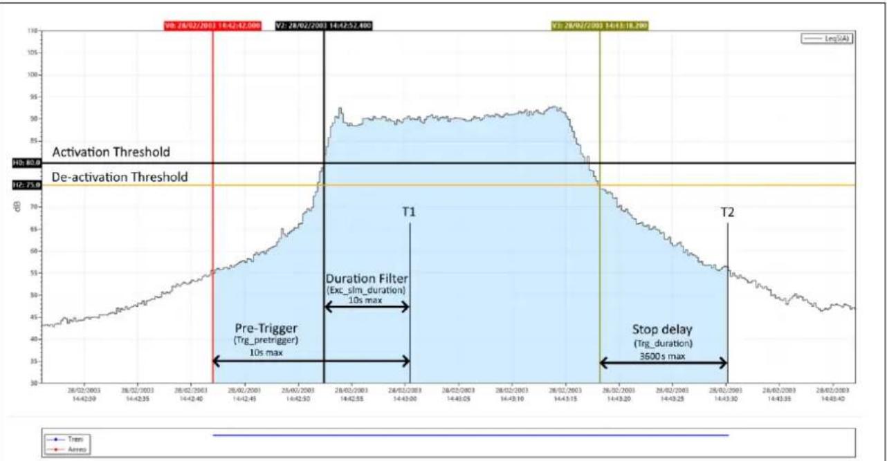
line
| Time Period | Value | | ----------------- | --------- | | 28/02/2003 | 80.0 | | 14/42:52.490 | 80.0 | | 28/02/2003 | 80.0 | | 14/43:18.290 | 80.0 | | 28/02/2003 | 80.0 | | 14/43:36.00 | 80.0 | | 28/02/2003 | 80.0 | | 14/43:35 | 75.0 | | 28/02/2003 | 75.0 | | 14/43:33 | 75.0 | | 28/02/2003 | 75.0 | | 14/43:31 | 75.0 | | 28/02/2003 | 75.0 | | 14/43:29 | 75.0 | | 28/02/2003 | 75.0 | | 14/43:27 | 75.0 | | 28/02/2003 | 75.0 | | 14/43:25 | 75.0 | | 28/02/2003 | 75.0 | | 14/43:23 | 75.0 | | 28/02/2003 | 75.0 | | 14/43:21 | 75.0 | | 28/02/2003 | 75.0 | | 14/43:19 | 75.0 | | 28/02/2003 | 75.0 | | 14/43:17 | 75.0 | | 28/02/2003 | 75.0 | | 14/43:15 | 75.0 | | 28/02/2003 | 75.0 | | 14/43:13 | 75.0 | | 28/02/2003 | 75.0 | | 14/43:11 | 75.0 | | 28/02/2003 | 75.0 | | 14/43:19 | 75.0 | | 28/02/2003 | 75.0 | | 14/43:17 | 75.0 | | 28/02/21 | 75.0 | | 14/43:15 | 75.0 | | 28/02/21 | 75.0 | | 14/43:13 | 75.0 | | 28/02/21 | 75.0 | | 14/43:11 | 75.0 | | 28/02/21 | 75.0 | | 14/43:19 | 75.0 | | 28/02/21 | 75.0 | | 14/43:17 | 75.0 | | 28/02/21 | 75.0 | | 14/43:15 | 75.0 | | 28/02/21 | 75.0 | | 14/43:13 | 75,0 | | 28/02/21 | 75,0 | | T1 | Peak | | Duration Filter | Excl_sim_duration; 10s max | | Stop delay | Excl_sim_duration; 3600s max | | Pre-Trigger | Trg_pretrigger; 10s maxFig. 15 - Event identification by trigger function
To prevent even short pulses from being identified as sound events, a minimum activation duration (duration filter) of up to a maximum of 10s can be set. If the activation threshold is exceeded for less than the set time, the event is not taken into account. A stop delay can also be set: when the deactivation threshold is reached, the event is delayed for the set time up to a maximum of 3600s. In the example above, as the trigger conditions persist beyond the set minimum duration, i.e. at least until time T1, the action provided by the trigger function begins; this includes the seconds before the trigger threshold is exceeded (pre-trigger). The pre-trigger interval can be set via the parameter Trg_pretrigger. The trigger action is terminated at time T2, with a delay equal to the stop delay starting from the instant identified by cursor V3 corresponding to the crossing of the stop threshold. The trigger to identify an event, can also be activated by means of an electrical signal connected to the Trigger I/O input (20.5 Trigger I/O Input) or by pressing a button from the interface (see 10.5 Customizing markers). In both cases the minimum duration parameter has no effect, and the event starts as soon as the trigger is detected.
20.1 Exceedances settings
One or more of the acoustic parameters set and displayed in the SLM screen can be used to trigger. The parameters selected and activated to generate the trigger will be available as input for the trigger. In the case of several activated parameters, it will be possible to combine them (OR/END logic) together to generate advanced multi-parameter triggers.
| Tap on one of the parameters on the SLM screen to access the panel relating to the parameter on which a trigger is to be activated; from there, use the three dots: to set the relevant parameters such as the exceedance thresholds that trigger on and off, the mode and duration. | P1: √ XLAFp ... Help:LXFp: sound pressure level FastX = A, C + B or Z (selectable) |
20.1.1 Exceedance of SLM parameters
Reaching the set conditions for exceedances can be used to generate a trigger. The trigger, once activated, can generate a specific action (e.g. the automatic recording of an audio signal).
| Set the exceedance activation MODE (see “20.1.2 Exceedance SLM mode (Exc_slm_mode)”)Set activation threshold value (MAX)Set deactivation threshold value (MIN)Set minimum exceedance duration time (duration filter) for trigger activation (see “20.1.4 SLM exceedance duration filter (Exc_slm_duration)”) | MODE: POSMAX: 100.0MIN: 90.0DURATION: 0 |
20.1.2 Exceedance SLM mode (Exc\_slm\_mode)
Through the MODE parameter, it is possible to trigger on SLM acoustic parameters exceedances according to 4 different modes described below. Four values are available: POS, NEG, IN, OUT
POS
The exceedance occurs (trigger ON) when the sound level goes from a lower to a higher value than the Max value (threshold Max) set as the trigger activation threshold and is deactivated (trigger OFF) when the sound level goes from a higher to a lower value than the Min value (threshold Min) set as the trigger deactivation threshold.
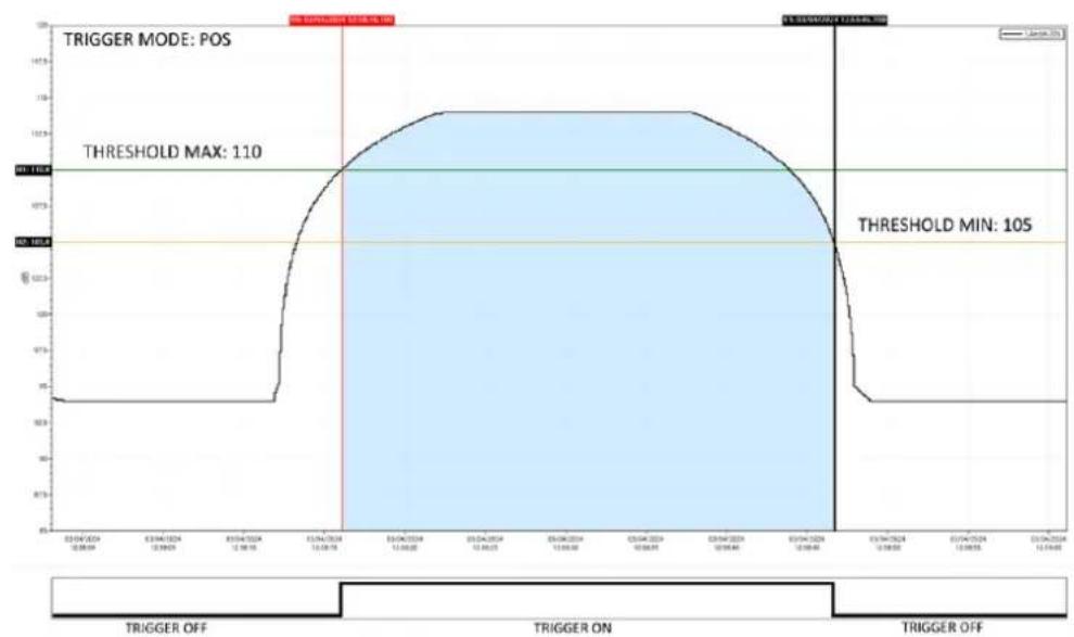
line
| Time | Value | | ---------- | ----- | | 03/04/2024 | 95 | | 03/04/2024 | 110 | | 03/06/2024 | 110 | | 03/06/2024 | 105 | | 03/06/2024 | 95 |Fig. 16 - Trigger mode POS
NEG
The exceedance occurs (trigger ON) when the sound level goes from a higher to a lower value than the Min (threshold Min) value set as the trigger activation threshold and is deactivated (trigger OFF) when the sound level goes from a lower to a higher value than the Max value (threshold Max) set as the trigger deactivation threshold.
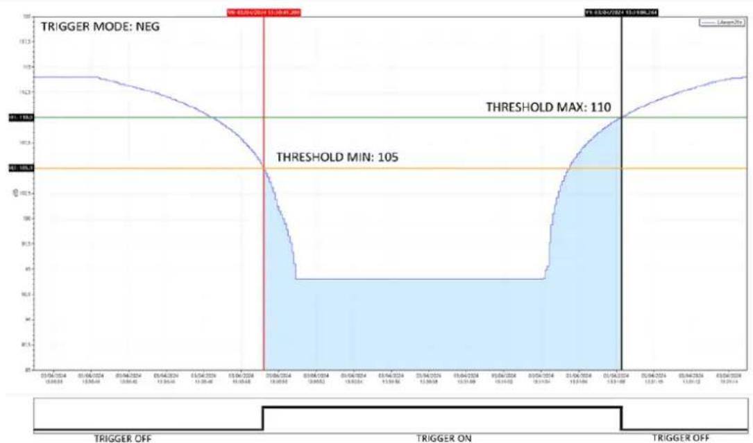
line
| Date | Value | | ---------- | ----- | | 03/04/2024 | 110 | | 09/04/2024 | 105 |Fig. 17 - Trigger mode NEG
IN
The exceedance is activated when the sound level is between the set Max (threshold Max) and Min (threshold Min) value.
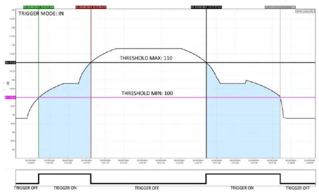
line
| Date | Voltage | | ---------- | ------- | | 20/01/2014 | 90 | | 20/01/2014 | 100 | | 20/01/2014 | 110 | | 20/01/2014 | 100 | | 20/01/2014 | 90 |Fig. 18 - Trigger mode IN
OUT
The exceedance is activated when the sound level is not between the set Max (threshold Max) and Min (threshold Min) value.
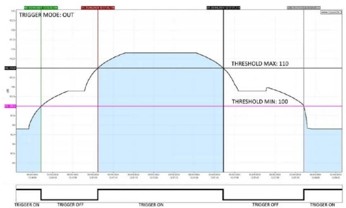
line
| Date | Value | | ---------- | ----- | | 06/04/2014 | 110 | | 31/04/2014 | 100 |Fig. 19 - Trigger mode OUT
20.1.3 Exceedance SLM thresholds (Exc\_slm\_threshold)
User input of two level values Max and Min is required: start threshold or stop threshold depending on the selected mode (POS, NEG, IN, OUT).
Trigger start threshold: the threshold for triggering on the level reached by the selected parameter.
Trigger stop threshold: a separate deactivation threshold for triggering on the level reached by the selected parameter.
20.1.4 SLM exceedance duration filter (Exc\_slm\_duration)
A duration filter is available to eliminate false triggers. An event is only triggered if the over level condition persists for a number of seconds at least equal to this parameter (parameter value 0-10s).
20.1.5 Enabling SLM exceedances (Exc\_slm\_enable)
Enables or disables the use of exceedance on SLM (Trigger Input) parameters
| Red bell = ONGrey bell = OFF | Exceedance on/off | Settings |
20.2 Setup trigger
(EDIT APP > TRIGGER > SETUP or SETTINGS > TRIGGER > SETUP)
General trigger parameters are available for setting on SETUP menu
20.2.1 Pre-trigger
This is the time interval before the trigger occurrence. The event generated by the trigger activation will also include the configurable time interval before the trigger activation. The function makes it possible to also detect or include in the calculations the level increase phase of a sound event or particularly fast events whose phase before the trigger is triggered. (parameter value 0-10s)
20.2.2 Post-trigger duration
After the deactivation threshold is reached, the trigger remains active for a user-settable time. It is possible in this way, for example, to encode the 'tail' of a sound event (parameter value 0-3600s).
20.3 INPUT
(EDIT APP > TRIGGER > INPUT)
The trigger input can be chosen from one or more of the parameters set in the SLM screen and activated for the trigger. The parameters selectable as trigger inputs are only those for which the Exceedance on/off (bell) function has been activated in the setting panel relating to the selected SLM parameter. Parameters selected as trigger inputs can be set to each other in OR or END logic.
20.3.1 SLM
The screen shows 12 parameters (among which there can also be coupled parameters of the type L1 minus L2), 6 related to Par1 and 6 related to Par 2. Only the parameters available for the trigger (Exceedance on) will be active; those not available (Exceedance off) will be visible but deactivated and in grey colour; for the latter, the selection on/off checkbox cannot be activated.
The on/off checkbox can be used to activate or deactivate the parameter for its use as a trigger during measurement.
If the logic between Par1 and Par2 is set to AND, it is possible to select one of the activated SLM parameters in Par2 for the trigger (Exceedance on). Activating the AND logic will only trigger if both Par1 and Par2 reach the values set in the exceedance panel.
20.3.2 MRK
Allows the marker name to be changed and activated by check box.
20.3.3 MIX
Trigger IN (ON/OFF): enables external trigger on Trigger I/O input
20.4 Setting exceedances of a spectrum in octave or third octave bands
The exceedance monitoring function on the octave or third-octave band spectrum allows min and max thresholds to be set for each band (spectrum exceedance mask). The exceeding of one or more bands generates a trigger.
Setting thresholds for each frequency band:
From graphic interface in EDIT APP/TRIGGER/SPECTRUM
- Select the band using the vertical cursor
- Modify the thresholds of the Min and Max fields
- click SAVE (the file exceedances_xOCT.json is modified and stored - see below).
- Click LOAD to load and display the mask (in orange color) with the thresholds set.
from PC
- By directly editing with text editor the file at path XPT80x/sn./System/exceedances_xOCT.json having the following format:
| Octave | Third Octave | ||
| "Octave":{ | "Third Octave":{ | ||
| "8" | [140.0,80.0] | "6.3" | [140.0,80.0] |
| "16" | [140.0,80.0] | "8" | [140.0,80.0] |
| "31.5" | [140.0,80.0] | "10" | [140.0,80.0] |
| "63" | [100.0,80.0] | "12.5" | [140.0,80.0] |
| "125" | [100.0,80.0] | "16" | [140.0,80.0] |
| "250" | [100.0,80.0] | "20" | [140.0,80.0] |
| "500" | [100.0,80.0] | "25" | [140.0,80.0] |
| "1k" | [100.0,80.0] | "31.5" | [140.0,80.0] |
| "2k" | [100.0,80.0] | "40" | [100.0,80.0] |
| "4k" | [100.0,80.0] | "50" | [100.0,80.0] |
| "8k" | [100.0,80.0] | "63" | [100.0,80.0] |
| "16k" | [100.0,80.0] | "80" | [100.0,80.0] |
| "100" | [100.0,80.0] | ||
| "125" | [100.0,80.0] | ||
| "160" | [100.0,80.0] | ||
| "200" | [100.0,80.0] | ||
| "250" | [100.0,80.0] | ||
| "315" | [100.0,80.0] | ||
| "400" | [100.0,80.0] | ||
| "500" | [100.0,80.0] | ||
| "630" | [100.0,80.0] | ||
| "800" | [100.0,80.0] | ||
| "1k" | [100.0,80.0] | ||
| "1.25k" | [100.0,80.0] | ||
| "1.6k" | [100.0,80.0] | ||
| "2k" | [100.0,80.0] | ||
| "2.5k" | [100.0,80.0] | ||
| "3.15k" | [100.0,80.0] | ||
| "4k" | [100.0,80.0] | ||
| "5k" | [100.0,80.0] | ||
| "6.3k" | [100.0,80.0] | ||
| "8k" | [100.0,80.0] | ||
| "10k" | [100.0,80.0] | ||
| "12.5k" | [100.0,80.0] | ||
| "16k" | [100.0,80.0] | ||
| "20k" | [100.0,80.0] | ||
20.4.1 Enabling Spectrum exceedances
From graphic interface access the spectrum view (or EDIT APP/SEL.VIEW/SPECTRUM)
- Tap the bell to access the setting
• BANDS: select SINGLE or ALL
SINGLE (reaching the conditions of at least one band generates the surplus)
ALL (reaching of exceedance conditions must be true for all bands)
- Select required MODE (see 20.1.2 Exceedance SLM mode (Exc_slm_mode) on page 113)
- Activate the exceedance switching the cursor to ON
With exceedance activated, the bell icon in the spectrum view changes from gray to white (or black depending on the display colour mode).
When the set conditions for exceedances are reached, the bell turns red and a trigger is generated.
20.5 Trigger I/O Input
The input can be used to receive (Trigger IN) or send (Trigger OUT) electrical signals.
The input settings can be modified from SETTINGS/TRIGGER/TRGIO
20.5.1 TRGOUT polarity
Sets the polarity of the output trigger signal
POS: the polarity of the output signal is positive
NEG: the polarity of the output signal is negative
20.5.2 TRIGIN polarity
Sets the polarity of the input trigger signal
POS
IN
20.5.3 TRGOUT Mode
Sets the mode of the output trigger signal
OFF
MEAS
TRG
21 Appendix D - File system information
21.1 XPT80X\_SLM\_Config
The file contains information about the specific device, such as the microphone serial number. It is strongly recommended that this file is backed up; if the device is formatted, restoring the file to the file system will allow information about the device to be recovered.
The file can be found in the following path:
Memory unit:\XPT800_2404A00000Configuration\SLM\000000000001.conf
"XPT80X_SLM_Config":
"preamplifier_model": "MP800"
"preamplifier_serial": "000000000001"
"microphone_model": "MC800"
"microphone_serial": "000001"
"microphone_polarization": "0V"
"sensitivity": "-26.0dB"
"CIC_option": "YES"
"HEATER_option": "YES"
22 Declaration of Conformity

senseca

DICHIARAZIONE DI CONFORMITÀ UE EU DECLARATION OF CONFORMITY
Senseca Italy S.r.l. | Via Marconi, 5 | 35030 Selvazzano Dentro (PD) | ITALY
Documento Nr. / Mese.Anno:
5214 / 05.2024
Document-No. / Month.Year:
We declare herewith under our sole responsibility that the following products are in compliance with the protection requirements defined in the European Council directives:
Codice prodotto:
XPT800
Product identifier:
Product description:
Sound level meter
The products conform to following European Directives:
| Direttive / Directives | |
| 2014/53/EU | Direttiva apparecchiature radio / Radio Equipments Directive (RED) |
| 2011/65/EU - 2015/863/EU | RoHS |
Applied harmonized standards or mentioned technical specifications:
| Norme armonizzate / harmonized standards | |
| EN 61326-1:2021 | EMC - Prescrizioni generali / General requirements |
| EN 61326-2-3:2021 | EMC - Prescrizioni particolari / Particular requirements |
| EN 62479:2010 | Esposizione umana a campi elettromagnetici / Human exposure to EMF |
| ETSI EN 301 489-1 V2.1.1 | EMC - Dispositivi radio / Radio equipments |
| ETSI EN 301 489-17 V3.1.1 | EMC - Dispositivi RF a banda larga / RF broadband devices |
| ETSI EN 300 328 V2.1.1 | Dispositivi RF a banda larga / RF wideband devices |
| EN 61010-1:2010/A1/AC:2019 | Requisiti di sicurezza elettrica / Electrical safety requirements |
| EN IEC 63000:2018 | RoHS |
The manufacturer is responsible for the declaration released by:
Gianluca Maestroni
VP Environmental BU
Selvazzano Dentro, 14/05/2024

This declaration certifies the agreement with the harmonization legislation mentioned, contained however no warranty of characteristics.
WARRANTY
The manufacturer is required to respond to the "factory warranty" only in those cases provided by Legislative Decree 6 September 2005 - n. 206. Each instrument is sold after rigorous inspections; if any manufacturing defect is found, it is necessary to contact the distributor where the instrument was purchased from. During the warranty period (24 months from the date of invoice) any manufacturing defects found will be repaired free of charge. Misuse, wear, neglect, lack or inefficient maintenance as well as theft and damage during transport are excluded. Warranty does not apply if changes, tampering or unauthorized repairs are made on the product. Solutions, probes, electrodes and microphones are not guaranteed as the improper use, even for a few minutes, may cause irreparable damages. The manufacturer repairs the products that show defects of construction in accordance with the terms and conditions of warranty included in the manual of the product. For any dispute, the competent court is the Court of Padua. The Italian law and the "Convention on Contracts for the International Sales of Goods" apply.
TECHNICAL INFORMATION
The quality level of our instruments is the result of the continuous product development. This may lead to differences between the information reported in the manual and the instrument you have purchased. We reserve the right to change technical specifications and dimensions to fit the product requirements without prior notice.
DISPOSAL INFORMATION

Electrical and electronic equipment marked with specific symbol in compliance with 2012/19/EU Directive must be disposed of separately from household waste. European users can hand them over to the dealer or to the manufacturer when purchasing a new electrical and electronic equipment, or to a WEEE collection point designated by local authorities. Illegal disposal is punished by law.
Disposing of electrical and electronic equipment separately from normal waste helps to preserve natural resources and allows materials to be recycled in an environmentally friendly way without risks to human health.

senseca.com

Senseca Italy S.r.l.
Via Marconi, 5
35030 Selvazzano Dentro (PD)
ITALY
info@senseca.com

- Contents
- Information....6
- Compliance and directives 9
- Identification....11
- Description of the instrument 12
- Display 20
- Pre-use checks and operations 27
- Assembling and disassembling components.... 32
- Battery power supply 35
- External power supply 38
- Switching on and off 39
- Settings and Adjustments....41
- Viewing modes....46
- Getting started: Main Functions....52
- Advanced functions....66
- Managing measurement data files....80
- Information
- General information
- Properties of information
- Version info
- Use of the manual
- Symbols in the manual
- Info
- Notice!
- Warning!
- Forbidden!
- Observe the instructions!
- Safety information
- Compliance and directives
- Acoustical Directives
- Sound Level Meter:
- IEEE 802.11 (Wi-Fi) certifications:
- FCC and IC notices
- Identification
- Product identification
- Part numbers of main components and accessories
- Explanation of product code
- Description of the instrument
- Basic features
- Possible applications
- Main features
- Performance characteristics
- Instrument hardware overview
- Description of main components
- Microphone
- Preamplifier
- Heater
- Automatic detection
- Instrument
- Outdoor microphone unit (optional)
- Display
- Icon menu
- Status Bar
- Activation keys
- Control Bar
- Context menu
- Navigation and selection
- Keyboard
- ENTER function
- Entering text and numbers
- Pre-use checks and operations
- Unpacking and inspection
- Standard configuration
- Options and accessories
- Hardware accessories
- Hardware options
- Firmware options
- Software options
- Assembling and disassembling components
- Microphone and preamplifier
- To connect the microphone and preamplifier.:
- To disconnect the microphone and preamplifier.:
- Windscreen
- Outdoor microphone unit
- Connect the outdoor microphone unit to the sound level meter
- Mounting on a tripod
- Battery power supply
- Battery power use
- Battery charge indicator
- Charging the battery
- Battery insertion and replacement
- Battery replacement
- Inserting the battery
- External power supply
- Using power supply via USB port
- Switching on and off
- Switching on
- Display auto-off function
- Switching off
- Settings and Adjustments
- Set current date and time
- Using NTP server to synchronize date and time
- Setting the language
- Display adjustments
- Adjusting the brightness
- Setting the display auto power off
- Selecting the display theme
- Turning the TOUCH display on and off
- Viewing modes
- SLM (Sound Level Meter)
- TABLE
- FREQUENCY SPECTRUM (Histogram)
- TIME HISTORY
- SLM mode
- TABLE mode
- INSTANTANEOUS
- AVERAGES
- PERCENTILE AVERAGES
- MAXIMUMS - MINIMUMS
- SPECTRUM
- SLM EXCEEDANSES
- MARKERS
- Octave and Third Octave display (histogram)
- Time History display
- Getting started: Main Functions
- Calibration
- Setting the duration of a measurement
- Select acoustic parameters to be displayed
- Set acoustic parameters to be stored
- Subtraction of two acoustic parameters
- Load a custom configuration
- Set alarms on exceedances
- Starting and stopping a measurement
- Starting and stopping a measurement with datalogging
- Recording an audio manually
- Manually add markers to the measurement
- Advanced functions
- Setting the calibration parameters
- Setup
- Acoustic field
- Correction applied for the use of WS90 or WSO windscreens (Shield correction)
- Calibrator emission level (Level)
- Correction applied after calibration (Correction)
- Calibration mode
- Calibrations History
- Setting triggers
- Setting audio recording parameters
- Audio recording mode
- Continuous audio recording
- Event-based audio recording
- Audio recording resolution
- Audio recording sampling frequency
- Setting a duration limit to audio recordings
- Custom measurement setups
- "Current" Configuration
- Load, Edit, Save as, Delete functions
- "Lock" and "Auto-Load" attributes
- Customizing markers
- Continuous measurements datalogging
- Recording Configuration
- History interval
- Measure name (Log\_name)
- Log file max size (Log\_file\_size)
- Log synchronization (Log\_sync)
- Sync files (Log\_sync\_type)
- Start of Reports (Report\_sync)
- Sync backlog (Sync\_files)
- Continuous datalogging of Time History group
- Continuous datalogging of Reports group
- Datalogging of Events group
- Recording Globals group
- PLAYBACK and GENERATOR
- PLAYBACK management
- GENERATOR management
- Available parameters:
- Activating the preamplifier heater
- Monitor
- Managing measurement data files
- Setting the data file storage unit
- Saving data to an external USB-C drive
- Information on data file naming
- Parameter Log\_sequence = OFF
- Example:
- Parameter Log\_sequence = ON\*
- Using the data file Archive
- Visualization of data files
- Manual cloud synchronisation of data files
- Entering a voice note to the measurement
- Renaming and deleting a data file
- Saving of data files
- Saving on PC
- Data storage on Cloud
- From DEVICE
- From PC
- Automatic cloud synchronisation of data files via Push option
- Network and connections
- Network Settings
- Connecting to a WiFi network
- Access Points panel
- Access points setup panel
- Connecting to an Ethernet port
- Connecting through GSM network \*
- Connecting to a PC with USB interface
- Firmware update and options
- Firmware version
- Firmware update
- Wi-Fi firmware update
- Instrument recovery via recovery firmware
- Enabling or disabling options
- Maintenance Operations
- Cleaning the Instrument
- Microphone cleaning (microphone diaphragm)
- Accredited periodical calibration
- Troubleshooting Guide
- Formatting eMMC memory (FORMAT)
- Formatting from device
- Formatting from pc
- Restoring Parameters to Default Settings (Reset)
- Malfunctions, causes and possible solutions
- ◆ Calibration procedure fails:
- Possible solutions:
- ❖ The sound levels measured by the sound level meter appear to be incorrect:
- ❖ The sound level meter switches off immediately after the power-up presentation screen:
- ❖ The sound level meter does not communicate with the PC:
- ✿ Continuous logging cannot be activated. The instrument starts measurements without data recording:
- ❖ Manual audio recording does not work:
- ❖ Automatic audio recording does not start:
- Long-term storage
- Spare parts
- Appendix A - Technical Specifications
- Appendix B - Parameters
- Measure Parameters
- Composition of Acoustic parameters Labels
- Description of acoustic parameter labels
- Acoustic parameter label variables
- Acoustic Parameter labelling example
- Classes of measurement parameters available for visualisation
- Classes of measurement parameters available for storage
- Types of parameters available for screens (views)
- Types of parameters available for storage
- Setup Parameters
- Appendix C - Trigger
- Exceedances settings
- Exceedance of SLM parameters
- Exceedance SLM mode (Exc\_slm\_mode)
- POS
- NEG
- IN
- OUT
- Exceedance SLM thresholds (Exc\_slm\_threshold)
- SLM exceedance duration filter (Exc\_slm\_duration)
- Enabling SLM exceedances (Exc\_slm\_enable)
- Setup trigger
- Pre-trigger
- Post-trigger duration
- INPUT
- SLM
- MRK
- MIX
- Setting exceedances of a spectrum in octave or third octave bands
- From graphic interface in EDIT APP/TRIGGER/SPECTRUM
- Enabling Spectrum exceedances
- Trigger I/O Input
- TRGOUT polarity
- TRIGIN polarity
- TRGOUT Mode
- Appendix D - File system information
- XPT80X\_SLM\_Config
- Declaration of Conformity
- senseca
- DICHIARAZIONE DI CONFORMITÀ UE EU DECLARATION OF CONFORMITY
- WARRANTY
- TECHNICAL INFORMATION
- DISPOSAL INFORMATION
Brand : Senseca
Model : XPT800
Category : Uncategorized