
Talos E3 CG - Uncategorized Gamdias - Free user manual and instructions
Find the device manual for free Talos E3 CG Gamdias in PDF.


| Product Type | Mid-Tower PC Case |
| Model | Talos E3 CG |
| Brand | Gamdias |
| Motherboard Compatibility | ATX, Micro-ATX, Mini-ITX |
| Drive Bays | 2 x 3.5" HDD (internal), 2 x 2.5" SSD (internal) |
| Expansion Slots | 7 |
| Fan Support (Front) | 3 x 120mm or 2 x 140mm |
| Fan Support (Top) | 2 x 120mm or 2 x 140mm |
| Fan Support (Rear) | 1 x 120mm |
| Radiator Support | Front: 240/280mm; Top: 240mm; Rear: 120mm |
| Power Supply Mounting | Bottom, ATX PS/2 |
| Maximum GPU Length | 330mm (approx.) |
| Maximum CPU Cooler Height | 160mm (approx.) |
| Dimensions (W x H x D) | 210 x 480 x 420 mm (approx.) |
| Weight | 6.5 kg (approx.) |
| Material | Steel chassis, tempered glass side panel |
| I/O Ports | USB 3.0 x 2, USB 2.0 x 2, HD Audio, Mic |
| Dust Filters | Bottom PSU filter, front mesh filter |
| Cleaning | Use a soft cloth; clean dust filters monthly |
| Warranty | 1 year (check manufacturer) |
Frequently Asked Questions - Talos E3 CG Gamdias
User questions about Talos E3 CG Gamdias
0 question about this device. Answer the ones you know or ask your own.
Ask a new question about this device
Download the instructions for your Uncategorized in PDF format for free! Find your manual Talos E3 CG - Gamdias and take your electronic device back in hand. On this page are published all the documents necessary for the use of your device. Talos E3 CG by Gamdias.
USER MANUAL Talos E3 CG Gamdias
GAMING ART IN MOTION
TALOS IE3
MID-Tower PC Case
natural_image
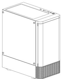
Technical line drawing of a rectangular electronic device with a shaded base (no text or symbols)▼ Case Layout and Parts Identification Fan Cable

- Front Panel
- Top Magnetic Dust Filter
- ID Port Module
- Top Radiator (Fan) Mounting Holes
- Right Side Pane
B. Left Side Tempered Glass - PCIe Slots
B. Power Supply Unit Mounting Hole - Power Shroud
- Power Shroud Fan Mounting Hole
- Rear Fan
- Front Fans
- Motherboard Placement
- Motherboard Mounting Holes
- HDD/ SSD Cage
- Chassis Pedestals
▼
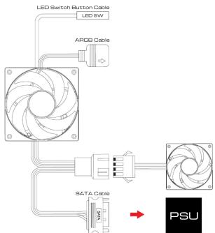
flowchart
graph TD
    A["LED Switch Button Cable"] --> B["ARDB Cable"]
    B --> C["SATA Cable"]
    C --> D["PSU"]
    E["LED SW"] --> A
    F["Power Supply"] --> C
▼ Safety Information Case Layout and Parts Identification
- General Safety Warnings
Always ensure the computer case is placed on a stable, flat surface to prevent it from tipping over. Keep the case simply from water moisture, or high humidity requirements to avoid electrical loads.
Keep the cause away from water, moisture, or high humidity environments to avoid electrical hazards. Do not block or obstruct the ventilation openings to ensure proper airlines and prevent overheating.
-
Electrical Safety
-
Electrical Safety Disconnect the power supply before installing or modifying any internal components
Avoid touching internal components directly; always ground yourself to prevent static discharge, which can
damage sensitive components.
Use only complication fraying or damage.
- Handling Precautions
Handle the computer case with cane during transportation to prevent physical damage.
Use appropriate tools when assembling or disassembling components inside the case to avoid injury.
Do not force components into
- Fire Hazard Warnings
Ensure all components are properly ventilated and not overheating, as this can be a potential fire hazard.
Avoid overloading electrical circuits connected to the computer case to prevent overheating and potential
fine risks. Koon flammable materials were from the same step news.
,
- Child Safety
Keep the computer case and its components out of reach of children.
Do not allow children to play with or operate the computer case, especially when it is powered on.
- Cleaning and Maintenance
Unplug the computer case from the power source before cleaning.
Use a dry, soft cloth for cleaning the exterior of the case. Do not use liquid cleaners or serocells.
Periodically check and clean the ventilation openings to ensure
- Installation Safety
Ensure that all components are installed correctly and securely before powering on the system.
Double-check connections and screws to prevent potential hazards during operation.
Follow the manufacturer's guidelines for component installation and ensure compatibility with the case
[Non-Text]
- Disposal Instructions
Dispose of the computer case and its components according to local electronic waste regulations.
▼
-
Gaming Case : TALOS ES 03
-
Chassis Protection : EPS Protection Foam
-
Chassis Dust Cows
-
Projected Items: CAMPOS NETI 6 Items = 7
-
Price Target Fund: GANDBAS NETCUTA
A Motherboard/ SSO screws
The Ground Truth image displays a single, solid horizontal line. According to Rule 2 (UNDERSCORE & LINE RULES), if the GT contains lines used for stylistic emphasis or as background elements (like ruled paper), the OCR result must ignore them. The provided OCR content is "____", which consists of four underscores. This is incorrect because underscores are not equivalent to a solid line and are not permitted under the “Stylistic/Background Lines (Ignore)” rule. The OCR has hallucinated underscores where none should exist in the GT, violating the “Stylistic/Background Lines (Ignore)” rule. Therefore, the OCR result is inconsistent with the Ground Truth.
B. Motherboard additional standoffs ____
- 项目(以下简称“项目”)
C.PBU/GPU/PGs screws
□ HDD capar screens
-
Average Rev. Rate Tax
-
Azerbaijan's Bank : Clabri Tama
▼ Case Layout and Parts Identification
- Case Type: MID Tower
9 Motherboard Support: ATX Micro-ATX Mini-TX
(2) 1403480076589
-
Expansion Slots: 7
-
Material: BPCC, ABS, Tempered Glass
-
Product Dimension : 383 x 210 x 447mm(14.3 x 8.3 x 17.8 inch)
© Cheasia Dimension: 320 x 240 x 470mm(13 x 8.5 x 35.9 inch)
-
用 H2O 和 H3O 的溶液,用 H2O 和 H3O 的溶液,用 H2O 和 H3O 的溶液,用 H2O 和 H3O 的溶液,用于
-
Radiator Support : Top: 240 mm · Front: 260 mm, 280 mm · Rear: 320 mm
-
Fan Support: Top: 2 x 120mm · Front: 2 x 120 mm, 2 x 140mm · Rear: 1 x 120mm
-
Motherboard Sync : 5V 3-Pin Addressable Header
3D Drive Revs: R x 95% on 1 x 85%+1 x 95% (FD Caps): R x 85%
-
Gluennan, 2014: Open lead-in fligation, 2015: USA longs fligation, 2016:
-
DataArea: CPU 8564P H align PSU Length limitation: 250mm
▼ Motherboard Installation Power Supply Unit (PSU) Installation
The following table is provided in the image.
Place the standards in the appropriate positions for your motherboard size.
7.3.1.2.3.4.5.6.7.8.9.10.11.12.13.14.15.16.17.18.19.20.21.22.23.24.25.26.27.28.29.30.31.32.33.34.35.36.37.38.39.40.41.42.43.44.45.46.47.48.49.50.51.52.53.54.55.56.57.58.59.60.61.62.63.64.65.66.67.68.69.70.71.72.73.74.75.76.77.78.79.80.81.82.83.84.85.86.87.88.89.90.91.92.93.94.95.96.97.98.99.100
Aigh the motherboard with the standards and secure it with screws.

natural_image
Interior view of a server rack with an open rear panel and a red arrow pointing to a component (no text or symbols visible)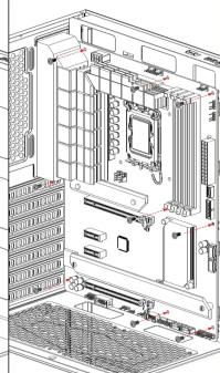
natural_image
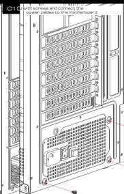
Technical line drawing of a computer tower internal structure (no text or symbols)
▼ Safety Information Case Layout and Parts Identification GPU Installation ▼PU Installation
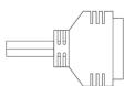
USB 3.0

[Non-Text]
Power Switch


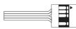
HD Audio


LED Switch Button Cable


ARGB Cable
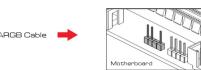
LED Switch Button
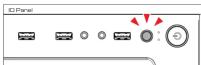
1. Lightly touch the LED button on the case to switch lighting effects.
9. Press and hold the LED button on the case to enter motherboard sync mode.
Q. In motherboard sync mode, lightly touch the button to exit motherboard sync mode.
m = 311


natural_image
Diagram of a computer tower interior showing internal components and red arrows indicating movement or force (no text or symbols present)Identify the POHE x16 slots on the motherboard, usually the largest slot, closest to the CPU.
- Align the graphics cards connector with the PCRE slot and gently press down for the card is firmly backed in the slot. Secure the card to the case with screws
▼

Attach the grouped cables to the case's cable management points. Ensure that the cables are not obstructing any airflow or components.
Use additional zip ties or Velcro straps to secure any loose or excess cables. You can also use cable management
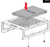
▼HDD Installation SSD Installation Fan and Cooling System Setup Case Layout and Parts Identification
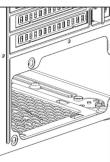
entify the appropriate drive bay in your case

natural_image
3D diagram of a device housing with labeled ports and a red arrow indicating direction (no text or symbols present)A-01


[Non-Text]

m = 311

natural_image
Technical diagram of a dual-panel assembly showing internal components and mounting points (no text or symbols)
▼
Troubleshooting and Maintenance
• Regularly clean the dust into air and radii to maintain airflow.
Figure 2.4.1.3.2017
- Our Family and Support Information
- Provides details on the warranty period and how an content support for experience
https://www.gamdias.com
Brand : Gamdias
Model : Talos E3 CG
Category : Uncategorized