
T30004R - Uncategorized INTERMATIC - Free user manual and instructions
Find the device manual for free T30004R INTERMATIC in PDF.


| Product Type | Indoor Timer |
| Brand | Intermatic |
| Model | T30004R |
| Category | Uncategorized (General Purpose Timer) |
| Voltage | 120 V AC |
| Amperage | 15 A |
| Wattage | 1800 W (max resistive) |
| Timer Type | Mechanical (analog) |
| Number of Programs | 1 On/Off cycle per day |
| Minimum On Time | 30 minutes |
| Maximum On Time | 23.5 hours |
| Operating Cycles | 24-hour repeating |
| Display Type | Analog dial with time indicators |
| Mounting Type | Wall or receptacle mounted |
| Dimensions (L x W x H) | 4.5 x 3.5 x 2 in (11.4 x 8.9 x 5.1 cm) |
| Weight | 0.5 lb (225 g) |
| Color | White / Ivory |
| Material | Plastic housing, metal contacts |
| Power Source | Hardwired or plug-in (varies by model variant) |
| Battery Backup | None (time settings lost on power outage) |
| Manual Override | Yes, lever or push button |
| Certifications | UL Listed, CSA Certified |
| Indoor/Outdoor | Indoor use only |
| Operating Temperature | 32°F to 104°F (0°C to 40°C) |
| Warranty | 1 year limited |
| Package Contents | Timer unit, mounting screws, manual |
Frequently Asked Questions - T30004R INTERMATIC
User questions about T30004R INTERMATIC
0 question about this device. Answer the ones you know or ask your own.
Ask a new question about this device
Download the instructions for your Uncategorized in PDF format for free! Find your manual T30004R - INTERMATIC and take your electronic device back in hand. On this page are published all the documents necessary for the use of your device. T30004R by INTERMATIC.
USER MANUAL T30004R INTERMATIC
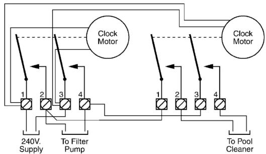
Filter and Cleaner Timer Inter-Connections
flowchart
graph TD
    A["Clock Motor"] --> B["240V Supply"]
    A --> C["To Filter Pump"]
    A --> D["To Pool Cleaner"]
    E["Clock Motor"] --> F["240V Supply"]
    E --> G["To Filter Pump"]
    E --> H["To Pool Cleaner"]
    I["1"] --> J["2"]
    K["2"] --> L["3"]
    M["4"] --> N["4"]
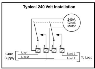
NOTES: 1. Grounding connections are not shown but must be provided. Refer to the National Electrical Code for details. 2. Diagrams above are only two of the many variations this Panel can accommodate.
WARRANTY
If within one (1) year from the date of installation, this product fails due to a defect in material or workmanship, Intermatic Incorporated will repair or replace it free of charge.
The warranty does not cover labor for removal or reinstallation and does not apply to: (a) damage caused by accident, abuse, mishandling, or dropping; (b) a unit which has been subject to unauthorized repair; (c) units not used in accordance with directions; (d) damages exceeding the cost of the product. Some states do not allow a limitation of damages so the foregoing warranty may not apply to you. This warranty gives you specific legal rights and you may also have other rights which vary from state to state.
This warranty service is available, if the defective product or its defective component is returned with proof of purchase and date of installation, either (a) to the dealer from whom the unit was purchased or (b) by shipping prepaid to the Intermatic Incorporated/After Sales Service, 7777 Winn Rd., Spring Grove, IL 60081-9698/815-675-7000 http://www.intermatic.com
Because of our commitment to continuing research and improvements, Intermatic Incorporated reserves the right to make changes, without notice, in the specifications and material contained herein and shall not be responsible for any damages, direct or consequential, owned by reliance on the material presented.
INTERMATIC INCORPORATED, SPRING GROVE, IL 60081-9698
http://www.intermatic.com
158TP10425

NTERMATIC®
T30000R SERIES
POOL/SPA EQUIPMENT CONTROLS
INSTALLATION
OPERATION &
SERVICE MANUAL
CONTROL PANEL WITH TIME SWITCH FOR INDOOR/OUTDOOR USE
Suitable for Pool Equipment Control and for Direct Connection of Underwater Lights ELECTRICAL RATINGS: See inside Enclosure Door
DANGER! TO AVOID RISK OF INJURY:
...do not permit children to operate the Control Unit or use the Pool/Spa unless they are closely supervised at all times. ...test GROUND FAULT protection regularly. If it fails to reset, DO NOT USE THE POOL or SPA!
Contact a qualified service technician. always disconnect electricity before servicing this control or the equipment connected to it.
READ, FOLLOW AND SAVE THIS INSTRUCTION MANUAL
GENERAL INFORMATION
Many of today's energy efficient pools and spas utilize the advantages of a single electrical panel, containing all the necessary controls for the safe, efficient and automatic operation of the pool/spa equipment. In addition, this Panel can also be used to control any outdoor equipment, sign or pump within its rated capacity.
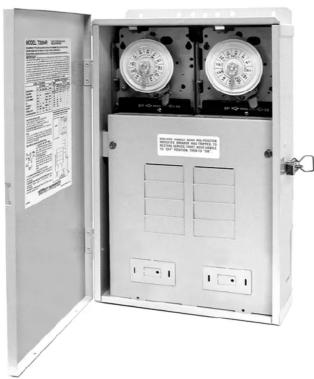
The all-weather enclosure contains none one or two heavy-duty, industrial grade Time Switches. Also, it has provisions to install switches or a GFCI receptacle on the side as well as the inside. The Time Switch can also accommodate an optional heater control (fireman) switch.
The Control is designed to operate any pump, within its rated capacity. However, if protection to prevent dry start is required by the pump manufacturer, it must be provided in addition to this Control. Contact pump manufacturer if not sure and/or for more details.
natural_image
Open electrical control cabinet with dual dials and buttons (no visible text or symbols)IMPORTANT SAFETY INSTRUCTIONS
When installing and operating this Product and other associated equipment, basic safety precautions should always be followed including the following:
-
Read and follow all instructions
-
This Control must be installed by a qualified electrician, according to National and Local Electrical Codes.
-
Install this control not less than 5 feet (3 meters in Canada) from inside edge of pool. USE COPPER CONDUCTORS ONLY.
-
Do not exceed the maximum ratings of individual components, wiring devices, and current carrying capacity of conductors.
-
For Control grounding, bonding, installing and the wiring of underwater lights, refer to Article 680 of the National Electrical
Code or Article 68 of the Canadian Electrical Code.
- The Control should not operate any equipment which would cause bodily injury or property damage should it be activated unexpectedly.
READ, FOLLOW AND SAVE THIS INSTRUCTION MANUAL
INSTALLATION
-
Remove the four #10 hex head screws from the back of the enclosure and attach mounting brackets to enclosure.
-
Select the proper location for the Control and hang enclosure on a flat vertical surface or other support, using hardware suitable for the purpose.
-
Prepare the necessary conduit runs, terminate them at both ends and pull in the conductors as specified by the installation layout.
-
Refer to Figure 1 below; note that this enclosure contains one or two Time Switch(es). To wire the panel, follow the wiring diagram located inside the enclosure door. Make sure that connections to time switch terminals are tight (25 lb.-in. minimum) and insulation clears the pressure plate - see illustration.
-
If required by the heater manufacturer, install fireman switch kit 156T4042A (not furnished) on Time Switch Plate and make the fireman switch connections. Use at least #18 AWG wiring with insulation rated 300 Volt or higher. Place heater ON/OFF switch on heater to ON (see Figure 2). Some heaters may require a special connecting harness, contact heater manufacturer for details.
-
For direct wiring of underwater lights, refer to 1999 NEC 680-21(b), 2002 NEC 680-24(b) or CEC 680-060, 062 and 066 for further details.
-
To install additional wiring devices inside the enclosure, first remove rectangular knock-out(s) in dead front. Next, remove hex head screws in back of enclosure and install stand-offs* in place of screws. Attach wiring device to stand-offs.
- Stand-offs are not furnished. Order 21T156A for a set of four (4) stand-offs and mounting hardware.
-
If external bonding is required, install a bonding lug at bottom of enclosure and bond installation according to code requirements.
-
Testing of the installation is optional and recommended only if pump is securely in place and will not be damaged by this test:
a. Turn the manual lever of the Time Switch to OFF.
b. Turn ON power at breaker panel.
c. Move the manual lever of Time Switch to the right (ON). Pump should start and run on full speed. In case of unsatisfactory results, turn OFF power, check your wiring, refer to Troubleshooting on Page 3
- Install front panel over wiring compartment. The control is now ready for programming, see OPERATION section on Page 3.
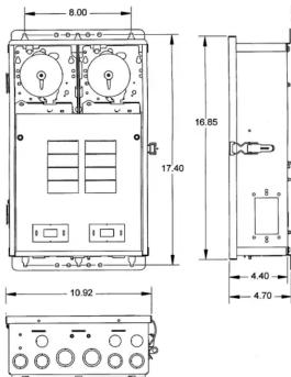
Figure 1
OPERATION
TO SET FILTER PUMP TIME SWITCH, follow instructions on the right. The length of the daily filtration/heating cycle depends on many variables such as size, shape, geographic location of the pool, water chemistry, type of pool equipment, usage and season of year. If not sure, contact your local pool service professional for advice.
THE FIREMAN SWITCH (Heater Protection Mechanism), if required, is factory set and shuts OFF the heater 20 minutes before the Time Switch turns OFF the filter pump. The Fireman Switch requires no setting or service.
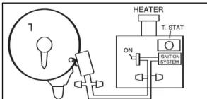
WARNING: Do not disconnect high limit or pressure switches. Figure 2
TIME SWITCH OPERATING INSTRUCTIONS
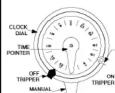
- TO SET "ON" AND "OFF" TIMES: Hold TRIPPERS against edge of CLOCK-DIAL, pointing to time (AM or PM) when ON and OFF operations are desired. Tighten tripper screws firmly.
2. TO SET TIME-OF-DAY:
Pull CLOCK-DIAL outward. Turn in either direction and align the exact time-of-day on the CLOCK-DIAL (the time now, when switch is being put into operation) to the pointer.
- TO OPERATE SWITCH MANUALLY: Move MANUAL LEVER below CLOCK-DIAL left or right as indicated by arrows. This will not affect the next operation.
• FOR MORE THAN ONE DAILY ON-OFF OPERATION: Place additional tripper pairs on CLOCK-DIAL (order 156T1978A).
- IN CASE OF POWER FAILURE: Reset CLOCK-DIAL to proper time of day. See step 2 above.
TROUBLESHOOTING
| SYMPTOM | CAUSE(S) | CORRECTIVE ACTION |
| 1. Time Switch will not keep time but dial is turning. | 1a.Frequent power outages1b.Wrong voltage/cycle1c.Loose clock motor connections | Reset dialChange clock motorCheck connections |
| 2. Time Switch Dial stops at ON or OFF tripper. | 2a.Loose tripper2b.Bent dial2c.Defective motor | Check/change tripperCheck/change mechanismChange clock motor |
| 3. Dial stops after switch turns OFF. | 3a.LINE leads are connected to LOAD terminals | Reverse LINE and LOAD connections |
| 4. Load is ON at all times - dial is turning. | 4a.Welded contacts4b.Two ON trippers and no OFF tripper on dial4c.Defective mechanism | Change mechanismChange tripperChange mechanism |
| 5. Dead clock motor. (Clock motor gears do not rotate). | 5a.Defective clock motor(open coil due to lightning or surge)5b.Loose clock motor connections5c.Wrong voltage | Change clock motorCheck connectionsChange clock motor |
- WARRANTY
- INTERMATIC INCORPORATED, SPRING GROVE, IL 60081-9698
- NTERMATIC®
- T30000R SERIES
- INSTALLATION
- OPERATION &
- SERVICE MANUAL
- CONTROL PANEL WITH TIME SWITCH FOR INDOOR/OUTDOOR USE
- DANGER! TO AVOID RISK OF INJURY:
- GENERAL INFORMATION
- IMPORTANT SAFETY INSTRUCTIONS
- READ, FOLLOW AND SAVE THIS INSTRUCTION MANUAL
- OPERATION
- TIME SWITCH OPERATING INSTRUCTIONS
- TO SET TIME-OF-DAY:
Brand : INTERMATIC
Model : T30004R
Category : Uncategorized