
MOD-DT4 - Uncategorized Panamax - Free user manual and instructions
Find the device manual for free MOD-DT4 Panamax in PDF.


| Product Type | Signal Line Protection Module (Secondary Protector) |
| Brand | Panamax |
| Model | MOD-DT4 |
| Compatibility | Compatible with Panamax AC base units (e.g., M8HT-PRO, PM8-EX, M4-EX, M8C-EX, M8-HT, PM8T-EX, M4T-EX, M8DBS-EX, PM8-HT, PM8C-EX, M8-EX, M8C-Pro, PM8DBS-EX, M8C-EX, M8HC-Pro) |
| Protection Type | Digital Station (DS) Set phone lines |
| Number of Lines Protected | Up to 4 lines (using RJ11 or RJ14 cords) |
| Input Connections | 110 punchdown block or RJ11/RJ14 jacks (LINE side) |
| Output Connections | 110 punchdown block or RJ11/RJ14 jacks (EQUIP side) |
| Mounting | Mounts to compatible AC base unit via included rectangular bracket |
| Grounding | Requires brass ground connector for bonding module ground to base unit ground |
| Safety | Do not install during lightning storms |
| Dimensions (approx.) | 4.5 x 2.5 x 1.5 inches |
| Weight (approx.) | 0.5 lbs |
| Color | Black |
| Warranty | Covered by Panamax Connected Equipment Protection Policy when installed correctly |
| Applications | Protects phone system from surges via backdoor pathways from station sets |
| Installation Notes | Base unit must be properly installed; all telephone input/output connections labeled LINE and EQUIP |
Frequently Asked Questions - MOD-DT4 Panamax
User questions about MOD-DT4 Panamax
0 question about this device. Answer the ones you know or ask your own.
Ask a new question about this device
Download the instructions for your Uncategorized in PDF format for free! Find your manual MOD-DT4 - Panamax and take your electronic device back in hand. On this page are published all the documents necessary for the use of your device. MOD-DT4 by Panamax.
USER MANUAL MOD-DT4 Panamax
INSTRUCTIONS FOR PANAMAX SIGNAL LINE PROTECTION MODULES - PREMIUM SERIES
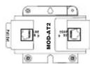
MOD-AT2
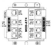
MOD-AT4

MOD-AT8110

MOD-DT4

MOD-UTP

MOD-CAT5
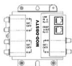
MOD-DBSTV

MOD-SPKP
These modules are approved accessories for use with compatible Panamax AC base units. Compatible base units include the following:
CURRENT PRODUCTS
AC Base Units
M8HT-PRO
PM8-EX
M4-EX
M8C-EX
M8-HT
PM8T-EX
M4T-EX
M8DBS-EX
PM8-HT
PM8C-EX
M8-EX
M8C-Pro
PM8DBS-EX
M8C-EX M8HC-Pro
DISCONTINUED PRODUCTS
AC Base Units
M4
M8
M8KSU
M4
M8T
M8COM
M4
M8C
M8KSU
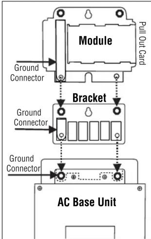
When properly installed, the base unit's Connected Equipment Protection Policy remains valid. All modules include a small rectangular bracket and mounting screws. This bracket replaces the small triangular wall-mount bracket that comes with the models listed in the CURRENT PRODUCTS above.
Installation Instructions
- Mount the rectangular bracket to the back of the AC base unit with the #8-32 x 5/16" machine screws.
Note: The brass ground connector must be used with the bracket in order to bond the module ground to the base unit's ground. - Mount the signal line module to the bracket (screws provided with the module).
- Optional – The assembled base unit and module(s) may be wall mounted if desired.
- Connect the wiring to the signal line module as shown in the appropriate following section.
All telephone input/output connections will be labeled with LINE and EQUIP.

LINE
IN ▶
It is very important to connect telephone signal lines properly.
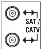
There are no designated input/output connections on coaxial protection modules. These are
bi-directional modules in both transmission frequency and voltage.
PANAMAX®
800-472-5555
www.panamax.com
An easy access
PULL OUT card is included on the back of each module for wiring diagrams and specifications.

Model: MOD-AT2 (Secondary Protector)
WIRING DIAGRAM AND SPECIFICATIONS
MOD-AT2

• 4 Wires (1 RJ-14) Protected
• 260 Volt Clamping
• Auto-resetting PTC's
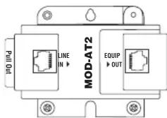
The MOD-AT2 module is designed to protect standard phone lines connected to computer modems, telephones, pay-per-view ports, etc. It will also protect DSL lines (ADSL, G.Lite) going into the DSL modem. The MOD-AT2 module will protect a single phone line using an RJ-11 (2 wire) cord or a dual phone line using an RJ-14 (4 wire) cord.
-
Connect the telephone line to the LINE jack on the module.
-
Use a modular cord to connect the EQUIP modular jack to the equipment to be protected.
Model: MOD-AT4 (Secondary Protector)
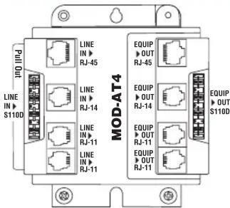
The MOD-AT4 module is designed to protect standard phone lines and DSL (ADSL, G.Lite) lines. Multiple input & output jacks provide complete installation flexibility. The following diagram shows how the jacks/wires are interconnected. Different cables/connections can be split or combined to accommodate a variety of installations. For example:
- Incoming lines can be punched-down on the 110 jack on the LINE side and four RJ11 (single-line) cords will connect from the EQUIP side to the equipment.

flowchart
graph TD
    A["Pin 1"] --> B["Pin 2"]
    C["Pin 3"] --> D["Pin 4"]
    E["Pin 5"] --> F["Pin 6"]
    G["Pin 7"] --> H["Pin 8"]
    I["Pin 9"] --> J["Pin 10"]
    K["Pin 11"] --> L["Pin 12"]
    M["Pin 13"] --> N["Pin 14"]
    O["Pin 15"] --> P["Pin 16"]
    Q["Pin 17"] --> R["Pin 18"]
    S["Pin 19"] --> T["Pin 20"]
    U["Pin 21"] --> V["Pin 22"]
    W["Pin 23"] --> X["Pin 24"]
    Y["Pin 25"] --> Z["Pin 26"]
    AA["Pin 27"] --> AB["Pin 28"]
    AC["Pin 29"] --> AD["Pin 30"]
    AE["Pin 31"] --> AF["Pin 32"]
    AG["Pin 33"] --> AH["Pin 34"]
    AI["Pin 35"] --> AJ["Pin 36"]
    AK["Pin 37"] --> AL["Pin 38"]
    AM["Pin 39"] --> AN["Pin 40"]
    AO["Pin 41"] --> AP["Pin 42"]
    AQ["Pin 43"] --> AR["Pin 44"]
    AS["Pin 45"] --> AT["Pin 46"]
    AU["Pin 47"] --> AV["Pin 48"]
    AW["Pin 49"] --> AX["Pin 50"]
    AY["Pin 51"] --> AZ["Pin 52"]
    BA["Pin 53"] --> BB["Pin 54"]
    BC["Pin 55"] --> BD["Pin 56"]
    BE["Pin 57"] --> BF["Pin 58"]
    BG["Pin 59"] --> BH["Pin 60"]
    BI["Pin 61"] --> BJ["Pin 62"]
    BK["Pin 63"] --> BL["Pin 64"]
    BM["Pin 65"] --> BN["Pin 66"]
    BO["Pin 67"] --> BP["Pin 68"]
    BQ["Pin 69"] --> BR["Pin 70"]
    BS["Pin 71"] --> BT["Pin 72"]
    BU["Pin 73"] --> BV["Pin 74"]
    BW["Pin 75"] --> BX["Pin 76"]
    BY["Pin 77"] --> BZ["Pin 78"]
    CA["Pin 79"] --> CB["Pin 80"]
    CC["Pin 81"] --> CD["Pin 82"]
    CE["Pin 83"] --> CF["Pin 84"]
    DG["Pin 85"] --> DH["Pin 86"]
    DI["Pin 87"] --> DJ["Pin 88"]
    DK["Pin 89"] --> DL["Pin 90"]
- Two RJ14 (dual-line) cords connected to the LINE side (upper 2 jacks) can be split to four RJ11 (single-line) cords on the EQUIP side.
- Four RJ11 (single-line) cords connected to the LINE side can be combined into a single RJ45 (8 wire) cord (upper jack) on the EQUIP side.
Caution: Never install telephones during a lightning storm.
Model: MOD-AT8110 (Secondary Protector)

The MOD-AT8110 module is designed to protect up to 8 standard phone lines using 110 punchdown connectors on both the input LINE and output EQUIP.
- Cut the cable from the primary protector to the correct length and punch down the

cable to the LINE IN punchdown block on the module.
- Punch down another cable to the EQUIP OUT punchdown block on the module and connect to the phone equipment.
INSTRUCTIONS FOR PANAMAX SIGNAL LINE PROTECTION MODULES - PREMIUM SERIES
Model: MOD-DT4 (Secondary Protector) Model: MOD-

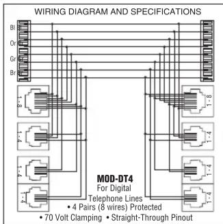
The MOD-DT4 module is designed to protect Digital Station (DS) Set phone lines. Station Set lines that leave the building are a pathway for surges (backdoor) to enter the phone system. This is why the lines FROM the Station Sets are connected to the LINE side of the module and the EQUIP side of the module is connected to the phone system. Multiple input & output jacks provide complete installation flexibility. The following diagram shows how the jacks/wires are interconnected. Different cables/connections can be split or combined to accommodate a variety of installations.
For example:
- Station Set lines from the phone system can be punched-down on the 110 jack on the EQUIP side and four RJ11 (2 wire) cords will connect from the LINE side to the Station Sets.
- Station Set lines from the phone system can be punched-down on the 110 jack on the EQUIP side and two RJ14 (4 wire) cords will connect from the LINE side (upper 2 jacks) to the Station Sets.
Caution: Never install telephones during a lightning storm.
Model: MOD-UTP (Isolated Loop Circuit Protector)

The MOD-UTP module is designed to protect networked computer equipment. It will protect one Ethernet 10/100 Base-T, Token Ring, Arcnet, or AppleTalk network line.

- Use a modular cord to connect the EQUIP modular jack to the equipment to be protected.
Please note: The protection circuitry will not work if the signal lines are reversed.
- Connect the network line from wall/floor jack to the LINE jack on the module.
Model: MOD-CAT5 (Isolated Loop Circuit Protector)

natural_image
Line drawing of a mechanical component with two coiled wires and a labeled section 'MOD-CAT5' (no text or symbols beyond label)The MOD-CAT5 module is designed for high-speed data applications-networks including CAT 5, fast Ethernet, ATM, and other high-speed active transport devices.
SPECIFICATIONS MOD-CAT5
For 10/100/1000 Base-T Ethernet
• 8 Wires (4 Pairs) Protected
- 19 Volt Clamping
- CAT5E Compliant
- Connect the CAT 5 cable connected on either side on the module to the wall/floor jack and then to the equipment to be protected. There is no "IN" or "OUT". MOD-CAT5 is bi-directional.
STV (Secondary Protector)

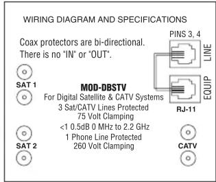
The MOD-DBSTV module provides protection for 3 SAT / CABLE / ANT and 1 telephone line.
- Connect the Satellite LNB or Cable TV coax cable from the wall/floor jack to one of the "F" connectors labeled SAT/CATV on the module
- Use a coax patch cord to connect the other SAT/CATV labeled modular "F" connector to the equipment to be protected.
- Repeat steps 1 and 2 for up to 2 additional satellite or cable TV lines.
- Connect the telephone line to the LINE jack on the module.
- Use a modular cord to connect the EQUIP modular jack to the equipment to be protected.
Note: This reminder is provided to call the CATV installer's attention to Article 820-40 of the NEC that provides guidelines for proper grounding and, in particular, specifies that the cable ground shall be connected to the grounding system of the building as close to the point of entry as possible.
Model: MOD-SPKP (Isolated Loop Circuit Protector)

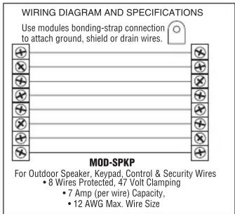
The MOD-SPKP module is designed to protect outdoor speaker, keypad, control and security wires (8 wires or 4 pairs). Equipment lines that lead outside the building are pathways for surges (sometimes called backdoor surges) to enter the equipment. This is why the lines FROM the outdoor equipment is connected to the LINE side of the module and the EQUIP side of the module is connected to the equipment.
1. Strip the ends of the individual wires about 1/4 inch. The screw clamp terminals will work with a range of wire sizes (up to 12AWG). Spade lugs are not required, but may be used.
- Connect the wires from the outdoor equipment to terminals on the LINE side of the module.
- Connect the wires from the EQUIP side of the module to the equipment.
- If the cable has a shield or drain wire, connect it to the modules bonding-strap connection located on the upper right portion of the module. If more than one module is connected to the AC base unit, placing this module at the top may allow for easier connection of shield or drain wires.
INS0769 REV .D
06/07
Brand : Panamax
Model : MOD-DT4
Category : Uncategorized