
1745DSTE - Uncategorized JUNG - Free user manual and instructions
Find the device manual for free 1745DSTE JUNG in PDF.


| Product Type | DALI-2 rotary controller TW (Tunable White) |
| Model Number | 1745DSTE (without integrated power supply) / 1746DSTE (Power DALI-2 rotary controller TW with integrated bus power) |
| Brand | JUNG |
| Rated Voltage (Power DALI-2) | AC 230 V ~, 50/60 Hz |
| Power Consumption (Power DALI-2) | Max. 2 W |
| DALI Bus Voltage | DC 16 V (typ.) |
| DALI Bus Current Consumption (DALI-2 rotary controller TW) | Max. 4 mA |
| Permitted Bus Power (Power DALI-2) | Max. 250 mA, guaranteed 52 mA |
| Maximum DALI Subscribers | 26 (Power DALI-2), up to 104 with parallel switching of 4 devices |
| Color Temperature Range | 2000 ... 10000 K |
| Ambient Temperature | -5 ... +45 °C |
| Installation Depth | Approx. 24 mm |
| Mounting | In appliance box according to DIN 49073 |
| Connection Terminals | Screw terminals for 1 × 0.5–4 mm² or 2 × 0.5–2.5 mm² |
| Operating Modes | Broadcast (factory), Group control, Input device (programmable) |
| Functions | Switching, dimming, color temperature adjustment (Tunable White), save switch-on brightness, save basic brightness, save color temperature limits |
| Communication | DALI-2 certified to IEC 62386-101, 103, 301, 302; multi-master capable |
| LED Indicator | For device localization (identify device) |
| Safety | Installation only by skilled electrician; disconnect power before working; short-circuit proof DALI power supply |
| Standards | CE, UKCA, EAC |
| Manufacturer | ALBRECHT JUNG GMBH & CO. KG, Volmestraße 1, 58579 Schalksmühle, Germany |
Frequently Asked Questions - 1745DSTE JUNG
User questions about 1745DSTE JUNG
0 question about this device. Answer the ones you know or ask your own.
Ask a new question about this device
Download the instructions for your Uncategorized in PDF format for free! Find your manual 1745DSTE - JUNG and take your electronic device back in hand. On this page are published all the documents necessary for the use of your device. 1745DSTE by JUNG.
USER MANUAL 1745DSTE JUNG
Operating instructions
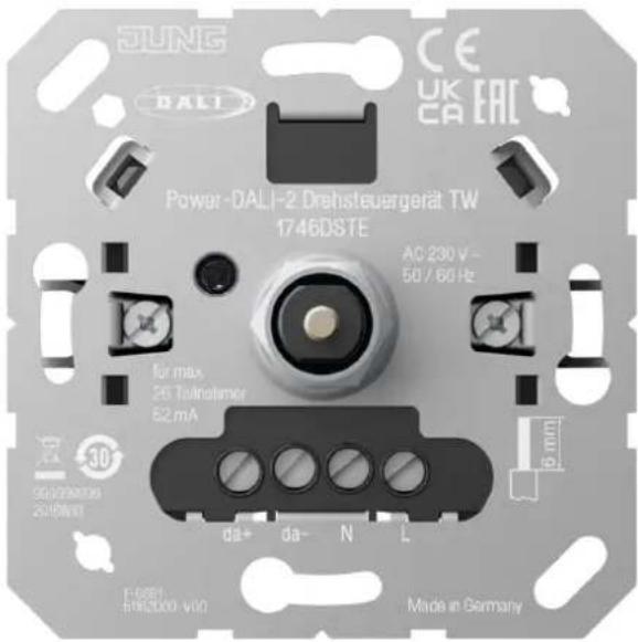
Power DALI-2 rotary controller TW
Art. no. 1746DSTE
DALI-2 rotary controller TW
Art. no. 1745DSTE

ALBRECHT JUNG GMBH & CO. KG
Vollmestraße 1
58579 Schalksmühle
GERMANY
Telefon: +49 2355 806-0
Telefax: +49 2355 806-204
kundencenter@jung.de
www.jung.de
Product image non-binding
23.09.2024
82408403 J0082408403
Table of contents
1 Safety instructions .... 3
2 Device components.... 3
3 Intended use.... 3
4 Product characteristics .... 4
5 Functional description.... 4
6 Operation.... 5
7 Information for electrically skilled persons.... 7
7.1 Mounting and electrical connection.... 7
7.2 Commissioning without programming.... 8
7.3 Commissioning via DALI programming device or central control 10
8 Technical data 11
9 Programming 12
10 Troubleshooting.... 15
11 Warranty 15
1 Safety instructions

Electrical devices may be mounted and connected only by electrically skilled persons.
Serious injuries, fire or property damage are possible. Please read and follow the manual fully.
Danger of electric shock. Always disconnect before carrying out work on the device or load. In so doing, take all the circuit breakers into account, which support dangerous voltages to the device and or load.
These instructions are an integral part of the product, and must remain with the customer.
2 Device components
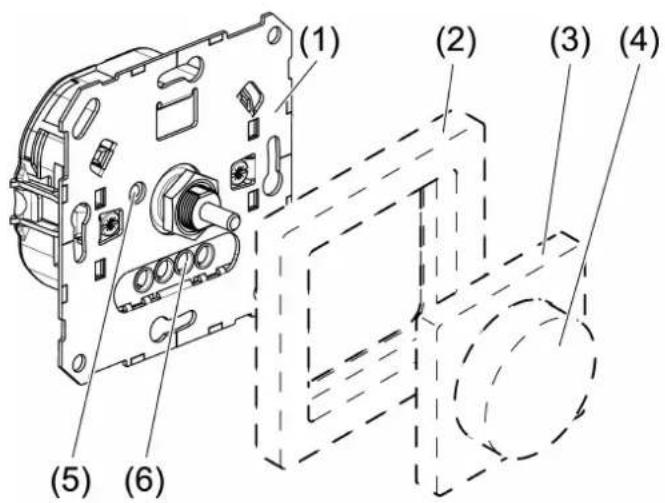
Figure 1: Device components
(1) Power DALI-2 rotary controller TW
(2) Frame
(3) Central plate
(4) Control knob
(5) LED
(6) Screw terminals
3 Intended use
– Brightness setting for luminaires with DALI interface
- Setting the colour temperature for luminaires with DALI Device Type 8 for Tunable White in accordance with IEC 62386-209
- Rotary control point (input device) for higher-level DALI-2 controllers
- Mounting in appliance box with dimensions according to DIN 49073
4 Product characteristics
Product characteristics without programming
– Certified DALI-2 control device to IEC62386-101, 103, 301, 302
– Power DALI-2 rotary controller TW: DALI-2 application controller with integrated bus power supply for up to 26 DALI subscribers
- Parallel switching of up to 4 DALI rotary control devices with bus power supply, with the option of supplying up to 104 DALI subscribers.
– DALI-2 rotary controller TW: DALI-2 application controller without bus power supply requires an external DALI power supply in accordance with IEC 62386-101
- Multi-master capable; several control units can be installed as application controllers in a DALI system
- LED for device localization
– DALI power supply, short-circuit proof
– Saving of basic brightness and switch-on brightness
– Saving of colour temperature limiting values
Further product characteristics through programming via DALI-2 control commands
- Suitable as a rotary control point (input device) for connection to central DALI-2 controls
– Supports four DALI-2 instances for adaptation to central control - Can be used to control a DALI-2 group
– Cyclical transmission of control commands to DALI operating devices can be activated
Behaviour after a mains voltage failure
In the broadcast and group control operating modes, the lighting is switched to the brightness and colour temperature present before the mains voltage failed.
If the device functions as an input device, the behaviour on the mains voltage return is determined by the higher-level DALI-2 controller.
5 Functional description
Operating modes
The device can be operated in different operating modes.
Broadcast control (factory settings):
The device functions as an application controller. Broadcast telegrams are sent out that apply to all devices connected in the DALI system. These include switching and setting the brightness/colour temperature of the lighting and setting the switch-on
brightness.
If there are multiple control points, saved settings are automatically adopted by the other control points.
Input device (programming necessary):
The device no longer sends control commands to DALI operating devices, but rather only telegrams to a higher-level DALI-2 controller. This control analyses the pressing or turning movements and then forwards control commands to the lighting.
To switch to this operating mode, the Application Controller must be deactivated via a DALI-2 control command. This is done using a DALI-2 programming device or a higher-level controller.
Group control (programming necessary):
The device sends telegrams as with broadcast control, but only in relation to the group.
To access this operating mode, the Operating mode of the device must be changed using a DALI-2 programming device (see Programming chapter). This is also done via DALI-2 control commands.
The group set in operating mode must correspond to the group of luminaires that is to be operated.
If another device is to be used as a control point for this DALI group, the Application Controller must be deactivated for this device so that it functions as Input device (see chapter "Programming" ▶ Page 14).
In order for the two devices to understand each other, the same Device Group must be programmed for both devices.
Cyclical transmission
In the as-delivered state, the device only sends control telegrams to DALI operating devices during operation.
However, there are also project designs in which it is desired for sent control telegrams to be repeated cyclically. During cyclical transmission, the control device that was operated last repeats the brightness and colour temperature on the DALI bus at 5-second intervals. This means that, for example, groups of luminaires or individual luminaires that have been enabled can light up again with the same brightness when the voltage is switched on, without any intervention required.
Cyclical transmission can be activated by programming the Operating mode (see Programming chapter).
6 Operation
The operation described applies to the as-delivered state for all connected subscribers (broadcast). If the device is programmed via a DALI programming tool or integrated into a central control, the settings programmed there apply.
Switching the light
■ Press the control knob.
Adjusting the brightness
■ Turn the control knob.
Turn slowly = Brightness change small
Turn quickly = Brightness change great
Setting the colour temperature
flowchart
graph TD
    A["Top Circle"] --> B["Left Arrow"]
    B --> C["Right Arrow"]
    C --> D["Bottom Circle"]
    D --> E["Center Arrow"]
    E --> F["Left Arrow"]
    style A fill:#f9f,stroke:#333
    style F fill:#bbf,stroke:#333
Figure 2
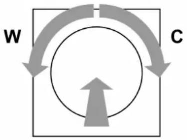
■ Turn pressed control knob.
Turn left (W) = warmer light (reduce colour temperature)
Turn right (C) = colder light (increase colour temperature)
Saving the switch-on brightness
If the lighting is not always to be switched on with the same brightness, then this can be saved as a switch-on brightness.
■ Switch on light.
■ Set required switch-on brightness.
■ Press the control knob briefly twice in succession (double-click).
The lighting briefly switches to maximum brightness twice. The switch-on brightness is saved.
If the lighting switches off after the double-click, then the time between the first and second presses was too long.
Deleting the switch-on brightness
■ Switch the light off.
■ Press the control knob briefly twice in succession (double-click).
After about 2 seconds the lighting switches to maximum brightness.
The switch-on brightness has been deleted. When the lighting is switched on, that brightness is set which existed the last time it was switched off.
7 Information for electrically skilled persons

DANGER!
Electric shock when live parts are touched.
Electric shocks can be fatal.
Always disconnect before carrying out work on the device or load. To do so, switch off all corresponding circuit breakers, secure them against being switched on again and check that there is no voltage. Cover up any adjacent live parts.
7.1 Mounting and electrical connection
Connecting and fitting the device
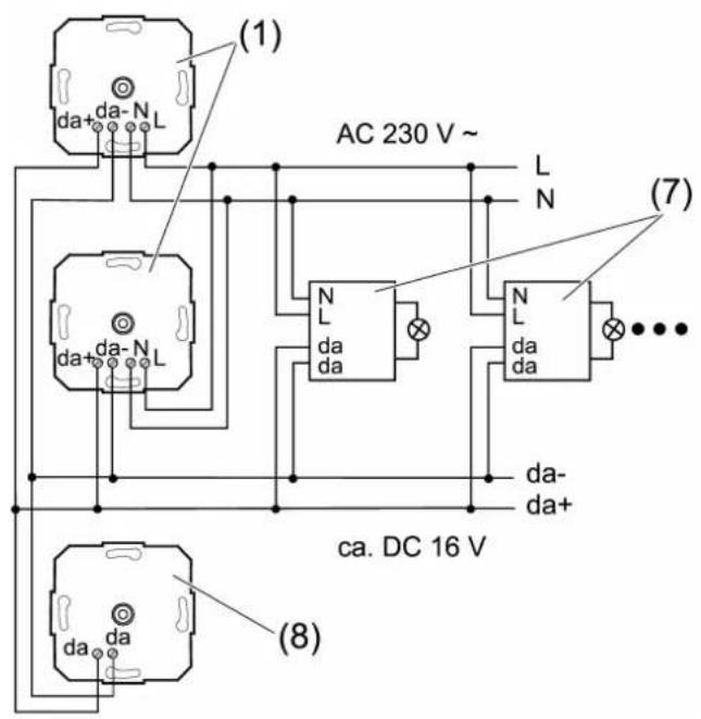
Figure 3: Broadcast mode connection example
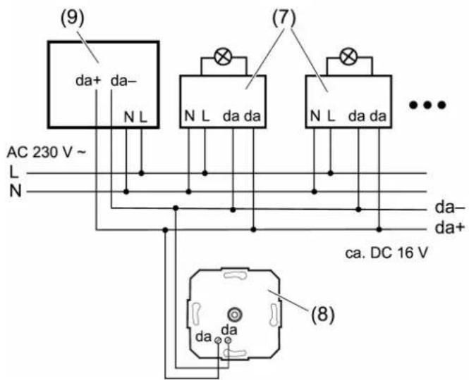
Figure 4: Connection diagram, operation as input device
(1) Power DALI-2 rotary controller TW (1746DSTE)
(7) DALI subscriber e.g. DALI-EVG, DALI Device Type 8 for Tunable White
(8) DALI-2 rotary controller TW (1745DSTE)
(9) Central control, e.g. KNX DALI-2 Gateway Multimaster
Control cable: appropriate type, cross-section and routing for the specifications for 230 V cables. DALI and mains voltage wires can be run together in a cable, e.g. NYM 5x1.5 mm ^4 . The connected DALI subscribers may be operated on different phases.
■ Connect Power DALI-2 rotary controller TW, DALI-2 rotary controller TW and DALI electronic ballast according to the connection examples (see figure 3) and (see figure 4). In so doing, observe the data of the electrical ballast manufacturer.
■ If multiple circuit breakers supply dangerous voltages to the device or load, couple the circuit breakers or label them with a warning to ensure tripping.
A combination of Power DALI-2 rotary controller TW and an external power supply is not permitted. If an external power supply is used, e.g. via a central control unit, the power supply must not be connected to the rotary control device (see figure 4).
7.2 Commissioning without programming
The device can be put into operation without an external programming tool or central control. It then controls all connected DALI broadcast operating devices. The following settings are optionally available for broadcast control or group control.
If there are multiple control points, saved settings are automatically adopted by the other control points.
Saving a basic brightness
The basic brightness should be set to a state that does not directly lead to an increase in brightness when turning the DALI rotary control device at minimum brightness.
■ Set lighting to minimum brightness.
■ Turn the DALI rotary control device to the point where the brightness starts to increase.
■ Press the control knob for longer than 10 seconds.
The lighting switches briefly off and on again. The basic brightness is saved.
Saving colour temperature limiting values
The setting range of the DALI rotary control device can be adjusted to the colour temperature of the luminaire using this setting.
When saving the colour temperature, you must ensure that the last turn of the pressed control knob (see figure 2) is made to the left for the warmest light colour (W) and to the right for the coldest light colour (C).
■ Turn pressed control knob to the left (W) until reaching the warmest light colour required, and hold it in this position for more than 10 seconds.
The light switches off three times and then switches on again. The warmest light colour is saved.
■ Turn pressed control knob to the right (C) until reaching the coldest light colour required, and hold it in this position for more than 10 seconds.
The light switches off three times and then switches on again. The coldest light colour is saved.
Deleting the basic brightness and colour temperature limiting values
■ Switch the lighting off.
■ Press the control knob for longer than 10 seconds.
Briefly switch the lighting to maximum brightness and then off again. The stored values are deleted.
In broadcast operation, a DALI reset is also sent to the DALI bus during deletion so that other rotary control devices also reset the limit values. This reset also resets the settings for all other operating or control devices on the DALI bus.
DALI subscribers of different manufacturers may deviate from the acknowledgements given here.
7.3 Commissioning via DALI programming device or central control
For operation of the device exclusively for control of a DALI group or for integration as Input device in a higher-level controller, programming with an external device is required (e.g. DALI USB interface art. no. 24138923 from Lunatone).
If the DALI rotary control device is addressed during commissioning via the DALI-2 command "Identify device", the integrated LED lights up for 10 seconds to identify the device.
Group control
An external DALI-2 programming device can be used to set the controller of a specific group of luminaires by changing Operating mode (see programming Operating mode).
If a second device is to be used for control of this group, the same device group must be set for this device as for the first device. However, the Application controller must also be deactivated so that this device functions as Input device Table : Programming [▶ Page 14).
Input device
In order to use the device purely as an input device for a higher-level controller, the device can be optimally commissioned with the higher-level controller, such as a DALI Gateway Colour (from Firmware version 2.0.0 and application programme version 2.2).
This requires deactivating the Application controller and setting the instances. This activates the command set that is understood by the higher-level controller (see Programming chapter).
8 Technical data
Power DALI-2 rotary controller TW
Rated voltage AC 230 V \~
Mains frequency 50 / 60 Hz
Power consumption Max. 2 W
Ambient temperature -5 ... +45 °C
Rated voltage DALI DC 16 V (typ.)
Permitted bus power Max. 250 mA
Guaranteed bus power 52 mA
Short-circuit current Max. 61 mA
Colour temperature setting 2000 ... 10000 K
Number of DALI subscribers max. 26
Number of active rotary control devices max. 4
Installation depth approx. 24 mm
DALI-2 rotary controller TW
(external DALI power supply required in accordance with IEC 62386-101)
Rated voltage DALI DC 16 V (typ.)
Current consumption Max. 4 mA
Ambient temperature -5 ... +45 °C
Colour temperature setting 2000 ... 10000 K
Installation depth approx. 24 mm
Clampable conductor cross-section (see figure 5)
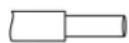
1 × 0,5 4 ~mm^2 2 × 0,5 2,5 ~mm^2
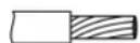
1 × 0,5 4 ~mm^2 2 × 0,5 2,5 ~mm^2
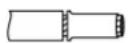
1 × 0,5 4 ~mm^2 2 × 0,5 1,5 ~mm^2
Figure 5: Clampable conductor cross-section
9 Programming
Programming the operating mode
In operating mode, you can set whether the device sends broadcast telegrams or transmits telegrams exclusively to an operating device group.
Both operating modes can work with or without cyclical transmission. When cyclical transmission is active, the telegrams are repeated at 5-second intervals.
With DALI-2 control commands, the operating mode is set once using an external DALI-2 programming tool. Here, the following two DALI-2 commands must be sent to the bus:
- The "DTR0" command is used to write the telegram of the desired operating mode, which is listed in the following table, to the register of the rotary control device.
- The "SET OPERATING MODE" command is used to transfer the operating mode from the register to the main memory of the device.
The device supports the following operating modes
| Operating mode Telegrams (hexadecimal) | |
| Broadcast no cyclical transmission (factory setting) | 00 |
| Group mode, Group0, cyclical transmission | 80 |
| Group mode, Group1, cyclical transmission | 81 |
| Group mode, Group...15, cyclical transmission | ... 8F |
| Group mode, Group0, no cyclical transmission | 90 |
| Group mode, Group1, no cyclical transmission | 91 |
| Group mode, Group15, no cyclical transmission | ... 9F |
| Broadcast, cyclical transmission | 00 |
Programming as input device: Instances
If the device is operated as an input device, programming must be used to define which commands are transferred to central control. With DALI-2, this occurs via so-called instances. Depending on the central control, one or more instances are activated during programming. Each time the device is operated, a so-called "event" is triggered, which is analysed by the central control.
Four instances can be activated in our device.
If the central control is another DALI rotary control device which controls an operating device group as an application controller, instances 0 and 2 must be activated and instances 1 and 3 deactivated (see □Table : Programming [▶ Page 14)).
Instance 0 = instance type 1 (push button):
This DALI-2 standard instance type is used to transmit the command to press the operating button to a central control. This instance should always be active if DALI devices are to be switched by pressing the button.
The following table shows which events are possible in this instance.
| Event name Telegram (binary) | |
| Button released 00 0000 0000 | |
| Button pressed 00 0000 0001 | |
| Brief press 00 0000 0010 | |
| Double press 00 0000 0101 | |
| Long press, start 00 0000 1001 | |
| Still pressed 00 0000 1011 | |
| Long press, stop 00 0000 1100 | |
| Button free 00 0000 1110 | |
| Button jammed 00 0000 1111 |
Instance 1 = Instance type 0 (Generic => Rotate with relative values)
Instance type 0 is an instance that is specified by the manufacturer. The instance evaluates the rotary operation of the control knob. Turning the control knob generates telegrams analogous to the direction of the rotary motion, thus enabling relative dimming. The following table provides information about the control telegrams. If several instances of instance type 0 are activated, operating errors occur.
| Event name Telegram (binary) | |
| Clockwise rotation starts 00 0000 0000 | |
| Anti-clockwise rotation starts 00 0000 0001 | |
| Stop rotation 00 0000 0010 |
Instance 2 = Instance type 0 (Generic => Rotate with relative values)
Similar to instance 1, instance 2 assesses the rotary motion of the control knob. However, not just the direction of rotation is transmitted here, the speed of rotation is as well.
Activation of this instance is necessary to ensure rotary operation as in broadcast operation.
| Event name Telegram (binary) | |
| Stop rotation 00 0000 0000 | |
| Turn quickly clockwise 00 0000 0001 | |
| Slowly rotate clockwise 00 0000 0010 | |
| Rotate clockwise in increments 00 0000 0011 | |
| Quickly rotate anti-clockwise 00 0000 0100 | |
| Slowly rotate anti-clockwise 00 0000 0101 | |
| Rotate anti-clockwise in increments 00 0000 0110 | |
Instance 3 = Instance type 2 (analogue input => turning with absolute values) This is a DALI-2 standard instance type. Absolute position values are sent with the rotary motion. The values are changed in large increments for a fast rotary motion and in small increments with a slow rotary motion. Once the maximum or minimum value has been reached, the same value is always sent for a further rotary motion.
Programming example
The following programming steps are necessary to realise group control via two control points:
| Device 1 (master) DALI | command Input example | Meaning |
| Application Controller must be activated (factory settings) | This device sends control commands for the luminaires. | |
| Assigning a device to a DALI group of lumin-aires | "DTR0" "SET OPERATING MODE" | Group 1 = 91 (Hex) The group number is written to the DTR0 register of the device and transferred to Operating Mode in the second step. |
| Saving setting permanently | "SAVE PER-SISTENT VARIABLES" | |
| Assigning device to a DALI-2 control device group | The devices communicate through using this group. |
| Device 2 (slave) Instance Event filter Meaning | |||
| Deactivate application controller | The device no longer sends commands directly to luminaires. | ||
| Assign device 2 to the same DALI-2 control device group as device 1 | This means that device 1 understands the operation of device 2 and can control luminaires. | ||
| Device 2 (slave) Instance | Event filter Meaning | ||
| Parameterise instances | Instance 0Event scheme:Device group addressing | Activate button releasedActivate button pressedDeactivate all other schemes | This setting causes the button press to be analysed. |
| Deactivate instance 1Activate instance 2Event scheme:Device group addressingDeactivate instance 3 | This setting causes the rotary movement to be analysed. | ||
10 Troubleshooting
The colour temperature cannot be changed
Cause 1: Before saving the colour temperature limiting values, the control knob was turned in the wrong direction.
Delete basic brightness and colour temperature limiting values. Then repeat the save procedure.
Cause 2: The activated luminaire does not include a DALI Device Type 8 for Tunable White in accordance with IEC 62386-209.
Exchange DALI subscriber.
Group control of the luminaires is no longer possible
Cause: A DALI-2 reset has been triggered by a DALI rotary dimming insert operating in broadcast control mode. As a result, the group membership of the operating devices was deleted.
The groups must be programmed again.
11 Warranty
The warranty is provided by the specialist trade in accordance with statutory requirements.
ALBRECHT JUNG GMBH & CO. KG
Volmestraße 1
58579 Schalksmühle
GERMANY
Telefon: +49 2355 806-0
Telefax: +49 2355 806-204
kundencenter@jung.de
www.jung.de

- Operating instructions
- Table of contents
- Safety instructions
- Device components
- Intended use
- Product characteristics
- Product characteristics without programming
- Further product characteristics through programming via DALI-2 control commands
- Behaviour after a mains voltage failure
- Functional description
- Operating modes
- Broadcast control (factory settings):
- Cyclical transmission
- Operation
- Switching the light
- Adjusting the brightness
- Setting the colour temperature
- Saving the switch-on brightness
- Deleting the switch-on brightness
- Information for electrically skilled persons
- DANGER!
- Mounting and electrical connection
- Commissioning without programming
- Saving a basic brightness
- Saving colour temperature limiting values
- Deleting the basic brightness and colour temperature limiting values
- Commissioning via DALI programming device or central control
- Group control
- Input device
- Technical data
- Programming
- Programming the operating mode
- Programming as input device: Instances
- Programming example
- Troubleshooting
- Warranty
Brand : JUNG
Model : 1745DSTE
Category : Uncategorized