
MV8M-140WV2RN8 - Heat pump MIDEA - Free user manual and instructions
Find the device manual for free MV8M-140WV2RN8 MIDEA in PDF.


| Product Type | Ductless Mini-Split Heat Pump |
| Brand | Midea |
| Model | MV8M-140WV2RN8 |
| Cooling Capacity (BTU/h) | 14,000 |
| Heating Capacity (BTU/h) | 15,000 |
| Power Supply | 230V / 60Hz |
| Energy Efficiency Ratio (EER) | 12.0 |
| COP (Heating) | 3.5 |
| Refrigerant | R-410A |
| Compressor Type | Inverter |
| Indoor Unit Dimensions (W×H×D) | 39.4 × 11.8 × 8.7 in (1000 × 300 × 220 mm) |
| Outdoor Unit Dimensions (W×H×D) | 34.6 × 30.3 × 13.4 in (880 × 770 × 340 mm) |
| Indoor Unit Weight | 28.7 lb (13 kg) |
| Outdoor Unit Weight | 77.2 lb (35 kg) |
| Noise Level (Indoor) | 26 – 42 dB(A) |
| Noise Level (Outdoor) | 55 dB(A) |
| Air Flow Rate | 350 CFM |
| Operating Temperature Range | Cooling: 17°F to 115°F; Heating: -13°F to 86°F |
| Filter Cleaning | Every 2 weeks; washable |
| Safety | Turn off power before servicing; use certified electrician |
Frequently Asked Questions - MV8M-140WV2RN8 MIDEA
User questions about MV8M-140WV2RN8 MIDEA
0 question about this device. Answer the ones you know or ask your own.
Ask a new question about this device
Download the instructions for your Heat pump in PDF format for free! Find your manual MV8M-140WV2RN8 - MIDEA and take your electronic device back in hand. On this page are published all the documents necessary for the use of your device. MV8M-140WV2RN8 by MIDEA.
USER MANUAL MV8M-140WV2RN8 MIDEA
INSTALLATION AND OWNER'S MANUAL
Full DC Inverter V8 R32 Series Mini VRF (ODU)
natural_image
Line drawing of a dual-panel air conditioner unit with fan blades and ventilation slots (no text or symbols)IMPORTANT NOTE:
Original instructions
Thank you very much for purchasing our air conditioner.
Before using your air conditioner, please read this manual carefully and retain it for future reference.
The figures shown in this manual are for reference purposes only and may be slightly different from the actual product.
CONTENTS
OWNER'S MANUAL 01
1 BEFORE OPERATING 01
2 OPERATIONS 16
3 MAINTENANCE AND REPAIR 17
4 TROUBLESHOOTING 19
5 CHANGING INSTALLATION SITE 24
6 DISPOSAL 24
INSTALLATION MANUAL 25
1 PRECAUTIONS 25
2 PACKING BOX 26
3 OUTDOOR UNIT 27
4 PREPARATIONS BEFORE INSTALLATION 27
5 OUTDOOR UNIT INSTALLATION 31
6 ELECTRICAL WIRING 35
7 CONFIGURATION 40
8 COMMISSIONING 46
9 PRECAUTIONS ON REFRIGERANT LEAKAGE 48
10 TURN OVER TO CUSTOMER 49
11 TECHNICAL DATA 50

NOTE
The figures in this manual are for explanation purposes only. They may be slightly different from the air conditioner you purchased (depending on the model). The actual shape shall prevail. The single-phase units comply with IEC 61000-3-12.
OWNER'S MANUAL
1 BEFORE OPERATING
To prevent injury to the user or others and property damage, the following instructions must be followed. Ignoring these instructions may cause harm or damage.
i INFORMATION
Read these instructions carefully before operation. And keep this manual handy for future reference.
WARNING
- Any person who is involved with working on or opening a refrigerant circuit should hold a current valid certificate from an industry-accredited assessment authority, which authorizes their competence to handle refrigerants safely in accordance with an industry recognized assessment credential.
• Servicing shall only be performed as recommended by the equipment manufacturer. - Maintenance and repair requiring the assistance of other skilled personnel shall be carried out under the supervision of a person competent in the use of flammable refrigerants.
1.1 Overview
The safety precautions listed here are divided into the following types. They are quite important, so be sure to follow them carefully.
Meanings of WARNING, CAUTION, NOTE and INFORMATION symbols.
WARNING
A situation that may lead to severe injury or death.
CAUTION
A situation that may lead to mild or moderate injury.
NOTE
A situation that may cause damage to the equipment or loss of property.
i INFORMATION
Indicates a useful hint or additional information.
Explanation of symbols displayed on the application
 | CAUTION | This symbol indicates that the operation manual should be read carefully. |
 | CAUTION | This symbol indicates that service personnel should be handling this equipment while referencing the installation manual. |
 | CAUTION | This symbol indicates that additional information is available in documents such as the operating manual or installation manual. |
1.2 Important Safety Information
WARNING
- This appliance can be used by children ages 8 and above and persons with reduced physical, sensory or mental capabilities or who lack experience and knowledge only if they are supervised or have been given instruction concerning the use of the appliance in a safe way and understand the hazards involved.
Children shall not play with the appliance. Children shall not clean or maintain the appliance without supervision.
- This appliance is not intended for use by persons (including children) with reduced physical, sensory or mental capabilities, or persons who lack experience and knowledge, unless they are supervised or have been given instructions concerning the use of the appliance by a person responsible for their safety.
– Children should be supervised to ensure that they do not play with the appliance.
- The split units shall only be connected to an appliance compatible with the same refrigerant.
- The units 8-18 kW are split unit air conditioners, complying with split unit requirements of this International standard, and must only be connected to the units that have been confirmed as complying with the corresponding split unit requirements of this International standard.
- Ask your dealer to assist in the installation of the air conditioner.
Incomplete installation performed by yourself may result in a water leakage, electric shock, and fire.
- Ask your dealer for assistance with improvement, repair, and maintenance.
Incomplete improvement, repair, and maintenance may result in a water leakage, electric shock, and fire.
- To avoid electric shock, fire or injury, please turn off the power supply and call your dealer for instructions if you detect any abnormalities such as a burning smell
- Never let the indoor unit or the remote controller get wet.
This could lead to electric shock or fire.
- Never press the button of the remote controller with a hard, pointed object.
The remote controller may be damaged.
- Never replace a fuse with a fuse that has an incompatible rated current or other wires when a fuse blows out.
The use of wire or copper wire may cause the unit to break down or cause a fire.
- Exposing your body to the air flow of the air conditioner for long periods of time may be harmful to your health
- Do not insert fingers, rods or other objects into the air inlet or outlet.
When the fan is in operation, it will cause injury.
- Never use a flammable spray, such as hair spray or lacquerer paint, near the unit. It may cause a fire.
WARNING
- Prior to beginning work on systems containing flammable refrigerants, safety checks are necessary to minimize the risk of ignition
- When repairing the refrigerating system, comply with the following precautions prior to conducting work on the system:
- shall be undertaken according to controlled procedures so as to minimize the risk of the presence of flammable gases or vapors while the work is being performed.
– All maintenance staff and others working in the local area shall be instructed on the nature of work being carried out. Work in confined spaces shall be avoided.
- The area shall be checked with an appropriate refrigerant detector prior to and during work, to ensure the technician is aware of potentially toxic or flammable environment. Ensure that the leak detection equipment being used is suitable for use with all applicable refrigerants, i.e. non-sparking, adequately sealed or intrinsically safe.
- If any hot work is to be conducted on the refrigerating equipment or any associated parts, appropriate fire extinguishing equipment shall be available and easily accessible. Have a dry powder or CO2 fire extinguisher adjacent to the charging area.
- When carrying out work in relation to a refrigerating system that involves exposing any pipe work, no sources of ignition shall be used in such a manner that it may lead to the risk of fire or explosion. All possible ignition sources, including cigarette smoking, should be kept sufficiently far away from the site of installation, repair, or removal and disposal of the unit, during which refrigerant can possibly be released into the surrounding space. Prior to beginning work, the area around the equipment is to be surveyed to make sure that there are no flammable hazards or ignition risks. "No Smoking" signs shall be clearly displayed.
- Ensure that the area is in the open or that it is adequately ventilated before opening the system or conducting any hot work. A degree of ventilation shall continue during the period that the work is carried out. The ventilation should safely disperse any released refrigerant and preferably expel it externally into the surroundings.
- Where electrical components are being changed, they shall be fit according to their purpose and to the correct specification. At all times the manufacturer's maintenance and service guidelines shall be followed. If in doubt, consult the manufacturer's technical department for assistance. The following checks shall be applied to installations using flammable refrigerants:
- The actual refrigerant charge is in accordance with the room size within which the refrigerant containing parts are installed;
– The ventilation machinery and outlets are operating adequately and are not obstructed;
- If an indirect refrigerating circuit is being used, the secondary circuit shall be checked for the presence of refrigerant;
– Equipment marking must remain visible and legible. Markings and signs that are illegible shall be corrected;
- Refrigerating pipe or components are installed in a position where they are unlikely to be exposed to any substances which may corrode refrigerant containing components, unless the components are constructed of materials that are inherently resistant to corrosion or are suitably protected against corrosion.
- Repair and maintenance of electrical components shall include initial safety checks and component inspection procedures. If a fault exists that could compromise safety, then no electrical supply shall be connected to the circuit until the fault has been dealt with satisfactorily. If the fault cannot be corrected immediately but it is necessary to continue operation, an adequate temporary solution shall be used. This shall be reported to the owner of the equipment so that all parties are advised. Initial safety checks shall include:
– That capacitors are discharged: this shall be done in a safe manner to avoid the possibility of sparking;
- That no live electrical components and wiring are exposed while charging, recovering or purging the system;
– That there is continuity of grounding.
- When repairing sealed components, all electrical supplies shall be disconnected from the equipment being worked upon prior to any removal of sealed covers, etc. If it is absolutely necessary to have an electrical supply to the equipment during servicing, then a permanently operating form of leak detection shall be installed at the most critical point to warn of a potentially hazardous situation.
- Particular attention shall be paid to the following to ensure that by working on electrical components, the casing is not altered in such a way that the level of protection is affected. This shall include damage to cables, an excessive amount of connections, terminals not made to their original specification, damage to seals, incorrect fitting of glands, etc.
- Ensure that the apparatus is mounted securely.
- Ensure that seals or sealing materials have not degraded to the point that they no longer prevent the ingress of flammable materials. Replacement parts shall conform with the manufacturer's specifications.
- Do not apply any permanent inductive or capacitance loads to the circuit without ensuring that this will not exceed the permissible voltage and current permitted for the equipment in use.
- Intrinsically safe components are the only types that can be worked on while live in the presence of flammable gases. The test apparatus shall be at the correct rating.
- Replace components only with parts specified by the manufacturer. Other parts may result in the ignition of refrigerant which has leaked into the surroundings.
- Check that cabling will not be subject to wear, corrosion, excessive pressure, vibration, sharp edges or any other adverse environmental effects. The check shall also take into account the effects of aging or continual vibration from sources such as compressors or fans.
- Under no circumstances shall potential sources of ignition be used while searching for or detection of refrigerant leaks. A halide torch (or any other detector using a naked flame) shall not be used.
- Electronic leak detectors may be used to detect refrigerant leaks but, in the case of flammable refrigerants, the sensitivity may not be adequate, or may need re-calibration. (Detection equipment shall be calibrated in a refrigerant-free area.) Ensure that the detector is not a potential source of ignition and is suitable for the refrigerant used. Leak detection equipment shall be set at a percentage of the LFL of the refrigerant and shall be calibrated for the refrigerant employed, and the appropriate percentage of gas (25 % maximum) is confirmed.
- If a leak is suspected, all naked flames shall be removed/extinguished.
- If a leakage of refrigerant which requires brazing is found, all of the refrigerant shall be recovered from the system, or isolated (by means of shut off valves) in a part of the system remote from the leak.
- When opening the refrigerant circuit to make repairs – or for any other purpose – conventional procedures shall be used. However, for flammable refrigerants it is important that best practice is followed since flammability is a consideration. The following procedure shall be followed:
- Remove refrigerant;
– Purge the circuit with inert gas;
- Evacuate;
– Purge with inert gas;
- Open the circuit by cutting or brazing.
- The refrigerant charge shall be recovered into the correct recovery cylinders. The system shall be "flushed" with OFN to render the unit safe. This process may need to be repeated several times. Do not use compressed air or oxygen for this task.
- Flushing shall be achieved by breaking the vacuum in the system with OFN and continuing to fill until a working pressure is achieved, then venting to the surroundings, and finally pulling down to a vacuum. This process shall be repeated until no refrigerant is within the system. When the final OFN charge is used, the system shall be vented down to atmospheric pressure to enable work to take place. This operation is absolutely vital if brazing operations on the pipework are to take place.
- Ensure that the outlet for the vacuum pump is not close to any ignition sources and there is ventilation available.
- Ensure that contamination of different refrigerants does not occur when using charging equipment. Hoses or lines shall be as short as possible to minimise the amount of refrigerant they contain.
• Cylinders shall be kept upright. - Ensure that the refrigeration system is grounded prior to charging the system with refrigerant.
- Label the system when charging is complete (if it is not already labeled).
• Take extreme care not to overfill the refrigeration system. - Prior to recharging the system it shall be pressure tested with OFN. The system shall be leak tested on completion of charging but prior to commissioning. A follow up leak test shall be carried out prior to leaving the site.
- Before carrying out this procedure, it is essential that the technician is completely familiar with the equipment and all its detail. It is recommended that all refrigerants are recovered safely. Prior to the task being carried out, an oil and refrigerant sample shall be taken in case analysis is required prior to re-use of reclaimed refrigerant. It is essential that electrical power is available before the task is commenced.
a) Become familiar with the equipment and its operation.
b) Isolate system electrically.
c) Before attempting the procedure ensure that: - mechanical handling equipment is available, if required, for handling refrigerant cylinders;
– all personal protective equipment is available and being used correctly;
– the recovery process is supervised at all times by a competent person;
– recovery equipment and cylinders conform to the appropriate standards.
d) Pump down refrigerant system, if possible.
e) If a vacuum is not possible, make a manifold so that refrigerant can be removed from various parts of the system.
f) Make sure that the cylinder is situated on the scales before recovery takes place.
g) Start the recovery machine and operate it in accordance with the manufacturer's instructions.
h) Do not overfill cylinders. (No more than 80 % volume liquid charge).
i) Do not exceed the maximum working pressure of the cylinder, even temporarily.
j) When the cylinders have been filled correctly and the process has been completed, make sure that the cylinders and the equipment are removed from site promptly and all isolation valves on the equipment are closed off.
k) Recovered refrigerant shall not be charged into another refrigeration system unless it has been cleaned and checked.
- Equipment shall be labeled stating that it has been de-commissioned and emptied of refrigerant. The label shall be dated and signed. Ensure that there are labels on the equipment stating the equipment contains flammable refrigerant.
- When removing refrigerant from a system, either for servicing or decommissioning, it is recommended that all refrigerants are removed safely.
- When transferring refrigerant into cylinders, ensure that only appropriate refrigerant recovery cylinders are used. Ensure that the correct number of cylinders for holding the total system charge is available. All cylinders to be used are designated for the recovered refrigerant and labeled for that refrigerant (i.e. special cylinders for the recovery of refrigerant). Cylinders shall be complete, with pressure-relief valves and associated shut-off valves in good working order. Empty recovery cylinders are evacuated and, if possible, cooled before recovery occurs.
- Recovery equipment shall be in good working order and have an easily accessible set of instructions concerning the equipment. and the equipment shall be suitable for the recovery of all appropriate refrigerants including, when applicable, flammable refrigerants. In addition, a set of calibrated weighing scales shall be available and in good working order. Hoses shall be complete with leak-free disconnect couplings and in good condition. Before using the recovery machine, check that it is in satisfactory working order, has been properly maintained and that any associated electrical components are sealed to prevent ignition in the event of a refrigerant release. Consult the manufacturer if assistance is required.
- The recovered refrigerant shall be returned to the refrigerant supplier in the correct recovery cylinder, and the relevant waste transfer note arranged. Do not mix refrigerants in recovery units and especially not in cylinders.
- If compressors or compressor oils will be removed, ensure that they have been evacuated to an acceptable level to make certain that flammable refrigerant does not remain within the lubricant. The evacuation process shall be carried out prior to returning the compressor to the suppliers. Electric heating will only be employed on the compressor body to accelerate this process. When oil is drained from a system, it shall be carried out safely.
WARNING
- The maximum operating pressure of the application is 43 bar, which must be considered when connecting to any condenser unit or evaporator unit.
- The application shall only be connected to an appliance suitable for the same refrigerant.
- The units (8-18kW) are partial unit air conditioners, complying with partial unit requirements of this International Standard, and must only be connected to other units that have been confirmed as complying to corresponding partial unit requirements of this International Standard.
WARNING
- Never touch the air outlet or the horizontal blades while the swing flap is in operation. Your fingers may become caught or the unit may break down.
- Never put any objects into the air inlet or outlet. Objects touching the fan at high speed can be dangerous.
- Never inspect or service the unit by yourself. Ask a qualified service person to perform this task.
- Do not dispose of this product as unsorted municipal waste. This waste should be collected separately for special treatment.
Do not dispose of electrical app unsorted municipal waste. Use separate collection facilities. Contact your local government for information regarding the connection systems available
- If electrical appliances are disposed of in landfills or dumps, hazardous substances can leak into the groundwater and get into the food chain, harming your health and well-being.
- To prevent refrigerant leak, contact your dealer. When the system is installed and operates in a small room, it is required to maintain the concentration of the refrigerant below the limit, in case a leak occurs. Otherwise, oxygen in the room may be affected, resulting in a serious accident.
- The refrigerant in the air conditioner is safe and normally does not leak. If the refrigerant leaks into the room and comes into contact with the fire of a burner, a heater or a cooker, a harmful gas could be released.
- Turn off any combustible heating devices, ventilate the room, and contact the dealer where you purchased the unit. Do not use the air conditioner until a service person confirms that the refrigerant leak is repaired.
- Keep ventilation openings clear of obstruction.
CAUTION
- Do not use the air conditioner for other purposes. In order to avoid any quality deterioration, do not use the unit for the cooling of precision instruments, food, plants, animals or works of art.
- Before cleaning, be sure to stop the operation, turn the breaker off or unplug the supply cord. Otherwise, electric shock and injury may occur.
-
In order to avoid electric shock or fire, make sure that an earth leak detector is installed.
-
Be sure the air conditioner is grounded. In order to avoid electric shock, make sure that the unit is grounded and that the earth wire is not connected to a gas or water pipe, lightning conductor or telephone earth wire.
- In order to avoid injury, do not remove the fan guard of the outdoor unit.
- Do not operate the air conditioner with a wet hands. An electric shock may happen.
- Do not touch the heat exchanger fins. These fins are sharp and could cut you.
- Do not place items which might be damaged by moisture under the indoor unit.
Condensation may form if the humidity is above 80%, the drain outlet is blocked or the filter is polluted.
• After extended use, inspect the unit stand and fitting for damage. If damaged, the unit may fall and cause injury. - To avoid oxygen deficiency, ventilate the room sufficiently if equipment with a burner is used together with the air conditioner.
- Arrange the drain hose to ensure smooth drainage. Incomplete drainage may cause wetting of the building, furniture, etc.
- Never touch the internal parts of the controller. Do not remove the front panel. Some parts inside are dangerous to touch, and machine troubles may occur.
- Never expose little children, plants or animals directly to the air flow. Adverse influence to little children, animals and plants may occur.
- Do not allow a child to climb on the outdoor unit and avoid placing any objects on it. Injury may occur due to falling or tumbling.
CAUTION
- Do not operate the air conditioner when using a room fumigation - type insecticide. Failure to observe this precaution could cause the chemicals to become deposited in the unit, which could endanger the health of those who are hypersensitive to chemicals.
-
Do not place appliances which produce open flame in places exposed to the air flow from the unit or under the indoor unit. It may cause incomplete combustion or deformation of the unit due to the heat.
-
Do not install the air conditioner in a location where flammable gas may leak out. If the gas leaks out and stays around the air conditioner, a fire may break out.
- When the combination ratio of IDUs is greater than or equal to 110%, in order to ensure the capacity of the machine, try to turn on the indoor units at different time.
- The outdoor unit window-shades should be cleaned periodically to prevent jamming.
This window-shapes is the heat dissipation outlet of components, if it is jammed, it will cause the components shorten their service life spans because of being overheated for an extended period.
- The temperature of refrigerant circuit will be high. Please keep the interconnection cable away from the copper tube.
- The sound pressure level is below 70 dB(A).
- This appliance is intended to be used by expert or trained users in shops, in light industry and on farms, or for commercial use by lay persons.
1.3 Instructions for Application Using R32 Refrigerant
WARNING
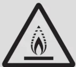
The application uses R32 refrigerant.
natural_image
Warning symbol depicting flame inside a triangle (no text or numbers)Caution: Risk of fire
(for IEC 60335-2-40: 2018 only)
WARNING
The application uses R32 refrigerant.
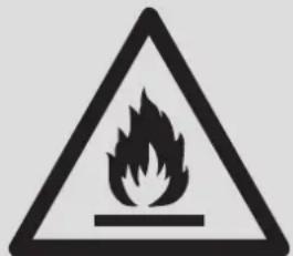
Caution: Risk of fire
(for IEC/EN 60335-2-40 except IEC 60335-2-40: 2018)
WARNING
- Do not use means to accelerate the defrosting process or to clean, other than those recommended by the manufacturer.
- The appliance shall be stored in a room that does not have continuously operating ignition sources (for example: open flames, an operating gas appliance or an operating electric heater).
• Do not pierce or burn the unit. - Be aware that refrigerants may be odorless.
WARNING
- Appliance shall be installed, operated and stored in a room that meets special requirements and has an area limit as shown in sections 1.3.1.
1.3.1 System layout requirements
1.3.1.1 Unit installation requirements
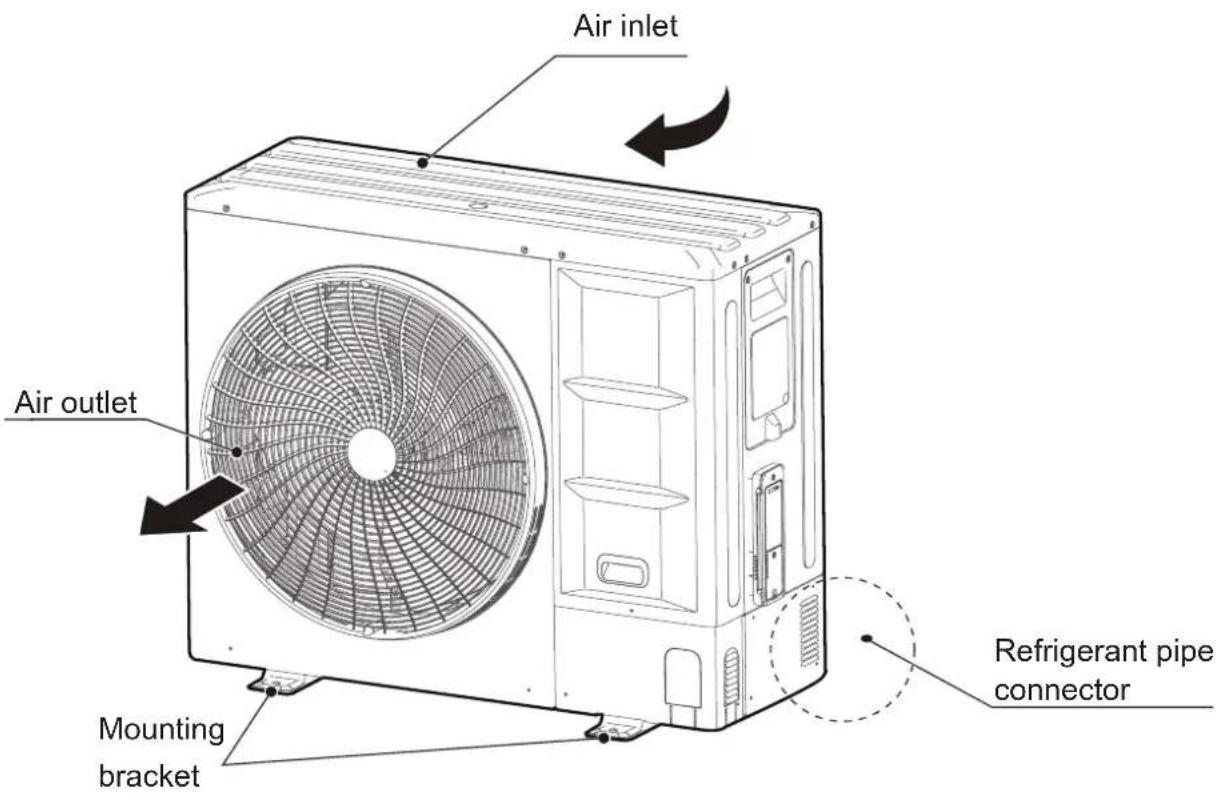
The outdoor unit shall be located in a well-ventilated location other than the occupied space, such as in the open air.
For installation of the indoor unit, refer to the corresponding installation and operation manual.
If an indoor unit is installed in an unventilated area, the area shall be so constructed that should any refrigerant leak, it will not stagnate so as to create a fire or explosion hazard.
WARNING
- The appliance shall be stored in a well-ventilated area where the room size corresponds to the room area as specified for operation.
- The appliance shall be stored in a room that does not have continuously operating open flames (for example an operating gas appliance) and ignition sources (for example, an operating electric heater).
1.3.1.2 Piping installation requirements
Low temperature solder alloys, such as lead/tin alloys, are not acceptable for pipe connections.
Reusable mechanical connectors and flared joints are not allowed indoors.
(EN 60335-2-40 Standard Requirements).
Mechanical connectors used indoors shall comply with ISO 14903. When mechanical connectors are reused indoors, sealing parts shall be renewed. When flared joints are reused indoors, the flaring part shall be re-fabricated.
Flexible refrigerant connectors (such as connecting lines between the indoor and outdoor unit) that may become displaced during normal operations shall be protected against mechanical damage.
(IEC 60335-2-40 Standard Requirements).
The refrigerating systems shall use only permanent joints indoors except for site-made joints directly connecting the indoor unit to the refrigerant piping, or factory made mechanical joints in compliance with ISO 14903.
(IEC 60335-2-40 Standard Requirements).
Refrigerant tubing shall be protected or enclosed to avoid damage.
Equipment pipes in the occupied space in question must be installed in such a way that it is protected against accidental damage.
NOTE
- Installation of pipe-work shall be kept to a minimum.
- Pipework shall be protected from physical damage and shall not be installed in an unventilated space, if that space is smaller than Amin in sections 1.3.1.3 and 1.3.1.4.
- Compliance with national gas regulations shall be observed;
- Mechanical connections made shall be accessible for maintenance purposes.
1.3.1.3 Refrigerant charge and room area limitations (strategy 1)
The system uses R32 refrigerant which is classified as class A2 and is flammable under EN 60335-2-40. Follow the requirements below to ensure that the system complies with legislation.
The total amount of refrigerant in the system shall be less than or equal to the maximum refrigerant charge. The maximum refrigerant charge depends on the amount of space in the rooms being served by the system.
The room area (A) shall be defined as the room area enclosed by the projection to the base of the walls, partitions and doors of the space in which the appliance is installed.
NOTE
- The space considered shall be any space which contains refrigerant-containing parts or into which refrigerant could be released.
- The room area (A) of the smallest, enclosed, occupied space shall be used in the determination of the refrigerant quantity limits.
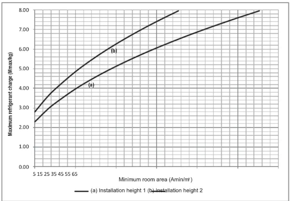
In addition, the maximum refrigerant charge is also related to the installation height of the indoor units. The correspondence of the maximum refrigerant charge with the minimum room area (Amin) is shown in Figure 1-1 and Table 1-1. And different values are used for different indoor unit installation heights:
- If installation height is greater than or equal to 1.8 m, but less than 2.2 m, use the refrigerant charge limitation of the graph for installation height 1.
- If installation height is not less than 2.2 m, use the refrigerant charge limitation of the graph for installation height 2.
NOTE
- The indoor unit installation height cannot be less than 1.8 m. For more detailed instructions on the installation height of the indoor units, please refer to the corresponding installation and operations manual.
- If the installation height of the indoor unit is less than 1.8 m, please contact your installer or dealer to receive more information and professional advice.
line
| Minimum room area (Amin/m²) | Maximum refrigerant charge (Mmax/kg) - Installation height 1 | Maximum refrigerant charge (Mmax/kg) - Installation height 2 | | --------------------------- | --------------------------------------------------------------- | --------------------------------------------------------------- | | 5 | 2.80 | 2.30 | | 15 | 3.50 | 2.90 | | 25 | 4.20 | 3.60 | | 35 | 4.90 | 4.30 | | 45 | 5.60 | 4.90 | | 55 | 6.30 | 5.50 | | 65 | 7.00 | 6.10 | | 75 | 7.70 | 6.80 | | 85 | 8.40 | 7.50 | | 95 | 9.10 | 8.20 |Figure 1-1
Table 1-1
| Amin/m2 | Mmax/kg-(a)/(b) | Amin/m2 | Mmax/kg-(a)/(b) | Amin/m2 | Mmax/kg-(a)/(b) |
| 4 2.048/2.503 23 4.911/6.003 42 6.637/7.956 | |||||
| 5 2.29/2.798 24 5.017/6.132 43 6.715/7.956 | |||||
| 6 2.508/3.066 25 5.12/6.258 44 6.793/7.956 | |||||
| 7 2.709/3.311 26 5.222/6.382 45 6.87/7.956 | |||||
| 8 2.896/3.54 27 5.321/6.504 46 6.946/7.956 | |||||
| 9 3.072/3.755 28 5.419/6.623 47 7.021/7.956 | |||||
| 10 3.238/3.958 29 5.515/6.74 48 7.095/7.956 | |||||
| 11 3.396/4.151 30 5.609/6.856 49 7.169/7.956 | |||||
| 12 3.547/4.336 31 5.702/6.969 50 7.241/7.956 | |||||
| 13 3.692/4.513 32 5.793/7.08 51 7.313/7.956 | |||||
| 14 3.832/4.683 33 5.883/7.19 52 7.385/7.956 | |||||
| 15 3.966/4.847 34 5.971/7.298 53 | 7.455/7.956 | ||||
| 16 4.096/5.006 35 6.058/7.405 54 7.525/7.956 | |||||
| 17 4.222/5.161 36 6.144/7.51 55 7.595/7.956 | |||||
| 18 4.345/5.31 37 6.229/7.614 56 7.664/7.956 | |||||
| 19 4.464/5.456 38 6.313/7.716 57 7.732/7.956 | |||||
| 20 4.58/5.597 39 6.395/7.817 58 7.799/7.956 | |||||
| 21 4.693/5.736 40 6.477/7.916 59 7.866/7.956 | |||||
| 22 4.803/5.871 41 6.557/7.956 60 7.933/7.956 | |||||
| ≥61 7.956/7.956 | |||||
| (a): The IDU installation height between 1.8 m and 2.2 m(b): The IDU installation height not less than 2.2 m | |||||
As shown above:
1) Curve (a) is refrigerant charge limitation for the indoor unit installation height between 1.8 m and 2.2 m.
2) Curve (b) is refrigerant charge limitation for the indoor unit installation height not less than 2.2 m.
NOTE
- The maximum refrigerant charge is related to types of the indoor units, which have different installation heights.
- The lowest maximum allowable charge of all rooms shall be used.
NOTE
- The maximum refrigerant limit described above applies to unventilated areas. For adding additional measures, such as areas with mechanical ventilation, please refer to applicable legislation for the maximum refrigerant limit.
CAUTION
- The system also has a maximum design refrigerant charge limit of 12 kg, which cannot be exceeded under any circumstances.
Determine the charge limit for the refrigerating system as the smaller of:
1) The maximum refrigerant charge (Mmax) in the system from the above room area limitations.
2) The maximum refrigerant charge (Mmax) with additional measures, such as areas with mechanical ventilation.
3) 12 kg from the limit of the application.
1.3.1.4 Refrigerant charge and room area limitations (strategy 2)
In IEC 60335-2-40, R32 refrigerant is classified as class A2L, which is mildly flammable. And the system meets the requirements of enhanced tightness refrigerating systems. Therefore, R32 refrigerant is suitable for systems needing additional refrigerant charge and which will limit room area strategy.
Similarly, the total amount of refrigerant in the system shall be less than or equal to the maximum refrigerant charge. The maximum refrigerant charge depends on the space of the rooms being served by the system.
NOTE
- The space considered shall be any space which contains refrigerant-containing parts or into which refrigerant could be released.
- The room area (A) of the smallest, enclosed, occupied space shall be used in the determination of the refrigerant quantity limits.
For determination of room area (A) when used to calculate the refrigerant charge limit, the following shall apply.
- The room area (A) shall be defined as the room area enclosed by the projection to the base of the walls, partitions and doors of the space in which the appliance is installed.
- Spaces connected by only drop ceilings, ductwork, or similar connections shall not be considered a single space.
- Units mounted higher than 1.6 m and spaces divided by partition walls that are no higher than 1.6 m shall be considered a single space.
- Rooms on the same floor and connected by an open passageway between the spaces can be considered a single room when determining compliance to Amin, if the passageway complies with all of the following.
1) It is a permanent opening.
2) It extends to the floor.
3) It is intended for people to walk through.
- The area of the adjacent rooms, on the same floor, connected by permanent opening in the walls and/or doors between occupied spaces, including gaps between the wall and the floor, can be considered a single room when determining compliance to Amin, provided all of the following conditions are met as Figure 1-2.
1) Low level opening
①The opening shall not be less than 0.0123 m ^2 (Anvmin)
②The area of any openings above 300 mm from the floor shall not be considered in determining compliance with Anvmin.
③At least 50 % of the opening area of Anvmin shall be below 200 mm from the floor.
④The bottom of the opening is not more than 100 mm from the floor.
⑤The opening is a permanent opening that cannot be closed.
⑥The height of the opening is not less than 20 mm.
2) High level opening
①The opening shall not be less than 0.0062 m ^4 (50% of Anvmin).
②The opening is a permanent opening that cannot be closed.
③The opening shall be at least 1.5 m above the floor.
④The height of the opening is not less than 20 mm.
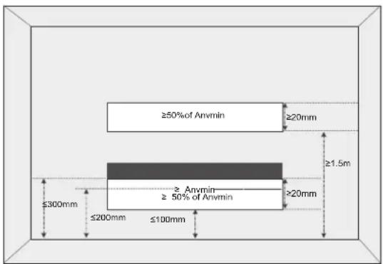
Figure 1-2
NOTE
- The requirement for the second opening can be met by drop ceilings, ventilation ducts, or similar arrangements that provide an airflow path between the connected rooms.
In addition, the maximum refrigerant charge is also related to the installation height of the indoor unit. And different values are used by different indoor unit installation heights:
- If installation height is greater than or equal to 1.8 m, but less than 2.2 m, use the refrigerant charge limitation of the graph for installation height 1.
- If installation height is not less than 2.2 m, use the refrigerant charge limitation of the graph for installation height 2.
NOTE
- The indoor unit installation height cannot be less than 1.8 m. For more detailed instructions on the installation height of the indoor units, please refer to the corresponding installation and operation manual.
- If the installation height of indoor unit is less than 1.8 m, please contact your installer or dealer to receive more information and professional advice.
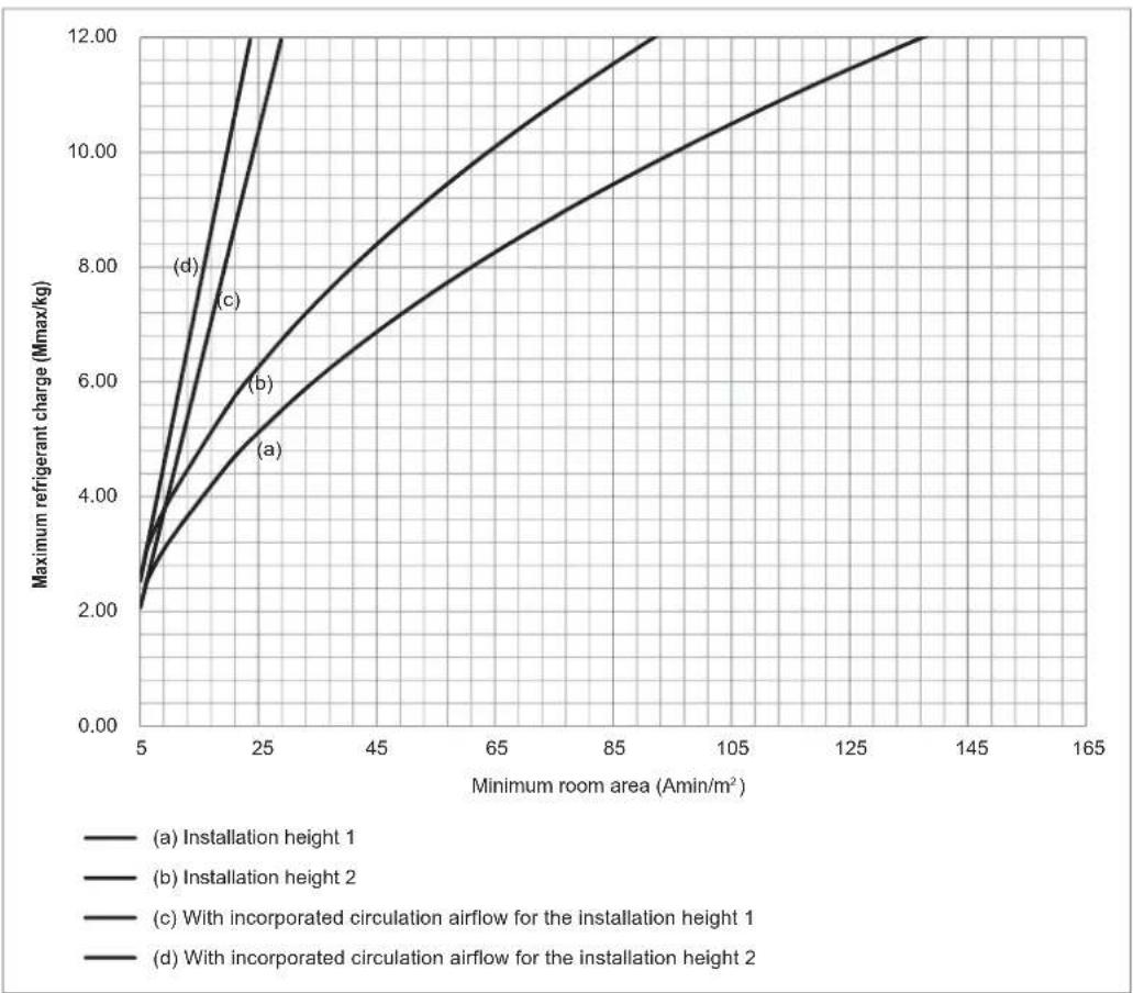
If no additional action is taken, the correspondence of the maximum refrigerant charge with the minimum room area (Amin) is shown in Figure 1-3 and Table 1-3.
1) Curve (a) is the refrigerant charge limitation for the indoor unit installation height between 1.8 m and 2.2 m without any conditions.
2) Curve (b) is the refrigerant charge limitation for the indoor unit installation height not less than 2.2 m without any conditions.
3) Curve (c) is the refrigerant charge limitation when the system meets the incorporated circulation airflow requirements for the indoor unit installation height between 1.8 m and 2.2 m.
4) Curve (d) is the refrigerant charge limitation when the system meets the incorporated circulation airflow requirements for the indoor unit installation height not less than 2.2 m.
NOTE
The maximum refrigerant charge of the curve (c) is available only if the following conditions are met:
- Minimum velocity of 1 m/s^2 , which is calculated as the indoor unit airflow divided by the nominal face area of the outlet. And the grill area shall not be deducted.
- Minimum airflow rate must meet the corresponding values in Table 1-2, which is related to the actual refrigerant charge of the system (Mc).
• R32 refrigerant leakage sensor is configured. - The room area applying the curve (c) or (d) shall satisfy all of the above requirements.
Table 1-2
| Mc/kg 1 2 3 | 4 | 5 6 7 | 8 | 9 10 | 11 12 | |||||
| Qv/m3/h | 98 195 293 | 391 | 489 586 684 | 782 | 879 977 1075 | 1173 |
line
| Minimum room area (Amin/m²) | (a) Installation height 1 | (b) Installation height 2 | (c) With incorporated circulation airflow for the installation height 1 | (d) With incorporated circulation airflow for the installation height 2 | | --------------------------- | ------------------------- | ------------------------- | ------------------------------------------------------------------ | ------------------------------------------------------------------ | | 5 | 2.00 | 2.00 | 2.00 | 2.00 | | 25 | 6.00 | 4.00 | 8.00 | 12.00 | | 100 | 10.00 | 8.00 | 12.00 | 12.00 |Figure 1-3
Table 1-3
| Amin/m2 | Mmax/kg--(a)/(b)/(c)/(d) Mmax/kg/(a)/(b)/(c)/(d) Mmax/kg--(a)/(b)/(c)/(d) | ||||
| 4 49 94 | 1.657/2.026/1.657/2.026 | 7.198/8.797/12/12 | 9.97/12/12/12 | ||
| 5 | 2.072/2.532/2.072/2.532 | 50 95 | 7.271/8.887/12/12 | 10.022/12/12/12 | |
| 6 | 2.486/3.039/2.486/3.039 | 51 96 | 7.343/8.975/12/12 | 10.075/12/12/12 | |
| 7 | 2.72/3.325/2.901/3.545 | 52 97 | 7.415/9.063/12/12 | 10.127/12/12/12 | |
| 8 | 2.908/3.554/3.315/4.052 | 53 98 | 7.486/9.15/12/12 | 10.18/12/12/12 | |
| 9 | 3.085/3.77/3.73/4.558 | 54 99 | 7.556/9.235/12/12 | 10.231/12/12/12 | |
| 10 | 3.251/3.974/4.144/5.065 | 55 100 | 7.626/9.321/12/12 | 10.283/12/12/12 | |
| 11 | 3.41/4.168/4.558/5.572 | 56 101 | 7.695/9.405/12/12 | 10.334/12/12/12 | |
| 12 | 3.562/4.353/4.973/6.078 | 57 102 | 7.763/9.489/12/12 | 10.385/12/12/12 | |
| 13 | 3.707/4.531/5.387/6.585 | 58 103 | 7.831/9.571/12/12 | 10.436/12/12/12 | |
| 14 | 3.847/4.702/5.802/7.091 | 59 104 | 7.898/9.654/12/12 | 10.487/12/12/12 | |
| 15 | 3.982/4.867/6.216/7.598 | 60 105 | 7.965/9.735/12/12 | 10.537/12/12/12 | |
| 16 | 4.113/5.027/6.631/8.104 | 61 106 | 8.031/9.816/12/12 | 10.587/12/12/12 | |
| 17 | 4.239/5.182/7.045/8.611 | 62 107 | 8.097/9.896/12/12 | 10.637/12/12/12 | |
| 18 | 4.362/5.332/7.46/9.117 | 63 108 | 8.162/9.975/12/12 | 10.686/12/12/12 | |
| 19 | 4.482/5.478/7.874/9.624 | 64 109 | 8.226/10.054/12/12 | 10.736/12/12/12 | |
| 20 | 4.598/5.62/8.289/10.131 | 65 110 | 8.29/10.133/12/12 | 10.785/12/12/12 | |
| 21 | 4.712/5.759/8.703/10.637 | 66 111 | 8.354/10.21/12/12 | 10.834/12/12/12 | |
| 22 | 4.823/5.895/9.117/11.144 | 67 112 | 8.417/10.287/12/12 | 10.882/12/12/12 | |
| 23 | 4.931/6.027/9.532/11.65 | 68 113 | 8.479/10.364/12/12 | 10.931/12/12/12 | |
| 24 | 5.037/6.157/9.946/12 | 69 114 | 8.542/10.44/12/12 | 10.979/12/12/12 | |
| 25 | 5.141/6.284/10.361/12 | 70 115 | 8.603/10.515/12/12 | 11.027/12/12/12 | |
| 26 | 5.243/6.408/10.775/12 | 71 116 | 8.664/10.59/12/12 | 11.075/12/12/12 | |
| 27 | 5.343/6.53/11.19/12 | 72 117 | 8.725/10.664/12/12 | 11.123/12/12/12 | |
| 28 | 5.441/6.65/11.604/12 | 73 118 | 8.786/10.738/12/12 | 11.17/12/12/12 | |
| 29 | 5.537/6.768/12/12 | 74 119 | 8.846/10.811/12/12 | 11.217/12/12/12 | |
| 30 | 5.632/6.884/12/12 | 75 120 | 8.905/10.884/12/12 | 11.264/12/12/12 | |
| 31 | 5.725/6.997/12/12 | 76 121 | 8.964/10.957/12/12 | 11.311/12/12/12 | |
| 32 | 5.817/7.109/12/12 | 77 122 | 9.023/11.028/12/12 | 11.358/12/12/12 | |
| 33 | 5.907/7.22/12/12 | 78 123 | 9.082/11.1/12/12 | 11.404/12/12/12 | |
| 34 | 5.996/7.328/12/12 | 79 124 | 9.14/11.171/12/12 | 11.451/12/12/12 | |
| 35 | 6.083/7.435/12/12 | 80 125 | 9.197/11.241/12/12 | 11.497/12/12/12 | |
| 36 | 6.17/7.541/12/12 | 81 126 | 9.255/11.311/12/12 | 11.543/12/12/12 | |
| 37 | 6.255/7.645/12/12 | 82 127 | 9.311/11.381/12/12 | 11.588/12/12/12 | |
| 38 | 6.339/7.747/12/12 | 83 128 | 9.368/11.45/12/12 | 11.634/12/12/12 | |
| 39 | 6.421/7.849/12/12 | 84 129 | 9.424/11.519/12/12 | 11.679/12/12/12 | |
| 40 | 6.503/7.949/12/12 | 85 130 | 9.48/11.587/12/12 | 11.724/12/12/12 | |
| 41 | 6.584/8.047/12/12 | 86 131 | 9.536/11.655/12/12 | 11.769/12/12/12 | |
| 42 | 6.664/8.145/12/12 | 87 132 | 9.591/11.723/12/12 | 11.814/12/12/12 | |
| 43 | 6.743/8.241/12/12 | 88 133 | 9.646/11.79/12/12 | 11.859/12/12/12 | |
| 44 | 6.821/8.337/12/12 | 89 134 | 9.701/11.857/12/12 | 11.903/12/12/12 | |
| 45 | 6.898/8.431/12/12 | 90 135 | 9.755/11.923/12/12 | 11.948/12/12/12 | |
| 46 | 6.974/8.524/12/12 | 91 136 | 9.809/11.989/12/12 | 11.992/12/12/12 | |
| 47 | 7.049/8.616/12/12 | 92 | 9.863/12/12/12 | ≥ 137 | 12/12/12/12 |
| 48 93 | 7.124/8.707/12/12 | 9.916/12/12/12 | |||
■ Condition B. With additional measure
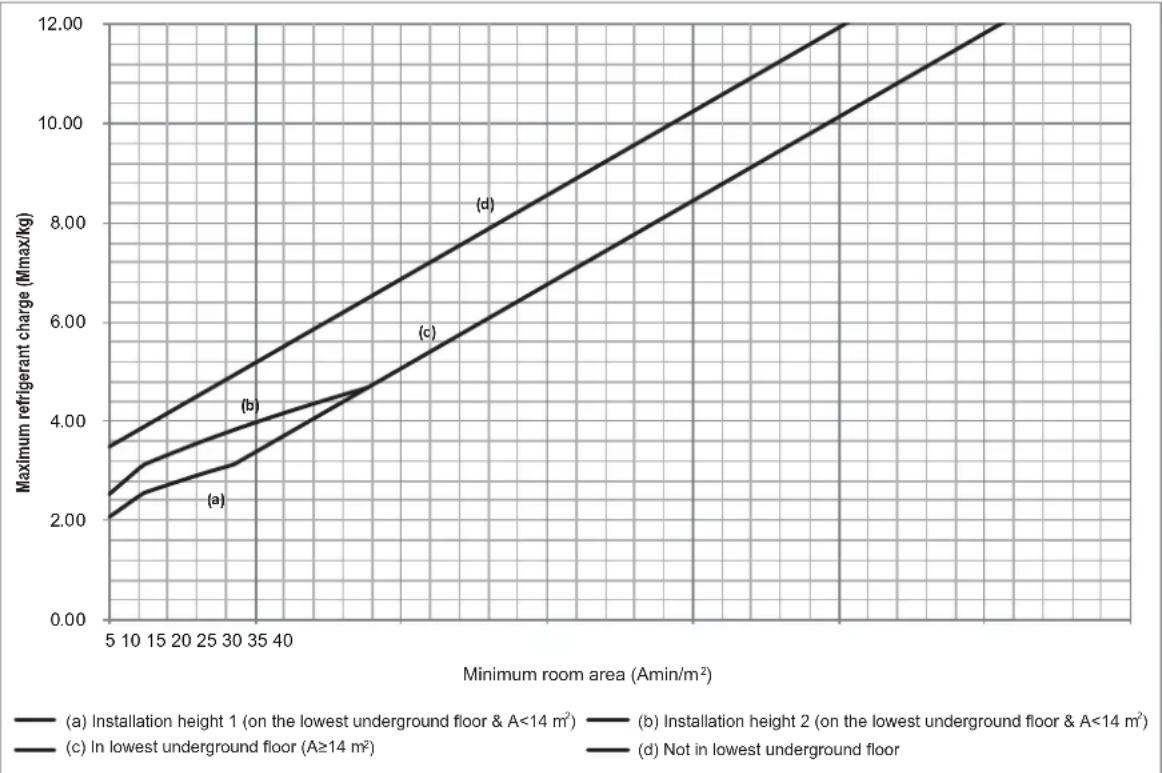
If the system is equipped with a factory refrigerant shut-off device on the outdoor unit main pipe and an alarm device connected to the indoor unit, further rules regarding refrigerant charge and room area can be followed. Figure 1-4 and Table 1-4 is suitable for 8-10 kW and Figure 1-5 and Table 1-5 is suitable for 12-18kW.
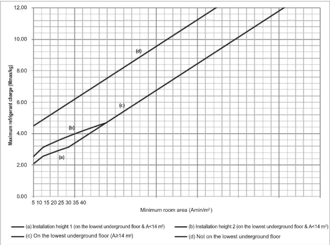
1) Curve (a) is the refrigerant charge limitation for the indoor unit installation height between 1.8 m and 2.2 m while A is < 14 m² on the lowest underground floor.
2) Curve (b) is the refrigerant charge limitation for the indoor unit installation height not less than 2.2 m while A is < 14 m² on the lowest underground floor.
3) Curve (c) is the refrigerant charge limitation for the smallest room on the lowest underground floor while A is ≥ 14 m^2 .
4) Curve (d) is the refrigerant charge limitation for the smallest room not on the lowest underground floor.
NOTE
- Only the factory refrigerant shut-off device can be used.
- The refrigerant shut-off device shall be located outside.
- The refrigerant shut-off device shall only be installed on the main pipe and is close to the first branch joint.
- The refrigerant shut-off device is not allowed for series or parallel connections.
- The refrigerant shut-off device shall be positioned to enable access for maintenance by an authorized person.
NOTE
- The alarm device shall be turned on by the signal from the refrigerant leakage sensor.
- The alarm device shall also alert an authorized person to take appropriate action.
- The alarm device shall provide both audible and visual warnings, such as by a loud (15 dBA above the background noise level) buzzer and a flashing light.
- At least one alarm device shall be installed inside each occupied space. For the occupancy listed below, the alarm system shall also warn at a supervised location, such as the night porter's location, as well as the occupied space.
Rooms, parts of buildings, buildings where
• sleeping facilities are provided,
• people are restricted in their movement, - an uncontrolled number of people are present, or
• to which any person has access without being personally acquainted with the necessary safety precautions.
- In cases where the alarm device is installed, the power source of the alarm system shall be from a power source independent of the refrigerating systems which the alarm system is protecting.
For 8-10 kW
line
| Minimum room area (Amin/m²) | Maximum refrigerant charge (Mmax/kg) - (a) Installation height 1 (on the lowest underground floor & A<14 m²) | Maximum refrigerant charge (Mmax/kg) - (b) Installation height 2 (on the lowest underground floor & A<14 m²) | Maximum refrigerant charge (Mmax/kg) - (c) In lowest underground floor (A≥14 m²) | Maximum refrigerant charge (Mmax/kg) - (d) Not in lowest underground floor | | --------------------------- | ------------------------------------------------------------------------------------------ | ------------------------------------------------------------------------------------------ | ------------------------------------------------------------------ | ------------------------------------------------------------------ | | 5 | 3.5 | 3.0 | 2.5 | 2.0 | | 10 | 3.8 | 3.3 | 2.8 | 2.3 | | 15 | 4.0 | 3.6 | 3.0 | 2.5 | | 20 | 4.2 | 3.9 | 3.2 | 2.7 | | 25 | 4.5 | 4.2 | 3.5 | 3.0 | | 30 | 4.8 | 4.5 | 3.8 | 3.3 | | 35 | 5.0 | 4.8 | 4.0 | 3.5 | | 40 | 5.2 | 5.0 | 4.2 | 3.7 | | 45 | 5.5 | 5.3 | 4.5 | 4.0 | | 50 | 5.8 | 5.6 | 4.8 | 4.3 | | 55 | 6.0 | 5.9 | 5.0 | 4.5 | | 60 | 6.2 | 6.1 | 5.2 | 4.7 | | 65 | 6.5 | 6.4 | 5.5 | 4.9 | | 70 | 6.8 | 6.7 | 5.8 | 5.1 | | 75 | 7.0 | 7.0 | 6.0 | 5.3 | | 80 | 7.2 | 7.2 | 6.2 | 5.5 | | 85 | 7.5 | 7.5 | 6.5 | 5.7 | | 90 | 7.8 | 7.8 | 6.8 | 5.9 | | 95 | 8.0 | 8.0 | 7.0 | 6.1 | | 100 | 8.2 | 8.2 | 7.2 | 6.3 | | 105 | 8.5 | 8.5 | 7.5 | 6.5 | | 110 | 8.8 | 8.8 | 7.8 | 6.7 | | 115 | 9.0 | 9.0 | 8.0 | 6.9 | | 120 | 9.2 | 9.2 | 8.2 | 7.1 | | 125 | 9.5 | 9.5 | 8.5 | 7.3 | | 130 | 9.8 | 9.8 | 8.8 | 7.5 | | 135 | 10.0 | 10.0 | 9.0 | 7.7 | | 140 | 10.2 | 10.2 | 9.2 | 7.9 | | 145 | 10.5 | 10.5 | 9.5 | 8.1 | | 150 | 10.8 | 10.8 | 9.8 | 8.3 | | 155 | 11.0 | 11.0 | 10.0 | 8.5 | | 160 | 11.2 | 11.2 | 10.2 | 8.7 | | 165 | 11.5 | 11.5 | 10.5 | 8.9 | | 170 | 11.8 | 11.8 | 10.8 | 9.1 | | 175 | 12.0 | 12.0 | 11.0 | 9.3 | | Note: The data is already in CSV format with three columns: first column contains 'Minimum room area' values from the minimum floor of each room area, and second column contains 'Maximum refrigerator charge' values for each room area under each ceiling width range (A=≤A<14 m²). There are three additional lines representing different installation heights and ground floor requirements.Figure 1-4
For 12-18 kW (Single-phase & three-phase)
line
| Minimum room area (Amin/m²) | (a) Installation height 1 (on the lowest underground floor & A<14 m²) | (b) Installation height 2 (on the lowest underground floor & A<14 m²) | (c) On the lowest underground floor (A≥14 m²) | (d) Not on the lowest underground floor | | --------------------------- | ------------------------------------------------------------------ | ------------------------------------------------------------------ | ------------------------------------------ | -------------------------------------- | | 5 | 2.00 | 2.50 | 3.00 | 4.50 | | 10 | 2.50 | 3.00 | 3.50 | 5.00 | | 15 | 3.00 | 3.50 | 4.00 | 5.50 | | 20 | 3.50 | 4.00 | 4.50 | 6.00 | | 25 | 4.00 | 4.50 | 5.00 | 6.50 | | 30 | 4.50 | 5.00 | 5.50 | 7.00 | | 35 | 5.00 | 5.50 | 6.00 | 7.50 | | 40 | 5.50 | 6.00 | 6.50 | 8.00 | | 45 | 6.00 | 6.50 | 7.00 | 8.50 | | 50 | 6.50 | 7.00 | 7.50 | 9.00 | | 55 | 7.00 | 7.50 | 8.00 | 9.50 | | 60 | 7.50 | 8.00 | 8.50 | 10.00 | | 65 | 8.00 | 8.50 | 9.00 | 10.50 | | 70 | 8.50 | 9.00 | 9.50 | 11.00 | | 75 | 9.00 | 9.50 | 10.00 | 11.50 | | 80 | 9.50 | 10.00 | 10.50 | 12.00 | | 85 | 10.00 | 10.50 | 11.00 | | | 90 | 10.50 | 11.00 | | | | 95 | 11.00 | | | | | 100 | | | | |Figure 1-5
For 8-10 kW
Table 1-4
| Amin/m2 | Mmax/kg--(a)/(b)/(c)/(d) | Mmax/kg-(a)/(b)/(c)/(d) | Amin/m2 | Mmax/kg--(a)/(b)/(c)/(d) | |
| 4 15 26 | 1.657/2.026/-/3.15 | -/-/5.065/6.865 | -/-/8.78/10.58 | ||
| 5 16 27 | 2.072/2.532/-/3.488 | -/-/5.403/7.203 | -/-/9.117/10.917 | ||
| 6 17 28 | 2.486/3.039/-/3.826 | -/-/5.74/7.54 | -/-/9.455/11.255 | ||
| 7 18 29 | 2.72/3.325/-/4.163 | -/-/6.078/7.878 | -/-/9.793/11.593 | ||
| 8 19 30 | 2.908/3.554/-/4.501 | -/-/6.416/8.216 | -/-/10.131/11.931 | ||
| 9 20 31 | 3.085/3.77/-/4.839 | -/-/6.754/8.554 | -/-/10.468/12 | ||
| 10 21 32 | 3.377/3.974/-/5.177 | -/-/7.091/8.891 | -/-/10.806/12 | ||
| 11 22 33 | 3.714/4.168/-/5.514 | -/-/7.429/9.229 | -/-/11.144/12 | ||
| 12 23 34 | 4.052/4.353/-/5.852 | -/-/7.767/9.567 | -/-/11.481/12 | ||
| 13 24 35 | 4.39/4.531/-/6.19 | -/-/8.104/9.904 | -/-/11.819/12 | ||
| -/-/4.727/6.527 | -/-/8.442/10.242 | ≥3614 25 | -/-/12/12 | ||
| (a): The IDU installation height is between 1.8 m and 2.2 m while A is <14 m2 and on the lowest underground floor (b): The IDU installation height is not less than 2.2 m while A is <14 m2 and on the lowest underground floor (c): The refrigerant charge limitation is on the lowest underground floor while A is ≥14 m2.(d): The refrigerant charge limitation is not on the lowest underground floor. | |||||
For 12-18 kW (Single-phase & three-phase)
Table1-5
| Amin/m2 | Mmax/kg-(a)/(b)/(c)/(d) | Mmax/kg-(a)/(b)/(c)/(d) | Mmax/kg-(a)/(b)/(c)/(d) | Adin/m2 | |
| 4 15 26 | 2.657/2.026/-/4.15 | -/-/5.065/7.865 | -/-/8.78/11.58 | ||
| 5 16 27 | 2.072/2.532/-/4.488 | -/-/5.403/8.203 | -/-/9.117/11.917 | ||
| 6 17 28 | 2.486/3.039/-/4.826 | -/-/5.74/8.54 | -/-/9.455/12 | ||
| 7 18 29 | 2.72/3.325/-/5.163 | -/-/6.078/8.878 | -/-/9.793/12 | ||
| 8 19 30 | 2.908/3.554/-/5.501 | -/-/6.416/9.216 | -/-/10.131/12 | ||
| 9 20 31 | 3.085/3.77/-/5.839 | -/-/6.754/9.554 | -/-/10.468/12 | ||
| 10 21 32 | 3.377/3.974/-/6.177 | -/-/7.091/9.891 | -/-/10.806/12 | ||
| 11 22 33 | 3.714/4.168/-/6.514 | - /-/7.429/10.229 | -/-/11.144/12 | ||
| 12 23 34 | 4.052/4.353/-/6.852 | -/-/7.767/10.567 | -/-/11.481/12 | ||
| 13 24 35 | 4.39/4.531/-/7.19 | -/-/8.104/10.904 | -/-/11.819/12 | ||
| 14 25 | -/-/4.727/7.527 | -/-/8.442/11.242 | ≥36 | -/-/12/12 |
(a): The IDU installation height is between 1.8 m and 2.2 m while A is <14m^2 and on the lowest underground floor
(b): The IDU installation height is not less than 2.2 m while A is <14m² and on the lowest underground floor
(c): The refrigerant charge limitation is on the lowest underground floor while A is ≥14m^2 .
(d): The refrigerant charge limitation is not on the lowest underground floor.

NOTE
- The maximum refrigerant charge has to be assessed for the room with the smallest room area in both the lowest underground floor and the other floors.
- And in the lowest underground floor, the maximum refrigerant charge is also related to types of the indoor units, which have different installation heights.
- The lowest maximum allowable charge of all shall be used.

NOTE
- If the unit is connected via an air duct system to multiple rooms, the applicable maximum refrigerant limits are different. Please contact your installer or dealer for further information and professional advice.

NOTE
- The maximum refrigerant limit described above applies to unventilated areas. If adding additional measures, such as areas with mechanical ventilation, please refer to applicable legislation for the maximum refrigerant limit.

CAUTION
- The application also has a maximum design refrigerant charge limit of 12 kg, which cannot be exceeded in any circumstances.
- If the system applies to case (d) in Figure 1-4 and Table 1-4 or Figure 1-5 and Table 1-5, the minimum room area for a 8-10 kW outdoor unit must not be less than 7 m ^2 and the minimum room area for a 12-18 kW outdoor unit must not be less than 10 m ^2 .
Determine the charge limit for the refrigerating system as the smaller of:
1) The maximum refrigerant charge (Mmax) in the system from the above room area limitations.
2) The maximum refrigerant charge (Mmax) with air duct system or additional measures, such as areas with mechanical ventilation.
3) 12 kg from the limit of the application.

CAUTION
- The refrigerant leakage sensor can only use the factory model or the specified model indicated in the corresponding manual.
- The R32 refrigerant leakage sensor must be used to activate the refrigerant shut-off device, the alarm device, incorporated circulation airflow or other emergency controls, which shall give an electrical signal at a predetermined alarm set point in response to leaked refrigerant.
- The location of leakage sensors shall be chosen in relation to the refrigerant and they shall be located where leaked refrigerant will concentrate. Please refer to the indoor unit installation manual for specific requirements.
- The installation of the refrigerant leakage sensor shall allow access for checking, repair or replacement by an authorized person.
- The refrigerant leakage sensor shall be installed so its function can be verified easily.
- The refrigerant leakage sensor shall be protected to prevent tampering or unauthorized resetting of the pre-set value.
- To be effective, the refrigerant leakage sensor must be electrically powered at all times after installation, other than when servicing.
■ Installation scheme flow chart
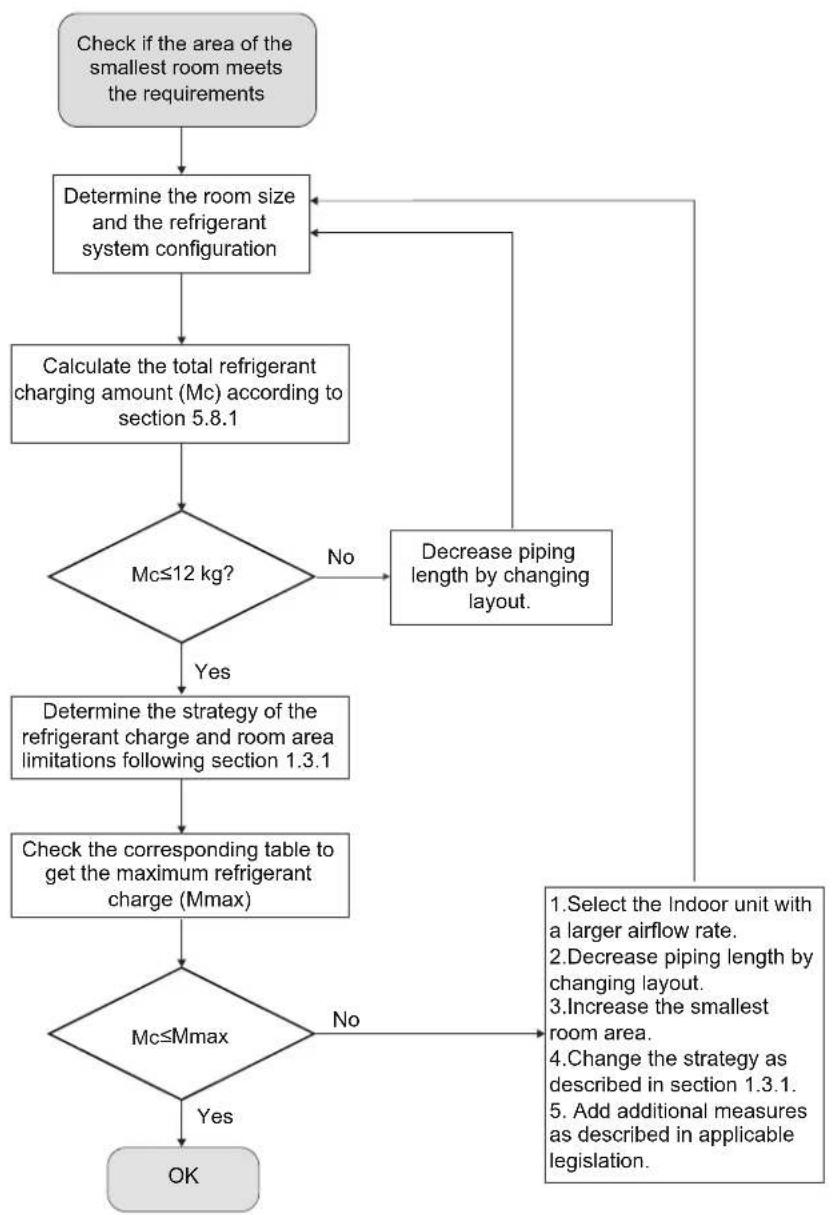
flowchart
graph TD
    A["Check if the area of the smallest room meets the requirements"] --> B["Determine the room size and the refrigerant system configuration"]
    B --> C["Calculate the total refrigerant charging amount (Mc) according to section 5.8.1"]
    C --> D{Mc≤12 kg?}
    D -->|No| E["Decrease piping length by changing layout."]
    D -->|Yes| F["Determine the strategy of the refrigerant charge and room area limitations following section 1.3.1"]
    F --> G["Check the corresponding table to get the maximum refrigerant charge (Mmax)"]
    G --> H{Mc≤Mmax}
    H -->|No| I["Select the Indoor unit with a larger airflow rate."]
    H -->|Yes| J["OK"]
    I --> K["Decrease piping length by changing layout."]
    K --> B
    L["Increase the smallest room area."] --> M["Change the strategy as described in section 1.3.1."]
    M --> N["Add additional measures as described in applicable legislation."]
2. OPERATIONS
2.1 Operating Range
Use the system in the following temperatures to ensure safe and effective operation. The Operating range for the air conditioner is shown in Table 2-1.
Table 2-1
| Model | 8/10/12/14/16/18 kW | |
| Cooling | Outdoor temperature /DB | -15 °C to 52 °C |
| Indoor temperature /DB | 16 °C to 30 °C | |
| Indoor temperature /WB | 13 °C to 23 °C | |
| Heating | Outdoor temperature /DB | -20 °C to 30 °C |
| Outdoor temperature /WB | -20 °C to 16.5 °C | |
| Indoor temperature /DB | 16 °C to 30 °C | |
| Dehumidification | Outdoor temperature /DB | -15 °C to 52 °C |
| Indoor temperature /DB | 12 °C to 30 °C | |
| Indoor temperature /WB | 9 °C to 23 °C | |
NOTE
- If the above operating conditions cannot be met, the safety protection function may be triggered and the air conditioner may malfunction.
- When the unit operates in "cooling" mode in a relatively humid environment (relative humidity higher than 80%), condensation may occur on the surface of the IDU and water may drip. In this case, turn the wind deflector to the maximum air outlet position and set the fan speed to "High".
- Outdoor operating temperature under -5 °C in "cooling" mode, the startup capacity of IDUs must meet at least 30% of ODU capacity.
2.2 Operation and Performance
2.2.1 Operating System
Run
Press the "switch" button on the controller. Result: The running light turns on and the system starts to run.
Repeatedly press the mode selector on the controller to select the required operation mode.
Stop
Press the "switch" button on the controller again. Result: The running light is now off, and the system stops running.
Adjust
Refer to the controller user manual for information about how to set the required temperature, fan speed and air flow direction.
NOTE
- To protect this unit, please turn on the main power supply 12 hours before you start to operate this unit.
- Once the unit has stopped running, do not disconnect the power immediately. Wait for at least 10 minutes.
2.2.2 Cooling and heating operations
The indoor units in the air conditioner can be controlled separately, but the indoor units in the same system cannot operate in the heating and cooling modes at the same time.
When the cooling and heating operation conflict with each other, the indoor units which are running in cooling or fan mode will stop and will display the message standby or no priority on the control panel. Those indoor units which are running on heating mode will run continuously.
If the air conditioner administrator has set the running mode, then the air conditioner cannot run in any mode other than the mode presented. Standby or no priority will be displayed on the control panel.
2.2.3 Features of heating operation
About heating capacity
Once the unit starts, it takes some time for the room temperature to rise, as the unit uses a hot air circulation system to heat the room.
The indoor fan motor will automatically stop running so as to prevent cold air from coming out of the indoor unit when the heating operation starts. This process will take some time, which depends on the indoor and outdoor temperature. This is not a malfunction.
When there is a drop in the external temperature, the heating capacity decreases. If this happens, please use other heating equipment and units at the same time. (Make sure the room is well ventilated if you are using equipment that produces fire.) Do not place any equipment that may produce a fire where the air outlets of the unit are or below the unit itself.
And need to perform the following operations to prevent the heating capacity from dropping or prevent cold air from coming out of the system.
Defrost operation
While heating, as the outdoor temperature decreases, frost may form on the heat exchanger in the outdoor unit, making it more difficult for the heat exchanger to heat up the air. The heating capacity will decrease, and the system will need to be defrosted in order to provide sufficient heat to the indoor unit. At this point, the control panel of the indoor unit will show that a defrost operation is occurring.
NOTE
- The motor in indoor unit will continue running for about 40 seconds to remove residual heat when the indoor unit receives a shutdown command while heating.
- If the air conditioner malfunction occurs because of interferences, please disconnect the power from the air conditioner, then turn it on again.
2.2.4 Power cuts
If there is a power outage while the unit is running, the unit will automatically restart its operation when the power supply resumes.
Mishandling in operation
If mishandling happens, please disconnect the power from the system and then reconnect it after a few minutes.
2.2.5 Protective feature
A protection feature prevents the air conditioner from being activated for 3\~7 minutes when it restarts immediately after operation.
2.2.6 Protective equipment
This protective equipment will enable the air conditioner to stop when the air conditioner is forced to run.
The protective equipment may be activated in the following circumstances:
Cooling
- The air inlet or air outlet of the outdoor unit is blocked.
• Strong wind is Continuously blowing into the air outlet of the outdoor unit.
Heating
- Too much dust and rubbish are stuck to the dust filter of the indoor unit.
• The air outlet of indoor unit is choked.
NOTE
- When the protective equipment activates, please shut down the manual power breaker, and restart operations after the problem is solved.
3. MAINTENANCE AND REPAIR
Each refrigerating system shall be subjected to preventive maintenance in accordance with legal requirements. The frequency of maintenance depends on the type, size, age, use, etc. of the system. In many cases, more than one maintenance service is required in one year.
The operator of the refrigerating system shall ensure that the system is inspected, regularly supervised and maintained.
Systems should be inspected for tightness by a qualified person. If, during the inspection, it is suspected that there is a leak, e.g. through refrigerant temperature checks or capacity reduction, then the location of the leak shall be identified with suitable detection equipment and shall be repaired and checked again after the repair in accordance with national regulations. The results of the inspection and measures taken afterwards shall be included in the logbook.
Regular leak tests and inspections shall be carried out including checking of the safety equipment.
WARNING
- When recycling refrigerant, you must select the menu to enter the vacuum mode to ensure that the refrigerant is thoroughly recovered.
- If the system is configured with a refrigerant shut-off device, the refrigerant needs to be recovered from the maintenance needle valves of the ODU check valves and the refrigerant shut-off device respectively. In addition, recycling refrigerant only from the ODU check valves is also allowed when the system is powered on and the ODU is without any error code of Ad1, C21, C26, C28, C2A and EC1.
- When the breaker was broken, do not use any unspecified breaker or other wire to replace the original breaker. The use of electrical wires or copper wires may cause the unit to malfunction or cause a fire.
- Do not insert your fingers, sticks, or other items into the air inlet or outlet. Do not remove the fan mesh cover. When the fan rotates at a high speed, it could cause bodily injury.
- It is very dangerous to check the unit when the fan is rotating.
- Make sure you turn off the main breaker before any maintenance work begins.
- Check the supporting and base structure of the unit for any damages after a long period of use. The unit could fall and cause personal injury if there is any damage.
NOTE
- Do not check or repair the unit on your own. Please get qualified professionals to conduct any checks or repairs.
- Do not use substances like gasoline, diluent, or chemical dust cloths to wipe the operations panel of the controller. Doing so could remove the surface layer of the controller. If the unit is dirty, immerse a cloth in diluted and neutral detergent, wring it out, and then use it to clean the panel. Lastly, wipe it with a dry cloth.
- Ensure that the area is in the open or that it is adequately ventilated before opening the system or conducting any hot work. A degree of ventilation shall continue during the period that the work is carried out. The ventilation should safely disperse any released refrigerant and preferably expel it externally into the surroundings.
3.1 Maintenance After the Unit Has Been Shut Down for a Long Period
For example, in early summer or winter.
- Check and remove all objects that may clog the air inlets and outlets of the indoor and outdoor units.
- Clean the air filter and external shell of the unit. Please contact the installation or maintenance personnel. The installation/operation manual of the indoor unit includes maintenance tips and cleaning procedures. Make sure that the clean air filter is installed in its original position. Check and remove all objects that may clog the air inlets and outlets of the indoor and outdoor units.
- Turn on the main power supply 12 hours before the unit is operated in order to ensure that the unit runs smoothly. The user interface will be displayed once the power is turned on.
For example, at the end of winter or summer.
- Run the indoor unit in the fan mode for about half a day to dry the internal parts of the unit.
• Turn off the power supply. - Clean the air filter and external shell of the unit. Please contact the installation or maintenance personnel to clean the air filter and external shell of the indoor unit. The installation/operation manual of the specialized indoor unit includes maintenance tips and cleaning procedures. Make sure that the clean air filter is installed in its original position.
3.2 About the Refrigerant
This product contains fluorinated greenhouse gases as stipulated in the Kyoto Protocol. Do not discharge the gas into the atmosphere.
Refrigerant Type: R32
GWP Value: 675
Based on applicable laws, the refrigerant must be checked regularly for leakages. Please contact the installation personnel for more information.
WARNING
- The refrigerant in the air conditioner is relatively safe, and usually does not leak. If the refrigerant leaks and comes in contact with an open flame, it will produce harmful gases.
- Shut down any heating devices which use flames, ventilate the room and contact the agent of the unit immediately.
- Do not use the air conditioner again until the maintenance personnel has confirmed that the refrigerant leakage has been completely resolved.
3.3 After-sales Service and Warranty
3.3.1 Warranty period
This product contains the warranty card that was completed by the agent during installation. The customer must check the completed warranty card and retain it properly.
If you need to repair the air conditioner during the warranty period, please contact the agent and provide the warranty card.
When you request assistance from the agent, please remember to state:
• The complete model name of the air conditioner.
- Date of installation.
• Details on the fault symptoms or errors, and any defects.
WARNING
- Do not attempt to modify, dismantle, remove, reinstall or repair this unit, as the improper dismantling or installation of the unit may result in electric shock or fire. Please contact an agent.
- If the refrigerant accidentally leaks, make sure that there are no open flames around the unit. The refrigerant itself is completely safe, non-toxic and non-flammable, but it will produce toxic gases when it accidentally leaks and comes into contact with flammable substances generated by existing heaters, and burning devices in the room. Qualified maintenance personnel must verify that the point of leakage has been repaired or rectified before you resume operations of the unit.
3.4 Shorter Maintenance and Replacement Cycle
- Temperature and humidity fluctuations are outside the normal ranges.
- Large power fluctuations (voltage, frequency, waveform distortion etc.) (must not use the unit if the power fluctuations exceed the allowed range).
• Frequent collisions and vibrations. - The air may contain dust, salt, harmful gases or oils such as sulphite and hydrogen sulphide.
- Frequently turning the unit on and off or operating the unit for too long (in places where the air conditioning is on for 24 hours a day).
4. TROUBLESHOOTING
4.1 Air Conditioner Troubles and Their Causes
If one of the following malfunctions occurs, stop the air conditioner from operating, shut off the power, and contact your dealer.
- The remote controller malfunctions or the buttons do not work well.
• A safety device such as a leakage breaker or a circuit breaker is frequently tripped.
• Dust, moisture and other particles enter the unit.
• Water leaks from the indoor unit.
• Other malfunctions.
If the system does not properly operate, excluding in the above mentioned cases or if the above mentioned malfunctions are evident, use the following procedures to check the system. (See Table 4-1)
Table 4 -1
| Symptoms | Causes | Solution |
| Unit does not start | Power failure.Power breaker is off.Batteries of the remote controller are exhausted or another problem with the controller. | Wait for the power to return.Switch on the power.Replace the batteries or check the controller. |
| Air is flowing normally but completely does not cool | Temperature is not set correctly.The unit's compressor is in the 3-7 minute protection period. | Set the temperature properly.Wait. |
| Units start or stop frequently | Refrigerant is too little or too much.There is air or no concreting gas in the refrigerating circuit.The compressor is malfunctioning.Voltage is too high or too low.The system circuit is blocked. | Check leakage, and correctly recharge the refrigerant.Vacuum and recharge refrigerant.Maintain or change compressor.Install a manostat.Find reasons and solutions. |
| Poor cooling effect | Outdoor unit and indoor unit heat exchanger is dirty.The air filter is dirty.Inlet/outlet of indoor/outdoor units is blocked.Doors and windows are openSunlight is shining directly on the unit.There are too many heat resources.Outdoor temp. is too high.Leakage of refrigerant or lack of refrigerant. | Clean the heat exchanger.Clean the air filter.Eliminate all dirt and allow air to flow smoothly.Close doors and windows.Install or close curtains in order to shade the unit from sunshine.Reduce heat source.AC cooling capacity is reduced (normal)Check for leakage and correctly recharge refrigerant. |
| Poor heating effect | Outdoor temperature is lower than 7 ^ Doors and windows are not completely closed.Leakage of refrigerant or lack of refrigerant. | Use heating devices.Close doors and windows.Check for leakage and correctly recharge refrigerant. |
4.2 Troubles and Causes of Remote Controller
Before requesting service or repair, check the following points.
(see Table 4-2)
Table 4 -2
| Symptoms | Causes | Solution |
| The fan speed cannot be changed. | Check whether the MODE indicated on the display is "AUTO". | When the automatic mode is selected, the air conditioner will automatically change its fan speed. |
| Check whether the MODE indicated on the display is "DRY". | When dry operation is selected, the air conditioner automatically changes the fan speed. The fan speed can be selected in "COOL", "FAN ONLY", and "HEAT" modes | |
| The remote controller signal is not transmitted even when the ON/OFF button is pushed. | Check whether the batteries in the remote controller are exhausted. | The power supply is off. |
| The TEMP. indicator does not come on. | Check whether the MODE indicated on the display is FAN ONLY. | The temperature cannot be set during FAN mode. |
| The indication on the display disappears after a lapse of time. | Check whether the timer operation has come to an end when the TIMER OFF is indicated on the display. | The air conditioner operation will stop when reaching the set time. |
| The TIMER ON indicator goes off after a lapse of certain time. | Check whether the timer starts when the TIMER ON is indicated on the display. | When the set time is reached, the air conditioner will automatically start and the appropriate indicator will go off. |
| The indoor unit does not produce a sound when the ON/OFF button is pressed. | Check whether the signal transmitter of the remote controller is properly directed to the infrared signal receiver of the indoor unit when the ON/OFF button is pressed. | The air conditioner operation will stop when it reaches the set time. |
4.3 Error Code: Overview
If an error code appears on the controller, please contact the installation personnel and inform them of the error code, device model, and serial number (you can find the information on the nameplate of the unit).
Table 4-3 Outdoor unit error code
| Error descriptionError code | Manual re-start required | |
| A01 | Emergency stop | NO |
| A11 | Indoor unit refrigerant leakage | YES |
| AA1 | Inverter driver chip and main control chip mismatch | NO |
| Ad1 | Refrigerant shut-off device error | NO |
| C21 | Communication error between indoor and outdoor unit | NO |
| C26 | Number of indoor units detected by the outdoor unit has decreased | NO |
| C28 | Number of indoor units detected by the outdoor unit has increased | NO |
| C2A | Communication error between outdoor unit and refrigerant shut-off device | NO |
| 1C41 | Communication error between main control chip and inverter driver chip | NO |
| E41 | Outdoor ambient temperature sensor (T4) error (open/short) | NO |
| EC1 | Refrigerant leakage sensor error | NO |
| F31 | Plate heat exchanger outlet temperature sensor (T6B) error (open/short) | NO |
| F41 | Outdoor heat exchanger temperature sensor (T3) error (open/short) | NO |
| F62 | Inverter module temperature (Tf) protection | NO |
| F63 | Non-inductance resistor temperature (Tr) protection | NO |
| F6A | F62 protection occurs 3 times in 100 minutes | YES |
| F71 | Discharge temperature sensor (T7C) error (open/short) | YES |
| F72 | Discharge temperature (T7C) protection | NO |
| F75 | Compressor discharge insufficient superheat protection | NO |
| F7A | F72 protection occurs 3 times in 100 minutes | YES |
| F91 | Liquid pipe temperature sensor (T5) error (open/short) | NO |
| FA1 | Outdoor heat exchanger inlet temperature sensor (T8) error (open/short) | NO |
| FC1 | Outdoor heat exchanger outlet temperature sensor (TL) error (open/short) | NO |
| Fd1 | Compressor suction temperature sensor (T7) error (open/short) | NO |
| 1L-- | Compressor error. Refer to Table 4-5 for indications of “--” | YES |
| 1L01 | 1L1* error occurs 3 times in 60 minutes. Refer to Table 4-5 for indications of “*” | YES |
| 1J-- | Fan motor error. Refer to Table 4-6 for indications of “--” | YES |
| 1J01 | 1J1* error occurs 10 times in 60 minutes. Refer to Table 4-6 for indications of “*” | YES |
| P11 | High pressure sensor error | NO |
| P12 | Discharge pipe high pressure protection | NO |
| P13 | Discharge pipe high pressure switch protection | NO |
| P21 | Low pressure sensor error | YES |
| P22 | Suction pipe low pressure protection | NO |
| P24 | Suction pipe low pressure abnormal rise | NO |
| P25 | P22 error occurs 3 times in 100 minutes | YES |
| 1P32 | Compressor high DC bus current protection | NO |
| 1P33 | 1P32 protection occurs 3 times in 100 minutes | YES |
| P51 | High AC voltage protection | NO |
| P52 | Low AC voltage protection | NO |
| P53 | Power supply BN connect protection, or the phase is missing, or unbalanced when powered on | YES |
| P54 | DC bus low voltage protection | NO |
| P55 | DC bus ripple wave protection, or the phase is missing, or unbalanced when powered on | YES |
| 1P56 | Inverter module DC bus low voltage error | YES |
| 1P57 | Inverter module DC bus high voltage error | YES |
| 1P58 | Inverter module DC bus seriously high voltage error | YES |
| 1P59 | Inverter module busbar voltage drop protection | YES |
| P71 | EEPROM error | YES |
| P91 | PFC feedback resistance failure protection | YES |
| Pb1 | HyperLink overcurrent error | NO |
| 1b01 | Electronic expansion valve (EEVA) error | YES |
| 3b01 | Electronic expansion valve (EEVC) error | YES |
Table 4-4 Installation and debugging error code
| Error descriptionError code | Manual re-start required | |
| NOTechnology barrierU02 | ||
| U11 | Unit type is not set | YES |
| U12 | Capacity setting error | YES |
| U21 | Indoor unit with old platform in the system | YES |
| U31 | The test run is not performed or was not successful | YES |
| U32 | Outdoor temperature out of operating range | YES |
| U33 | Indoor temperature out of operating range | YES |
| U34 | Outdoor and indoor temperature out of operating range | YES |
| U35 | Liquid side stop valve is not opened | YES |
| U37 | Gas side stop valve is not opened | YES |
| U38 | No address | YES |
| U3A | The communication cable is connected incorrectly | NO |
| U3b | The installation environment is abnormal | YES |
| U3C | Auto mode error | NO |
| U41 | Common indoor unit exceeds the allowable connection range | YES |
Table 4-5 Compressor driver error code
| Error descriptionError code | Manual re-start required | |
| 1L1E | Hardware overcurrent | NO |
| 1L11 | Software overcurrent | NO |
| 1L12 | Software overcurrent protection last 30s | NO |
| 1L2E | Inverter module high temperature protection | NO |
| 1L3E | Low bus voltage error | NO |
| 1L31 | High bus voltage error | NO |
| 1L32 | Serious over voltage error of bus | NO |
| 1L43 | Abnormal current sampling | NO |
| 1L45 | Motor code mismatch | YES |
| 1L46 | IPM protection | NO |
| 1L47 | Module type mismatch | YES |
| 1L5E | Startup failed | NO |
| 1L51 | Stall failure | NO |
| 1L52 | No load protection | NO |
| 1L6E | Motor phase loss protection | NO |
| 1LbE | High voltage switch action | NO |
| 1Lb7 | Other check exceptions/908 diagnosis error | NO |
Table 4-6 Fan motor error code
| Error descriptionError code | Manual re-start required | |
| 1J1E | Hardware overcurrent | NO |
| 1J11 | Software overcurrent | NO |
| 1J12 | Software overcurrent protection in last 30s | NO |
| 1J2E | Inverter module high temperature protection | NO |
| 1J3E | Low bus voltage error | NO |
| 1J31 | High bus voltage error | NO |
| 1J32 | Serious over voltage error of bus | NO |
| 1J43 | Abnormal current sampling | NO |
| 1J45 | Motor code mismatch | YES |
| 1J46 | IPM protection | NO |
| 1J47 | Module type mismatch | YES |
| 1J5E | Startup failed | NO |
| 1J51 | Stall failure | NO |
| 1J52 | No load protection | NO |
| 1J6E | Motor phase loss protection | NO |
Table 4-7 Status code
| Code descriptionStatus code | Manual re-start required | |
| d0x | Oil return running, x represents oil return operation steps | NO |
| dfx | Defrost running, x represents defrosting operation steps | NO |
| d11 | Outdoor ambient temperature exceeds the upper limit in Heating mode | NO |
| d12 | Outdoor ambient temperature exceeds the lower limit in Heating mode | NO |
| d13 | Outdoor ambient temperature exceeds the upper limit in Cooling mode | NO |
| d14 | Outdoor ambient temperature exceeds the lower limit in Cooling mode | NO |
| d31 | Refrigerant judgment, no result | NO |
| d32 | Refrigerant quantity judgment, Significantly excessive | NO |
| d33 | Refrigerant quantity judgment, Slightly excessive | NO |
| d34 | Refrigerant quantity judgment, normal | NO |
| d35 | Refrigerant quantity judgment, Slightly insufficient | NO |
| d36 | Refrigerant quantity judgment, Significantly insufficient | NO |
| d41 | There is a no power indoor unit in the system, HyperLink is controlling the indoor unit's valve | NO |
| d42 | Communication error between the outdoor unit and the expansion board | NO |
4.4 Fault Symptom: Non Air Conditioning Issues
Symptom 1: The system does not operate
- The air conditioner does not start immediately after the ON/OFF button on the remote controller is pressed. If the operation lamp lights up, the system is in normal condition. To prevent overloading of the compressor motor, the air conditioner starts 3 minutes after it is turned on.
- If the operation lamp and the "PRE-DEF indicator (cooling and heating type) or fan only indicator (cooling only type)" light up, it means you must choose the heating mode. When just starting, if the compressor has not started, the indoor unit displays "anti cold wind" protection because the air outlet temperature is too low.
Symptom 2: The system switches into the fan mode during cooling
- In order to prevent the indoor evaporator from frosting, the system will switch into fan mode automatically, and return to the cooling mode soon.
- When the room temperature drops to the set temperature, the compressor goes off and the indoor unit switches to fan mode; when the temperature increases, the compressor starts again. It is same in heating mode.
Symptom 3: White mist comes out of a unit
Symptom 3.1: Indoor unit
- When humidity is high during cooling operation. If the interior of an indoor unit is extremely contaminated, the temperature distribution inside a room becomes uneven. It is necessary to clean the interior of the indoor unit. Ask your dealer for details on cleaning the unit. This operation requires a qualified service person
Symptom 3.2: Indoor unit, outdoor unit
- When the system switches over to heating operation after defrost operation, moisture generated by defrosting becomes steam and is exhausted.
Symptom 4: Noise of air conditioners cooling
Symptom 4.1: Indoor unit
- A continuous low "shah" sound is heard when the system is in cooling operation or stops. When the drain pump (optional accessories) is in operation, this noise is heard.
- A "pishi-pishi" squeaking sound is heard when the system stops after heating operation. Expansion and contraction of plastic parts caused by temperature changes can make this noise.
Symptom 4.2: Indoor unit, outdoor unit
- A continuous low hissing sound is heard when the system is in operation. This is the sound of refrigerant gas flowing through both indoor and outdoor units.
- A hissing sound is heard at the start or immediately after stopping operation or defrost operation. This is the noise of refrigerant caused by flow stops or flow changes.
Symptom 4.3: Outdoor unit
- When the tone of operating noise changes, the noise is caused by the change of frequency.
Symptom 5: Dust comes out of the unit
- When the unit is used for the first time in a long time, it is because dust has gotten into the unit.
Symptom 6: The units give off odors
- The unit can absorb the smell of rooms, furniture, cigarettes, etc., and then emit it again.
Symptom 7: The outdoor unit fan does not spin.
- During operation, the speed of the fan is controlled in order to optimize product operation.
5 CHANGING INSTALLATION SITE
Please contact the agent to dismantle and reinstall all the units. You need specialized skills and technology to move the units.
6 DISPOSAL
This unit uses hydrogen fluorocarbons. Please contact the agent when you want to dispose of this unit. Based on the requirements of the law, the collection, transportation and disposal of refrigerants must conform with the regulations governing the collection and destruction of hydrofluorocarbons.
INSTALLATION MANUAL
1. PRECAUTIONS
- Ensure that all Local, National and International regulations are satisfied.
- Read these "PRECAUTIONS" carefully before Installation.
- The precautions described below include important items regarding safety. Observe them without fail.
• After the installation work, perform a trial operation to check for any problems. - Follow the Operation Manual to explain how to use and maintain the unit to the customer.
- Turn off the main power supply breaker before maintaining the unit.
- Ask the customer to keep the Installation Manual and the Operation Manual should together.
CAUTION
• New Refrigerant Air Conditioner Installation
THIS AIR CONDITIONER ADOPTS THE NEW HFC REFRIGERANT(R32) WHICH DOES NOT DESTROY THE OZONE LAYER.
The characteristics of R32 refrigerant are: it is a hydrophilic, oxidizing membrane or oil, and its pressure is approx. 1.6 times higher than that of refrigerant R22. Accompanied with the new refrigerant, refrigerating oil has also been changed. Therefore, during installation work, be sure that water, dust, former refrigerant, or refrigerating oil does not enter the refrigerating cycle.
To prevent charging an incorrect refrigerant and refrigerating oil, the sizes of connecting sections of charging port of the main unit and installation tools are different from those for the conventional refrigerant.
This means that exclusive tools are required for the new refrigerant (R32):
For connecting pipes, use new and clean piping designed for R32, and please take care so that water or dust does not enter.
In addition, do not use the existing piping because there are problems with pressure-resistance force and impurities in it.
CAUTION
- Do not connect the appliance to the main power supply.
This unit must be connected to the main power supply by means of a switch with a contact separation of at least 3 mm.
The installation breaker must be used for the power supply line of this air conditioner.
WARNING
- If the supply cord is damaged, it must be replaced by the manufacturer or its service agent or a similarly qualified person in order to avoid creating a hazard.
- An all-pole disconnection switch which has a contact separation of at least 3 mm in all poles should be connected using fixed wiring.
- The appliance shall be installed in accordance with national wiring regulations.
- The temperature of the refrigerant circuit will be high. Please keep the interconnection cable away from the copper tube.
- An all-pole disconnection device which has at least 3 mm of separation distance in all poles and a residual current device (RCD) with the rating of above 10 mA shall be incorporated in the fixed wiring according to national requirements.
- The power cord type designation is H05RN-R/H07RN-F or above.
- Ask an authorized dealer or qualified installation professional to install or maintain the air conditioner.
- Inappropriate installation may result in water leakage, electric shock or fire.
- Turn off the main power supply breaker before attempting any electrical work.
- Make sure all power breakers are off. Failure to do so may cause electric shock.
- Connect the connecting cable correctly.
- If the connecting cable is connected incorrectly, electric parts may become damaged.
- When moving the air conditioner for the installation into another place, be very careful not to enter any gaseous matter other than the specified refrigerant into the refrigeration cycle.
- If air or any other gas is mixed into the refrigerant, the gas pressure in the refrigeration cycle becomes abnormally high and it may cause pipes to burst and injuries on persons.
- Do not modify this unit by removing any of the safety guards or by by-passing any of the safety interlock switches.
- Exposure of the unit to water or other moisture before installation may cause a short-circuiting of electrical parts.
- Do not store the unit in a wet basement or expose it to rain or water.
- After unpacking the unit, examine it carefully to see if there is possible damage.
- Do not install the unit in a place that might increase the vibration of the unit.
- To avoid personal injury (with sharp edges), be careful when handling parts.
- Perform installation work properly according to the Installation manual.
-
Inappropriate installation may result in water leakage, electric shock or fire.
-
When the air conditioner is installed in a small room, take appropriate measures to ensure that the concentration of refrigerant leakage occurring in the room does not exceed the critical level.
- Install the air conditioner securely in a location where the base can sustain the weight adequately.
• Perform the specified installation work to guard against an earthquake. - If the air conditioner is not installed appropriately, the unit could fall and cause an accident.
- If refrigerant gas has leaked during installation, ventilate the room immediately.
- If the leaked refrigerant gas comes into contact with fire, noxious gas may be generated.
• After the installation work, confirm that refrigerant gas does not leak. - If refrigerant gas leaks into the room and flows near a source of flame, such as a cooking range, noxious gas might be generated.
• Electrical work must be performed by a qualified electrician in accordance with the installation manual. Make sure the air conditioner uses a dedicated power supply. - An insufficient power supply capacity or inappropriate installation may cause fire.
- Use the specified cables for wiring to connect the terminals securely, and to prevent external forces applied to the terminals from affecting the terminals.
Be sure to provide grounding.
Do not connect ground wires to gas pipes, water pipes, lightning rods or ground wires for telephone cables.
Conform to the regulations of the local electric company when
wiring the power supply.
Inappropriate grounding may cause electric shock.
Do not install the air conditioner in a location subject to a risk
of exposure to a combustible gas.
If a combustible gas leaks, and stays around the unit, a fire may occur.
Required tools for installation work
1) Philips screw driver
2) Hole core drill (65mm)
3) Spanner
4) Pipe cutter
5) Knife
6) Reamer
7) Gas leak detector
8) Tape measure
9) Thermometer
10) Mega-tester
11) Electro circuit tester
12) Hexagonal wrench
13) Flare tool
14) Pipe bender
15) Level vial
16) Metal saw
17) Gauge manifold (Charge hose: R32 special requirement)
18) Vacuum pump (Charge hose: R32 special requirement)
19) Torque wrench
1/4 (17 mm) 16 N·m (1.6 kgf·m)
3/8 (22 mm) 42 N·m (4.2 kgf·m)
1/2 (26 mm) 55 N·m (5.5 kgf·m)
5/8 (15.9 mm) 120 N·m (12.0 kgf·m)
20) Copper pipe gauge adjusting projection margin
21) Vacuum pump adapter
Equipment complying with IEC 61000-3-12.
2. PACKING BOX
2.1 Delivery and Moving
Delivery
Remember the following:
- At the time of delivery, check the unit for any damage. Report any damage immediately to the carrier's claim agent.
- As far as possible, transport the packaged unit to its final installation site to prevent damage during the handling process.
- Take note of the following items when transporting the unit:

Fragile. Handle with care.

Keep the unit with its front facing upwards so as not to damage it.
- Select the unit transportation path in advance.
Moving
- Since the gravity center of the unit is not at its physical center, please be careful when lifting it with a sling.
- Never hold the inlet of the outdoor unit to prevent it from deforming.
- Do not touch the fan with your hands or other objects.
- Do not lean the unit more than 45^ , and do not lay it on its side.
2.2 Attached Fittings
Table 2-1
| INSTALLATION FITTINGS | QUANTITYAPPEARANCENAME | ||
| 1. Outdoor unit operation and installation manual | [AB3B] | 1 | |
| 2. Water outlet pipe connector |  | 1 | |
| 3.Magnetic ring (Only for single-phase units) |  | 1 | |
| 4.Build-out resistor |  | 1 |
NOTE
- Check if any accessory in the above figure is missing. All the accessories must be kept properly.
• All the fittings should be factory fittings. - Wired/Remote controller — purchase separately.
• Outlet sealant — purchase separately. - All the figures in the manual explain only the general appearance and dimensions of the unit. The air conditioner you purchased may not be completely consistent with the appearance and functions listed in the figures. Please refer to the actual product.
3. OUTDOOR UNIT
3.1 Outdoor Unit Combination Ratio
■ Single-phase outdoor unit Table 3-1
| ODU model (kW) | Capacity of ODU (horsepower) | Number of IDUs | Combination Ratio |
| 8 | 3.0 | 1~5 | 50%~160% |
| 10 | 3.6 | 1~6 | 50%~160% |
| 12 | 4.5 | 1~8 | 50%~160% |
| 14 | 5.0 | 1~10 | 50%~160% |
| 16 | 6.0 | 1~11 | 50%~160% |
| 18 | 6.5 | 1~12 | 50%~160% |
■ Three-phase outdoor unit Table 3-2
| ODU model (kW) | Capacity of ODU (horsepower) | Number of IDUs | Combination Ratio |
| 12 | 4.5 | 1~8 | 50%~160% |
| 14 | 5.0 | 1~10 | 50%~160% |
| 16 | 6.0 | 1~11 | 50%~160% |
| 18 | 6.5 | 1~12 | 50%~160% |
■ Capacity conversion table Table 3-3
| Capacity (kW) | Capacity (horsepower) | Capacity (kW) | Capacity (horsepower) |
| 1.5 | 0.6 | 5.6 | 2.0 |
| 1.8 | 0.7 | 6.3 | 2.2 |
| 2.2 | 0.8 | 7.1 | 2.5 |
| 2.5 | 0.9 | 8.0 | 3.0 |
| 2.8 | 1.0 | 9.0 | 3.2 |
| 3.2 | 1.1 | 10.0 | 3.6 |
| 3.6 | 1.2 | 11.2 | 4.0 |
| 4.0 | 1.5 | 12.5 | 4.5 |
| 4.5 | 1.7 | 14.0 | 5.0 |
| 5.0 | 1.8 | 16.0 | 6.0 |
CAUTION
- The total capacity of the IDUs, measured in horsepower, must not exceed 160% of the capacity of the ODU. When the combination ratio of IDUs exceeds 100%, the output capacity of the system may decrease.
- When the startup capacity of the IDUs is greater than 130% of the ODU, the operating fan speed of IDUs is limited to low speed.
- The heating capacity of the system decreases as the ambient outdoor temperature decreases.
- In areas where the design heating temperature of the air conditioner is ≤ 5^ and the unit needs to be fully switched on, the combination ratio of indoor units is recommended not to exceed 110% .
- In areas where the design heating temperature of the air conditioner is ≤ 0^ and the unit needs to be fully switched on, the combination ratio of indoor units is recommended not to exceed 100% .
3.2 Outdoor unit Stop Valve Size
Table 3-4
| Outdoor unit model (kW) | The size of outdoor unit stop valve(mm) | |
| Gas Side Liquid Side | ||
| 8 | 15.9 | 9.52 |
| 10 | 15.9 | 9.52 |
| 12 | 15.9 | 9.52 |
| 14 | 15.9 | 9.52 |
| 16 | 15.9 | 9.52 |
| 18 | 15.9 | 9.52 |
4. PREPARATIONS BEFORE INSTALLATION
4.1 Choosing and Preparing the Installation Site
4.1.1 Site requirements
Please refrain from installing the unit in the following places, or malfunction of the machine may occur:
- A place where there is combustible gas leakage.
- A place where there is a lot of oil (including engine oil).
- A place where there is salty air (locations near the coast)
- A place where there is caustic gas (sulfide, for example) present in the air (near a hot spring)
- A place where the heated air expelled out from the outdoor unit can reach your neighbor's window.
- A place where the noise interferes with your neighbors' everyday life.
- A place that is too weak to bear the weight of the unit
- An uneven place.
• A place with insufficient ventilation.
- Near a private power station or high frequency equipment.
- Install the indoor unit, outdoor unit, power cord and connecting wire at least 1 m away from a TV set or radio to prevent noise or picture interference.
- Install the unit in a place that can offer enough space for installation and maintenance. Don't install it in a place that has high requirements regarding noise, such as in a bedroom.

CAUTION
• Install the outdoor unit at a place where discharge air is not blocked.
- When an outdoor unit is installed in a place that is frequently exposed to strong winds like a coast or on the high story of a building, ensure normal fan operation by using a duct or a wind shield.
- When installing the outdoor unit in a place that is constantly exposed to a strong wind such as the upper floors or rooftop of a building, apply the windproof measures referring to the following examples.
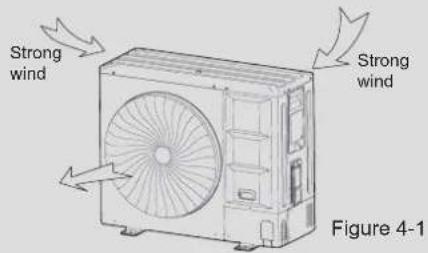
Supposing the wind direction during the operation season of the discharge port is set at a right angle to the wind direction.
4.1.2 Installation space (Unit: mm)
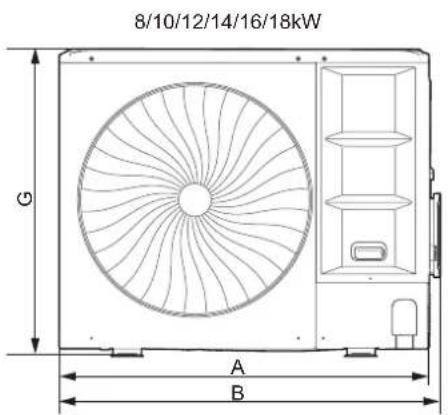
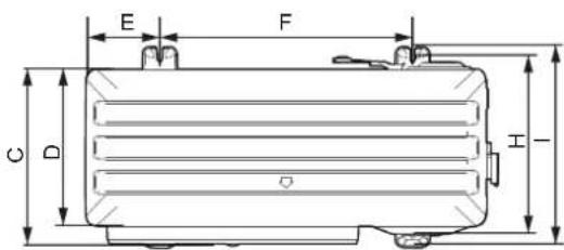
Figure 4-2
Table 4-1(unit:mm)
| Model | 8/10/12/14/16/18kW |
| A | 1038 |
| B | 1073 |
| C | 454 |
| D | 409 |
| E | 191 |
| F | 656 |
| G | 864 |
| H | 463 |
| I | 523 |
| Drawing No. | Figure 4-2 |
■ Single unit installation
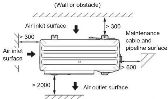
Figure 4-3
■ Parallel connect the two units or above
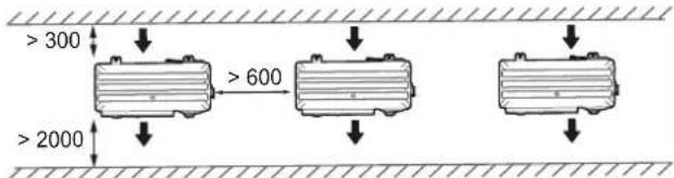
Figure 4-4
■ Parallel connect the front with rear sides
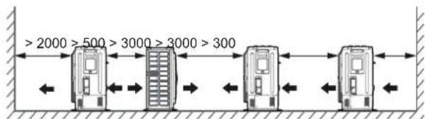
Figure 4-5

CAUTION
- Keep a distance of 2000mm or more between the unit and the wall surface when the discharge port faces to the wall of the building.
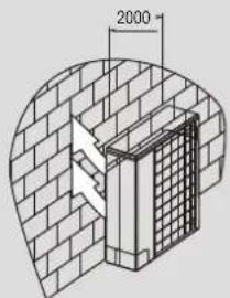
Figure 4-6
4.2 Selecting and Preparing the Refrigerant Piping
4.2.1 Refrigerant piping requirements
NOTE
The R32 refrigerant pipeline system must be kept strictly clean, dry and sealed.
- Cleaning and drying: prevent foreign objects (including mineral oil or water) from mixing into the system.
- Seal: R32 does not contain fluorine, does not destroy the ozone layer, and does not deplete the ozone layer that protects the earth from harmful ultraviolet radiation. But if it is released, R32 can also cause a slight greenhouse effect. Therefore, you must pay special attention when you check the quality of the installation seal.
-
The piping and other pressure vessels must comply with the applicable laws and be suitable for use with the refrigerant. Use only phosphoric acid deoxidized seamless copper for the refrigerant piping.
-
Foreign objects in the pipes (including lubricant used during pipe bending) must be ≤ 30 mg/10 m.
• Calculate all piping lengths and distances.
4.2.2 Design considerations
NOTE
- The amount of brazing required should be kept to a minimum.
- As bends cause pressure loss when transporting refrigerant, the fewer bends in the system, the better it is. Piping length needs to take the equivalent length of bends into account (the equivalent length of each branch joint is 0.5 m).
- On the two inside sides of the first branch joint, the system should, as far as possible, be equal in terms of the number of units, total capacities and total piping lengths.
- The refrigerant shut-off device (RSD) is optional. Please contact the local dealer for purchase. Referigerant shut-off device shall be located outside, installed on the main pipe and close to the first branch joint. For more detailed instructions, please refer to the corresponding installation and operation manual.
4.2.3 Piping and component definition
Table 4-2
| Definition | Pipe connection position | Code |
| Main pipe | The pipe between the outdoor unit and the first branch joint. | L1 |
| Indoor unit main pipe | The pipe between the branch joints. | L2~L5 |
| Indoor unit auxiliary pipe | The pipe between the indoor unit and the nearest branch joint. | a~f |
| Branch joint | The joint connect with the main pipe, the indoor unit main pipe and auxiliary pipe. | A~E |
| Indoor unit | / | N1~N6 |
■ Schematic diagram of the allowable length and height difference for refrigerant piping
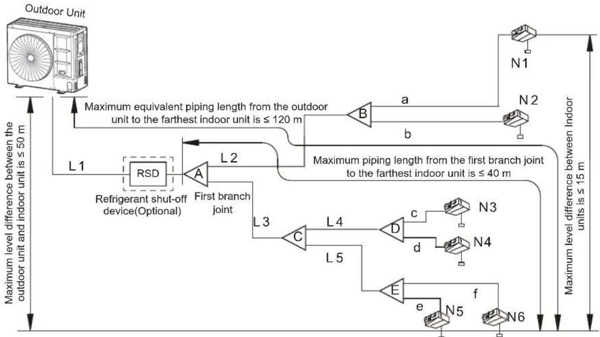
flowchart
graph TD
    A["Outdoor Unit"] -->|Maximum equivalent piping length from the outdoor unit to the farthest indoor unit is ≤ 120 m| B["Refrigerant shut-off device(Optional)"]
    B --> C["L1"]
    C --> D["RSD"]
    D --> E["L2"]
    E --> F["A"]
    F --> G["First branch joint"]
    G --> H["L3"]
    H --> I["C"]
    I --> J["L4"]
    J --> K["D"]
    K --> L["c"]
    L --> M["N3"]
    K --> N["d"]
    N --> O["N4"]
    H --> P["L5"]
    P --> Q["E"]
    Q --> R["f"]
    R --> S["N5"]
    S --> T["N6"]
    T --> U["N1"]
    U --> V["N2"]
    V --> W["a"]
    W --> X["b"]
    X --> Y["Maximum piping length from the first branch joint to the farthest indoor unit is ≤ 40 m"]
    style A fill:#f9f,stroke:#333
    style V fill:#f9f,stroke:#333
Figure 4-7
4.2.4 Allowable length and height difference for refrigerant piping
Table 4-3
| Permitted value Piping | |||||
| Piping Length | Total piping length (Actual) | ≤ 150 m (8/10 kW)≤ 300 m (12/14/16/18 kW) | L1+L2+L3+L4+L5+a+b+c+d+e+f | ||
| Piping length between the outdoor unit and the farthest indoor unit | Actual | ≤ 50 m (8/10 kW)≤ 100 m (12/14/16/18 kW) | L1+L2+ max(a,b) or L1+L3+L4+max(c,d) or L1+L3+L5+max(e,f) | ||
| Equivalent | ≤ 60 m (8/10 kW)≤ 120 m (12/14/16/18 kW) | ||||
| Piping length between the first branch and the furthest indoor unit | ≤ 30 m (8/10 kW)≤ 40 m (12/14/16/18 kW) | L2+max(a,b,c,d) or L3+max(e,f,g,h,i) | |||
| Level difference | Outdoor unit to indoor unit | Outdoor unit is above | ≤ 30 m (8/10 kW)≤ 50 m (12/14/16/18 kW) | — | |
| Outdoor unit is below | ≤ 20 m (8/10 kW)≤ 40 m (12/14/16/18 kW) | — | |||
| Indoor unit to indoor unit | ≤ 15 m | — | |||
NOTE
It is recommended that an oil return bend with dimensions as specified in Figure 4-8 is set every 10 m in the gas pipe of the main pipe.
Oil return bend (unit: mm)
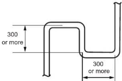
Figure 4-8
4.2.5 Refrigerant pipe selection
Select refrigerant pipe and branch joint according to Table 4-4 to 4-7.
NOTE
- Branch header can also be selected to connect pipes and indoor units. Meanwhile, the relevant requirements in the Owner's Manual and Installation manual must be followed
- The selection of branch header depends on the quantity of branches it connects to.
- Branches and other branch heads cannot be installed downstream of the initial head branch.
Main pipes (L1) and first branch joint kit (A) according to the outdoor unit
Table 4-4
| Outdoor unit capacity (kW) | The equivalent piping length from outdoor units to the farthest indoor unit is < 90 m (mm OD) | Branch joint kit | |
| Gas pipe (Φ) | Liquid pipe (Φ) | ||
| 8~10 | Φ15.9 | Φ9.52 | FQZHN-01D |
| 12~18 | Φ15.9 | Φ9.52 | FQZHN-01D |
Table 4-5
| Outdoor unit capacity (kW) | The equivalent piping length from outdoor units to the farthest indoor unit is ≥ 90 m (mm OD) | Branch joint kit | |
| gas pipe (Φ) liquid pipe (Φ) | |||
| 8~10 | Φ15.9 | Φ9.52 | FQZHN-01D |
| 12~18 | Φ19.1 | Φ9.52 | FQZHN-01D |
NOTE
When the equivalent piping length from outdoor unit to the farthest indoor unit is ≥90 m, it must increase the size of main gas pipe as shown in Table 4-5.
Pipe diameter and branch joint kits between the outdoor unit and indoor units according to downstream indoor unit
Table 4-6
| Total capacity of the downstream indoor units (×100 W) | Indoor unit main pipe size (mm OD) | Branch joint kit | |
| Gas pipe (Φ) | Liquid pipe (Φ) | ||
| A<63 | Φ12.7 | Φ6.35 | FQZHN-01D |
| 63≤A<160 | Φ15.9 | Φ9.52 | FQZHN-01D |
| 160≤A≤280 | Φ19.1 | Φ9.52 | FQZHN-01D |
NOTE
- The corresponding maximum values listed in Table 4-4, Table 4-5 and Table 4-6 should be used as the main pipe (L1) size and the first branch joint (A) size.
- Choose indoor unit main pipes and branch joints between the first branch joint and indoor units from the above table in accordance with the total capacity of all the indoor units connected downstream.
Indoor unit auxiliary pipe (a\~f)
Table 4-7
| Indoor unit capacity (×100 W) | Indoor unit pipe size (mm OD) | |
| Gas pipe (Φ) Liquid pipe (Φ) | ||
| A<63 | Φ12.7 | Φ6.35 |
| 63≤A<160 | Φ15.9 | Φ9.52 |
The pipe thickness of the refrigerant piping shall comply with the applicable legislation.
The minimal pipe thickness for R32 piping must be in accordance with the table below.
Table 4-8
| Piping outer diameter (mm) | Minimum thickness (mm) | Temper grade |
| ø6.35 | 0.80 | M-type |
| ø9.52 | 0.80 | M-type |
| ø12.7 | 1.00 | M-type |
| ø15.9 | 1.00 | M-type |
| ø19.1 | 1.00 | M-type |
| ø22.2 | 1.00 | Y2-type |
NOTE
- Material: Only seamless phosphorus -deoxidized copper piping that complies with all applicable legislation should be used.
- Thicknesses: Temper grades and minimum thicknesses for different diameters of piping should comply with local regulations.
- Design pressure of R32 refrigerant is 4.3 MPa (43 bar).
An example of refrigerant piping selection
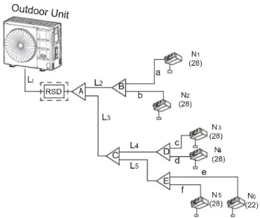
flowchart
graph TD
    A["Fan"] -->|L1| B["RSD"]
    B --> C["A"]
    C --> D["L2"]
    D --> E["B"]
    E --> F["a"]
    E --> G["b"]
    G --> H["N1 (28)"]
    E --> I["N2 (28)"]
    C --> J["L3"]
    J --> K["C"]
    K --> L["L4"]
    L --> M["D"]
    M --> N["c"]
    N --> O["N3 (28)"]
    L --> P["L5"]
    P --> Q["d"]
    Q --> R["N4 (28)"]
    M --> S["e"]
    S --> T["N5 (28)"]
    M --> U["f"]
    U --> V["N6 (22)"]
Figure 4-9
The example below illustrates the piping selection procedure for a system consisting of an outdoor unit (16kW) and 6 indoor units (2.2 kW×1+2.8 kW×5), as shown in Figure 4-9. The equivalent piping length from the outdoor units to the farthest indoor unit is not more than 90 m.
- Select main pipe (L1) and first branch joint (A)
The outdoor unit capacity is 16kW , and the equivalent piping length from the outdoor units to the farthest indoor unit is not more than 90m . So refer to Table 4-4, the main gas liquid pipe size is 15.9 and 9.52 respectively.
The downstream indoor unit capacity is 16.2 kW. Then check Figure 4-6 to get the main gas/liquid pipe size of 19.1/ 9.52. According to the maximum value principle, it should apply the 19.1/ 9.52, and the first branch joint A is FQZHN-01D.
- Select indoor main pipe (L2\~L5) and branch joint (B\~E)
The downstream indoor units of L2 are N1 to N2, with the capacity of 5.6 kW. Referring to Table 4-6, the gas and liquid pipe size of L2 are 12.7 and 6.35 respectively, and the branch joint B is FQZHN-01D.
Similarly, the pipe size of L3 is 15.9 and 9.52 , the pipe size of L3 and L4 is 15.9 and 9.52 , and the branch joint B\~E are all FQZHN-01D.
- Select the indoor unit auxiliary pipe (a to i)
The capacity of indoor unit N1 to N6 is all less than 6.3 kW. According to Table 4-7, the pipe size from a to f is respectively 12.7 and 6.35 .
5 OUTDOOR UNIT INSTALLATION
5.1 Preparing the Structure for Installation
- Make concrete foundation according to the specifications of the outdoor units (refer to Figure 5-1).
- Fasten the feet of this unit with bolts firmly to prevent it from collapsing in the event of an earthquake or strong winds (refer to Figure 5-1).
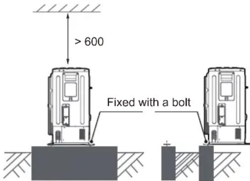
Figure 5-1
5.2 Things to Note When Connecting the Refrigerant Piping
CAUTION
• Take appropriate precautions to prevent refrigerant leakage and ventilate the area immediately if the refrigerant leaks, as high concentration of R32 refrigerant in an enclosed area can cause poisoning or fire.
- Refrigerant must be recovered. Do not release it into the environment. Use professional fluorine extraction equipment to extract the refrigerant from the unit.
NOTE
- Make sure the refrigerant piping is installed in accordance with applicable laws.
- Make sure the piping and connections are not placed under pressure.
- Before brazing, the refrigerant piping should be flushed with oxygen free nitrogen (OFN) to remove dust, moisture and other particles. Never use outdoor unit refrigerant.
- Do not open the stop valves until confirming that all the piping connections have been completed and there are no gas leaks in the system.
5.3 Refrigerant Piping Connection
CAUTION
- Please be careful to avoid the components while connecting to the connecting pipes.
- Low temperature solder alloys, such as lead/tin alloys, are not acceptable for pipe connections or any other refrigerant pressure containing purposes.
• Vacuum before welding, if necessary, to ensure that there is no R32 residue in the piping. - Oxygen free nitrogen (OFN) shall be purged through the system both before and during the brazing process.
The indoor and outdoor connecting pipe interface and power line outlet.
Various piping and wiring patterns can be selected, such as exiting from the front, the back, the side, and undersurface, etc.
(The following displays the locations of several piping and wiring knock-off interfaces)
The connection method of flaring(8/10/12/14/16/18kW)
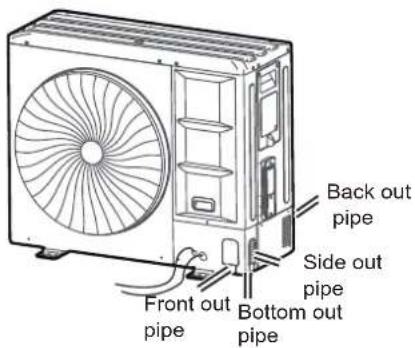
Figure 5-2
Forward piping connection mode (8/10/12/14/16/18kW)
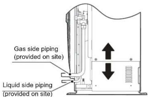
Figure 5-3
Side outlet connection mode
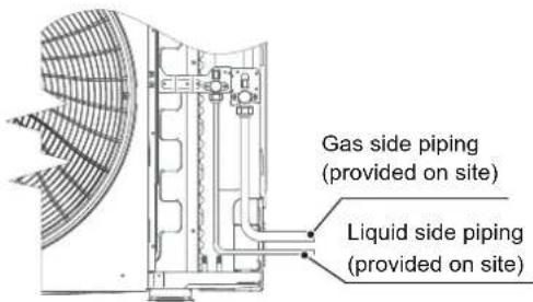
Figure 5-4
Outlet piping connection mode
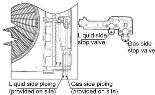
Figure 5-5
Back outlet piping connection mode
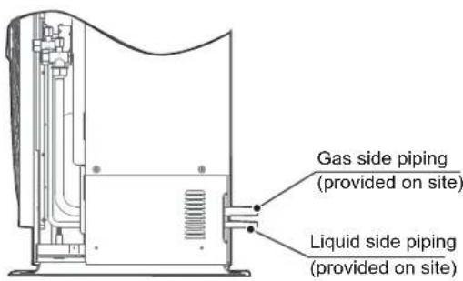
Figure 5-6
CAUTION
- Side out pipe: please remove the L-shape metal plate, otherwise wiring cannot be completed.
- Back outlet pipe: please wipe off the piping support rubber blanket beside the inner outlet pipe cover of the machine while the pipe exits from the back.
- Front outlet pipe: cut the frontal hole of the pipe-outlet plate. The method for the outlet pipe is the same as the back outlet pipe.
- Undersurface outlet pipe: the knock out should from inside to outside, and then piping and wiring should be fed through this. Make sure that the fat connecting pipe exits through the largest hole, otherwise the pipes will rub together. Please do the moth proofing for the created hole, to avoid pests from entering into and destroying the components.
5.4 Leak Detection
Electronic leak detectors shall be used to check whether air leaks at each joint.
• A and B indicate check valves of ODU.
• C and D indicate IDU connecting pipe ports.
- All of the connection ports between the branch header and refrigerant pipe.
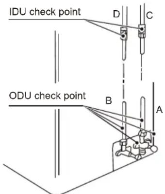
Figure 5-7
WARNING
- Under no circumstances shall potential sources of ignition be used to search for or detect refrigerant leaks. A halide torch (or any other detector using a naked flame) shall not be used.
5.5 Heat Insulation
Carry out heat insulation treatment for the pipes at the gas and liquid sides respectively. Pipes on the liquid and gas sides have a low temperature during cooling. Take sufficient insulation measures to prevent condensation (see Figure 5-8).
The gas pipe must be treated with the closed-cell foam insulation material, which is rated at a non-flammable level of B1 and heat resistance of over 120^ C.
When the outer diameter of the copper pipe is not greater than 12.7 mm, the thickness of insulation layer should be greater than 15mm.
When the outer diameter of the copper pipe is equal to or greater than 15.9 mm, the thickness of the insulation layer should be greater than 20 mm.
The attached insulation material for the part of the IDU where the pipe connects must undergo heat insulation treatment without gaps.
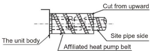
Figure 5-8
5.6 Airtight Test
Air tightness test – OFN must be used.
Increase the pressure from the liquid pipe and gas pipe to 4.0 MPa at the same time (not exceeding 4.0 MPa). If the pressure does not drop in 24 hours, the test is passed.
When the pressure drops, check the leakage position.
After you make sure that there is no leakage, discharge the nitrogen.
CAUTION
- Never use oxygen, combustible gas, or poisonous gas in the air tightness test.
- To prevent damage to the equipment, the pressure must not be held for too long.
5.7 Air Purge with Vacuum Pump
- Use a vacuum pump that can evacuate the pipe to a pressure of less than -100.7 kPa (5 Torr, -755 mmHg). When the pump is stopped, do not let the pump oil flow back into the refrigerant pipe.
- The liquid and gas pipes should be evacuated with a vacuum pump for more than two hours to a pressure of less than -100.7kPa.
- Then, place the pipes at pressure of less than -100.7 kPa for more than one hour, and check whether the reading of the vacuum gauge rises.
(If the reading rises, there is residual water or gas leakage in the system. The leakage must be checked and solved and the test should be performed again.)
- Water may enter into pipes under the following circumstances: the installation is carried out in a rainy season and the installation period is long; the pipes are condensed inside; rainwater enters the pipes.
- After the above vacuum drying of two hours, use nitrogen to increase the pressure to 0.05 MPa (vacuum breaking), and use a vacuum pump to decrease the pressure to lower than -100.7kPa or below and hold the pressure for one hour (vacuum drying).
- If the pressure cannot be decreased to lower than -100.7 kPa after two-hour vacuumizing, repeat the vacuum breaking and vacuum process. After that, place the vacuum pipes for one hour, and then check whether the reading of the vacuum gauge rises.
WARNING
- During the maintenance process, it is necessary to enter the vacuum mode when vacuumizing.
- If the system is configured with a refrigerant shut-off device, vacuuming needs to be done from the maintenance needle valves of the ODU check valves and the refrigerant shut-off device separately. In additional, only vacuuming from the ODU is also allowed when the system is powered on and the ODU is without any error code of Ad1, C21, C26, C28, C2A and EC1.

CAUTION
- Use a vacuum pump to perform the vacuumizing process. Do not use refrigerant gas to discharge air.
- Use a vacuum pump that can vacuumize the pipe to a pressure of less than -100.7 kPa (5 Torr, -755 mmHg). When the pump is stopped, do not let the pump oil flow back into the refrigerant pipe.
- In order to prevent the entry of impurities, the R32 special tool must be used to ensure the compression strength. Use a filling hose with a top rod to connect to the maintenance access of the check valve or the refrigerant filling port.
5.8 Refrigerant Amount to be Added

WARNING
- Use only R32 as the refrigerant. Other substances may cause explosions and accidents.
- R32 contains fluorinated greenhouse gases, and the GWP value is 675. Do not discharge the gas into the surroundings.
- When charging the refrigerant, make sure you wear protective gloves and safety glasses. Be careful when you open the refrigerant piping.
- Charge the refrigerant only after the system has not failed the gas tightness tests and vacuum drying.
- Ensure that the refrigeration system is earthed prior to charging the system with refrigerant.
- Add the refrigerant amount according to the calculation results. Extreme care shall be taken not to overfill the refrigeration system.
- The system shall be leak tested on completion of charging but prior to commissioning. A follow up leak test shall be carried out prior to leaving the site.
- If the system is configured with a refrigerant shut-off device, charging may need to be done separately from the maintenance needle valves of the ODU check valves and the refrigerant shut-off device. In addition, only charging from the ODU is also allowed when the system is powered on and the ODU is without any error code of Ad1, C21, C26, C28, C2A and EC1.

NOTE
- Make sure all connected indoor units have been identified.
- Hoses or lines shall be as short as possible to minimize the amount of refrigerant contained in them.
• Cylinders shall be kept upright. - Label the system when charging is complete (if it is not already labeled).
5.8.1 Calculating additional refrigerant charge
The additional refrigerant charge required depends on the lengths and diameters of the outdoor and indoor liquid pipes and the indoor unit capacity of the connection. Table 5-1 and Table 5-2 show the additional refrigerant charge required under different conditions.
Additional refrigerant charge amount R1 (according to liquid pipe lengths and diameters)
Table 5-1
| Liquid piping diameter (mm OD) | Additional refrigerant charge per meter of equivalent length of liquid piping (kg) |
| Φ6.35 | 0.019 |
| Φ9.52 | 0.049 |
| Φ12.7 | 0.096 |
| Φ15.9 | 0.153 |
The additional refrigerant charge amount (R1) is obtained by adding the additional charge requirements for each of the outdoor and indoor liquid pipes, as in the following formula, where L1 to L4 represent the equivalent lengths of the pipes of different diameters.
Additional refrigerant charge amount R1 (kg) = L1 (Φ6.35) × 0.019 + L2 (Φ9.52) × 0.049 + L3 (Φ12.7) × 0.096 + L4 (Φ15.9) × 0.153
Additional refrigerant charge amount R2 (according to connected indoor unit capacity)
Table 5-2
| Connected indoor unit capacity (× 1000W) | Additional refrigerant charge per 1000W capacity (kg) |
| A 0.0238 |
Additional refrigerant charge amount R2 = A × 0.0238
Table 5-3
Total additional refrigerant charge amount (R) is equal to the sum of R1 and R2. Calculate the amount of refrigerant to be charged according to the formula below:
$$ R = R 1 + R 2. $$

WARNING
- The total refrigerant charge of the system, including factory charge and additional charge, must not exceed the maximum design refrigerant charge of 12 kg.
Determine the total refrigerant charge amount of the system:
Total charge (Mc) = factory charge + additional charge = R0 + R.
The factory charge (R0) can be obtained from Table 9-1.
6. ELECTRICAL WIRING
6.1 Safety Device Requirements
- Select the wire diameters (minimum value) individually for each unit based on the rated current, as shown in Table 6-1 and Table 6-2.
- For thee-phase units, the maximum allowable voltage range variation between phases is 2%.
- Select a circuit breaker that has a contact separation in all poles not less than 3 mm providing full disconnection, where MFA is used to select the current circuit breakers and residual current operation breakers.
- The current carrying capacity of the conductor wire is only for users' reference. The actual current carrying capacity has different correction coefficients depending on the cable type and length, the pipe penetration method, and the actual laying environment. Users are recommended to make corrections according to local regulations and specific installation circumstances.
Table 6-1
| Rated current of appliance (A) | Nominal cross-sectional area ( mm^2 ) | |
| Flexible cords | Cable for fixed wiring | |
| ≤ 3 | 0.5 and 0.75 | 1 to 2.5 |
| >3 and ≤ 6 | 0.75 and 1 | 1 to 2.5 |
| >6 and ≤ 10 | 1 and 1.5 | 1 to 2.5 |
| >10 and ≤ 16 | 1.5 and 2.5 | 1.5 to 4 |
| >16 and ≤ 25 | 2.5 and 4 | 2.5 to 6 |
| >25 and ≤ 32 | 4 and 6 | 4 to 10 |
| >32 and ≤ 50 | 6 and 10 | 6 to 16 |
| >50 and ≤ 63 | 10 and 16 | 10 to 25 |
Table 6-2
| Power Supply | Outdoor UnitModel | Power Current | Compressor F | Fan Motor | ||||||||
| Capacity (kW) | Voltage (V) | Frequency (Hz) | Min. (V) | Max. (V) | MCA (Rated current) (A) | TOCA (A) | MFA (A) | MSC (A) | RLA (A) | Power (kW) | FLA (A) | |
| 220-240V~50Hz | 8 | 220-240 | 50 | 198 | 264 | 21.3 | 18 | 25 | - | 15.9 | 0.2 | 1.0 |
| 10 | 220-240 | 50 | 198 | 264 | 24 | 20 | 25 | - | 17.9 | 0.2 | 1.0 | |
| 12 | 220-240 | 50 | 198 | 264 | 32 | 27 | 32 | - | 24.8 | 0.2 | 1.2 | |
| 14 | 220-240 | 50 | 198 | 264 | 35 | 29 | 40 | - | 26.8 | 0.2 | 1.2 | |
| 16 | 220-240 | 50 | 198 | 264 | 40 | 33 | 40 | - | 30.3 | 0.2 | 1.2 | |
| 18 | 220-240 | 50 | 198 | 264 | 40 | 33 | 40 | - | 30 | 0.2 | 1.5 | |
| 380-415V 3N~50Hz | 12 | 380-415 | 50 | 342 | 440 | 14 | 13 | 20 | - | 10.4 | 0.2 | 0.6 |
| 14 | 380-415 | 50 | 342 | 440 | 15 | 14 | 20 | - | 11.4 | 0.2 | 0.6 | |
| 16 | 380-415 | 50 | 342 | 440 | 17 | 15 | 20 | - | 12.9 | 0.2 | 0.6 | |
| 18 | 380-415 | 50 | 342 | 440 | 17 | 15 | 20 | - | 12.9 | 0.2 | 0.7 | |
i INFORMATION
Phase and frequency of power supply system: 1N\~50Hz, Voltage: 220-240V; 3N\~50Hz, Voltage: 380-415V
Abbreviations:
MCA: Minimum Circuit Amps; TOCA: Total Over-current Amps; MFA: Maximum Fuse Amps; MSC: Maximum Starting Current (A); RLA: Rated Load Amps; FLA: Fan Load Amps.
- For three-phase units, units are suitable for use in electrical systems where voltage supplied to unit terminals is not below or above listed range limits. The maximum allowable voltage variation between phases is 2%.
- Select wire size based on the value of MCA, which means the rated current in Table 6-1.
• TOCA indicates the total overcurrent amps value of each OC set. - MFA is used to select overcurrent circuit breakers and residual-current circuit breakers.
- MSC indicates the maximum current on compressor start-up in amps.
- RLA is based on the following conditions: indoor temperature 27°C DB, 19°C WB; outdoor temperature 35°C DB.

NOTE
- If the power supply lacks N phase or there is an error in the N phase, the device will malfunction.
- Some power equipment may have an inverted phase or intermittent phase (such as a generator). For this type of power source, a reverse-phase protection circuit should be installed locally in the unit. as Operating in the inverted phase may damage the unit.
- Do not share the same power supply line with other devices.
- The power cord may produce electromagnetic interference so you should maintain a certain distance from equipment that may be susceptible to such interference.
- Separate power supply for the indoor and outdoor units.

WARNING
• Take note of the risk of electric shocks during installation.
- All the electric wires and components must be installed by a certified electrician, and the installation process must comply with applicable regulations.
- Use only wires with copper cores for the connections.
- A main breaker or safety device that can disconnect all polarities must be installed, and the breaker device can be completely disconnected in situations where there is excessive voltage
- Wiring must be carried out in strict accordance with what is stated on the product nameplate.
- Do not squeeze or pull the unit connection, and make sure the wiring is not in contact with the sharp edges of the sheet metal.
- Make sure the grounding connection is safe and reliable. Do not connect the earth wire to public pipes, telephone earth wires, surge absorbers and other places that are not designed for grounding. Improper grounding may cause electric shock.
- Make sure the fuses and circuit breakers installed meet the corresponding specifications.
- Make sure an electric leakage protection device is installed to prevent electric shocks or fires.
- The model specifications and characteristics (anti high-frequency noise characteristics) of the electric leakage protection device should be compatible with the unit to prevent frequent tripping.
- Before powering the unit on, make sure the connections between the power cord and terminals of the components are secure, and the metallic cover of the electric control box is closed tightly.
6.2 Connecting the Power Cord

NOTE
- Do not connect the power supply to the communication terminal block. Otherwise, the whole system may fail.
- You must first connect the earth line (note that you should use only the yellow-green wire to connect to the earth, and you must turn off the power supply when you are connecting the earth line) before you connect the power cord. Before you install the screws, you must first comb through the path along the wiring to prevent any part of the wiring from becoming exceptionally loose or tight because of inconsistencies in the lengths of the power cord and earth line.
- The wire diameter must comply with the specifications, and the terminal should be screwed tightly. Do not subject the terminal to any external force.
- Seal the wiring connection with insulation material, or condensation may occur.
■ Use round-type terminals of the correct specifications to connect the power cable
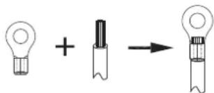
Fig. 6-1

WARNING
- When inserting the strong-current cables and communication lines into the wiring holes, they must be equipped with wiring across rings to avoid being worn.
■ Wiring Terminal Description
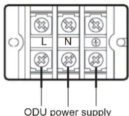
220-240V\~50Hz
Fig. 6-2
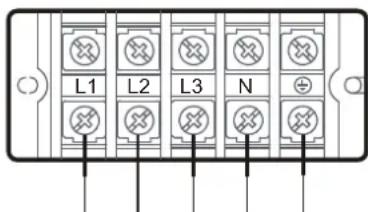
ODU power supply
380-415V 3N\~50Hz
Fig. 6-3
6.3 Connecting the Communication Wiring
NOTE
- For a single-phase system, the EMI effect of the communication line M1M2 (or PQE) can be improved by adding a magnetic ring. The installation is shown in the figure below. The magnetic ring needs to be fixed with the communication line (it can be wound for one or more turns), and placed in the machine to prevent it from falling off.
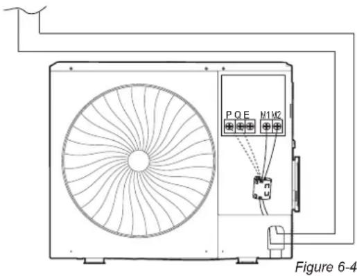
- Wiring layout is comprised of the communication wiring between the indoor and outdoor units. These include the earth lines, and the shielded layer of the earth lines of the indoor units in the communication line. See below the wiring layout of outdoor unit.
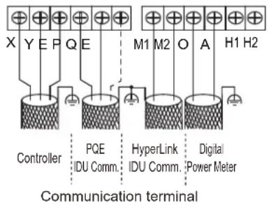
Figure 6-5
WARNING
- Do not connect the communication line when the power is on.
- Connect the shielding nets at both ends of the shielded wire to the sheet metal “ 盆 ” of the electronic control box.
- Do not connect the power cable to the terminal of communication line, otherwise, the motherboard will be damaged.
- Do not connect a system with both HyperLink (M1 M2) communication lines and PQ communication lines.
CAUTION
- On-site wiring must comply with the relevant regulations of the local country/region and must be completed by professionals.
- The communication lines of the IDUs and ODU can only be led out and connected from the ODU.
- When a single communication line is not long enough, the joint must be crimped or soldered, and the copper wire at the joint shall not be exposed.
• Applicable standards: EN 55014-1 and EN 55014-2. The communication line must be shielded wire.
Before connecting the communication wiring, please select the appropriate connection method. Refer to the following table:
Table 6-3 communication mode
| Optional communication mode of IDU and ODU |
| HyperLink (M1 M2) communication |
| RS-485 (P Q) communication |
Table 6-4 Communication wiring material
| Communication mode Type of wire | Number of cores and wire diameter (mm2) | Total length of communication line (m) | |
| RS-485 (P Q) communication | PVC-sheathed copper-core flexible shielded twisted pair | 2x0.75 L≤1200 | |
| HyperLink (M1 M2) communication | PVC-sheathed copper-core flexible shielded twisted pair | 2x0.75 | L≤2000 |
• HyperLink (M1 M2) communication
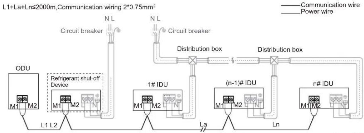
flowchart
graph TD
    A["ODU"] --> B["L1 L2"]
    B --> C["Refrigerant shut-off Device"]
    C --> D["N L"]
    D --> E["Circuit breaker"]
    E --> F["Distribution box"]
    F --> G["n# IDU"]
    G --> H["Distribution box"]
    H --> I["(n-1)# IDU"]
    I --> J["Ln"]
    J --> K["n# IDU"]
    style A fill:#f9f,stroke:#333
    style F fill:#ccf,stroke:#333
    style H fill:#cfc,stroke:#333
Figure 6-6
CAUTION
- Keep the power on/off for all IDUs.
- Do not connect the HyperLink (M1 M2) communication line to the PQ or D1D2 communication line.
• Arbitrary topology wiring. - Separate power supply for the indoor units and refrigerant shut-off device.
• Applicable standards: EN 55014-1 and EN 55014-2. The communication line must be shielded wire.
• RS-485(P Q) communication
L1+La+Ln≤1200m, Communication wiring 2*0.75mm²
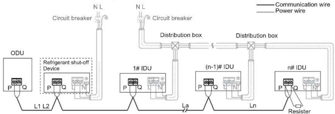
flowchart
graph TD
    A["ODU"] --> B["L1 L2"]
    B --> C["Refrigerant shut-off Device"]
    C --> D["N L"]
    D --> E["Circuit breaker"]
    E --> F["Distribution box"]
    F --> G["1# IDU"]
    G --> H["La"]
    H --> I["(n-1)# IDU"]
    I --> J["Ln"]
    J --> K["n# IDU"]
    K --> L["Resister"]
    style A fill:#f9f,stroke:#333
    style F fill:#ccf,stroke:#333
    style G fill:#cfc,stroke:#333
    style I fill:#fcc,stroke:#333
    style K fill:#cff,stroke:#333
Figure 6-7
CAUTION
- After the last indoor unit, the communication wiring should not route back to the outdoor unit as this will form a closed loop.
• In the last indoor unit, connect a resistor of 120 ohms between the P and Q terminals. - Do not bind the communication line, refrigerant piping and power cable together.
- When the power cable and communication line are laid in parallel, the distance between the two lines must be 5cm or more to prevent signal source interference.
- All IDUs in a system must be powered through a power supply so that they can be powered on or off at the same time.
- All communication lines of the IDUs and ODU must be connected in a series, use the shielded wire, and the shield layer must be grounded.
-
Separate power supply for the indoor units and refrigerant shut-off device.
• Applicable standards: EN 55014-1 and EN 55014-2. The communication line must be shielded wire. -
XYE, OA communication wiring
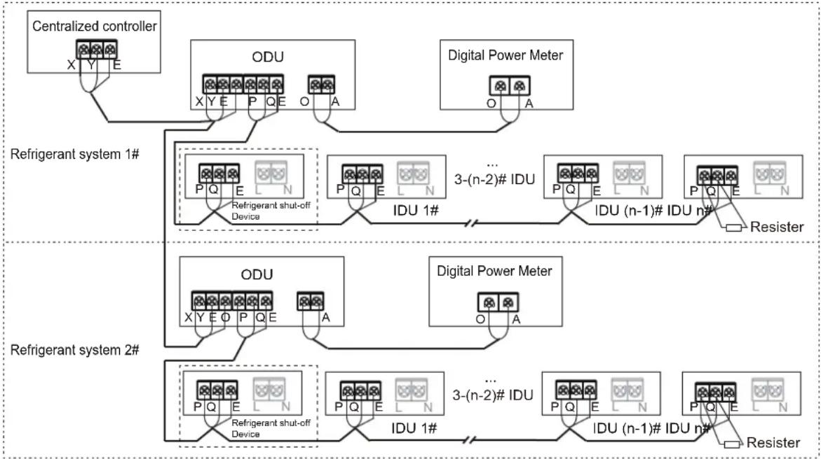
flowchart
graph TD
    A["Centralized controller"] --> B["ODU"]
    B --> C["Digital Power Meter"]
    C --> D["Refrigerant system 1#"]
    D --> E["Refrigerant shut-off Device"]
    E --> F["3-(n-2)# IDU"]
    F --> G["IDU (n-1)# IDU n#"]
    G --> H["Resister"]
    I["Refrigerant system 2#"] --> J["ODU"]
    J --> K["Digital Power Meter"]
    K --> L["Refrigerant shut-off Device"]
    L --> M["3-(n-2)# IDU"]
    M --> N["IDU (n-1)# IDU n#"]
    N --> O["Resister"]
Figure 6-8
CAUTION
- The cross-sectional area of each core of the communication wiring is not less than 0.75 mm^2 , and the length must not exceed 1200 m .
- Connect the shielding nets at both ends of the shielded wire to the sheet metal “ A ” of the electronic control box.
- The centralized controller and digital electric meter are optional accessories. Please contact the local dealer for purchase if needed.
- Applicable standards: EN 55014-1 and EN 55014-2. The communication line must be shielded wire.
7 CONFIGURATION
7.1 Overview
This chapter describes how the system configuration can be implemented once the installation is complete, and other relevant information.
It contains the following information:
- Implement field settings
• Energy-saving and optimized operation
• Using the Leak Check function

INFORMATION
Installation personnel should read this chapter.
7.2 Digital Display and Button Settings
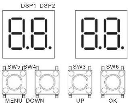
Fig 7-1
7.2.1 Digital display output
Table 7-1
| Outdoor unit state | Parameters displayed on DSP1 | Parameters displayed on DSP2 |
| Standby Unit's address | The number of indoor units in communication with the outdoor unit | |
| Normal operation | --- | Running speed of the compressor in rotations per second |
| Error or protection | Placeholder and error or protection code | |
| In menu mode | Display menu mode code | |
| System check | Display system check code | |
7.2.2 Function of buttons SW3 to SW6
Table 7-2
| Button | Function |
| SW3 (UP) | In menu mode: previous and next buttons for menu modes. |
| SW4 (DOWN) | Not in menu mode: previous and next buttons for system check information. |
| SW5 (MENU) | Enter / exit menu mode. |
| SW6 (OK) | Confirm to enter specified menu mode. |
7.2.3 Menu mode
-
- Press and hold SW5 "MENU" button for 5 seconds to enter menu mode, and the digital display will display "n1".
- Press SW3 / SW4 "UP / DOWN" button to select the first-level menu "n1", "n2", "n3", "n4" or "nb".
- Press SW6 "OK" button to enter the specified first-level menu, for example, enter "n4" mode.
- Press SW3 / SW4 "UP / DOWN" button to select the second-level menu from "n41" to "n47".
- Press SW6 "OK" button to enter the specified second-level menu, for example, enter "n43" mode.
- Press SW3 / SW4 "UP / DOWN" button to select the specified menu mode code.
- Press SW6 "OK" button to enter specified menu mode.

CAUTION
- Operate the switches and push buttons with an insulated stick (such as a closed ball-point pen) to avoid touching live parts.
Menu mode selection flowchart:
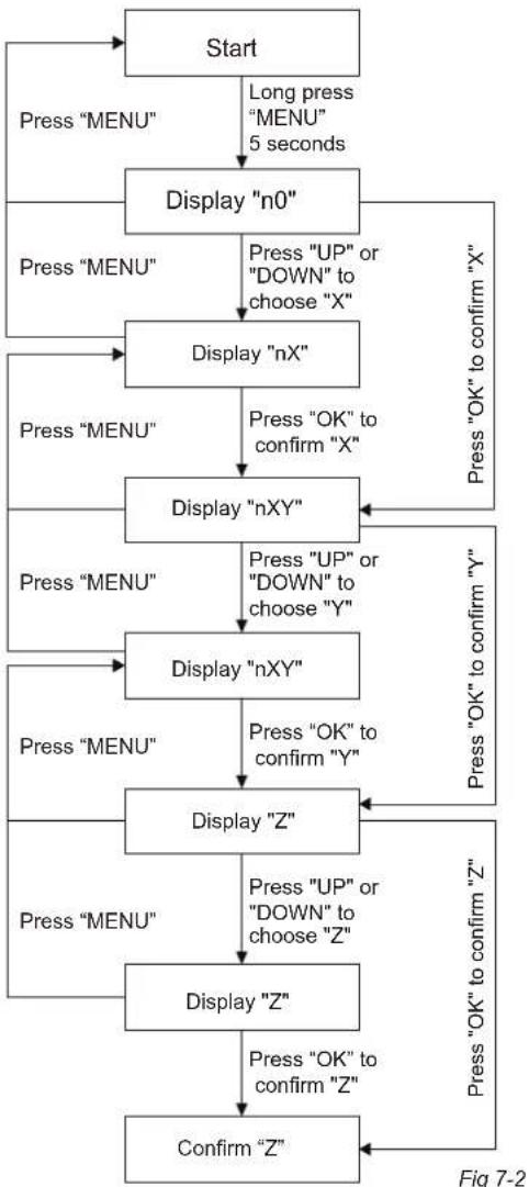
flowchart
graph TD
    A["Start"] --> B["Press "MENU""]
    B --> C["Display "n0""]
    C --> D["Press "MENU""]
    D --> E["Display "nX""]
    E --> F["Press "OK" to confirm "X""]
    F --> G["Display "nXY""]
    G --> H["Press "OK" to confirm "Y""]
    H --> I["Display "Z""]
    I --> J["Press "OK" to confirm "Z""]
    J --> K["Confirm "Z""]
    K --> L["Press "OK" to confirm "Z""]
    L --> M["Display "Z""]
    M --> N["Press "UP" or "DOWN" to choose "Z""]
    N --> O["Press "OK" to confirm "Z""]
    O --> P["Display "Z""]
    P --> Q["Press "OK" to confirm "Z""]
    Q --> R["Display "nXY""]
    R --> S["Press "UP" or "DOWN" to choose "Y""]
    S --> T["Display "nX""]
    T --> U["Press "OK" to confirm "X""]
    U --> V["Display "n0""]
    V --> W["Press "UP" or "DOWN" to choose "X""]
    W --> X["Display "nX""]
    X --> Y["Press "OK" to confirm "X""]
    Y --> Z["Display "nXY""]
    Z --> AA["Press "OK" to confirm "Y""]
    AA --> AB["Display "Z""]
    AB --> AC["Press "OK" to confirm "Z""]
    AC --> AD["Confirm "Z""]
Table 7-3
| First-level menu | Second-level menu | Specified menu mode | Description | Default |
| n0 | 0 | 0 | History error | - |
| 1 | Cleaning history error | |||
| 1 | 0 | Query Indoor unit's address | ||
| 2 | 1 | Driver's version(compressor and fan displayed in turn) | ||
| 3 | - | SN code | ||
| n1 | 1 | 0 | Cooling Test | - |
| 1 | Heating Test | |||
| 2 | Test running | |||
| 2 | 0 | Refrigerant recovery to outdoor unit | ||
| 1 | Refrigerant recovery to indoor unit | |||
| 2 | Balance system refrigerant | |||
| 5 | - | Vacuum mode | ||
| 6 | - | Set VIP indoor unit address | ||
| n2 | 0 | 0 | Automatic priority mode | √ |
| 1 | Cooling priority mode | - | ||
| 2 | VIP indoor unit + voting priority mode | |||
| 3 | In response to heating mode only | |||
| 4 | In response to cooling mode only | |||
| 5 | Heating priority mode | |||
| 6 | Change over | |||
| 7 | Voting priority mode | |||
| 8 | First on priority mode | |||
| 9 | Capability requirements priority mode | |||
| 1 | 0 | Non-silent mode | √ | |
| 1 | Silent mode 1 | - | ||
| 2 | Silent mode 2 | |||
| 3 | Silent mode 3 | |||
| 4 | Silent mode 4 | |||
| 5 | Silent mode 5 | |||
| 2 | 0 | 0 Pa static pressure | √ | |
| 1 | 10 Pa static pressure | - | ||
| 2 | 20 Pa static pressure | |||
| 3 | 30 Pa static pressure | |||
| 4 | 35 Pa static pressure | |||
| n2 | 3 | 40 | Power limitation mode, Maximum current =MCA * setting value | - |
| 41 | ||||
| 42 | ||||
| ~ | ||||
| 98 | ||||
| 99 | ||||
| 100 | √ | |||
| 4 | 0 | Meta function unavailable | - | |
| 1 | Meta function available | √ | ||
| 5 | 0 | Celsius unit | √ | |
| 1 | Fahrenheit unit | - | ||
| 8 | 0 | Dry contact closing effective | √ | |
| 1 | Dry contact opening effective | - | ||
| n3 | 2 | 0 | 0m level difference between indoor unit and outdoor unit | √ |
| 1 | 20m level difference between indoor unit and outdoor unit | - | ||
| 2 | 40m level difference between indoor unit and outdoor unit | |||
| 3 | 50m level difference between indoor unit and outdoor unit | |||
| 4 | 0 | Normal | √ | |
| 1 | High sensible heat mode | - | ||
| 2 | Low temperature mode | |||
| n4 | 1 | - | Network address | 0 |
| 2 | - | Number of indoor units | 1 | |
| 4 | 0 | Auto addressing | √ | |
| 1 | Clear address | - | ||
| 5 | 0 | RS-485 (P Q) communication | √ | |
| 2 | HyperLink (M1 M2) communication | - | ||
| n5 | 1 | 0 | Sensors backup running unavailable | - |
| 1 | Sensors backup running available (Manual) | √ | ||
| 2 | Sensors backup running available (Automatic) | - | ||
| 2 | 0 | Backup operation time setting (1 day) | - | |
| 1 | Backup operation time setting (2 days) | |||
| 2 | Backup operation time setting (3 days) | |||
| 3 | Backup operation time setting (4 days) | |||
| 4 | Backup operation time setting (5 days) | |||
| 5 | Backup operation time setting (6 days) | |||
| 6 | Backup operation time setting (7 days) | √ | ||
| n6 | 0 | 0 | Evaporation temperature setting (Ke0=-3) | - |
| 1 | Evaporation temperature setting (Ke0=0) | |||
| 2 | Evaporation temperature setting (Ke0=3) | |||
| 3 | Evaporation temperature setting (Ke0=6) | √ | ||
| 4 | Evaporation temperature setting (Ke0=7) | - | ||
| 5 | Evaporation temperature setting (Ke0=8) | |||
| 6 | Evaporation temperature setting (Ke0=9) | |||
| 7 | Evaporation temperature setting (Ke0=10) | |||
| 8 | Evaporation temperature setting (Ke0=11) | |||
| 2 | 0 | Condensation temperature setting (Kc0=41) | - | |
| 1 | Condensation temperature setting (Kc0=42) | |||
| 2 | Condensation temperature setting (Kc0=43) | |||
| 3 | Condensation temperature setting (Kc0=44) | |||
| 4 | Condensation temperature setting (Kc0=45) | |||
| 5 | Condensation temperature setting (Kc0=46) | |||
| 6 | Condensation temperature setting (Kc0=48) | √ | ||
| 7 | Condensation temperature setting (Kc0=51) | - | ||
| n8 | 7 | 0 | Non-stop compressor defrosting | √ |
| 1 | Stop compressor defrosting | |||
| 9 | 0 | Self-cleaning unavailable | √ | |
| 1 | Self-cleaning available | - | ||
| A | 0 | Refrigerant shut-off device unavailable | √ | |
| 1 | Refrigerant shut-off device available | - | ||
| n9 | 4 | 0 | Force defrosting | - |
| 1 | Force oil return | |||
| 5 | - | Release central controller emergency stop | - | |
| 7 | 0 | Digital electricity meter | √ | |
| 1 | Pulse electricity meter | - | ||
| nc | 0 | 0 | Dry contact 1 function selection (Cooling only) | - |
| 1 | Dry contact 1 function selection (Heating only) | |||
| 2 | Dry contact 1 function selection (Force incapacity requirements) | |||
| 3 | Dry contact 1 function selection (Force stop) | √ | ||
| 1 | 0 | Dry contact 2 function selection (Cooling only) | - | |
| 1 | Dry contact 2 function selection (Heating only) | |||
| 2 | Dry contact 2 function selection (Force incapacity requirements) | |||
| 3 | Dry contact 2 function selection (Force stop) | √ | ||
| 2 | 0 | Dry contact 3 function selection (Operation signal) | - | |
| 1 | Dry contact 3 function selection (Alarm signal) | √ | ||
| 2 | Dry contact 3 function selection (Compressor running signal) | - | ||
| 3 | Dry contact 3 function selection (Defrosting signal) | |||
| 4 | Dry contact 3 function selection (Refrigerant leakage signal) |
7.2.4 UP/DOWN system check button
Before pressing the UP or DOWN button, allow the system to operate steadily for more than an hour. On pressing the UP or DOWN button, the parameters listed in the following table will be displayed in sequence.
Table 7-4
| CONTENTDISP. DESCRIPTION | ||
| -- | "Standby (ODU address+ IDU quantity)/frequency/special status" | |
| 0 | ODU address | 0 |
| 1 | ODU capacity | Unit: HP |
| 2 | Quantity of ODU | 1 |
| 3 | Quantity of IDUs | 1~12 |
| 4 | Reserved | |
| 5 | Target frequency of ODU | Displacement frequency (1) |
| 6 | Reserved | |
| 7 | Actual frequency of compressor | Actual frequency |
| 8 | Reserved | |
| 9 | Operating mode | 0: OFF |
| 2: Cooling | ||
| 3: Heating | ||
| 10 | Fan speed | Unit: RPM |
| 11 | Reserved | |
| 12 | T2 Average | Actual temperature=DISP. Unit: °C |
| 13 | T2B Average | Actual temperature=DISP. Unit: °C |
| 14 | T3 | Actual temperature=DISP. Unit: °C |
| 15 | T4 | Actual temperature=DISP. Unit: °C |
| 16 | T5 | Actual temperature=DISP. Unit: °C |
| 17 | Reserved | |
| 18 | T6B | Actual temperature=DISP. Unit: °C |
| 19 | T7C1 | Actual temperature=DISP. Unit: °C |
| 20 | Reserved | |
| 21 | T71 | Actual temperature=DISP. Unit: °C |
| 22 | Reserved | |
| 23 | T8 | Actual temperature=DISP. Unit: °C |
| 24 | Ntc | Actual temperature=DISP. Unit: °C |
| 25 | Reserved | |
| 26 | TL | Actual temperature=DISP. Unit: °C |
| 27 | Discharge superheat degree | Actual temperature=DISP. Unit: °C |
| 28 | Primary current | Actual current=DISP./10 Unit: A |
| 29 | Inverter compressor current | Actual current=DISP./10 Unit: A |
| 30 | Reserved | |
| 31 | EEVA position | Actual Value=DISP. *24 |
| 32 | Reserved | |
| 33 | EEVC position | Actual Value=DISP. *4 |
| 34 | Reserved | |
| 35 | High pressure of unit | Actual Pressure=DISP. /100 Unit: MPa |
| 36 | Low pressure of unit | Actual Pressure=DISP. /100 Unit: MPa |
| 37 | Quantity of online IDUs | Actual quantity |
| 38 | Quantity of running IDUs | Actual quantity |
| 39 | Heat exchanger status | [0] OFF |
| [1] C1: Condenser | ||
| [2] D1: Reserved | ||
| [3] D2: Reserved | ||
| [4] E1: Evaporator | ||
| [5] F1: Reserved | ||
| [6] F2: Reserved | ||
| 40 | Special mode | [0] Not in special mode |
| [1] Oil return | ||
| [2] Defrost | ||
| [3] Startup | ||
| [4] Stop | ||
| [5] Quick check | ||
| [6] Self cleaning | ||
| 41 | Silent mode setting | 0~5, 5 represents the most silent |
| 42 | Static pressure mode | [0] 0Pa |
| [1] 10Pa | ||
| [2] 20Pa | ||
| [3] 30Pa | ||
| [4] 35Pa | ||
| 43 | TES | Actual temperature=DISP. Unit: °C |
| 44 | TCS | Actual temperature=DISP. Unit: °C |
| 45 | DC Voltage | Actual voltage. Unit: V |
| 46 | AC Voltage | Actual voltage. Unit: V |
| 47 | Quantity of cooling mode IDUs | |
| 48 | Quantity of heating mode IDUs | |
| 49 | Capacity of cooling mode IDUs | |
| 50 | Capacity of heating mode IDUs | |
| 51 | Refrigerant volume | [0]: No result |
| [1]: Critically insufficient | ||
| [2]: Significantly insufficient | ||
| [3]: Normal | ||
| [4]: Slightly excessive | ||
| [5]: Significantly excessive 0~10, | ||
| 52 | Dirty blockage rate | 0~10, 10 represents the worst |
| 53 | Fan error | |
| 54 | Software version | |
| 55 | Last error code | |
| 56 | Reserved | |
| 57 | Reserved | |
| 58 | Reserved |
(1) Need to convert to current compressor output volume. For 8-10kW: compressor output volume is 22, Target frequency = Actual frequency * 22 / 60; for 12-18kW: compressor output volume is 42, Target frequency = Actual frequency * 42 / 60.
8 COMMISSIONING
8.1 Overview
After installation, and once the field settings have been defined, the installation personnel must verify the correctness of the operations. Follow the steps below to perform the test run.
This chapter describes how the test run can be carried out once the installation is complete, and other relevant information.
The test run usually includes the following stages:
- Review the "Checklist Before Test Run".
- Implement the test run.
- If necessary, correct the errors before the test run completes with exceptions.
- Run the system
8.2 Things to Note During the Test Run
WARNING
- During the test run, the outdoor unit operates at the same time with the indoor units connected to it. It is very dangerous to debug the indoor units during the test run.
- Do not insert your fingers, sticks, or other items into the air inlet or outlet. Do not remove the fan mesh cover. When the fan rotation is set at a high speed, it may cause bodily injury.
NOTE
Note that the required input power may be higher when this unit is run for the first time. This phenomenon is due to the compressor which needs to run for 50 hours before it can achieve a stable operating and power consumption state. Make sure the power supply is turned on 12 hours before operations so that the crankcase heater is properly energized. This is also to protect the compressor.
i INFORMATION
The test run can be carried out when the ambient temperature is within the required range as in Figure 8-1.
Avg. indoor ambient
temperature
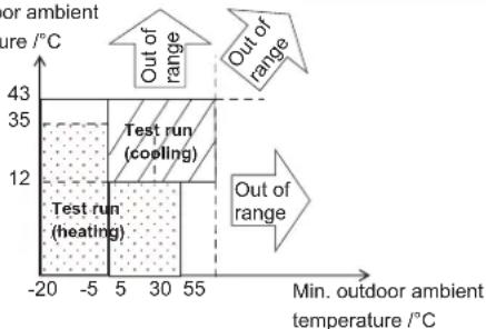
Figure 8-1
During the test run, the outdoor unit and indoor units will start at the same time. Make sure all the preparations for the outdoor unit and indoor units have been completed.
8.3 Checklist Before Test Run
Once this unit is installed, check the following items first. After all the following checks have been completed, you must shut down the unit. This is the only way to start the unit again.
| InstallationCheck if the unit is installed correctly to prevent strange noises and vibrations when the unit starts. | |
| Field wiringBased on the wiring schematic and the relevant regulations, make sure the field wiring is based on the instructions described in section 6.2 and 6.3 on connecting wires. | |
| Earth lineMake sure the earth line is connected correctly, and the grounding terminal is tight. | |
| Insulation test of the main circuitUse the megameter of 500V, apply a voltage of 500V DC between the power terminal and the earth terminal. Check that the insulation resistance is above 2 MΩ. Do not use the megameter on the transmission line. | |
| Fuses, circuit breakers, or protection devicesCheck that the fuses, circuit breakers, or locally installed protection devices comply with the size and type specified in section 6.1 on the requirements for safety devices. Make sure you use fuses and protection devices. | |
| Internal wiringVisually inspect if the connections between the electrical component box and the interior of the unit is loose, or if the electrical components are damaged. | |
| Piping dimensions and insulationMake sure the installation piping dimensions are correct, and the insulation work can be carried out normally. | |
| Stop valveMake sure the stop valve is open on both the liquid and gas sides. | |
| Equipment damageCheck for damaged components and extruded piping inside the unit. | |
| Refrigerant leakCheck for refrigerant leaks inside the unit. If there is a refrigerant leak, keep ventilation to avoid the risk of refrigerant stagnating and all naked flames shall be removed/extinguished. Do not come in contact with the refrigerant leaking from the piping connections. It may cause frostbite. | |
| Oil leakCheck if there is oil leaking from the compressor. If there is an oil leak, shut off the power, and contact your dealer. | |
| Air inlet/outletCheck for paper, cardboard or any other material that may obstruct the air inlet and outlet of the equipment. | |
| Add additional refrigerantThe amount of refrigerant to be added to this unit should be marked on the "Confirmation Table" which is located on the front cover of the electrical control box. | |
| Installation date and field settingsMake sure the installation date and the field settings are recorded. |
8.4 About Test Run
The following procedures describe the test run of the whole system. This operation checks and determines the following items:
- Check if there is a wiring error (with the communication check of the indoor unit).
- Check if the stop valve is open.
• Determine the length of the pipe.
i INFORMATION
- Before you start the compressor, it may take 10 minutes to achieve a uniform cooling state.
- During the test run, the sound of the cooling mode in operation or the solenoid valve may become louder, and there may be changes in the displayed indicators. This is not a malfunction.
8.5 Test Run Implementation
- Make sure all the settings you need to configure are completed. See section 7.2 on the implementation of the field settings.
- Turn on the power supply of the outdoor unit and the indoor units.
i INFORMATION
Make sure the power supply is turned on 12 hours before operations so that the crankcase heater is properly energized. This is also to protect the compressor.
Specific procedures for the test run are as follows:
Step 1: Power on
Cover the lower panel of the ODU, and power on all IDUs and ODU.
Step 2: Enter commissioning mode
When the ODU is first powered on, it displays "- . - . - ." which means the unit is not commissioned.
Long press the "DOWN" and "UP" buttons simultaneously for 5s on the ODU to enter commissioning mode.
Step 3: Set the number of IDUs in a system
The digital display of the ODU displays "01 01", where 1st and 2nd digits always on, 3rd and 4th digits flashing. The 3rd and 4th digits represent the number of IDUs, the initial value is 1, short press the "DOWN" or "UP" button to change the number.
Once the number of IDUs has been set, short press the "OK" button to confirm and automatically proceed to the next step.
Step 4: Select the system communication protocol
Enter the communication protocol setting interface, the digital display of ODU displays "02 0", where the 1st and 2nd digits always on, the 3rd digit off, the 4th digit flashing. The 4th digit of the digital display represents the communication protocol type, the initial value is 0. Short press the "DOWN" or "UP" button to change the communication protocol.
If the IDUs and ODU are connected by PQ communication, please select V8 protocol RS-485 (P Q) communication, and set the 4th digit of the ODU digital display to 0; ODU factory default V8 protocol RS-485 (P Q) communication.
If the IDUS and ODU are connected by M1M2 communication, please set the 4th digit of the ODU digital display to 2.
Once the communication protocol has been set, short press the "OK" button to confirm and automatically proceed to the next step.
Step 5: IDUs and ODU address setting
Enter the auto addressing function, the digital display of the ODU flashes "AU Ad" and "X YZ" in rotation. "AU Ad" means the auto addressing is in progress, "X" represents the address of the ODU, "YZ" represents the number of detected IDUs; the auto addressing takes about 5-7 minutes, and automatically proceed to the next step after completion.
Step 6: System initialization
Entering system initialization, the digital display of the ODU flashes "Init" and "X YZ" in rotation. "Init" means initialization is in progress, "X" represents the address of the ODU, "YZ" represents the number of detected IDUs; the system initialization takes about 3-5 minutes, and automatically proceed to the next step after completion.
Step 7: Ending commissioning mode
After system initialization, if there is no fault in the system, the ODU will enter standby mode and the digital display will display "X YZ" ("X" represents the address of the ODU, "YZ" represents the number of detected IDUs), and the unit can be turned on normally.
After system initialization, if the ODU detects a fault, the digital display of the ODU will display "X YZ" ("X" represents the address of the ODU, "YZ" represents the number of detected IDUs) and the error code in rotation. Please refer to the Error Code Table for troubleshooting, and the unit can be turned on normally after the fault is cleared.
Step 8: Set the refrigerant shut-off device
If the refrigerant shut-off device is available, set the menu "n8A" to "1".
Step 9: Test run
Enter the test run mode by setting the menu "n11" to "2" on the ODU. The system operation parameters will be automatically diagnosed during the test run. If the ODU fails to start or stops abnormally during the test run, please refer to Error Code Table for troubleshooting, then start the test run again. When the digital display of the ODU displays "End", the test run has been completed successfully.
Notes: Only the error code with the highest priority are displayed on the digital display. Plesae enter the menu mode for more history error codes.
Step 10: Other settings
After completing the test run, you can set the relevant functions of the unit according to the actual functional requirements. For specific operations, please refer to related technical documents. If there is no special requirement, you can skip this step.
Test run flow chart
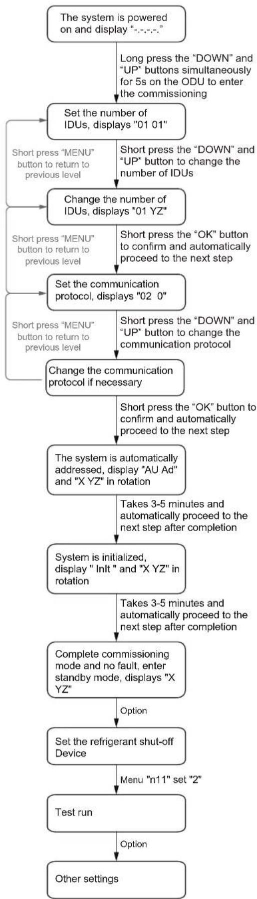
flowchart
graph TD
    A["The system is powered on and display "-.-.-.""] --> B["Long press the "DOWN" and "UP" buttons simultaneously for 5s on the ODU to enter the commissioning"]
    B --> C["Set the number of IDUs, displays "01 01""]
    C --> D["Short press "MENU" button to return to previous level"]
    C --> E["Short press "DOWN" and "UP" button to change the number of IDUs"]
    D --> F["Change the number of IDUs, displays "01 YZ""]
    E --> G["Short press "OK" button to confirm and automatically proceed to the next step"]
    F --> H["Set the communication protocol, displays "02 0""]
    G --> I["Short press "DOWN" and "UP" button to change the communication protocol"]
    H --> J["Change the communication protocol if necessary"]
    I --> K["Short press the "OK" button to confirm and automatically proceed to the next step"]
    J --> L["The system is automatically addressed, display "AU Ad" and "X YZ" in rotation"]
    L --> M["Takes 3-5 minutes and automatically proceed to the next step after completion"]
    M --> N["System is initialized, display "Inlt" and "X YZ" in rotation"]
    N --> O["Takes 3-5 minutes and automatically proceed to the next step after completion"]
    O --> P["Complete commissioning mode and no fault, enter standby mode, displays "X YZ""]
    P --> Q["Option"]
    Q --> R["Set the refrigerant shut-off Device"]
    R --> S["Menu "n11" set "2""]
    S --> T["Test run"]
    T --> U["Option"]
    U --> V["Other settings"]
Figure 8-2
8.6 Rectifications after Test Run is Completed with Exceptions
The test run is considered complete when there is no error code on the user interface or the outdoor unit display. When an error code is displayed, rectify the operation based on the description in the error code table. Try to conduct the test run again to check if the exception has been corrected.
i INFORMATION
Refer to the installation manual of the indoor unit for details on other error codes related to the indoor unit.
8.7 Operating This Unit
Once the installation of this unit is completed, and the test run of the outdoor and indoor units is done, you can start to run the system.
The indoor unit user interface should be connected to facilitate the operations of the indoor unit. Please refer to the installation manual of the indoor unit for more details.
9. PRECAUTIONS ON REFRIGERANT LEAKAGE
The application uses R32 refrigerant which is flammable. So certain essential actions should be taken in time.
The user/owner or their authorized representative shall check the alarm device, mechanical ventilation and refrigerant leakage sensor at least once a year to ensure they are correctly functioning.
Dilution transfer openings (see clause 1.3.1.4 of the owner's manual), for example between rooms, in occupied spaces shall be checked to confirm there are no obstructions that block the free passage of air. A logbook shall be maintained. The results of these checks shall be recorded in the logbook.
Refrigerant leakage sensor shall be set at a percentage (25 % maximum) of the LFL of R32.
Under no circumstances shall potential sources of ignition be used to search for or detect refrigerant leaks. A halide torch (or any other detector using a naked flame) shall not be used.
If leak is suspected, keep the area ventilated to avoid the risk of refrigerant stagnating, and remove/extinguish all naked flames.
If a leakage of refrigerant is found which requires brazing, all of the refrigerant shall be recovered from the system, or isolated (by means of shut off valves) in a part of the system remote from the leak. Oxygen free nitrogen (OFN) shall then be purged through the system both before and during the brazing process.
After the refrigerant leakage maintenance is completed, eliminate the refrigerant leakage error code by remote controller.
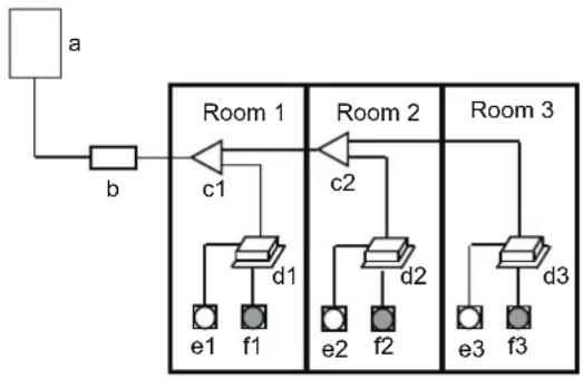
flowchart
graph TD
    a --> b
    b --> Room1
    Room1 -->|c1| Room1a
    Room1 -->|c2| Room2
    Room2 -->|c3| Room3
    Room3 -->|d1| e1
    Room3 -->|d2| e2
    Room3 -->|d3| e3
    e1 --> f1
    e2 --> f2
    e3 --> f3
a: Outdoor unit
b: Refrigerant shut-off device
c: Branch
d: Indoor unit
e: Remote controller
f: Refrigerant leakage sensor
Figure 9-1
CAUTION
- If equipped with a refrigerant leakage sensor for safety, to be effective, the unit must be electrically powered at all times after installation, other than when servicing.
- If equipped with electrically powered safety measures, such as a refrigerant shut-off device, alarm device, mechanical ventilation and so on, to be effective, the unit must be electrically powered at all times after installation, except when servicing.
9.1 Important Information for the Used Refrigerant
This product has fluorinated gas. This gas MAY NOT be released into the air.
Refrigerant type: R32; Value of GWP: 675;
GWP=Global Warming Potential
Table 9-1
| Model | Factory charge | |
| Refrigerant/kg | tonnes CO2 equivalent | |
| 8kW | 2.00 | 1.35 |
| 10kW | 2.00 | 1.35 |
| 12kW | 2.85 | 1.92 |
| 14kW | 2.85 | 1.92 |
| 16kW | 2.85 | 1.92 |
| 18kW | 2.85 | 1.92 |
Attention:
Frequency of Refrigerant Leak Checks
1) For equipment that contains fluorinated greenhouse gases in quantities of 5 tonnes of CO_2 equivalent or more, but of less than 50 tonnes of CO_2 equipment, at least every 12 months, or where a leakage detection system is installed, at least every 24 months.
2) For equipment that contains fluorinated greenhouse gases in quantities of 50 tonnes of CO_2 equivalent or more, but of less than 500 tonnes of CO_2 equipment, at least every six months, or where a leakage detection system is installed, at least every 12 months.
3) For equipment that contains fluorinated greenhouse gases in quantities of 500 tonnes of CO_2 equivalent or more, at least every three months, or where a leakage detection system is installed, at least every six months.
4) Non-hermetically sealed equipment charged with fluorinated greenhouse gases shall only be sold to the end user where evidence is providing that the installation is to be carried out by an undertaking certified person.
5) Only a certificated professional is allowed to do installation, operation and maintenance.
10. TURN OVER TO CUSTOMER
The operation manual of indoor unit and operation manual of outdoor unit must be turned over to the customer. Explain the contents of the operation manual to the customers in detail.
11. TECHNICAL DATA
11.1 Component Layout and Refrigerant Circuits
■ 8-10kW (Single-phase)
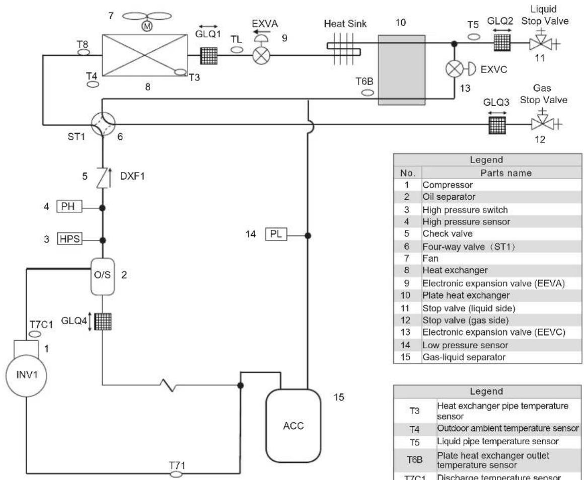
flowchart
graph TD
    A["Heat Sink"] --> B["T5"]
    B --> C["GLQ2"]
    C --> D["Liquid Stop Valve"]
    D --> E["11"]
    E --> F["EXVC"]
    F --> G["13"]
    G --> H["GLQ3"]
    H --> I["12"]
    I --> J["Gas Stop Valve"]
    K["T6B"] --> L["T6B"]
    M["T7C1"] --> N["T7C1"]
    O["INV1"] --> P["T7C1"]
    Q["PH"] --> R["4"]
    S["HPS"] --> T["3"]
    U["DXF1"] --> V["5"]
    W["PL"] --> X["14"]
    Y["OL/S"] --> Z["2"]
    AA["ACC"] --> AB["15"]
    AC["T71"] --> AD["T71"]
    AE["T8"] --> AF["T4"]
    AG["M"] --> AH["T3"]
    AI["TL"] --> AJ["T3"]
    AK["EXVA"] --> AL["T3"]
    AM["T6B"] --> AN["T6B"]
    AO["ST1"] --> AP["6"]
    AQ["PL"] --> AR["14"]
    AS["Legend"] --> AT["No."]
    AS --> AU["Parts name"]
    AT --> AV["1 Compressor"]
    AT --> AW["2 Oil separator"]
    AT --> AX["3 High pressure switch"]
    AT --> AY["4 High pressure sensor"]
    AT --> AZ["5 Check valve"]
    AT --> BA["6 Four-way valve (ST1)"]
    AT --> BB["7 Fan"]
    AT --> BC["8 Heat exchanger"]
    AT --> BD["9 Electronic expansion valve (EEVA)"]
    AT --> BE["10 Plate heat exchanger"]
    AT --> BF["11 Stop valve (liquid side)"]
    AT --> BG["12 Stop valve (gas side)"]
    AT --> BH["13 Electronic expansion valve (EEVC)"]
    AT --> BI["14 Low pressure sensor"]
    AT --> BJ["15 Gas-liquid separator"]
Figure 11-1
Figure 11-2
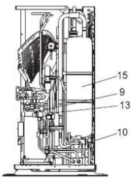
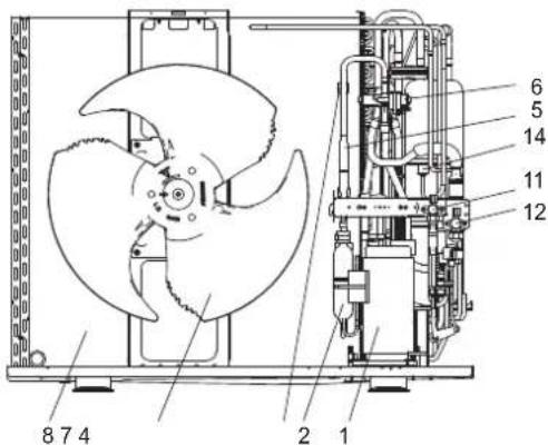
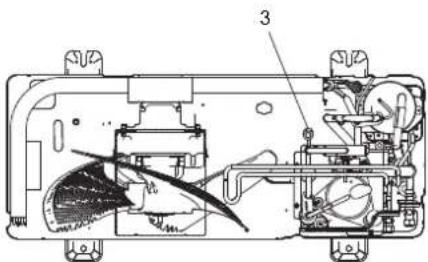
■ 12-18kW (Single-phase)
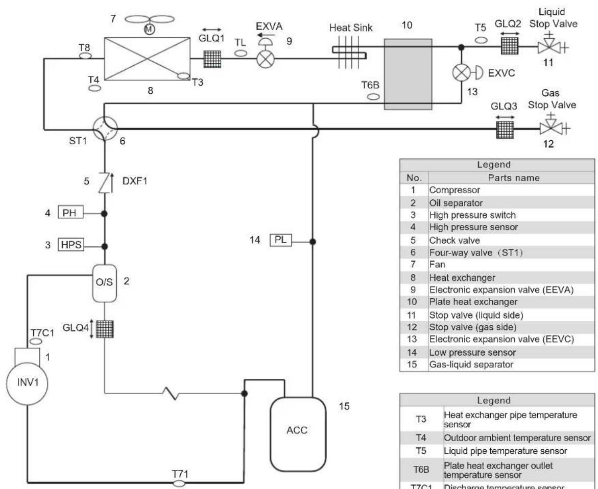
flowchart
graph TD
    A["7"] --> B["GLQ1"]
    B --> C["T3"]
    C --> D["EXVA"]
    D --> E["9"]
    E --> F["Heat Sink"]
    F --> G["10"]
    G --> H["T5"]
    H --> I["GLQ2"]
    I --> J["Liquid Stop Valve"]
    J --> K["11"]
    K --> L["EXVC"]
    L --> M["13"]
    M --> N["GLQ3"]
    N --> O["Gas Stop Valve"]
    O --> P["12"]
    P --> Q["ST1"]
    Q --> R["6"]
    R --> S["5"]
    S --> T["DXF1"]
    T --> U["4 PH"]
    U --> V["3 HPS"]
    V --> W["O/S 2"]
    W --> X["T7C1"]
    X --> Y["INV1"]
    Y --> Z["T71"]
    Z --> AA["ACC"]
    AA --> AB["15"]
    AB --> AC["PL"]
    AC --> AD["14"]
    AD --> AE["T6B"]
    AE --> AF["Heat Sink"]
    AF --> AG["T6B"]
    AG --> AH["Heat Sink"]
    AH --> AI["T6B"]
    AI --> AJ["Heat Sink"]
    AJ --> AK["T6B"]
    AK --> AL["T6B"]
    AL --> AM["T6B"]
    AM --> AN["T6B"]

    style A fill:#f9f,stroke:#333
    style B fill:#ccf,stroke:#333
    style C fill:#cfc,stroke:#333
    style D fill:#fcc,stroke:#333
    style E fill:#cff,stroke:#333
    style F fill:#ffc,stroke:#333
    style G fill:#fcf,stroke:#333
    style H fill:#cff,stroke:#333
    style I fill:#ffc,stroke:#333
    style J fill:#cfc,stroke:#333
    style K fill:#fcc,stroke:#333
    style L fill:#ffc,stroke:#333
    style M fill:#cfc,stroke:#333
    style N fill:#fcc,stroke:#333
    style O fill:#ffc,stroke:#333
    style P fill:#cfc,stroke:#333
    style Q fill:#fcc,stroke:#333
    style R fill:#ffc,stroke:#333
    style S fill:#cfc,stroke:#333
    style T fill:#fcc,stroke:#333
    style U fill:#ffc,stroke:#333
    style V fill:#cfc,stroke:#333
    style W fill:#fcc,stroke:#333
    style X fill:#ffc,stroke:#333
    style Y fill:#cfc,stroke:#333
    style Z fill:#fcc,stroke:#333
    style AA fill:#cfc,stroke:#333
    style AB fill:#cfc,stroke:#333
    style AC fill:#cfc,stroke:#333
    style AD fill:#cfc,stroke:#333
    style AE fill:#cfc,stroke:#333
    style AF fill:#cfc,stroke:#333
    style AG fill:#cfc,stroke:#333
    style AH fill:#cfc,stroke:#333
    style AI fill:#cfc,stroke:#333
    style AJ fill:#cfc,stroke:#333
    style AK fill:#cfc,stroke:#333
Figure 11-3
| Legend | |
| No. | Parts name |
| 1 | Compressor |
| 2 | Oil separator |
| 3 | High pressure switch |
| 4 | High pressure sensor |
| 5 | Check valve |
| 6 | Four-way valve (ST1) |
| 7 | Fan |
| 8 | Heat exchanger |
| 9 | Electronic expansion valve (EEVA) |
| 10 | Plate heat exchanger |
| 11 | Stop valve (liquid side) |
| 12 | Stop valve (gas side) |
| 13 | Electronic expansion valve (EEVC) |
| 14 | Low pressure sensor |
| 15 | Gas-liquid separator |
| Legend | |
| T3 | Heat exchanger pipe temperature sensor |
| T4 | Outdoor ambient temperature sensor |
| T5 | Liquid pipe temperature sensor |
| T6B | Plate heat exchanger outlet temperature sensor |
| T7C1 | Discharge temperature sensor |
| T71 | Suction temperature sensor |
| T8 | Condenser inlet temperature sensor |
| TL | Condenser outlet temperature sensor |
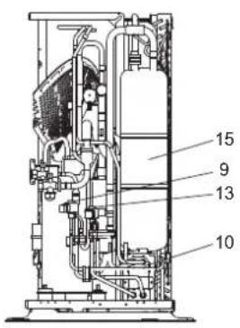
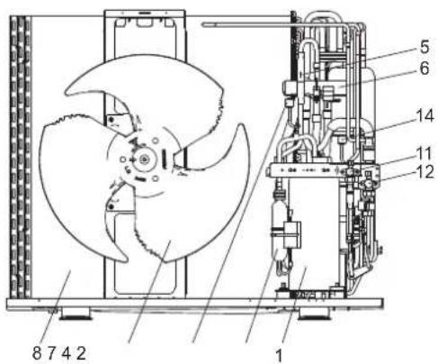
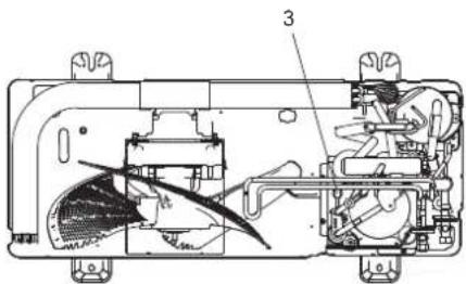
Figure 11-4
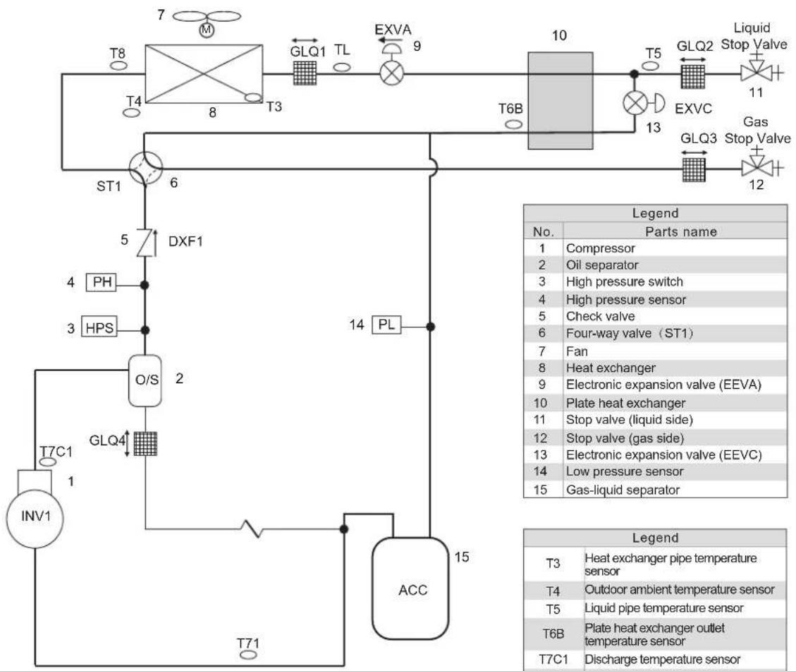
flowchart
graph TD
    A["7 M"] --> B["T4"]
    B --> C["T3"]
    C --> D["T6B"]
    D --> E["T5"]
    E --> F["GLQ2"]
    F --> G["11"]
    G --> H["EXVC"]
    H --> I["13"]
    I --> J["GLQ3"]
    J --> K["12"]
    K --> L["Gas"]
    L --> M["Stop Valve"]
    N["ST1"] --> O["6"]
    P["DXF1"] --> Q["5"]
    R["PH"] --> S["4"]
    T["HPS"] --> U["3"]
    V["O/S"] --> W["2"]
    X["INV1"] --> Y["1"]
    Z["ACC"] --> AA["15"]
    AB["PL"] --> AC["14"]
    AD["T7C1"] --> AE["1"]
    AF["T71"] --> AG["T7C1"]
    AH["Legend"] --> AI["No."]
    AI --> AJ["Parts name"]
    AJ --> AK["1 Compressor"]
    AJ --> AL["2 Oil separator"]
    AJ --> AM["3 High pressure switch"]
    AJ --> AN["4 High pressure sensor"]
    AJ --> AO["5 Check valve"]
    AJ --> AP["6 Four-way valve (ST1)"]
    AJ --> AQ["7 Fan"]
    AJ --> AR["8 Heat exchanger"]
    AJ --> AS["9 Electronic expansion valve (EEVA)"]
    AJ --> AT["10 Plate heat exchanger"]
    AJ --> AU["11 Stop valve (liquid side)"]
    AJ --> AV["12 Stop valve (gas side)"]
    AJ --> AW["13 Electronic expansion valve (EEVC)"]
    AJ --> AX["14 Low pressure sensor"]
    AJ --> AY["15 Gas-liquid separator"]
Figure 11-5
| Legend | |
| No. | Parts name |
| 1 | Compressor |
| 2 | Oil separator |
| 3 | High pressure switch |
| 4 | High pressure sensor |
| 5 | Check valve |
| 6 | Four-way valve (ST1) |
| 7 | Fan |
| 8 | Heat exchanger |
| 9 | Electronic expansion valve (EEVA) |
| 10 | Plate heat exchanger |
| 11 | Stop valve (liquid side) |
| 12 | Stop valve (gas side) |
| 13 | Electronic expansion valve (EEVC) |
| 14 | Low pressure sensor |
| 15 | Gas-liquid separator |
| Legend | |
| T3 | Heat exchanger pipe temperature sensor |
| T4 | Outdoor ambient temperature sensor |
| T5 | Liquid pipe temperature sensor |
| T6B | Plate heat exchanger outlet temperature sensor |
| T7C1 | Discharge temperature sensor |
| T71 | Suction temperature sensor |
| T8 | Condenser inlet temperature sensor |
| TL | Condenser outlet temperature sensor |
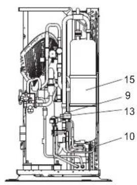
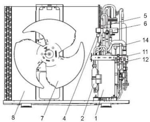
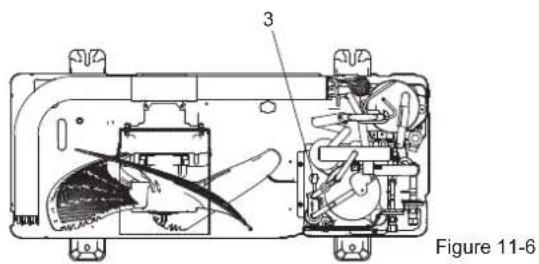
11.2 Fan Performance
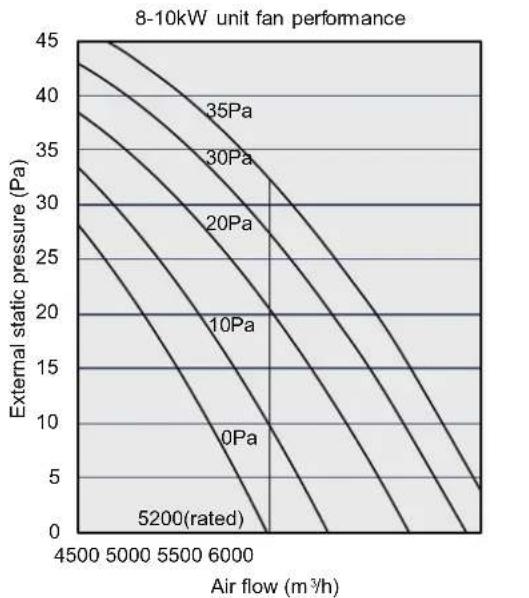
line
| Air flow (m³/h) | External static pressure (Pa) | | --------------- | ----------------------------- | | 4500 | 45 | | 5000 | 40 | | 5500 | 35 | | 6000 | 30 | | 6500 | 25 | | 7000 | 20 | | 7500 | 15 | | 8000 | 10 | | 8500 | 5 | | 9000 | 0 |Figure 11-7
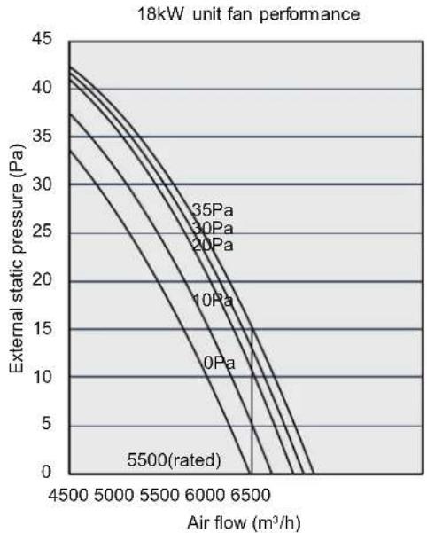
line
| Air flow (m³/h) | External static pressure (Pa) for 0Pa | External static pressure (Pa) for 10Pa | External static pressure (Pa) for 20Pa | External static pressure (Pa) for 30Pa | External static pressure (Pa) for 35Pa | | --------------- | ------------------------------------- | -------------------------------------- | -------------------------------------- | -------------------------------------- | -------------------------------------- | | 4500 | 42 | 41 | 40 | 39 | 38 | | 5000 | 38 | 37 | 36 | 35 | 34 | | 5500 | 32 | 31 | 30 | 29 | 28 | | 6000 | 24 | 23 | 22 | 21 | 20 | | 6500 | 16 | 15 | 14 | 13 | 12 | | 7000 | 8 | 7 | 6 | 5 | 4 | | 7500 | 4 | 3 | 2 | 1 | 0 | | 8000 | 2 | 1 | 0 | 0 | 0 | | 8500 | 1 | 0 | 0 | 0 | 0 | | 9000 | 0 | 0 | 0 | 0 | 0 | | 9500 | 0 | 0 | 0 | 0 | 0 | | 10000 | 0 | 0 | 0 | 0 | 0 | | 10500 | 0 | 0 | 0 | 0 | 0 | | 11000 | 0 | 0 | 0 | 0 | 0 | | 11500 | 0 | 0 | 0 | 0 | 0 | | 12000 | 0 | 0 | 0 | 0 | 0 | | 12500 | 0 | 0 | 0 | 0 | 0 | | 13000 | 0 | 0 | 0 | 0 | 0 | | 13500 | 0 | 0 | 0 | 0 | 0 | | 14000 | 0 | 0 | 0 | 0 | 0 | | 14500 | 0 | 0 | 0 | 0 | 0 | | 15000 | 0 | 0 | 0 | 0 | 0 | | Note: The actual values are not provided in the code. The data is presented in a CSV format with three columns: 'Air flow (m³/h)' and 'External static pressure (Pa)'. The numbers above the bars represent the specific values of the pressure at each air flow level. There is no label for the data series. The rating value '5500(rated)' is noted below the data points. The number '55' is also displayed in the bottom right corner. The label '55' is in the bottom left corner.Figure 11-9
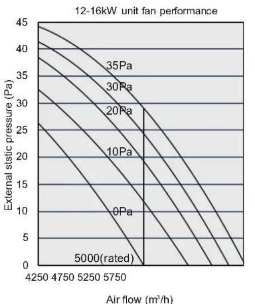
line
| Air flow (m³/h) | External static pressure (Pa) | | --------------- | ----------------------------- | | 4250 | 45 | | 4750 | 40 | | 5250 | 35 | | 5750 | 30 | | 5750 | 25 | | 5750 | 20 | | 5750 | 15 | | 5750 | 10 | | 5750 | 5 | | 5750 | 0 |Figure 11-8
11.3 Erp imformation
MV8M-80WV2N8 T2
| Name or trademark | Factory | |
| Indoor model | 2×MIH15T2*+2×MIH22T2* | |
| Outdoor model | MV8M-80WV2N8 | |
| Harmonized standards | (EU)206/2012+(EU)2016/2282;(EU)No 626/201+(EU)2017/254;EN 14825:2016;EN 14511-3:2013;EN 12102-1:2017 | |
| Specifics precautions | None | |
| Testing conditions | According to harmonized standards | |
| Sound power level at standard rating conditions (indoor/outdoor) | [dB] | 58/68 |
| Refrigerant type | R32 | |
| GWP | [kg CO2, equivalents] | 675 |
| SEER | 5.80 | |
| Energy efficiency class in cooling | A+ | |
| Annual electricity consumption in cooling QCE | [kWh/a] | 434 |
| Design load in cooling mode (Pdesignc) | [kW] | 7.20 |
| SCOP (heating average season) | 3.80 | |
| Energy efficiency class in heating (average season) | A | |
| Annual electricity consumption in heating QHE (average season) | [kWh/a] | 2063 |
| Design load in heating mode (Pdesignh) | [kW] | 5.60 |
| Declared capacity at reference design condition (heating average season) | [kW] | 7.20 |
| Back up heating capacity at reference design condition (heating average season) | [kW] | 0 |
| Refrigerant leakage contributes to climate change. Refrigerant with lower global warming potential (GWP) would contribute less to global warming than a Refrigerant with higher GWP, if leaked to the atmosphere. This appliance contains a Refrigerant fluid with a GWP equal to [675]. This means that if 1kg of this refrigerant fluid would be leaked to the atmosphere, the impact on global warming would be [675] times higher than 1kg of CO2, over a period of 100 years. Never try to interfere with the refrigerant circuit yourself or disassemble the product yourself and always ask a professional. | ||
MV8M-100WV2N8 T2
| Name or trademark | Factory | |
| Indoor model | 3×MIH22T2*+1×MIH28T2* | |
| Outdoor model | MV8M-100WV2N8 | |
| Harmonized standards | (EU)206/2012+(EU)2016/2282;(EU)No 626/201+(EU)2017/254;EN 14825:2016;EN 14511-3:2013;EN 12102-1:2017 | |
| Specifics precautions | None | |
| Testing conditions | According to harmonized standards | |
| Sound power level at standard rating conditions (indoor/outdoor) | [dB] | 58/69 |
| Refrigerant type | R32 | |
| GWP | [kg CO2, equivalents] | 675 |
| SEER | 5.7 | |
| Energy efficiency class in cooling | A+ | |
| Annual electricity consumption in cooling QCE | [kWh/a] | 553 |
| Design load in cooling mode (Pdesignc) | [kW] | 9.00 |
| SCOP (heating average season) | 3.80 | |
| Energy efficiency class in heating (average season) | A | |
| Annual electricity consumption in heating QHE (average season) | [kWh/a] | 2211 |
| Design load in heating mode (Pdesignh) | [kW] | 6.00 |
| Declared capacity at reference design condition (heating average season) | [kW] | 9.00 |
| Back up heating capacity at reference design condition (heating average season) | [kW] | 0 |
| Refrigerant leakage contributes to climate change. Refrigerant with lower global warming potential (GWP) would contribute less to global warming than a Refrigerant with higher GWP, if leaked to the atmosphere. This appliance contains a Refrigerant fluid with a GWP equal to [675]. This means that if 1kg of this refrigerant fluid would be leaked to the atmosphere, the impact on global warming would be [675] times higher than 1kg of CO2, over a period of 100 years. Never try to interfere with the refrigerant circuit yourself or disassemble the product yourself and always ask a professional. | ||
MV8M-80WV2N8 T2
Cooling mode:
| Information requirements for air-to-air conditioners | ||||||||
| Model(s): MV8M-80WV2N8Test matching indoor units form, ducted: 2×MIH15T2*+2×MIH22T2* | ||||||||
| Outdoor side heat exchanger of air conditioner: air | ||||||||
| Indoor side heat exchanger of air conditioner: air | ||||||||
| Type: compressor driven | ||||||||
| Driver of compressor: electric motor | ||||||||
| Item Symbol | Value Unit | Item Symbol | Value Unit | |||||
| Rated cooling capacity | Prated,c 7.20 | kW | Seasonal space cooling energy efficiency | ηs,c 229.0 % | ||||
| Declared cooling capacity for part load at given outdoor temperatures Tj and indoor 27/19°C (dry/wet bulb) | Declared energy efficiency ratio or gas utilisation efficiency /auxiliary energy factor for part load at given outdoor temperatures Tj | |||||||
| Tj=+35°C | Pdc | 7.20 | kW | Tj=+35°C | EERd | 3.70 | -- | |
| Tj=+30°C | Pdc | 5.31 | kW | Tj=+30°C | EERd | 5.47 | -- | |
| Tj=+25°C | Pdc | 3.41 | kW | Tj=+25°C | EERd | 7.65 | -- | |
| Tj=+20°C | Pdc | 2.42 | kW | Tj=+20°C | EERd | 10.06 | -- | |
| Degradation co-efficient for air conditioners(*) | Cdc 0.25 | -- | ||||||
| Power consumption in modes other than "active mode" | ||||||||
| Off mode | POFF | 0.025 | kW | Crankcase heater mode | Pck | 0.002 | kW | |
| Thermosat-off mode | PTO | 0.035 | kW | Standby mode | PSB | 0.025 | kW | |
| Other items | ||||||||
| Capacity control variable | For air-to-air air conditioner: air flow rate, outdoor measured | -- | 5200 | m3/h | ||||
| Sound power level, outdoor | LWA 68 dB | |||||||
| GWP of the refrigerant | 675 | kg CO2 eq (100years) | ||||||
| Contact details | ||||||||
| (*)If Cdc is not determined by measurement, then the default degradation coefficient of heat pumps shall be 0.25. | ||||||||
| Where information relates to multi-split air conditioners, the test result and performance data may be obtained on the basis of performance of the outdoor unit, with a combination of indoor unit(s) recommended by the manufacturer or importer. | ||||||||
MV8M-80WV2N8 T2
Heating mode:
| Information requirements for heat pumps | ||||||||
| Model(s): MV8M-80WV2N8Test matching indoor units form, ducted: 2×MIH15T2*+2×MIH22T2* | ||||||||
| Outdoor side heat exchanger of air conditioner: air | ||||||||
| Indoor side heat exchanger of air conditioner: air | ||||||||
| If the heater is equipped with a supplementary heater: no | ||||||||
| Driver of compressor: electric motor | ||||||||
| Parameters shall be declared for the average heating season, parameters for the warmer and colder heating seasons are optional. | ||||||||
| Item Symbol | Value Unit | Item Symbol | Value Unit | |||||
| Rated heating capacity | Prated,h 7.20 | kW | Seasonal space heating energy efficiency | ηs,h | 149.0 % | |||
| Declared heating capacity for part load at indoor teperature 20°C and outdoor temperatures Tj | Declared coefficient of performance or gas utilisation efficiency/auxiliary energy factor for part load at given outdoor temperatures Tj | |||||||
| Tj=-7°C | Pdh | 4.95 | kW | Tj=-7°C | COPd | 2.46 | -- | |
| Tj=+2°C | Pdh | 3.02 | kW | Tj=+2°C | COPd | 3.83 | -- | |
| Tj=+7°C | Pdh | 2.07 | kW | Tj=+7°C | COPd | 4.59 | -- | |
| Tj=+12°C | Pdh | 2.06 | kW | Tj=+12°C | COPd | 6.31 | -- | |
| Tbiv=bivalent temperature | Pdh 5.60 | kW | Tbiv=bivalent temperature | COPd | 2.31 | -- | ||
| TOL=operation temperature | Pdh | 5.60 | kW | TOL=operation temperature | COPd | 2.31 | -- | |
| Bivalent temperature -10 Tbiv | °C | |||||||
| Degradation co-efficient for heat pumps(**) | Cdh 0.25 | -- | ||||||
| Power consumption in modes other than "active mode" Supplementary heater | ||||||||
| Off mode | POFF | 0.025 | kW | Back-up heating capacity(*) | elbu | 0 | kW | |
| Thermosat-off mode | PTO | 0.035 | kW | Type of energy input | ||||
| Crankcase heater mode | PCK | 0.002 | kW | Standby mode | Psb | 0.025 | kW | |
| Other items | ||||||||
| Capacity control | variable | For air-to-air heat pump: air flow rate, outdoor measured | -- 5200 | m3/h | ||||
| Sound power level,outdoor | LWA 68 dB | |||||||
| GWP of the refrigerant | 675 | kg CO2 eq (100years) | ||||||
| Contact details | ||||||||
| (*) | ||||||||
| (**)If Cdh is not determined by measurement, then the default degradation coefficient of heat pumps shall be 0.25. | ||||||||
| Where information relates to multi-split heat pumps, xthe test result and performance data may be obtained on the basis of performance of the outdoor unit, with a combination of indoor unit(s) recommended by the manufacturer or importer. | ||||||||
MV8M-100WV2N8 T2
Cooling mode:
| Information requirements for air-to-air conditioners | ||||||||
| Model(s): MV8M-100WV2N8Test matching indoor units form, ducted: 3×MIH22T2*+1×MIH28T2* | ||||||||
| Outdoor side heat exchanger of air conditioner: air | ||||||||
| Indoor side heat exchanger of air conditioner: air | ||||||||
| Type: compressor driven | ||||||||
| Driver of compressor: electric motor | ||||||||
| Item Symbol | Value Unit | Item Symbol | Value Unit | Value Unit | ||||
| Rated cooling capacity | Prated,c 9.0 | 0 | kW | Seasonal space cooling energy efficiency | ηs,c 225.0 % | |||
| Declared cooling capacity for part load at given outdoor temperatures Tj and indoor 27/19°C (dry/wet bulb) | Declared energy efficiency ratio or gas utilisation efficiency /auxiliary energy factor for part load at given outdoor temperatures Tj | |||||||
| Tj=+35°C | Pdc | 9.00 | kW | Tj=+35°C | EERd | 3.25 | -- | |
| Tj=+30°C | Pdc | 6.63 | kW | Tj=+30°C | EERd | 4.88 | -- | |
| Tj=+25°C | Pdc | 4.26 | kW | Tj=+25°C | EERd | 7.31 | -- | |
| Tj=+20°C | Pdc | 2.42 | kW | Tj=+20°C | EERd | 10.42 | -- | |
| Degradation co-efficient for air conditioners(*) | Cdc 0.25 | -- | ||||||
| Power consumption in modes other than "active mode" | ||||||||
| Off mode | POFF | 0.025 | kW | Crankcase heater mode | Pck | 0.002 | kW | |
| Thermosat-off mode | PTO | 0.035 | kW | Standby mode | PSB | 0.025 | kW | |
| Other items | ||||||||
| Capacity control variable | For air-to-air air conditioner: air flow rate, outdoor measured | -- | 5200 | m3/h | ||||
| Sound power level, outdoor | LWA 69 dB | |||||||
| GWP of the refrigerant 675 | kg CO2 eq (100years) | |||||||
| Contact details | ||||||||
| (*)If Cdc is not determined by measurement, then the default degradation coefficient of heat pumps shall be 0.25. | ||||||||
| Where information relates to multi-split air conditioners, the test result and performance data may be obtained on the basis of performance of the outdoor unit, with a combination of indoor unit(s) recommended by the manufacturer or importer. | ||||||||
MV8M-100WV2N8 T2
Heating mode:
| Information requirements for heat pumps | ||||||||
| Model(s): MV8M-100WV2N8Test matching indoor units form, ducted: 3×MIH22T2*+1×MIH28T2* | ||||||||
| Outdoor side heat exchanger of air conditioner: air | ||||||||
| Indoor side heat exchanger of air conditioner: air | ||||||||
| If the heater is equipped with a supplementary heater: no | ||||||||
| Driver of compressor: electric motor | ||||||||
| Parameters shall be declared for the average heating season, parameters for the warmer and colder heating seasons are optional. | ||||||||
| Item Symbol | Value Unit | Item Symbol | Value Unit | |||||
| Rated heating capacity | Prated,h 9.00 | kW | Seasonal space heating energy efficiency | ηs,h 149 | 0% | |||
| Declared heating capacity for part load at indoor teperature 20°C and outdoor temperatures Tj | Declared coefficient of performance or gas utilisation efficiency/auxiliary energy factor for part load at given outdoor temperatures Tj | |||||||
| Tj=-7°C | Pdh | 5.31 | kW | Tj=-7°C | COPd | 2.47 | -- | |
| Tj=+2°C | Pdh | 3.23 | kW | Tj=+2°C | COPd | 3.90 | -- | |
| Tj=+7°C | Pdh | 2.13 | kW | Tj=+7°C | COPd | 4.39 | -- | |
| Tj=+12°C | Pdh | 2.26 | kW | Tj=+12°C | COPd | 6.46 | -- | |
| Tbiv=bivalent temperature | Pdh 6.00 | kW | Tbiv =bivalent temperature | COPd | 2.28 | -- | ||
| TOL=operation temperature | Pdh | 6.00 | kW | TOL =operation temperature | COPd | 2.28 | -- | |
| Bivalent temperature -10 Tbiv | °C | |||||||
| Degradation co-efficient for heat pumps(**) | Cdh 0.25 | -- | ||||||
| Power consumption in modes other than "active mode" Supplementary heater | ||||||||
| Off mode | POFF | 0.025 | kW | Back-up heating capacity(*) | elbu | 0 | kW | |
| Thermosat-off mode | PTO | 0.035 | kW | Type of energy input | ||||
| Crankcase heater mode | PCK | 0.002 | kW | Standby mode | PSB | 0.025 | kW | |
| Other items | ||||||||
| Capacity control | variable | For air-to-air heat pump: air flow rate, outdoor measured | -- 5200 | m3/h | ||||
| Sound power level,outdoor | LWA | 69 | dB | |||||
| GWP of the refrigerant | 675 | kg CO2 eq (100years) | ||||||
| Contact details | ||||||||
| (*) | ||||||||
| (**)If Cdh is not determined by measurement, then the default degradation coefficient of heat pumps shall be 0.25. | ||||||||
| Where information relates to multi-split heat pumps, xthe test result and performance data may be obtained on the basis of performance of the outdoor unit, with a combination of indoor unit(s) recommended by the manufacturer or importer. | ||||||||
Cooling mode:
| Information requirements for air-to-air conditioners | ||||||||
| Model(s): MV8M-120WV2N8 / MV8M-120WV2RN8Test matching indoor units form, ducted: 1×MIH15T2*+1×MIH22T2*+2×MIH45T2* | ||||||||
| Outdoor side heat exchanger of air conditioner: air | ||||||||
| Indoor side heat exchanger of air conditioner: air | ||||||||
| Type: compressor driven | ||||||||
| Driver of compressor: electric motor | ||||||||
| Item Symbol | Value Unit | Item Symbol | Value Unit | Value Unit | ||||
| Rated cooling capacity | Prated,c 12 | 30 | kW | Seasonal space cooling energy efficiency | ηs,c 309.0 % | |||
| Declared cooling capacity for part load at given outdoor temperatures Tj and indoor 27/19°C (dry/wet bulb) | Declared energy efficiency ratio or gas utilisation efficiency /auxiliary energy factor for part load at given outdoor temperatures Tj | |||||||
| Tj=+35°C | Pdc | 12.30 | kW | Tj=+35°C | EERd | 3.30 | -- | |
| Tj=+30°C | Pdc | 9.06 | kW | Tj=+30°C | EERd | 5.62 | -- | |
| Tj=+25°C | Pdc | 5.83 | kW | Tj=+25°C | EERd | 9.80 | -- | |
| Tj=+20°C | Pdc | 4.37 | kW | Tj=+20°C | EERd | 13.28 | -- | |
| Degradation co-efficient for air conditioners(*) | Cdc 0.25 | -- | ||||||
| Power consumption in modes other than "active mode" | ||||||||
| Off mode | POFF | 0.005 | kW | Crankcase heater mode | Pck | 0.002 | kW | |
| Thermosat-off mode | PTO | 0.002 | kW | Standby mode | PSB | 0.005 | kW | |
| Other items | ||||||||
| Capacity control variable | For air-to-air air conditioner: air flow rate, outdoor measured | -- | 5000 | m3/h | ||||
| Sound power level, outdoor | LwA 70 dB | |||||||
| GWP of the refrigerant 675 | kg CO2 eq (100years) | |||||||
| Contact details | ||||||||
| (*)If Cdc is not determined by measurement, then the default degradation coefficient of heat pumps shall be 0.25. | ||||||||
| Where information relates to multi-split air conditioners, the test result and performance data may be obtained on the basis of performance of the outdoor unit, with a combination of indoor unit(s) recommended by the manufacturer or importer. | ||||||||
MV8M-120WV2N8 / MV8M-120WV2RN8 T2
Heating mode:
| Information requirements for heat pumps | ||||||||
| Model(s): MV8M-120WV2N8 / MV8M-120WV2RN8Test matching indoor units form, ducted: 1×MIH15T2*+1×MIH22T2*+2×MIH45T2* | ||||||||
| Outdoor side heat exchanger of air conditioner: air | ||||||||
| Indoor side heat exchanger of air conditioner: air | ||||||||
| If the heater is equipped with a supplementary heater: no | ||||||||
| Driver of compressor: electric motor | ||||||||
| Parameters shall be declared for the average heating season, parameters for the warmer and colder heating seasons are optional. | ||||||||
| Item Symbol | Value Unit | Item Symbol | Value Unit | Value Unit | ||||
| Rated heating capacity | Prated,h 12 | 3 | kW | Seasonal space heating energy efficiency | ηs,h 193.0 % | |||
| Declared heating capacity for part load at indoor teperature 20°C and outdoor temperatures Tj | Declared coefficient of performance or gas utilisation efficiency/auxiliary energy factor for part load at given outdoor temperatures Tj | |||||||
| Tj=-7°C | Pdh | 7.43 | kW | Tj=-7°C | COPd | 2.90 | -- | |
| Tj=+2°C | Pdh | 4.52 | kW | Tj=+2°C | COPd | 4.84 | -- | |
| Tj=+7°C | Pdh | 3.02 | kW | Tj=+7°C | COPd | 6.49 | -- | |
| Tj=+12°C | Pdh | 3.36 | kW | Tj=+12°C | COPd | 8.92 | -- | |
| Tbiv=bivalent temperature | Pdh | 8.40 | kW | Tbiv =bivalent temperature | COPd | 2.55 | -- | |
| TOL=operation temperature | Pdh | 8.40 | kW | TOL =operation temperature | COPd | 2.55 | -- | |
| Bivalent temperature -10 Tbiv | °C | |||||||
| Degradation co-efficient for heat pumps(**) | Cdh 0.25 | -- | ||||||
| Power consumption in modes other than "active mode" Supplementary heater | ||||||||
| Off mode | POFF | 0.005 | kW | Back-up heating capacity(*) | elbu | 0 | kW | |
| Thermosat-off mode | PTO | 0.010 | kW | Type of energy input | ||||
| Crankcase heater mode | PCK | 0.002 | kW | Standby mode | Psb | 0.005 | kW | |
| Other items | ||||||||
| Capacity control | variable | For air-to-air heat pump: air flow rate, outdoor measured | -- 5000 | m3/h | ||||
| Sound power level,outdoor | LWA 70 | dB | ||||||
| GWP of the refrigerant | 675 | kg CO2 eq (100years) | ||||||
| Contact details | ||||||||
| (*) | ||||||||
| (**)If Cdh is not determined by measurement, then the default degradation coefficient of heat pumps shall be 0.25. | ||||||||
| Where information relates to multi-split heat pumps, xthe test result and performance data may be obtained on the basis of performance of the outdoor unit, with a combination of indoor unit(s) recommended by the manufacturer or importer. | ||||||||
Cooling mode:
| Information requirements for air-to-air conditioners | ||||||||
| Model(s): MV8M-140WV2N8 / MV8M-140WV2RN8Test matching indoor units form, ducted: 2×MIH28T2*+2×MIH45T2* | ||||||||
| Outdoor side heat exchanger of air conditioner: air | ||||||||
| Indoor side heat exchanger of air conditioner: air | ||||||||
| Type: compressor driven | ||||||||
| Driver of compressor: electric motor | ||||||||
| Item Symbol | Value Unit | Item Symbol | Value Unit | Value Unit | ||||
| Rated cooling capacity | Prated,c 14.00 | kW | Seasonal space cooling energy efficiency | ηs,c 293.0 % | ||||
| Declared cooling capacity for part load at given outdoor temperatures Tj and indoor 27/19°C (dry/wet bulb) | Declared energy efficiency ratio or gas utilisation efficiency /auxiliary energy factor for part load at given outdoor temperatures Tj | |||||||
| Tj=+35°C | Pdc | 14.00 | kW | Tj=+35°C | EERd | 3.00 | -- | |
| Tj=+30°C | Pdc | 10.32 | kW | Tj=+30°C | EERd | 5.07 | -- | |
| Tj=+25°C | Pdc | 6.63 | kW | Tj=+25°C | EERd | 9.27 | -- | |
| Tj=+20°C | Pdc | 4.37 | kW | Tj=+20°C | EERd | 14.13 | -- | |
| Degradation co-efficient for air conditioners(*) | Cdc 0.25 | -- | ||||||
| Power consumption in modes other than "active mode" | ||||||||
| Off mode | POFF | 0.005 | kW | Crankcase heater mode | Pck | 0.002 | kW | |
| Thermosat-off mode | PTO | 0.002 | kW | Standby mode | PSB | 0.005 | kW | |
| Other items | ||||||||
| Capacity control variable | For air-to-air air conditioner: air flow rate, outdoor measured | -- | 5000 | m3/h | ||||
| Sound power level, outdoor | LWA 71 dB | |||||||
| GWP of the refrigerant 675 | kg CO2 eq (100years) | |||||||
| Contact details | ||||||||
| (*)If Cdc is not determined by measurement, then the default degradation coefficient of heat pumps shall be 0.25. | ||||||||
| Where information relates to multi-split air conditioners, the test result and performance data may be obtained on the basis of performance of the outdoor unit, with a combination of indoor unit(s) recommended by the manufacturer or importer. | ||||||||
Heating mode:
| Information requirements for heat pumps | ||||||||
| Model(s): MV8M-140WV2N8 / MV8M-140WV2RN8Test matching indoor units form, ducted: 2×MIH28T2*+2×MIH45T2* | ||||||||
| Outdoor side heat exchanger of air conditioner: air | ||||||||
| Indoor side heat exchanger of air conditioner: air | ||||||||
| If the heater is equipped with a supplementary heater: no | ||||||||
| Driver of compressor: electric motor | ||||||||
| Parameters shall be declared for the average heating season, parameters for the warmer and colder heating seasons are optional. | ||||||||
| Item Symbol | Value Unit | Item Symbol | Value Unit | |||||
| Rated heating capacity | Prated,h 14.0 | kW | Seasonal space heating energy efficiency | ηs,h | 189.0 % | |||
| Declared heating capacity for part load at indoor teperature 20°C and outdoor temperatures Tj | Declared coefficient of performance or gas utilisation efficiency/auxiliary energy factor for part load at given outdoor temperatures Tj | |||||||
| Tj=-7°C | Pdh | 8.58 | kW | Tj=-7°C | COPd | 2.90 | -- | |
| Tj=+2°C | Pdh | 5.22 | kW | Tj=+2°C | COPd | 4.69 | -- | |
| Tj=+7°C | Pdh | 3.56 | kW | Tj=+7°C | COPd | 6.33 | -- | |
| Tj=+12°C | Pdh | 3.43 | kW | Tj=+12°C | COPd | 8.82 | -- | |
| Tbiv=bivalent temperature | Pdh 9.70 | kW | Tbiv=bivalent temperature | COPd | 2.53 | -- | ||
| TOL=operation temperature | Pdh | 9.70 | kW | TOL=operation temperature | COPd | 2.53 | -- | |
| Bivalent temperature -10 Tbiv | °C | |||||||
| Degradation co-efficient for heat pumps(**) | Cdh 0.25 | -- | ||||||
| Power consumption in modes other than "active mode" Supplementary heater | ||||||||
| Off mode | POFF | 0.005 | kW | Back-up heating capacity(*) | elbu | 0 | kW | |
| Thermosat-off mode | PTO | 0.010 | kW | Type of energy input | ||||
| Crankcase heater mode | PCK | 0.002 | kW | Standby mode | PSB | 0.005 | kW | |
| Other items | ||||||||
| Capacity control | variable | For air-to-air heat pump: air flow rate, outdoor measured | -- 5000 | m3/h | ||||
| Sound power level,outdoor | LWA 71 dB | |||||||
| GWP of the refrigerant | 675 | kg CO2 eq (100years) | ||||||
| Contact details | ||||||||
| (*) | ||||||||
| (**)If Cdh is not determined by measurement, then the default degradation coefficient of heat pumps shall be 0.25. | ||||||||
| Where information relates to multi-split heat pumps, xthe test result and performance data may be obtained on the basis of performance of the outdoor unit, with a combination of indoor unit(s) recommended by the manufacturer or importer. | ||||||||
Cooling mode:
| Information requirements for air-to-air conditioners | ||||||||
| Model(s): MV8M-160WV2N8 / MV8M-160WV2RN8Test matching indoor units form, ducted: 1×MIH22T2*+3×MIH45T2* | ||||||||
| Outdoor side heat exchanger of air conditioner: air | ||||||||
| Indoor side heat exchanger of air conditioner: air | ||||||||
| Type: compressor driven | ||||||||
| Driver of compressor: electric motor | ||||||||
| Item Symbol | Value Unit | Item Symbol | Value Unit | Value Unit | ||||
| Rated cooling capacity | Prated,c 15.50 | 50 | kW | Seasonal space cooling energy efficiency | ηs,c 29 | 1.0 % | ||
| Declared cooling capacity for part load at given outdoor temperatures Tj and indoor 27/19°C (dry/wet bulb) | Declared energy efficiency ratio or gas utilisation efficiency /auxiliary energy factor for part load at given outdoor temperatures Ti | |||||||
| Tj=+35°C | Pdc | 15.50 | kW | Tj=+35°C | EERd | 2.90 | -- | |
| Tj=+30°C | Pdc | 11.42 | kW | Tj=+30°C | EERd | 4.89 | -- | |
| Tj=+25°C | Pdc | 7.19 | kW | Tj=+25°C | EERd | 9.28 | -- | |
| Tj=+20°C | Pdc | 4.28 | kW | Tj=+20°C | EERd | 14.96 | -- | |
| Degradation co-efficient for air conditioners(*) | Cdc 0.25 | -- | ||||||
| Power consumption in modes other than "active mode" | ||||||||
| Off mode | POFF | 0.005 | kW | Crankcase heater mode | PCK | 0.002 | kW | |
| Thermosat-off mode | PTO | 0.002 | kW | Standby mode | PSB | 0.005 | kW | |
| Other items | ||||||||
| Capacity control variable | For air-to-air air conditioner: air flow rate, outdoor measured | -- | 5000 | m3/h | ||||
| Sound power level, outdoor | LWA 72 dB | |||||||
| GWP of the refrigerant 675 | kg CO2 eq (100years) | |||||||
| Contact details | ||||||||
| (*)If Cdc is not determined by measurement, then the default degradation coefficient of heat pumps shall be 0.25. | ||||||||
| Where information relates to multi-split air conditioners, the test result and performance data may be obtained on the basis of performance of the outdoor unit, with a combination of indoor unit(s) recommended by the manufacturer or importer. | ||||||||
Heating mode:
| Information requirements for heat pumps | ||||||||
| Model(s): MV8M-160WV2N8 / MV8M-160WV2RN8Test matching indoor units form, ducted: 1×MIH22T2*+3×MIH45T2* | ||||||||
| Outdoor side heat exchanger of air conditioner: air | ||||||||
| Indoor side heat exchanger of air conditioner: air | ||||||||
| If the heater is equipped with a supplementary heater: no | ||||||||
| Driver of compressor: electric motor | ||||||||
| Parameters shall be declared for the average heating season, parameters for the warmer and colder heating seasons are optional. | ||||||||
| Item Symbol | Value Unit | Item Symbol | Value Unit | Value Unit | ||||
| Rated heating capacity | Prated,h 15 | 5 | kW | Seasonal space heating energy efficiency | ηs,h 189 | 0% | ||
| Declared heating capacity for part load at indoor teperature 20°C and outdoor temperatures Tj | Declared coefficient of performance or gas utilisation efficiency/auxiliary energy factor for part load at given outdoor temperatures Tj | |||||||
| Tj=-7°C | Pdh | 9.47 | kW | Tj=-7°C | COPd | 2.88 | -- | |
| Tj=+2°C | Pdh | 5.76 | kW | Tj=+2°C | COPd | 4.69 | -- | |
| Tj=+7°C | Pdh | 3.85 | kW | Tj=+7°C | COPd | 6.36 | -- | |
| Tj=+12°C | Pdh | 3.50 | kW | Tj=+12°C | COPd | 8.98 | -- | |
| Tbiv=bivalent temperature | Pdh 10.70 | kW | Tbiv =bivalent temperature | COPd | 2.46 | -- | ||
| TOL=operation temperature | Pdh | 10.70 | kW | TOL =operation temperature | COPd | 2.46 | -- | |
| Bivalent temperature -10 Tbiv | °C | |||||||
| Degradation co-efficient for heat pumps(**) | Cdh 0.25 | -- | ||||||
| Power consumption in modes other than "active mode" Supplementary heater | ||||||||
| Off mode | POFF | 0.005 | kW | Back-up heating capacity(*) | elbu | 0 | kW | |
| Thermosat-off mode | PTO | 0.010 | kW | Type of energy input | ||||
| Crankcase heater mode | Pck | 0.002 | kW | Standby mode | PSB | 0.005 | kW | |
| Other items | ||||||||
| Capacity control | variable | For air-to-air heat pump: air flow rate, outdoor measured | -- 5000 | m3/h | ||||
| Sound power level,outdoor | LWA 72 | dB | ||||||
| GWP of the refrigerant | 675 | kg CO2 eq (100years) | ||||||
| Contact details | ||||||||
| (*) | ||||||||
| (**)If Cdh is not determined by measurement, then the default degradation coefficient of heat pumps shall be 0.25. | ||||||||
| Where information relates to multi-split heat pumps, xthe test result and performance data may be obtained on the basis of performance of the outdoor unit, with a combination of indoor unit(s) recommended by the manufacturer or importer. | ||||||||
Cooling mode:
| Information requirements for air-to-air conditioners | ||||||||
| Model(s): MV8M-180WV2N8 / MV8M-180WV2RN8Test matching indoor units form, ducted: 4×MIH45T2* | ||||||||
| Outdoor side heat exchanger of air conditioner: air | ||||||||
| Indoor side heat exchanger of air conditioner: air | ||||||||
| Type: compressor driven | ||||||||
| Driver of compressor: electric motor | ||||||||
| Item Symbol | Value Unit | Item Symbol | Value Unit | |||||
| Rated cooling capacity | Prated,c 17. | 50 | kW | Seasonal space cooling energy efficiency | ηs,c 281 | .0 % | ||
| Declared cooling capacity for part load at given outdoor temperatures Tj and indoor 27/19°C (dry/wet bulb) | Declared energy efficiency ratio or gas utilisation efficiency /auxiliary energy factor for part load at given outdoor temperatures Tj | |||||||
| Tj=+35°C | Pdc | 17.50 | kW | Tj=+35°C | EERd | 2.71 | -- | |
| Tj=+30°C | Pdc | 12.63 | kW | Tj=+30°C | EERd | 4.70 | -- | |
| Tj=+25°C | Pdc | 8.15 | kW | Tj=+25°C | EERd | 8.68 | -- | |
| Tj=+20°C | Pdc | 4.41 | kW | Tj=+20°C | EERd | 15.81 | -- | |
| Degradation co-efficient for air conditioners(*) | Cdc 0.25 | -- | ||||||
| Power consumption in modes other than "active mode" | ||||||||
| Off mode | POFF | 0.005 | kW | Crankcase heater mode | PCK | 0.002 | kW | |
| Thermosat-off mode | PTO | 0.002 | kW | Standby mode | PSB | 0.005 | kW | |
| Other items | ||||||||
| Capacity control variable | For air-to-air air conditioner: air flow rate, outdoor measured | -- | 5500 | m3/h | ||||
| Sound power level, outdoor | LWA 73 dB | |||||||
| GWP of the refrigerant 675 | kg CO2 eq (100years) | |||||||
| Contact details | ||||||||
| (*)If Cdc is not determined by measurement, then the default degradation coefficient of heat pumps shall be 0.25. | ||||||||
| Where information relates to multi-split air conditioners, the test result and performance data may be obtained on the basis of performance of the outdoor unit, with a combination of indoor unit(s) recommended by the manufacturer or importer. | ||||||||
Heating mode:
| Information requirements for heat pumps | ||||||||
| Model(s): MV8M-180WV2N8 / MV8M-180WV2RN8Test matching indoor units form, ducted: 4×MIH45T2* | ||||||||
| Outdoor side heat exchanger of air conditioner: air | ||||||||
| Indoor side heat exchanger of air conditioner: air | ||||||||
| If the heater is equipped with a supplementary heater: no | ||||||||
| Driver of compressor: electric motor | ||||||||
| Parameters shall be declared for the average heating season, parameters for the warmer and colder heating seasons are optional. | ||||||||
| Item Symbol | Value Unit | Item Symbol | Value Unit | |||||
| Rated heating capacity | Prated,h 17 | 50 | kW | Seasonal space heating energy efficiency | ηs,h 189 | 0 % | ||
| Declared heating capacity for part load at indoor teperature 20°C and outdoor temperatures Tj | Declared coefficient of performance or gas utilisation efficiency/auxiliary energy factor for part load at given outdoor temperatures Tj | |||||||
| Tj=-7°C | Pdh | 9.73 | kW | Tj=-7°C | COPd | 2.77 | -- | |
| Tj=+2°C | Pdh | 5.92 | kW | Tj=+2°C | COPd | 4.64 | -- | |
| Tj=+7°C | Pdh | 4.02 | kW | Tj=+7°C | COPd | 6.68 | -- | |
| Tj=+12°C | Pdh | 3.61 | kW | Tj=+12°C | COPd | 9.33 | -- | |
| Tbiv=bivalent temperature | Pdh 11.00 | kW | Tbiv =bivalent temperature | COPd | 2.34 | -- | ||
| TOL=operation temperature | Pdh | 11.00 | kW | TOL =operation temperature | COPd | 2.34 | -- | |
| Bivalent temperature -10 Tbiv | °C | |||||||
| Degradation co-efficient for heat pumps(**) | Cdh 0.25 | -- | ||||||
| Power consumption in modes other than "active mode" Supplementary heater | ||||||||
| Off mode | POFF | 0.005 | kW | Back-up heating capacity(*) | elbu | 0 | kW | |
| Thermosat-off mode | PTO | 0.010 | kW | Type of energy input | ||||
| Crankcase heater mode | PCK | 0.002 | kW | Standby mode | Pss | 0.005 | kW | |
| Other items | ||||||||
| Capacity control | variable | For air-to-air heat pump: air flow rate, outdoor measured | -- 5500 | m3/h | ||||
| Sound power level,outdoor | LWA | 73 | dB | |||||
| GWP of the refrigerant | 675 | kg CO2 eq (100years) | ||||||
| Contact details | ||||||||
| (*) | ||||||||
| (**)If Cdh is not determined by measurement, then the default degradation coefficient of heat pumps shall be 0.25. | ||||||||
| Where information relates to multi-split heat pumps, xthe test result and performance data may be obtained on the basis of performance of the outdoor unit, with a combination of indoor unit(s) recommended by the manufacturer or importer. | ||||||||
| Fan Types | Axial fan | ||
| Directive (or Standard) for Regulation ErP Directive 2009/125/ECCOMMISSION REGULATION (EU) No 327/2011 | |||
| Model Name ZKSN-200-10-4L+ZL-580*200*12-3N Rev. | |||
| Prepare by | |||
Specified Information of Fan:
| No. | Information Item Comment | |
| 1 | _target = | 29.41% |
| 2 | Overall efficiency ( _e ) = | 33.44% |
| 3 | Pass or not (Criteria: _e ≥slant _target ) | Pass |
| 4 | Measurement category (A-D) A | |
| 5 | Efficiency category (static or total) Static | |
| 6 | Efficiency grade at optimum energy efficiency point N =42.6 | |
| 7 | VSD is integrated within the fan YES | |
| 8 | Year of Manufacture Ref. to the Unit Nameplate | |
| 9 | Manufacturer's name and place of manufacture Ref. to the Unit Nameplate | |
| 10.1 | Rated motor power input(s) (kW), at optimum energy efficiency | 0.211 |
| 10.2 | Flow rate(s) at optimum energy efficiency ( m^3/h ) | 4891 |
| 10.3 | Pressure(s) at optimum energy efficiency (Pa) | 50 |
| 11 | Rotations per minute (R.P.M) at the optimum energy efficiency point | 800r/min |
| 12 | Specific ratio | 1.001 |
| 13 | Information relevant for facilitating disassembly, recycling or disposal at end-of-life | all materials can be recycled |
| 14 | Information relevant to minimize impact on the environment and ensure optimal life expectancy as regards installation, use and maintenance of the fan | For installation, the clearance of 500 mm shall be kept from inlet |
| 15 | Description of additional items used when determining the fan energy efficiency, such as ducts, that are not described in the measurement category and not supplied with the fan. | Measurement category A, fan is free inlet and outlet conditions |
| 16 | Motor manufacturer | GUANGDONG WELLING MOTOR MANUFACTURING CO.,LTD. |
| Fan Types | Axial fan | ||
| Directive (or Standard) for Regulation ErP Directive 2009/125/ECCOMMISSION REGULATION (EU) No 327/2011 | |||
| Model Name ZKSN | -200-10-4L+ZL-580*200*12-3N Rev. | ||
| Prepare by | |||
Specified Information of Fan:
| No. | Information Item Comment | |
| 1 | _target = | 29.23% |
| 2 | Overall efficiency ( _e ) = | 36.14% |
| 3 | Pass or not (Criteria: _e ≥slant _target ) | Pass |
| 4 | Measurement category (A-D) A | |
| 5 | Efficiency category (static or total) Static | |
| 6 | Efficiency grade at optimum energy efficiency point N = 45.3 | |
| 7 | VSD is integrated within the fan YES | |
| 8 | Year of Manufacture Ref. to the Unit Nameplate | |
| 9 | Manufacturer's name and place of manufacture Ref. to the Unit Nameplate | |
| 10.1 | Rated motor power input(s) (kW), at optimum energy efficiency | 0.198 |
| 10.2 | Flow rate(s) at optimum energy efficiency ( m^3/h ) | 4886 |
| 10.3 | Pressure(s) at optimum energy efficiency (Pa) | 50 |
| 11 | Rotations per minute (R.P.M) at the optimum energy efficiency point | 800r/min |
| 12 | Specific ratio | 1.001 |
| 13 | Information relevant for facilitating disassembly, recycling or disposal at end-of-life | all materials can be recycled |
| 14 | Information relevant to minimize impact on the environment and ensure optimal life expectancy as regards installation, use and maintenance of the fan | For installation, the clearance of 500 mm shall be kept from inlet |
| 15 | Description of additional items used when determining the fan energy efficiency, such as ducts, that are not described in the measurement category and not supplied with the fan. | Measurement category A, fan is free inlet and outlet conditions |
| 16 | Motor manufacturer | Jiangsu Shangqi Group Co., Ltd. |
| Fan Types | Axial fan | ||
| Directive (or Standard) for Regulation ErP Directive 2009/125/ECCOMMISSION REGULATION (EU) No 327/2011 | |||
| Model Name ZKSN | -200-10-3L+ZL-580*200*12-3N Rev. | ||
| Prepare by | |||
Specified Information of Fan:
| No. | Information Item Comment | |
| 1 | _target = | 30.26% |
| 2 | Overall efficiency ( _e ) = | 33.39% |
| 3 | Pass or not (Criteria: _e ≥slant _target ) | Pass |
| 4 | Measurement category (A-D) A | |
| 5 | Efficiency category (static or total) Static | |
| 6 | Efficiency grade at optimum energy efficiency point N = 42.1 | |
| 7 | VSD is integrated within the fan YES | |
| 8 | Year of Manufacture Ref. to the Unit Nameplate | |
| 9 | Manufacturer's name and place of manufacture Ref. to the Unit Nameplate | |
| 10.1 | Rated motor power input(s) (kW), at optimum energy efficiency | 0.288 |
| 10.2 | Flow rate(s) at optimum energy efficiency ( m^3/h ) | 5615 |
| 10.3 | Pressure(s) at optimum energy efficiency (Pa) | 60 |
| 11 | Rotations per minute (R.P.M) at the optimum energy efficiency point | 900r/min |
| 12 | Specific ratio | 1.001 |
| 13 | Information relevant for facilitating disassembly, recycling or disposal at end-of-life | all materials can be recycled |
| 14 | Information relevant to minimize impact on the environment and ensure optimal life expectancy as regards installation, use and maintenance of the fan | For installation, the clearance of 500 mm shall be kept from inlet |
| 15 | Description of additional items used when determining the fan energy efficiency, such as ducts, that are not described in the measurement category and not supplied with the fan. | Measurement category A, fan is free inlet and outlet conditions |
| 16 | Motor manufacturer | GUANGDONG WELLING MOTOR MANUFACTURING CO.,LTD. |
| Fan Types Axial fan | |||
| Directive (or Standard) for Regulation ErP Directive 2009/125/ECCOMMISSION REGULATION (EU) No 327/2011 | |||
| Model Name ZKSN-200-10-3L+ZL-580*200*12-3N Rev. | |||
| Prepare by | |||
Specified Information of Fan:
| No. | Information Item Comment | |
| 1 | _target = | 30.32% |
| 2 | Overall efficiency ( _e ) = | 35.31% |
| 3 | Pass or not (Criteria: _e ≥slant _target ) | Pass |
| 4 | Measurement category (A-D) A | |
| 5 | Efficiency category (static or total) Static | |
| 6 | Efficiency grade at optimum energy efficiency point N = 43.3 | |
| 7 | VSD is integrated within the fan YES | |
| 8 | Year of Manufacture Ref. to the Unit Nameplate | |
| 9 | Manufacturer's name and place of manufacture Ref. to the Unit Nameplate | |
| 10.1 | Rated motor power input(s) (kW), at optimum energy efficiency | 0.294 |
| 10.2 | Flow rate(s) at optimum energy efficiency ( m^3/h ) | 5448 |
| 10.3 | Pressure(s) at optimum energy efficiency (Pa) | 65 |
| 11 | Rotations per minute (R.P.M) at the optimum energy efficiency point | 900r/min |
| 12 | Specific ratio | 1.001 |
| 13 | Information relevant for facilitating disassembly, recycling or disposal at end-of-life | all materials can be recycled |
| 14 | Information relevant to minimize impact on the environment and ensure optimal life expectancy as regards installation, use and maintenance of the fan | For installation, the clearance of 500 mm shall be kept from inlet |
| 15 | Description of additional items used when determining the fan energy efficiency, such as ducts, that are not described in the measurement category and not supplied with the fan. | Measurement category A, fan is free inlet and outlet conditions |
| 16 | Motor manufacturer | Jiangsu Shangqi Group Co., Ltd. |

natural_image
Pure geometric shape with no text, numbers, or symbols
Multi-languages
印刷技术要求

- INSTALLATION AND OWNER'S MANUAL
- IMPORTANT NOTE:
- CONTENTS
- OWNER'S MANUAL 01
- INSTALLATION MANUAL 25
- NOTE
- OWNER'S MANUAL
- BEFORE OPERATING
- i INFORMATION
- WARNING
- Overview
- CAUTION
- Important Safety Information
- Instructions for Application Using R32 Refrigerant
- System layout requirements
- Unit installation requirements
- Piping installation requirements
- Refrigerant charge and room area limitations (strategy 1)
- As shown above:
- Refrigerant charge and room area limitations (strategy 2)
- OPERATIONS
- Operating Range
- Operation and Performance
- Operating System
- Run
- Stop
- Adjust
- Cooling and heating operations
- Features of heating operation
- About heating capacity
- Defrost operation
- Power cuts
- Mishandling in operation
- Protective feature
- Protective equipment
- Cooling
- Heating
- MAINTENANCE AND REPAIR
- Maintenance After the Unit Has Been Shut Down for a Long Period
- About the Refrigerant
- After-sales Service and Warranty
- Warranty period
- Shorter Maintenance and Replacement Cycle
- TROUBLESHOOTING
- Air Conditioner Troubles and Their Causes
- Troubles and Causes of Remote Controller
- Error Code: Overview
- Fault Symptom: Non Air Conditioning Issues
- Symptom 1: The system does not operate
- Symptom 2: The system switches into the fan mode during cooling
- Symptom 3: White mist comes out of a unit
- Symptom 4: Noise of air conditioners cooling
- Symptom 5: Dust comes out of the unit
- Symptom 6: The units give off odors
- Symptom 7: The outdoor unit fan does not spin.
- CHANGING INSTALLATION SITE
- DISPOSAL
- INSTALLATION MANUAL
- PRECAUTIONS
- THIS AIR CONDITIONER ADOPTS THE NEW HFC REFRIGERANT(R32) WHICH DOES NOT DESTROY THE OZONE LAYER.
- Be sure to provide grounding.
- Conform to the regulations of the local electric company when
- Required tools for installation work
- PACKING BOX
- Delivery and Moving
- Delivery
- Moving
- Attached Fittings
- OUTDOOR UNIT
- Outdoor Unit Combination Ratio
- Outdoor unit Stop Valve Size
- PREPARATIONS BEFORE INSTALLATION
- Choosing and Preparing the Installation Site
- Site requirements
- Installation space (Unit: mm)
- Selecting and Preparing the Refrigerant Piping
- Refrigerant piping requirements
- Design considerations
- Allowable length and height difference for refrigerant piping
- Refrigerant pipe selection
- OUTDOOR UNIT INSTALLATION
- Preparing the Structure for Installation
- Things to Note When Connecting the Refrigerant Piping
- Refrigerant Piping Connection
- Leak Detection
- Heat Insulation
- Airtight Test
- Air Purge with Vacuum Pump
- Refrigerant Amount to be Added
- Calculating additional refrigerant charge
- ELECTRICAL WIRING
- Safety Device Requirements
- Abbreviations:
- Connecting the Power Cord
- Connecting the Communication Wiring
- CONFIGURATION
- Overview
- INFORMATION
- Digital Display and Button Settings
- Digital display output
- Function of buttons SW3 to SW6
- Menu mode
- UP/DOWN system check button
- COMMISSIONING
- Overview
- Things to Note During the Test Run
- Checklist Before Test Run
- About Test Run
- Test Run Implementation
- Specific procedures for the test run are as follows:
- Step 1: Power on
- Step 2: Enter commissioning mode
- Step 3: Set the number of IDUs in a system
- Step 4: Select the system communication protocol
- Step 5: IDUs and ODU address setting
- Step 6: System initialization
- Step 7: Ending commissioning mode
- Step 8: Set the refrigerant shut-off device
- Step 9: Test run
- Step 10: Other settings
- Rectifications after Test Run is Completed with Exceptions
- Operating This Unit
- PRECAUTIONS ON REFRIGERANT LEAKAGE
- Important Information for the Used Refrigerant
- Attention:
- Frequency of Refrigerant Leak Checks
- TURN OVER TO CUSTOMER
- TECHNICAL DATA
- Component Layout and Refrigerant Circuits
- Fan Performance
- Erp imformation
- MV8M-80WV2N8 T2
- MV8M-100WV2N8 T2
- MV8M-120WV2N8 / MV8M-120WV2RN8 T2
Brand : MIDEA
Model : MV8M-140WV2RN8
Category : Heat pump