
MURELLE.HT - Water heaters SIME - Free user manual and instructions
Find the device manual for free MURELLE.HT SIME in PDF.


| Product Type | Wall-mounted gas water heater and hot water tank |
| Brand | SIME |
| Model | MURELLE.HT |
| Energy Source | Natural gas or LPG |
| Thermal Power (kW) | 24 - 30 kW |
| Hot Water Flow Rate (ΔT=30°C) | 12 - 16 L/min |
| Dimensions (H × W × D) | 700 × 400 × 300 mm |
| Weight (net) | 28 kg |
| Water Tank Capacity | 40 L |
| Max Water Temperature | 65°C |
| Main Functions | Instantaneous hot water, tank storage, anti-legionella cycle, frost protection |
| Safety Features | Flame failure device, overheat protection, safety valve, gas pressure regulator |
| Control Type | Electronic with digital display |
| Ignition | Automatic electronic ignition |
| Flue Type | Room-sealed (balanced flue) |
| Energy Efficiency Class | A (according to EU regulations) |
| Noise Level (dB) | < 45 dB |
| Maintenance | Annual servicing recommended; clean burner and heat exchanger |
| Spare Parts | Available from authorized SIME dealers; includes thermocouple, gas valve, pump, fan |
| Repairability | Modular design for easy component replacement |
| Warranty | 2 years standard (extended options available) |
| Certifications | CE, ISO 9001 |
Frequently Asked Questions - MURELLE.HT SIME
User questions about MURELLE.HT SIME
0 question about this device. Answer the ones you know or ask your own.
Ask a new question about this device
Download the instructions for your Water heaters in PDF format for free! Find your manual MURELLE.HT - SIME and take your electronic device back in hand. On this page are published all the documents necessary for the use of your device. MURELLE.HT by SIME.
USER MANUAL MURELLE.HT SIME
USER, INSTALLATION AND SERVICING INSTRUCTIONS
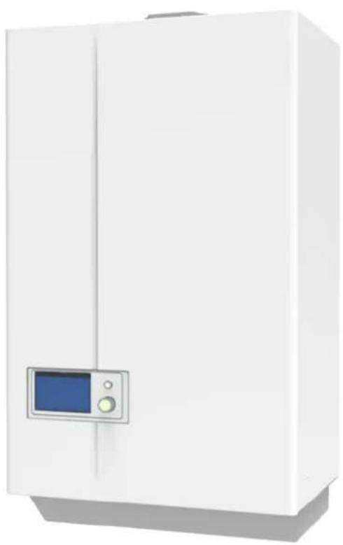
natural_image
White industrial cabinet with a digital display panel on the front panel (no visible text or symbols)EN
To consult the documentation, visit our website www.sime.it

Fonderie SIME S.p.A.
6330337B - 10/2023 - R11
RANGE RATED CERTIFICATION
The maximum power, in heating mode, of MURELLE.HT boilers can be adapted, during the installation, to the thermal needs of the system by modifying the setting of PAR 19 in the 0 .. 100 range.
The setting of PAR 19 = 100 is the factory setting that allows the boiler to deliver its maximum power in heating mode. It can be reduced by modifying the setting of PAR 19 as shown in the table appearing below.
Once the new setting of PAR 19 has been made, the reduced maximum power value (kW) MUST MANDATORILY be applied beside the boiler's data plate. For checks and adjustments after the modification, refer to the new value for the maximum power.
The useful nominal power levels used are those relative to the operating conditions (80-60°C) (Pn min - Pn max).
Example for MURELLE.HT 25 boiler:
- default heating power range: 1,65 - 24,2 setting of PAR 19 = 100
- "reduced" heating power range: 1,65 - 19,7 setting PAR 19 = 80
| DESCRIPTION | MURELLE.HT | |||||||
| 25 30 35 | Setting of PAR 19 | |||||||
| Min Max | Min Max | Min Max | ||||||
| A - Factory power range (heating) kW 1,65 24,2 1,93 29,1 | 2,33 33,9 | 100 | ||||||
| B - Reduced power ranges for maximum power reduction (heating) | kW | 1,65 21,9 | 1,93 26,4 | 2,33 30,7 | 90 | |||
| kW | 1,65 19,7 | 1,93 23,7 | 2,33 27,6 | 80 | ||||
| kW | 1,65 17,4 | 1,93 20,9 | 2,33 24,4 | 70 | ||||
| kW | 1,65 15,2 | 1,93 18,2 | 2,33 21,3 | 60 | ||||
| kW | 1,65 12,9 | 1,93 15,5 | 2,33 18,1 | 50 | ||||
| kW | 1,65 10,7 | 1,93 12,8 | 2,33 15,0 | 40 | ||||
Boiler technical data plate
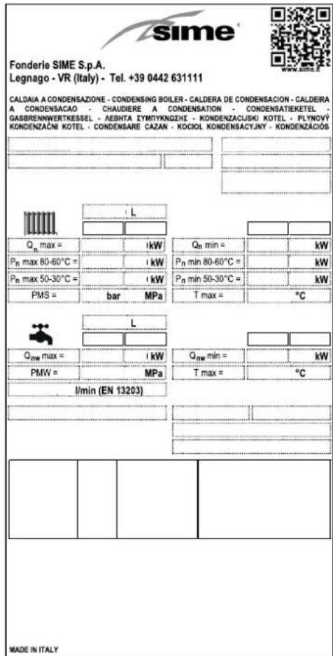

CAUTION
The grey fields must be filled in by the installer.
Range Rated label
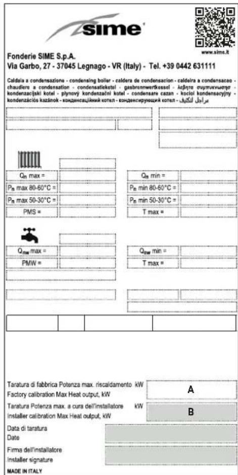
A Factory power range
B Reduced power range for maximum power reduction

WARNINGS
- After having removed the packaging make sure that the product supplied is integral and complete in all its parts. If this is not the case, please contact the Dealer who sold the appliance.
- The appliance must be used as intended by Sime who is not responsible for any damage caused to persons, animals or things, improper installation, adjustment, maintenance and improper use of the appliance.
- In the event of water leaks, disconnect the appliance from the mains power supply, close the water mains and promptly inform professionally qualified personnel.
- Periodically check that the operating pressure of the water heating system when cold is 1-1.2 bar. If this is not the case, increase the pressure or contact professionally qualified personnel.
- If the appliance is not used for a long period of time, at least one of the following operations must be carried out: -set the main system switch to "OFF"; -close the gas and water valves for the water heating system.
- In order to ensure optimal appliance operations Sime recommends that maintenance and checks are carried out ONCE A YEAR.
- If the power cable is damaged, replace it with a cable ordered as a spare part with the same characteristics (type X). Assembly must be by carried out by a qualified professional.

WARNINGS
- It is recommended that all operators read this manual carefully in order to use the appliance in a safe and rational manner.
- This manual is an integral part of the appliance. It must therefore be kept for future reference and must always accompany the appliance in the event the appliance is transferred or sold to another Owner or User or is installed on another system.
- Installation and maintenance of this appliance must be carried out by a qualified company or by a professionally qualified technician in accordance with the instructions contained in the manual. Once the work is complete, the company or technician will issue a declaration of conformity with national and local technical standards and legislation in force in the country where the appliance will be used.
- Any repairs on the appliance must be carried out solely by professionally qualified personnel, using original spare parts only. Failure to comply with these instructions can jeopardise the appliance's safety and void the warranty with immediate effect.
- Fonderie SIME S.p.A. reserves the right to make improvements to its products at any time without prior notice, without compromising their essential characteristics. The graphic illustrations and/or images in this document may show optional accessories that vary according to the country in which the appliance is used.

IT IS FORBIDDEN
- To allow children under the age of 8 to use the appliance. The appliance can be used by children no younger than 8 years old, by people with physical or cognitive disabilities, and by people lacking experience or the necessary knowledge, provided that they are supervised or have been instructed on how to use the appliance safely and that they understand the risks associated with it.
- To allow children to play with the appliance.
- To allow unsupervised children to perform user maintenance and cleaning.
-
To use electrical devices or appliances such as switches, electrical appliances etc if you can smell fuel. If this should happen:
-
open the doors and windows to air the room;
- close the gas isolation device;
-promptly call for professional assistance.
- To touch the appliance with bare feet or with any wet part of the body.
- To carry out any technical intervention or cleaning operation before having disconnected the appliance from the mains power by setting the main switch to "OFF", and closing the gas supply.
- To modify the safety or adjustment devices without authorization and instructions from the manufacturer.

IT IS FORBIDDEN
- To block the condensate drain (if present).
- To pull, detach or twist the electrical cables coming out of the appliance even if the appliance is disconnected from the mains power supply.
- To expose the boiler to atmospheric agents. These boilers can also be installed in partially covered areas, as per EN 15502, with a maximum ambient temperature of 60^ and a minimum ambient temperature of -5^ . It is recommended that the boiler is installed below weathered roofs, on the balcony or in a protected niche, to protect it from exposure to weathering agents (rain, hail and snow). The boiler is equipped as standard with an anti-freeze function.
- To block or reduce the size of the ventilation openings of the room where the appliance is installed, if present.
- Remove the mains power and gas supply from the appliance if the external temperature could fall below ZERO (risk of freezing).
- To leave containers with flammable substances in the room where the appliance is installed.
- To dispose of the packaging material irresponsibly as it could be dangerous. Packaging must be disposed of as specified by the legislation in force in the country where the appliance will be used.
RANGE
| MODEL CODE | |
| MURELLE.HT 25 [MET] 8115101 | |
| MURELLE.HT 25 [GPL] 8115106 | |
| MURELLE.HT 30 [MET] 8115102 | |
| MURELLE.HT 30 [GPL] 8115107 | |
| MURELLE.HT 35 [MET] 8115103 | |
| MURELLE.HT 35 [GPL] 8115108 |
COMPLIANCE
Our company declares that MURELLE.HT boilers comply with the following directives:
– Gas Appliances EU Regulation 2016/426
- Boiler Efficiency Directive 92/42/EEC
– Low Voltage Directive 2014/35/EU
– Electromagnetic Compatibility Directive 2014/30/EU
- Ecodesign Directive 2009/125/EC
– Regulation (EU) No. 811/2013 - 813/2013
- Energy labelling Regulation (EU) No. 2017/1369

Please refer to the technical data plate for the serial number and year of manufacture.
SYMBOLS

WARNING
To indicate actions which, if not carried out correctly, can result in injury of a general nature or may damage or cause the appliance to malfunction; these actions therefore require particular caution and adequate preparation.

ELECTRICAL HAZARD
To indicate actions which, if not carried out correctly, could lead to injury of an electrical nature; these actions therefore require particular caution and adequate preparation.

IT IS FORBIDDEN
To indicate actions which MUST NOT BE carried out.

CAUTION
To indicate particularly important and useful information.
MANUAL STRUCTURE
This manual is organized as follows.
USER INSTRUCTIONS
TABLE OF CONTENTS 7
DESCRIPTION OF THE APPLIANCE
TABLE OF CONTENTS 15
INSTALLATION AND SERVICING INSTRUCTIONS
TABLE OF CONTENTS 25
USER INSTRUCTIONS
TABLE OF CONTENTS
1 USING THE BOILER MURELLE.HT 8
1.1 Control panel 8
1.2 Start-up 9
1.2.1 Preliminary checks....9
1.2.2 Ignition....9
1.3 Settings using the MODE function ..... 10
1.3.1 Domestic hot water 10
1.3.2 DHW 3-star function.... 10
1.3.3 Heating 11
1.4 Fault warnings 12
1.5 Time Programming 12
2 SHUTDOWN 13
2.1 Temporary shutdown....13
2.2 Shutting down for long periods ..... 13
2.1 Temporary shutdown.... 13 2.2 Shutting down for long periods.... 13
3 MAINTENANCE 14
3.1 Adjustments.....14
3.2 External cleaning....14
3.2.1 Cleaning the cladding.... 14
4 DISPOSAL 14
4.1 Disposal of the equipment (European Directive 2012/19/EU) 14
1 USING THE BOILER MURELLE.HT
1.1 Control panel
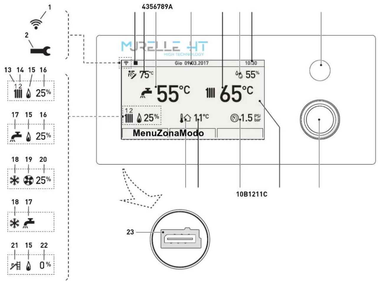
Fig. 1
A "ESC" button: go back to the previous screen
LOCKOUT NOTIFICATION: when the boiler is locked, the button lights up red
B MULTI-FUNCTION ENCODER: turn to navigate the menu, press to confirm the selection
C DISPLAY
1 WiFi
2 Alarm symbol
3 Remote control, where relevant
4 Solar manifold temperature
5 DHW temperature
6 Date
7 Boiler delivery temperature
8 Room humidity level
9 Time
10 System pressure
11 Measured outdoor temperature
12 Presence of external sensor (SE)
13 Heating circuit "1" heat request active
14 Heating circuit "2" heat request active
15 Burner active
16 Burner modulation percentage
17 Domestic hot water circuit heat request active
18 Heat pump request in cold mode active
19 Heat pump active
20 Heat pump modulation percentage
21 Chimney sweep function active
22 Chimney sweep function modulation percentage
23 Programming connector

CAUTION
Remove the protective film on the display after the appliance is used for the first time.
1.2 Start-up
1.2.1 Preliminary checks

WARNING
- Should it be necessary to access the areas in the bottom part of the appliance, make sure that the system components and pipes are not hot (risk of burning).
- Before replenishing the heating system, put on protective gloves.
Commissioning of the MURELLE.HT boiler must be carried out by professionally qualified Personnel after which the boiler can operate automatically. It may however be necessary for the User to start the appliance autonomously without involving a technician: for example, after a holiday. In these cases certain checks and the following operations must be carried:
- check that the gas isolation and water system valves are open
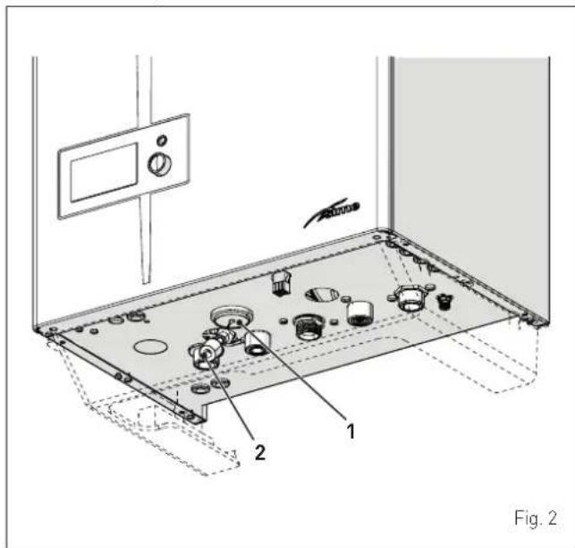
- using a pressure gauge (1), check that the heating system pressure when cold is 1-1.2 bar. If this is not the case, open the filling valve (2) and restore the heating system pressure until the pressure gauge (1) shows a reading of 1-1.2 bar
- close the filling valve (2).
1.2.2 Ignition
After having carried out the preliminary checks, perform the following to start the boiler:
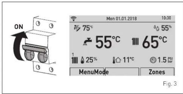
- set the main system switch to "ON"
- after a few seconds, the "Main screen" is shown
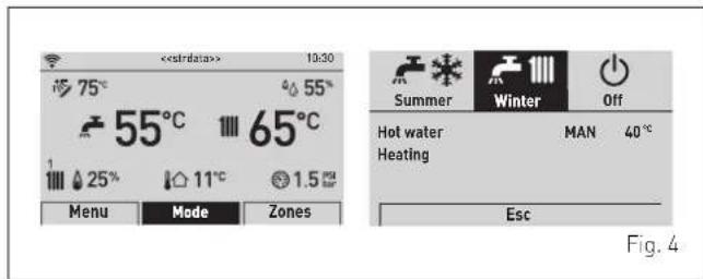
- turn the encoder to select the "Mode" (Mode) function
- press the click encoder to go to the screen to select the "
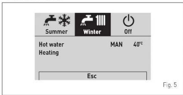
Function mode" (MODE). Turn the encoder to select the preferred mode e.g. "Winter" (Winter)
- press the click encoder to confirm "Winter" (Winter) - press the "ESC" button to go back to the "main screen".
- open one or more of the hot water valves and check that the appliance starts up
- allow the appliance to operate until hot water is produced and shut off the valves opened previously.
1.3 Settings using the MODE function
From the "Main screen":
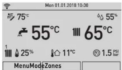
Fig. 6
- turn the encoder to select the "Mode" (Mode) function
- press the click encoder to go to the screen to select the "
Function mode" (MODE). Turn the encoder to select the preferred mode e.g. "Winter" (Winter)
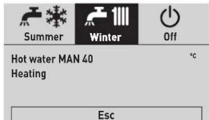
Fig. 7
- press the click encoder to confirm the highlighted "Mode" and go to the "rows"
1.3.1 Domestic hot water
- turn the encoder to select "Hot water" (DHW)
- press the click encoder to confirm "Hot water" (DHW) and open the submenu
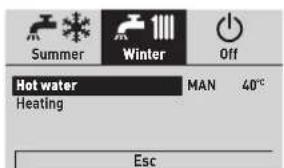
![Hot water Function Mode MAN Zone heating 45°C Program. Time [...]](/content/2026/05/855257/images/faab0b4337059f52a4e107153bf7724b67ba3f7be209633d042737f5cf2e44e7.jpg)
Fig. 8
- press the click encoder to confirm the highlighted "Row" and access the modifiable area
![Hot water Function Mode MAN Hot water setting 45°C Program. Time [...]](/content/2026/05/855257/images/79cc2abae035555ded159695fd0d6a437c4fc6dbcae422f8095a8146662ed8d9.jpg)
Fig. 9
- turn the encoder to modify the "Data/value" in the permitted field (e.g. OFF - ECO - MAN - AUTO)
- press the click encoder to confirm any modifications made and go back to the row "Function mode" [Function Mode].

The characteristics of each operating mode available are described below:
| Function mode | Description |
| OFF | DHW (domestic hot water) request NOT active |
| ECO | Instantaneous operation (factory setting) |
| MAN | DHW 3-star function ALWAYS active (with PAR 37 = 1) |
| AUTO_ON | MAN mode operation when the time slot has been activated |
| AUTO_OFF | ECO mode operation when the time slot has been deactivated |

CAUTION
For information on boiler time programming, see "Time Programming".
This function is included on boiler models with instantaneous hot water function, with PAR 47 = 1 the function activates when MAN or AUTO mode is set in the ON bands.
Moreover, this function:
- is activated if, during a domestic hot water (DHW) request, the burner turns on for more than 5 seconds
- the function keeps the burner active (at minimum power) at the end of the DHW request, depending on the temperature of the primary heat exchanger
- the function has a maximum duration of 1 hour
- the total execution time is reloaded only if the 3-star function is interrupted by a DHW request
- if the 3-star function is interrupted by a heat request from the heating circuit, or by a request with higher priority, the function will be deactivated.

CAUTION
When the "DHW 3-star" function is activated, it is recommended to set the "Hot water set" to a value below 45^ to prevent excessive temperatures when water starts being drawn.

CAUTION
Setting of the remote control SIME HOME PLUS: to disable the DHW 3-star function (enabling in ECO mode), set the domestic hot water (DHW) function to AUTO mode and disable the MON-SUN period for all time bands.
1.3.3 Heating
- Turn the encoder to select "Heating" (Heating)
- press the click encoder to confirm "Heating" (Heating) and open the submenu "Zone" (Zones)
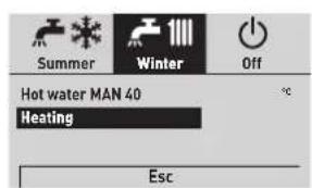
![Heating Zone 1 Zone 2 [...]](/content/2026/05/855257/images/886d8a60443dc4d379d95cca2336cf0e7f1977c7a98a55dcc014ed4924777cd3.jpg)
Fig. 10

- turn the encoder to select the desired zone e.g. Zone 1 (Zone 1) or Zone 2 (Zone 2)
- press the click encoder to confirm the highlighted zone and go to the row
![Zone 1 Information [...] Settings [...] Config [...]](/content/2026/05/855257/images/ebd55d60fd64e0bdd70548121380b9482c2e80c96d2fd1752f6de9432a7d5633.jpg)
Fig. 11
- Turn the encoder until selecting the desired function, e.g. Settings

![Zone 1 Information [...] Settings [...] Config [...]](/content/2026/05/855257/images/3ad523a88f203c1b936bb79e0a96aeb1f8c93451037b03af740fa840064d2d81.jpg)
Fig. 12
- press the click encoder to confirm the selected submenu and access the relevant data display
![Room 1 - Settings Function Mode AUTO Set AUTO comfort 20.5°C Set AUTO reduced 17.0°C Set MAN 19.2°C Program. Time [...]](/content/2026/05/855257/images/75eaec261e678051cbb4c40835b719b0090ce98a56d5798538e8bc0b9cef7cf0.jpg)
Fig. 13
- press the click encoder to confirm the highlighted "Row" and access the modifiable area
![Room 1 - Settings Function Mode AUTO Set AUTO comfort 20.5°C Set AUTO reduced 17.0°C Set MAN 19.2°C Program. Time [...]](/content/2026/05/855257/images/f06744c1e46f395ac7ddfffdcfec6c3c1f8307d91a7779918d6785580ff4c581.jpg)
Fig. 14

- turn the encoder to modify the "Data/value" in the permitted field (e.g. OFF - ECO - MAN - AUTO)
- press the click encoder to confirm any modifications made and go back to the row "Function mode" (Function Mode).

CAUTION
For information on boiler time programming, see "Time Programming".

CAUTION
The settings described above must be done for both zones.
1.4 Fault warnings
If a fault occurs, the screen "Anomaly in progress" (Fault in progress) will appear in place of the "main screen". For the main fault codes, a brief description and suggestions for the user are displayed, based on the seriousness and the frequency with which the fault reappears.
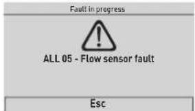
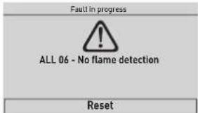
Fig. 15
The fault may be transient (volatile) or it may cause an appliance block.
To restore normal operating conditions:
- if the fault is transient, eliminate the cause of the fault
- if the fault causes a block, eliminate the cause of the fault
and then press the "RESET" (Reset) button; press the encoder to confirm.

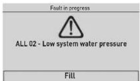
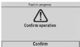
Fig. 16

CAUTION
For a full list of faults, see "Malfunction codes and possible solutions".
1.5 Time Programming
The control panel allows up to a maximum of four daily time bands to be managed for the domestic hot water function and the heating function described below.
During the programmed time band, the boiler works in COM-FORT heating mode, while outside the programmed time band it works in REDUCED heating mode:
- press the encoder click to confirm "Program.Time" (Program.Time) and go into the modifiable area
![Heating Time Program MondayDay/s [1] 06:00 - 08:00 [3] [2] 11:00 - 13:00 [4] 18:00 - 23:00 Confirm](/content/2026/05/855257/images/8af40e40faa6b9fa49c4ff4ef907762dfa923f5da5edc69ea4565b54e1f0851f.jpg)
Fig. 17
- turn the encoder to select the "Single days" or the "Group of days"
- press the click encoder to confirm the required selection and access the first "Adjustable time" [1]
![Heating Time Program MondayDay/s 0246 81 01 21 41 61 82 02 22 4 [1] 06:00 - 08:00 [3] - [2] 11:00 - 13:00 [4] 18:00 - 23:00 Confirm](/content/2026/05/855257/images/11b9c06fb41ec55380be649a47ae473737ce4c04a80cc107dc17380a39334992.jpg)
Fig. 18
- turn the encoder to modify the "Data/value" on the basis of the required time
- press the click encoder to confirm the modification and move to the next "Data/value"
![Heating Time Program MondayDay/s 0246 81 01 21 41 61 82 02 22 4 [1] 06:00 - 08:00 [3] [2] 11:00 - 13:00 [4] 18:00 - 23:00 Confirm](/content/2026/05/855257/images/89491a53a93dd9f25c12bfbaf7afa984a19eb1f8d99694feb46795d26d36b8f4.jpg)
Fig. 19
– continue in this way until all the necessary modifications have been made for each day of the week or group of days.
NOTE: The user must work in a CIRCULAR manner, meaning ALWAYS MOVING FORWARDS, even if a mistake is made.

CAUTION
If NO time band is required, set the start and stop times of that band to the same value (e.g. [3] 14:00-14:00).
- When all modifications have been made, turn the encoder to select "Confirm" (Confirm) and press the click encoder to go back to "Single days" or "Groups of days"
- press the "ESC" button to go back to the "main screen".
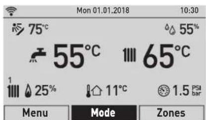
Fig. 20
2 SHUTDOWN
2.1 Temporary shutdown
If the user wishes to interrupt boiler operation temporarily:
- turn the encoder to select the "Mode" (Mode) function
- press the click encoder to go to the screen to select the
"Function mode" (MODE). Turn the encoder to select "OFF" - press the click encoder to switch the boiler off.
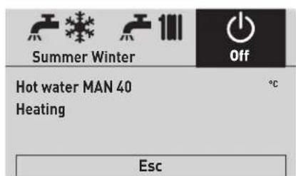
Fig. 21

ELECTRICAL HAZARD
The boiler will still be powered.
If the user is away temporarily, for a weekend, short trip etc and if the outside temperature is at ZERO:
- set the main system switch to "OFF"
- close the gas valve.
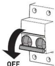
Fig. 22
2.2 Shutting down for long periods
If the boiler is to be left unused for a long period, the following operations need to be carried out:
- switch off the boiler as specified in the "Temporary shutdown" section
- set the main system switch to "OFF"
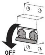
Fig. 23
- close the gas valve
- close the heating and domestic hot water isolation valves
- drain the heating and domestic hot water system if there is the risk of freezing.

CAUTION
Contact the Qualified Technical Personnel if the procedure described above cannot be easily carried out.
3 MAINTENANCE
3.1 Adjustments
For the appliance to operate correctly and efficiently it is recommended that the User calls upon the services of a Professionally Qualified Technician to carry out ANNUAL maintenance.

CAUTION
Maintenance interventions must ONLY be carried out by professionally qualified personnel who will follow the indications provided in the INSTALLATION AND MAINTENANCE MANUAL.
3.2 External cleaning

WARNING
- Should it be necessary to access the areas in the bottom part of the appliance, make sure that the system components and pipes are not hot (risk of burning).
- Before performing any maintenance, put on protective gloves.
3.2.1 Cleaning the cladding
When cleaning the cladding, use a cloth dampened with soap and water or alcohol for stubborn marks.

IT IS FORBIDDEN
to use abrasive products.
4 DISPOSAL
4.1 Disposal of the equipment (European Directive 2012/19/EU)
At the end of their life span, the appliance and electrical and electronic devices coming from households or classifiable as household waste must be delivered to appropriate waste collection systems, in accordance with the law and with Directive 2012/19/EU. This product was designed and manufactured for minimising its impact on the environment and on human health, but it contains components that could be detrimental if managed improperly. The symbol (crossed-out wheelie bin) depicted here and also appearing on your appliance means that the appliance at the end of its life must be managed in accordance with the law and treated as electrical and electronic waste. Before delivering the appliance for its disposal, consult the applicable provisions of the laws in force in the country where the appliance is used and get information on the authorised waste disposal facilities by contacting the relevant local offices.

IT IS FORBIDDEN
dispose of the product with urban waste.
DESCRIPTION OF THE APPLIANCE
TABLE OF CONTENTS
5 DESCRIPTION OF THE APPLIANCE 16
5.1 Characteristics 16
5.2 Check and safety devices 16
5.3 Identification 16
5.3.1 Technical Data Plate 17
5.4 Structure 18
5.5 Technical features....19
5.6 Main water circuit 20
5.7 Sensors....20
5.8 Expansion vessel....21
5.9 Circulation pump 21
5.10 Control panel 22
5.11 Wiring diagram 23
5 DESCRIPTION OF THE APPLIANCE
5.1 Characteristics
MURELLE.HT are last generation condensing wall mounted boilers which Sime has produced for heating and domestic hot water production. The main design choices made by Sime for the MURELLE.HT boilers are:
- the total pre-mix microflame burner combined with a steel heat exchanger for heating and a rapid heat exchanger for DHW
- the sealed combustion chamber which can be classified "Type C" or "Type B" in relation to the room where the boiler is installed, depending on the smoke outlet configuration adopted during installation
- the command and control microprocessor electronic board provides efficient management of both heating and hot water production. It can also be connected to a remote control with an Open Therm protocol or to room thermostat and/or external sensor. If connected to an external sensor, the boiler temperature varies on the basis of the external temperature according to a selected optimal climatic curve providing significant energy and economic savings.
Other special features of the MURELLE.HT boilers are:
- the anti-freeze function which activates automatically if the temperature of the water inside the boiler falls below the value set under parameter "PAR 7" and, where there is an external sensor, if the external temperature falls below the value set under parameter "PAR 8"
- the anti-blocking function of the pump and diverter valve, this activates automatically every 24 hours if no request for heat has been made
- the chimney sweep function lasts 15 minutes and makes the job of the qualified technician easier when measuring the parameters and combustion efficiency
- domestic hot water comfort function which allows the time necessary for the hot water to become available to be reduced and ensures that the temperature is stable
- screen display of the operating and self-diagnostic parameters with error code display when the fault occurs. This makes repair interventions easier and allows appliance operation to be restored correctly.
5.2 Check and safety devices
The MURELLE.HT boilers are equipped with the following check and safety devices:
- thermal safety thermostat 100°C
- 3 bar relief valve
- heating water pressure transducer
- delivery sensor
- return sensor
- DHW sensor
- smoke flue gas probe.

IT IS FORBIDDEN
To commission the appliance with safety devices which do not work or which have been tampered with.

WARNING
Safety device may only be replaced by professional qualified personnel using Sime original spare parts.
5.3 Identification
The MURELLE.HT boilers can be identified by means of:
1 Packaging label: this is located on the outside of the packaging and provides a code, the serial number of the boiler and the bar code.
2 Energy Efficiency Label: this is positioned on the outside of the packaging to notify the User of the level of energy savings and reduced environmental pollution produced by the appliance.
3 Technical Data Plate: this is located inside the front panel of the boiler and provides the technical specification, appliance performance and any other information required by law.
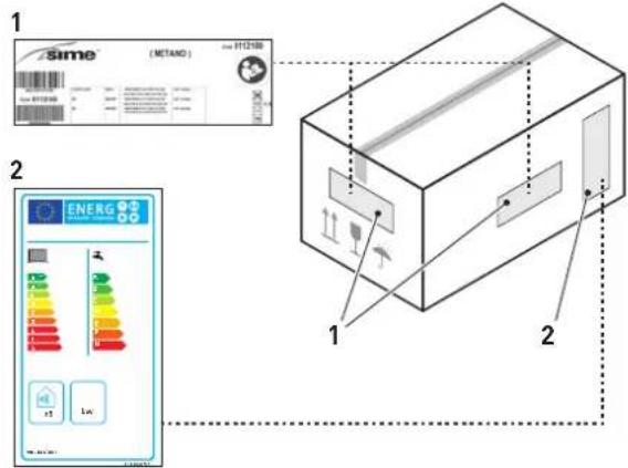
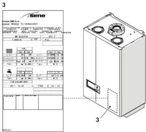
Fig. 24
5.3.1 Technical Data Plate
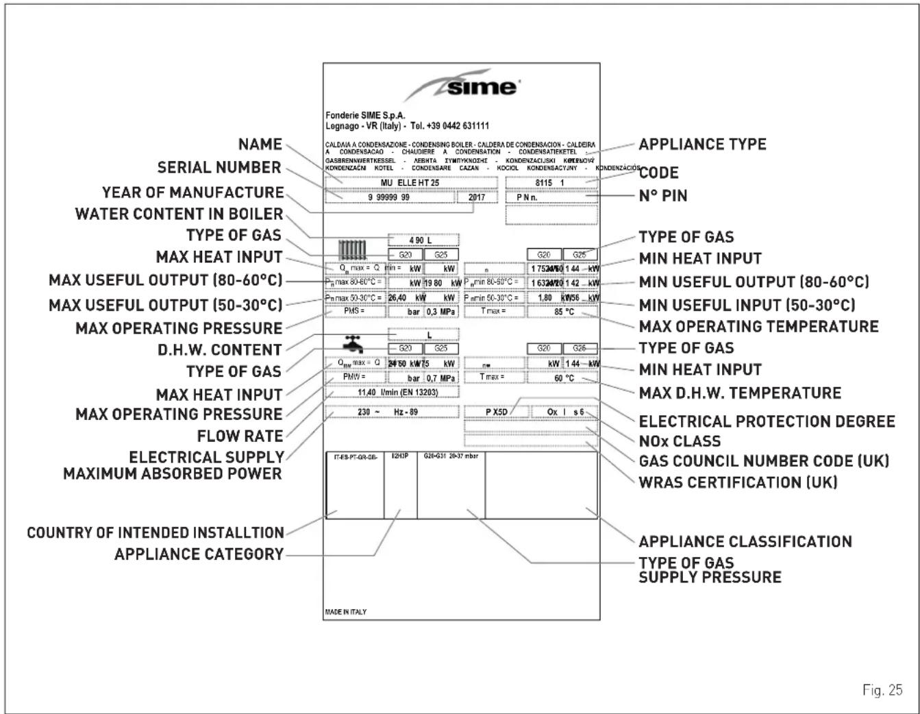

CAUTION
Tampering with, removing or failing to display the identification plate or carrying out any other operation which does not allow safe identification of the product or which may hinder installation and maintenance operations.
5.4 Structure
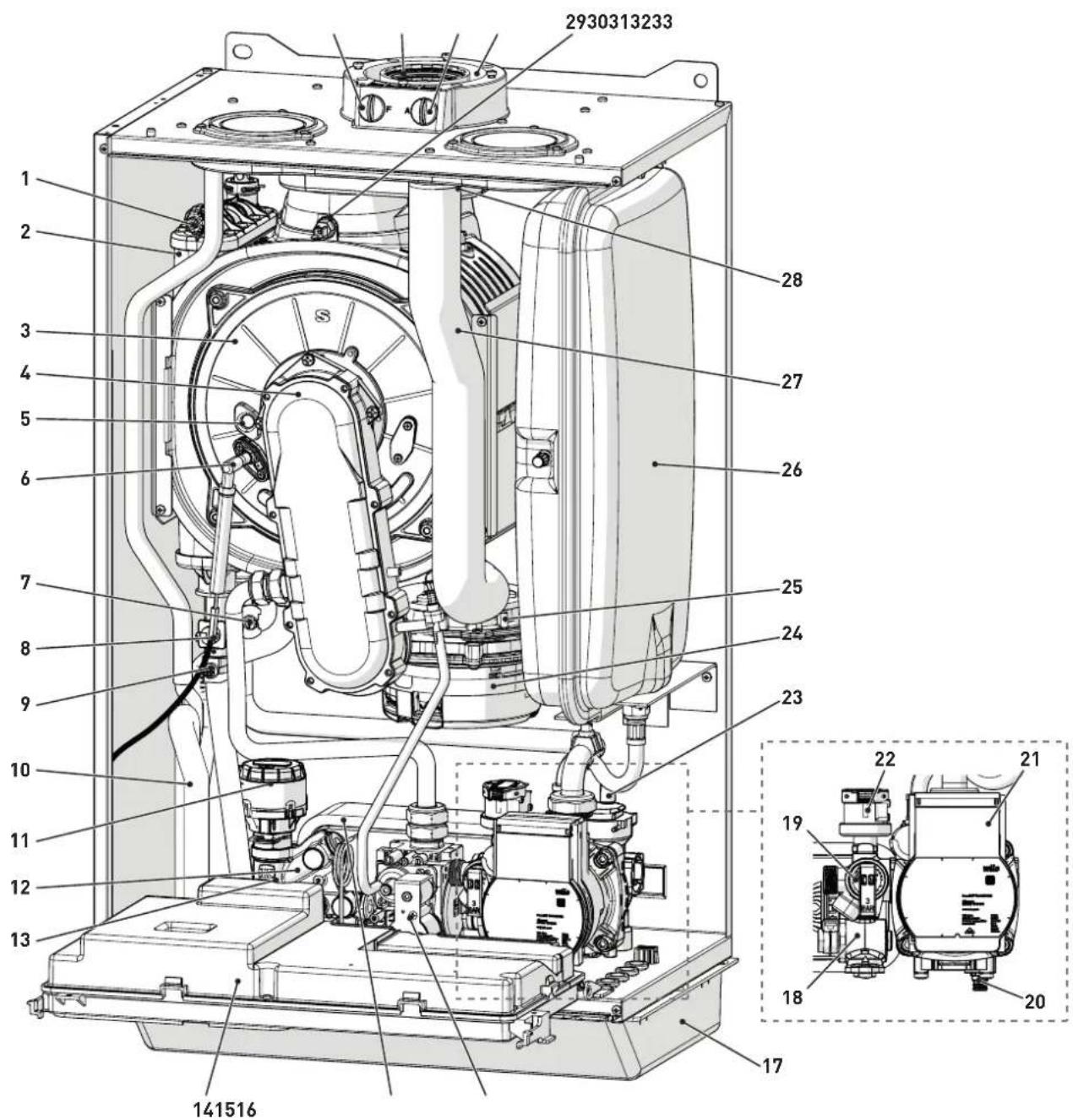
1 Heat exchanger bleed point
2 Air side heat exchanger
3 Combustion chamber door
4 Oversleeve
5 Flame viewing window
6 Ignition/detection electrode
7 Return sensor (SR)
8 Heat safety thermostat
9 Delivery sensor
10 Condensate siphon
11 Diverter valve
12 System filling unit
13 Domestic hot water sensor
14 Control panel
16 Gas valve
17 Tap fittings cover
15 Domestic hot water heat exchanger
18 Domestic hot water filter
19 System relief valve
20 Boiler drain
21 System pump
22 Water pressure transducer
23 Automatic bleed valve
24 Fan
25 Air-gas mixer
26 Expansion vessel
27 Air inlet pipe
28 Air-smoke chamber
29 Smoke flue gas probe
30 Air inlet
31 Air inlet analysis take-off point
32 Smoke outlet
33 Take-off point for smoke analysis
Fig. 26
5.5 Technical features
| DESCRIPTION | MURELLE.HT | |||
| 25 30 35 | ||||
| CERTIFICATIONS | ||||
| Country of intended installation | IT - ES - PT - EN - FR - DE - NL - CZ - RU | |||
| Fuel G20 / G31 | ||||
| PIN number 1312CS6249 | ||||
| Category II2H3P | ||||
| Appliance classification | B23P - B53P - C[10]3 - C13 - C33 - C43 - C53 - C63 - C83 - C93 | |||
| Class NOx (*) 6 (< 56 mg/kWh) | ||||
| DHW rated useful heat output | kW | 24,5 | 29,5 | 34,5 |
| HEATING PERFORMANCE | ||||
| HEAT INPUT (**) | ||||
| Nominal flow (Qn max) | kW | 24,5 | 29,5 | 34,5 |
| Minimum flow G20/G31 (Qn min) | kW | 1,75 / 3,5 | 2,1 / 4,2 | 2,5 / 6,0 |
| HEAT OUTPUT | ||||
| Nominal useful output G20/G31 (80-60°C) (Pn max) | kW | 24,2 | 29,1 | 33,9 |
| Nominal useful output G20/G31 (50-30°C) (Pn max) | kW | 26,4 | 31,8 | 37,2 |
| Minimum G20 (80-60°C) (Pn min) | kW | 1,65 | 1,93 | 2,33 |
| Minimum G20 (50-30°C) (Pn min) | kW | 1,81 | 2,17 | 2,60 |
| Minimum G31 (80-60°C) (Pn min) | kW | 3,30 | 3,86 | 5,60 |
| Minimum G31 (50-30°C) (Pn min) | kW | 3,62 | 4,34 | 6,19 |
| EFFICIENCY | ||||
| Max useful efficiency (80-60°C) | % | 98,7 | 98,8 | 98,2 |
| Min useful efficiency (80-60°C) | % | 94,3 | 91,9 | 93,3 |
| Max useful efficiency (50-30°C) | % | 107,9 | 107,8 | 107,7 |
| Min useful efficiency (50-30°C) | % | 103,4 | 103,3 | 103,2 |
| Useful efficiency at 30% of load | % | 108,6 | 108,5 | 108,6 |
| Losses after shutdown at 50°C | W | 95,0 | 101,0 | 113 |
| DOMESTIC HOT WATER PERFORMANCE | ||||
| Nominal heat input (Qnw max) | kW | 24,5 | 29,5 | 34,5 |
| Minimum heat input G20/G31 (Qnw min) | kW | 1,75 / 3,5 | 2,1 / 4,2 | 2,5 / 6,0 |
| Specific D.H.W. flow rate ΔT 30°C (EN 13203) | l/min | 11,4 | 14,0 | 16,1 |
| Continuous D.H.W. flow rate (ΔT 25°C / ΔT 35°C) | l/min | 14,1 / 10,1 | 17,0 / 12,1 | 19,7 / 14,1 |
| Minimum D.H.W. flow rate | l/min | 2 | 2 | 2 |
| Max (PMW) / Min Pressure | bar | 7 / 0,5 | 7 / 0,5 | 7 / 0,5 |
| kPa | 700 / 50 | 700 / 50 | 700 / 50 | |
| ENERGY PERFORMANCE | ||||
| HEATING | ||||
| Heating seasonal energy efficiency class | A | A | A | |
| Heating seasonal energy efficiency | % | 93 | 93 | 93 |
| Sound power | dB(A) | 51 | 52 | 53 |
| DOMESTIC HOT WATER | ||||
| Domestic hot water energy efficiency class | A | A | A | |
| Domestic hot water energy efficiency | % | 82,4 | 82,2 | 80,8 |
| Stated domestic hot water profile load | XL | XL | XL | |
| ELECTRICAL SPECIFICATIONS | ||||
| Power supply voltage | V | 230 | 230 | 230 |
| Frequency | Hz | 50 | 50 | 50 |
| Absorbed electrical power (Qn max) | W | 89 | 99 | 105 |
| Absorbed electrical power at (Qn min) | W | 61 | 63 | 64 |
| Absorbed electrical power in stand-by | W | 5 | 5 | 5 |
| Electrical protection degree | IP | X5D | X5D | X5D |
| COMBUSTION DATA | ||||
| Smoke temperature at Max/Min flow (80-60°C) | °C | 79,9 / 68,4 | 79,5 / 70,1 | 79,4 / 62,3 |
| Smoke temperature at Max/Min flow (50-30°C) | °C | 56,4 / 52,8 | 54,8 / 53,0 | 58,1 / 51,8 |
| Smoke flow Max/Min | g/s | 11,5 / 0,9 | 14,3 / 1,0 | 15,9 / 1,2 |
| CO2 at Max/Min flow rate (G20) | % | 9,3 / 8,8 | 9,0 / 9,0 | 9,5 / 9,0 |
| CO2 at Max/Min flow rate (G31) | % | 10,0 / 10,0 | 10,0 / 9,7 | 10,3 / 10,3 |
| NOx measured | mg/kWh | 38 | 45 | 45 |
(*) NOx class according to UNI EN 15502-1:2021
(**) Heat input calculated using the lower heat output (Hi)
| DESCRIPTION | MURELLE.HT | |||
| 25 30 35 | ||||
| NOZZLES - GAS | ||||
| Number of nozzles No. 2 2 2 | ||||
| Nozzle diameter (G20-G31) | mm | 3,3 / 2,6 - 2,6 / 1,9 | 3,4 / 3,2 - 2,9 / 2,2 | 4,0 / 3,5 - 3,0 / 2,8 |
| Gas consumption at Max/Min flow rate (G20) m | ^3/h | 2,59 / 0,185 3,12 / 0,22 3,65 | / 0,26 | |
| Gas consumption at Max/Min flow rate (G31) | kg/h | 1,90 / 0,27 | 2,29 / 0,33 | 2,68 / 0,47 |
| Gas supply pressure (G20/G31) | mbar | 20 / 37 20 / 37 20 / 37 | ||
| kPa | 2 / 3,7 | 2 / 3,7 | 2 / 3,7 | |
| TEMPERATURE - PRESSURE | ||||
| Max operating temperature (T max) | °C | 85 | ||
| Heating adjustment range | °C | 20÷80 | ||
| Domestic hot water adjustment range | °C | 10÷60 | ||
| Max operating pressure (PMS) | bar | 3 | ||
| kPa | 300 | |||
| Water content in boiler | l | 4,9 | 5,5 | 6,0 |
Lower Heat Output (Hi)
G20 Hi. 9.45 kW/m³ (15°C, 1013 mbar) - G31 Hi. 12.87 kW/kg (15°C, 1013 mbar)
5.6 Main water circuit
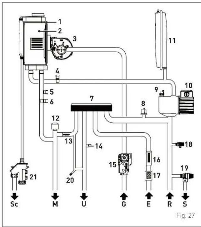
KEY:
M System delivery
R System return
U Domestic hot water outlet
E Domestic hot water inlet
S Safety valve outlet
G Gas supply
Sc Condensate outlet
1 Condensing heat exchanger
2 Combustion chamber
3 Fan
4 Return sensor (SR)
5 Thermal safety thermostat
6 Delivery sensor
7 Domestic hot water heat exchanger
8 Pressure transducer
9 Automatic bleed valve
10 Pump
11 System expansion vessel
12 Diverter valve
13 Automatic by-pass
14 Domestic hot water sensor
15 Gas valve
16 Domestic hot water flow meter
17 Domestic hot water filter
18 Boiler drain
19 System relief valve
20 System filling
21 Condensate siphon outlet
5.7 Sensors
The sensors installed have the following characteristics:
- Dual sensor (thermal safety/output) NTC R25°C; 10kΩ B25°-85°C: 3435
- domestic hot water sensor NTC R25°C; 10kΩ B25°-85°C: 3435
- External temperature sensor NTC R25°C; 10kΩ B25°-85°C: 3435
| TR | 0°C | 1°C | 2°C | 3°C | 4°C | 5°C | 6°C | 7°C | 8°C | 9°C |
| 0°C | 27279 | 26135 | 25044 | 24004 | 23014 | 22069 | 21168 | 20309 | 19489 | 18706 |
| 10°C | 17959 | 17245 | 16563 | 15912 | 15289 | 14694 | 14126 | 13582 | 13062 | 12565 |
| 20°C | 12090 | 11634 | 11199 | 10781 | 10382 | 9999 | 9633 | 9281 | 8945 | 8622 |
| 30°C | 8313 | 8016 | 7731 | 7458 | 7196 | 6944 | 6702 | 6470 | 6247 | 6033 |
| 40°C | 5828 | 5630 | 5440 | 5258 | 5082 | 4913 | 4751 | 4595 | 4444 | 4300 |
| 50°C | 4161 | 4026 | 3897 | 3773 | 3653 | 3538 | 3426 | 3319 | 3216 | 3116 |
| 60°C | 3021 | 2928 | 2839 | 2753 | 2669 | 2589 | 2512 | 2437 | 2365 | 2296 |
| 70°C | 2229 | 2164 | 2101 | 2040 | 1982 | 1925 | 1870 | 1817 | 1766 | 1717 |
| 80°C | 1669 | 1622 | 1577 | 1534 | 1491 | 1451 | 1411 | 1373 | 1336 | 1300 |
| 90°C | 1266 | 1232 | 1199 | 1168 | 1137 | 1108 | 1079 | 1051 | 1024 | 998 |
| 100°C | 973 |
Correspondence of Temperature Detected/Resistance
Examples of reading:
TR = 75^ R = 1925
TR = 80^ R = 1669.
5.8 Expansion vessel
The expansion vessel installed on the boilers has the following characteristics:
| Description U/M | MURELLE.HT | ||
| 25 30 35 | |||
| Total capacity l 10,0 | |||
| Prefilling pressure | kPa 100 | ||
| bar 1,0 | |||
| Useful capacity l 5,0 | |||
| Maximum system content (*) l 124 | |||
(\*) Conditions of:
Average operating temperature 70°C (with high temperature system 80/60°C)
Start temperature at system filling 10^ C.

CAUTION
- For systems with water content exceeding the maximum system content (as indicated in the table) an additional expansion vessel must be prearranged.
- The difference in height between the relief valve and the highest point of the system cannot exceed 6 metres. If the difference is greater than 6 metres, increase the prefilling pressure of the expansion vessel and the system when cold by 0.1 bar for each meter increase.
5.9 Circulation pump
The flow-head performance curve available for the heating system is shown in the graph below.
RESIDUAL HEAD (mbar)
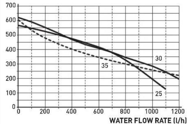
line
| WATER FLOW RATE (L/h) | Line 1 | Line 2 | Line 3 | | --------------------- | ------ | ------ | ------ | | 0 | 600 | 600 | 600 | | 200 | 500 | 500 | 500 | | 400 | 400 | 400 | 400 | | 600 | 300 | 300 | 300 | | 800 | 200 | 200 | 200 | | 1000 | 100 | 100 | 100 | | 1200 | 50 | 50 | 50 |Fig. 28

CAUTION
The appliance is equipped with a by-pass which ensures water circulation in the boiler when the thermostatic valves or cocks are used in the system.
5.10 Control panel
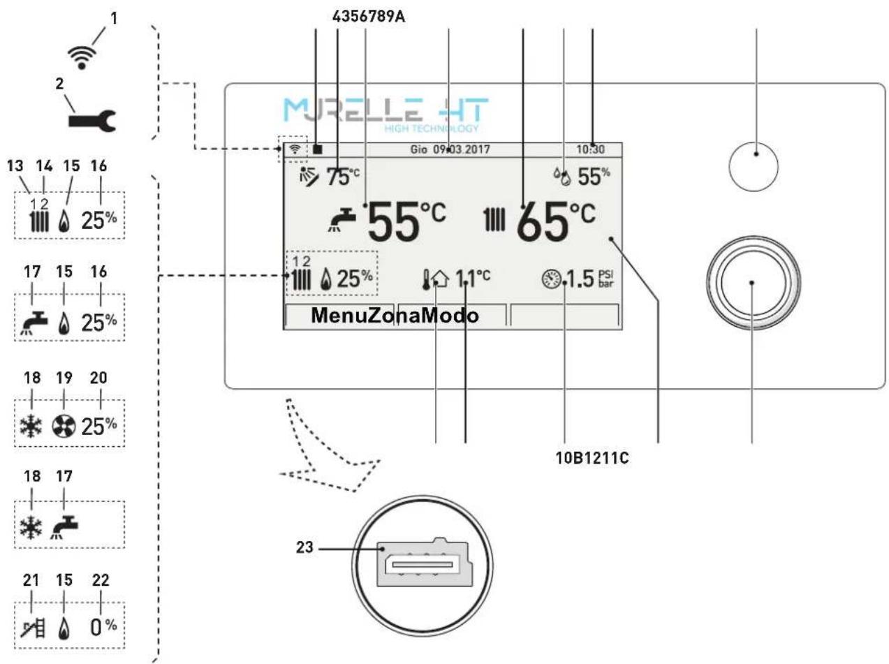
Fig. 29
A "ESC" button: go back to the previous screen LOCKOUT NOTIFICATION: when the boiler is locked, the button lights up red
B MULTI-FUNCTION ENCODER: turn to navigate the menu, press to confirm the selection
C DISPLAY
1 WiFi
2 Alarm symbol
3 Remote control, where relevant
4 Solar manifold temperature
5 DHW temperature
6 Date
7 Boiler delivery temperature
8 Room humidity level
9 Time
10 System pressure
11 Measured outdoor temperature
12 Presence of external sensor (SE)
13 Heating circuit "1" heat request active
14 Heating circuit "2" heat request active
15 Burner active
16 Burner modulation percentage
17 Domestic hot water circuit heat request active
18 Heat pump request in cold mode active
19 Heat pump active
20 Heat pump modulation percentage
21 Chimney sweep function active
22 Chimney sweep function modulation percentage
23 Programming connector

CAUTION
Remove the protective film on the display after the appliance is used for the first time.
5.11 Wiring diagram
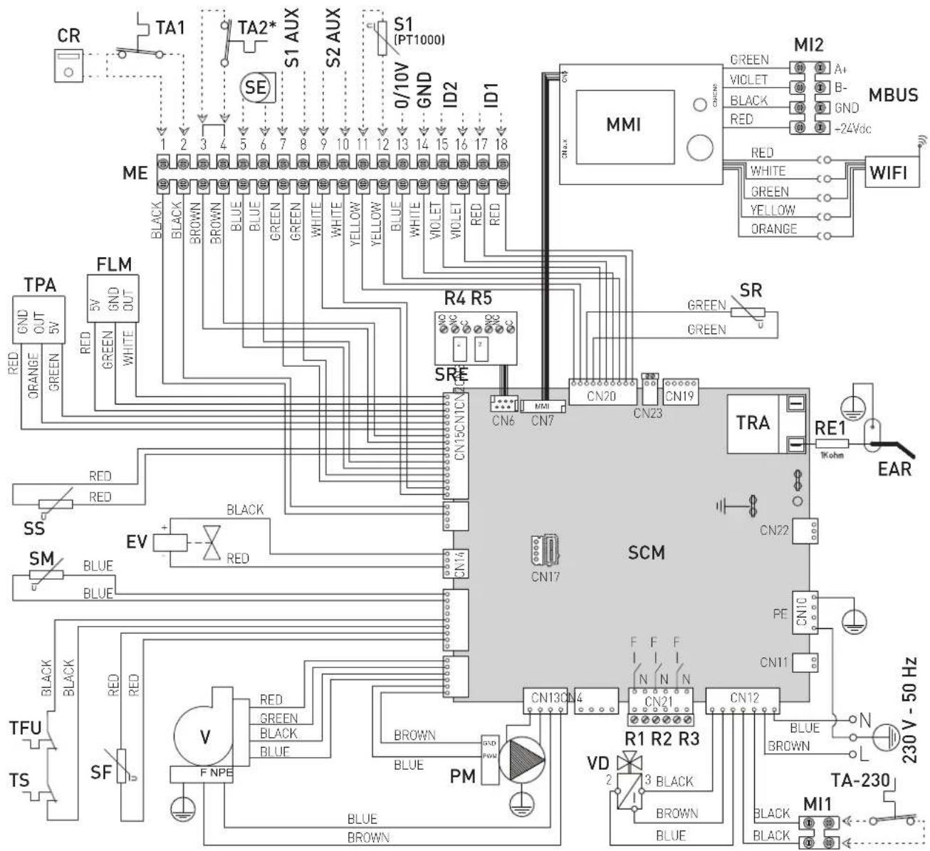
| L | Line / Live | SR | Return sensor (SR) | S1-2 AUX | Configurable auxiliary sensors |
| N | Neutral | TS | Safety thermostat | S1(PT1000) | Solar manifold probe |
| F | Live | TFU | Thermal fuse | 0/10V | 0/10 V input |
| TRA | Ignition transformer | SF | Smoke flue gas probe | ID1-ID2 | Configurable digital input |
| RE1 | Resistance | FLM | Flow meter | ME | Terminals external to panel |
| PM | System modulating pump | VD | Diverter valve | MI1-MI2 | Terminals inside panel |
| V | Fan | TPA | Pressure transducer | MBUS | Connections for MOD-BUS |
| EAR | Ignition / Detection electrode | SRE | Relay board | input | |
| MMI | Control interface | WiFi | WiFi antenna board | ||
| EV | Gas solenoid valve | SCM | Control board | R1÷R2÷R3 | 230 V max 100 W output relay |
| SE | External temperature sensor | CR | Remote control (instead of air thermostat) | R4÷R5 | Dry-contact relay max 230 VAC - 100 W |
| SS | Domestic hot water sensor | TA1-TA2 | Air thermostat | ||
| TA-230 | Room thermostat 230V |
When connecting the ambient thermostat to TA1, remove the jumper on TA2 (*) if not used.
Fig. 30
CAUTION
Users must:
- To mount an omnipolar residual-current circuit breaker conforming to EN standards that allows for completely disconnecting the system in overvoltage category III conditions (that is, with a gap of at least 3 mm between the open contacts).
- Respect the connections L (Live) - N (Neutral).
- Ensure that the special power cable is only replaced with a cable ordered as a spare part and connected by professionally qualified personnel.

CAUTION
Users must:
- Connect the earth wire to an effective earthing system. The manufacturer is not responsible for any damage caused by failure to earth the appliance or failure to observe the information provided in the wiring diagrams.

IT IS FORBIDDEN
To use water pipes for earthing the appliance.
INSTALLATION AND SERVICING INSTRUCTIONS
TABLE OF CONTENTS
6 INSTALLATION 26
6.1 Receiving the product 26
6.2 Dimensions and weight.....26
6.3 Handling 26
6.4 Installation room 27
6.5 New installation or installation of a replacement appliance 27
6.6 Cleaning the system 27
6.7 Water system treatment 28
6.8 Boiler installation 28
6.9 Plumbing connections....28 6.9.1 Plumbing accessories (optional)....28
6.10 Condensate outlet/collection 29
6.11 Gas supply 29
6.12 Smoke outlet and combustion air inlet 30
6.12.1 Coaxial duct (∅ 60/100mm and ∅ 80/125mm) ...31
6.12.2 Separate ducts (∅ 60mm and ∅ 80mm) ... 31
6.12.3 Separate ducts (Ø 80mm) with duct kit C(10)3...33
6.13 Electrical connections....34
6.13.1 External temperature sensor.... 35
6.13.2 Chrono-thermostat or Air Thermostat .... 36
6.13.3 Installing the WiFi antenna 36
6.14 System solutions 37
6.14.1 Quick boiler system type configuration.... 37
6.14.2 Plant solution diagrams with zone room thermostat.... 38
6.14.3 Plant solution diagrams with wireless room probes and radio-frequency receiver ..... 45
6.15 Displaying the set system solution .....49
6.16 Refilling or emptying....49
6.16.1 REFILL operations 49
6.16.2 EMPTYING operations 50
7 COMMISSIONING 51
7.1 Preliminary operations 51
7.2 Before commissioning 51
7.3 Main control panel display and settings ..... 51
7.3.1 Settings using the MODE function.....51
7.3.1.1 Domestic hot water 51
7.3.8 Navigating from the ZONE function.....64
7.4 Parameter setting and display 65
7.5 List of parameters....66
7.6 Fault / malfunction codes....69
7.7 Checks and adjustments 70
7.7.1 Chimney sweeper function.... 70
7.8 Gas conversion....71
7.8.1 Preliminary operations.... 71
8 MAINTENANCE 73
8.1 Adjustments....73
8.2 External cleaning....73
8.2.1 Cleaning the cladding....73
8.3 Cleaning the inside of the appliance 73
8.3.1 Removing components.... 73
8.3.2 Cleaning the burner and the combustion chamber 74
8.3.3 Checking the ignition/detection electrode... 74
8.3.4 Final operations 74
8.4 Checks 74
8.4.1 Checking the smoke duct.... 74
8.4.2 Checking the expansion vessel pressure .. 74
8.5 Unscheduled maintenance 75
8.6 Malfunction codes and possible solutions ..... 75
9 ANNEXES 77
9.1 Boiler product board 77
9.2 Boiler technical sheet 78
sime 6 INSTALLATION

CAUTION
The appliance must only be installed by the Sime Technical Service or by qualified professionals who MUST wear suitable protective safety equipment.
6.1 Receiving the product
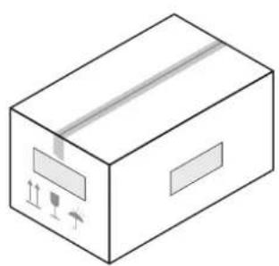
MURELLE.HT appliances are delivered in a single unit protected by cardboard packaging.
natural_image
Isometric illustration of a cardboard box with visible shipping labels and directional arrows (no text or symbols)Fig. 31
The plastic bag found inside the packaging contains the following:
- Installation, use and maintenance manual
– Paper template for boiler installation - Certificate of warranty
- Hydrostatic test certificate
- System booklet
- WiFi antenna
- External sensor
- Energy label
- Flue gas diaphragm
- Condensate outlet corrugated pipe
- Bag with expansion plugs

IT IS FORBIDDEN
To leave packaging material around or near children since it could be dangerous. Dispose of it as prescribed by legislation in force.
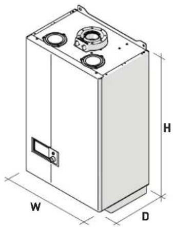
6.2 Dimensions and weight
natural_image
Isometric line drawing of a rectangular industrial or electrical enclosure with labeled dimensions (W, D, H) and circular components on top (no text or symbols beyond labels)Fig. 32
| Description | MURELLE.HT | ||
| 25 30 35 | |||
| W (mm) 450 450 450 | |||
| D (mm) 315 315 315 | |||
| H (mm) 760 760 760 | |||
| Weight (kg) 32,4 34,0 35,6 | |||
6.3 Handling
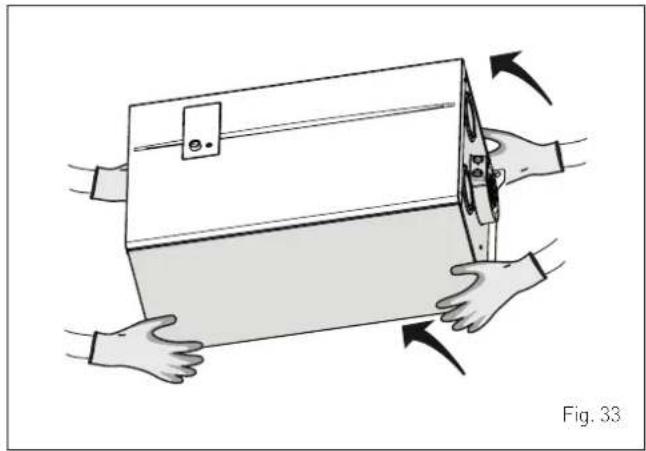
Once the packaging has been removed, the appliance is to be handled manually, tilting it slightly, lifting it and applying pressure in the points indicated in the figure.
natural_image
Illustration of hands holding a box with arrows indicating motion or force, labeled 'Fig. 33' (no text or symbols on the diagram itself)
IT IS FORBIDDEN
To grip the appliance casing. Hold the "solid" parts of the appliance such as the base and structural frame.

WARNING
Use suitable tools and accident protection when removing the packaging and when handling the appliance. Observe the maximum weight that can be lifted per person.
6.4 Installation room
The room where the appliance is to be installed must comply with the Technical Regulations and Legislation in force. It must be equipped with suitably sized ventilation openings when the installation is a "TYPE B" installation.
The minimum temperature of the installation room must NOT be lower than -5 °C.

CAUTION
- Make sure that the appliance is positioned in an area out of direct sunlight, the weather and protected against damp and wet.
- Before assembling the appliance, the installer MUST make sure that the wall supports the weight.
– Remember to consider the space needed in order to access the safety/adjustment devices and to carry out maintenance interventions (see Fig. 34).
APPROXIMATE MINIMUM DISTANCES
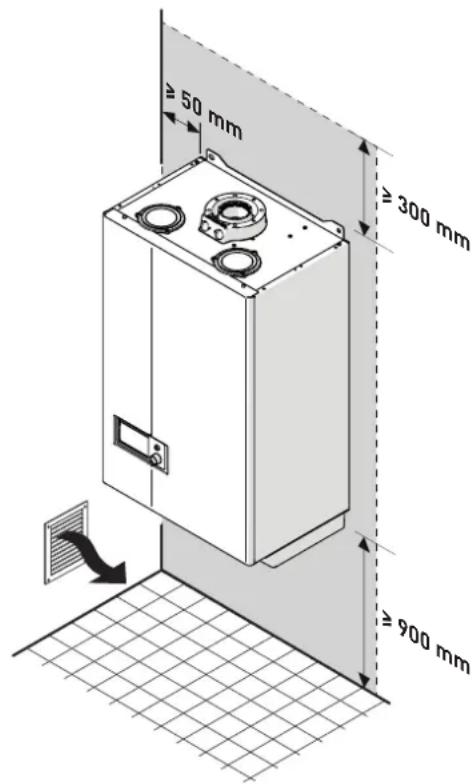
Fig. 34
6.5 New installation or installation of a replacement appliance
When MURELLE.HT boilers are installed on old systems or systems requiring updating, it is recommended the installer checks that:
- the connecting flue pipe is suitable for the combustion temperature of the appliance, calculated and manufactured in compliance with Standards, that it is as straight as possible, air tight, isolated, with no obstructions or restriction and that it has appropriate condensate collection and evacuation systems
– the electrical system has been manufactured in compliance with specific Standards and by professionally qualified personnel - the fuel delivery line and the tank (LPG) comply fully with specific Standards
- the expansion vessel ensures total absorption of the fluid dilation in the system
- the pump flow-head performance is sufficient for the system characteristics
- the system is clean, free of any sludge, deposits, de aerated and air tight. For system cleaning, please refer to the relevant paragraph.

CAUTION
The manufacturer declines all liability for any damage caused by an incorrect implementation of the smoke outlet or for an excessive use of additives.
6.6 Cleaning the system
Before installing the appliance on a newly constructed system or replacing a heat generator on an existing system, it is important that the system is thoroughly cleaned to remove sludge, slag, dirt, residue etc.
Before removing an old heat generator from an existing system, it is recommended that the user:
- puts a descaling additive into the water system
- allows the system to work with the generator active for a few days
- drains the dirty water from the system and flushes the system with clean water once or more than once.
If the old generator has already been removed or is not available, replace it with a pump to circulate water in the system and then proceed as described above.
Once cleaning operations have been carried out and before installing the new appliance, it is recommended that a fluid is added to the water system to protect it from corrosion and deposits.

CAUTION
- For further information on the type of additive and usage, please contact the appliance manufacturer.
- Please remember that you MUST install a Y filter (not supplied with the appliance) on the heating system return (R).
6.7 Water system treatment
When filling and restoring the system it is good practice to use water with:
- aspect: clear if possible
- Ph: 6÷8
- hardness: < 25°f.
If the water characteristics are different from those indicated, it is recommended that a safety filter is used on the water delivery pipe to retain impurities, and a chemical treatment system to protect against possible deposits and corrosion which could affect boiler operation.
If the systems are only low temperature systems, it is recommended that a product is used to prevent the development of bacteria.
In any case, please refer to and comply with the legislation and specific technical standards in force in the country where the appliance will be used.
6.8 Boiler installation
MURELLE.HT boilers leave the factory with a paper template for installation onto a solid wall.
For installation:
- position the paper template (1) on the wall (2) where the boiler is to be mounted
- make the holes and insert the expansion plugs (3)
- hook the boiler onto the plugs.
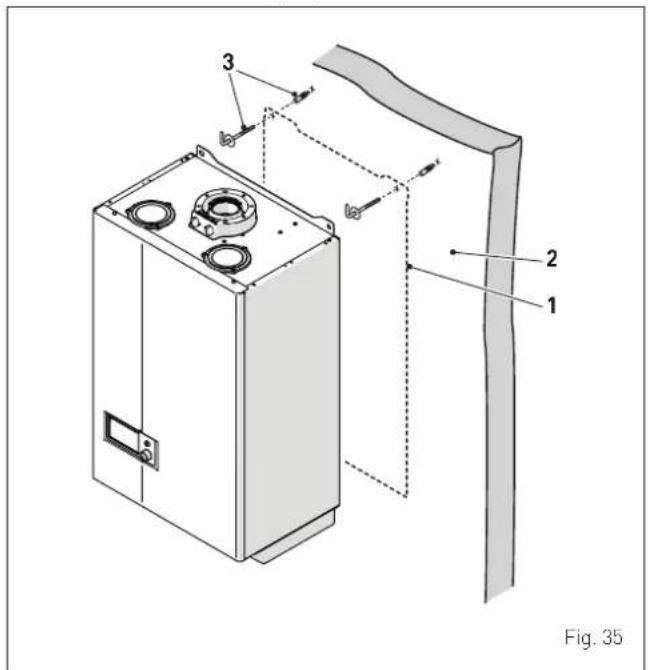

CAUTION
The height of the boiler is to be such that disassembly and maintenance interventions are facilitated.
6.9 Plumbing connections
The plumbing connections have the following characteristics and dimensions.
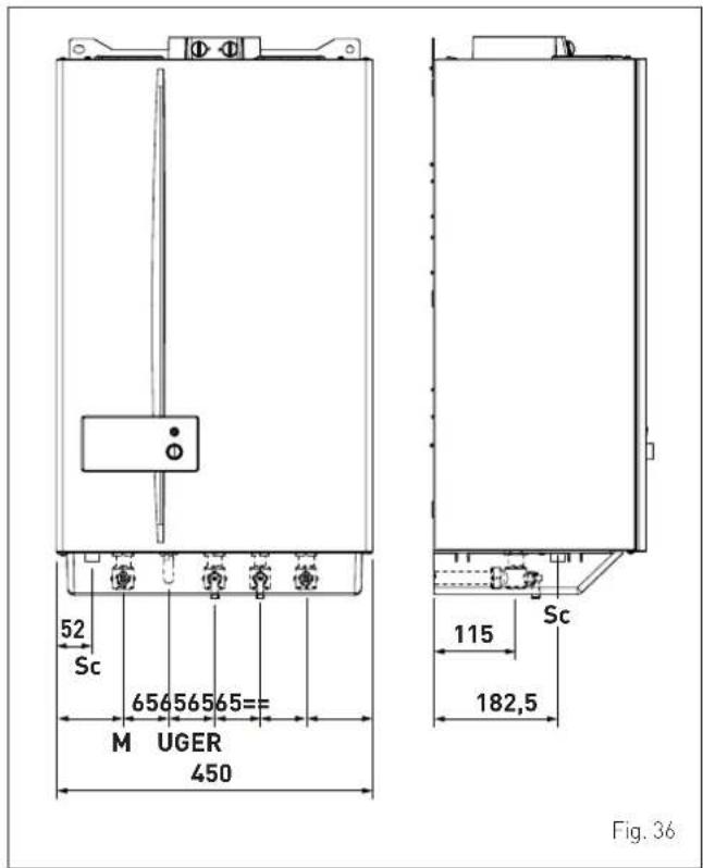
| Description | MURELLE.HT | ||
| 25 30 35 | |||
| M - System delivery ∅ 3/4" G | |||
| R - System return ∅ 3/4" G | |||
| U - Domestic hot water output ∅ 1/2" G | |||
| E - Domestic hot water inlet ∅ 1/2" G | |||
| G - Gas supply ∅ 3/4" G | |||
| Sc - Condensate outlet | ∅ 20 mm | ||
6.9.1 Plumbing accessories (optional)
To facilitate plumbing and gas connections to the systems, the accessories as shown in the table below are available and are to be ordered separately from the boiler.
| DESCRIPTION | CODE |
| Assembly template | 8081221 |
| Lower template element (50 pieces) | 8075437 |
| Curve kit | 8075418 |
| Curve and valve kit with connections from DIN to SIME | 8075443 |
| Cocks kit | 8091806 |
| Valve kit with connections from DIN to SIME | 8075442 |
| Wall mount replacement kit for other makers | 8093900 |
| Polyphosphate dosing kit | 8101700 |
| Dosing recharge kit | 8101710 |
| Solar kit for instant combination boilers | 8105101 |
| Condensate pump kit | 8105302 |
| Compact dirt separator | 8101750 |
| Anti-freeze heaters kit (-15°C) | 8089816 |
| Concentrator + one wireless room probe kit | 8094121 |
| Contact sensor downstream of the compensator | 6277122 |
| Band sensor + mix valve | 8082269 |
| Wireless room sensor | 8094110 |
NOTE: kit instructions are supplied with the accessory itself or are to be found on the packaging.
6.10 Condensate outlet/collection
In order to collect the condensate, it is recommended that:
- the appliance condensate outlets and the smoke outlet are ducted
- a neutralising device is prearranged
- the outlet incline is >3%.

CAUTION
- The condensate outlet duct must be airtight, suitably sized to that of the siphon and must not be restricted at any point.
- The condensate outlet must be constructed in full compliance of the National or Local regulations in force.
- Before commissioning the appliance, fill the siphon with water.
6.11 Gas supply
MURELLE.HT boilers leave the factory specifically prearranged for G20 gas or G31. The G20 models can be converted to function with G31 using the "specific nozzle kit" (optional) provided by Sime on request separately from the boiler.
If changing the type of gas to be used, carry out the entire "GAS CONVERSION" phase of the appliance.
The boiler must be connected to the gas mains in full compliance with the installation standards in force in the country where the appliance will be used.
Before connecting the boiler to the gas mains, the user must ensure that:
- the type of gas is correct for the appliance
- the pipes are clean
- the gas supply pipe is the same dimension as or greater than that of the boiler fitting (G3/4") and with a load loss less than or equal to that contemplated between the gas mains and the boiler.

WARNING
Once installation has been completed, check that the joints are air tight as indicated in the installation Standards.

CAUTION
It is recommended that the gas line has a suitable filter.

CAUTION
If the gas supply is changed from G20 to G31, mark the box on the TECHNICAL DATA PLATE.
G31 - 37 mbar

6.12 Smoke outlet and combustion air inlet
MURELLE.HT boilers must be equipped with appropriate smoke flue ducts and combustion air inlet ducts. These ducts are considered an integral part of the boiler and are provided bySime as an accessory kit, to be ordered separately from the appliance on the basis of the type permitted and the system requirements.
Permitted types of exhausts and ducts
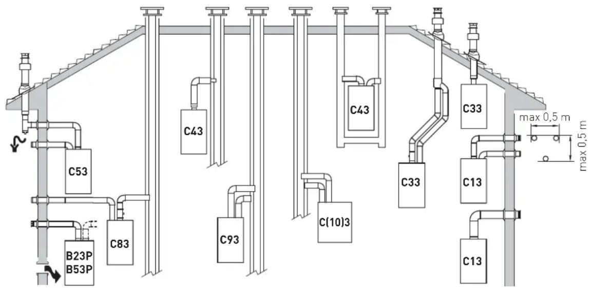
| Outlet Description | Coaxial duct Separate ducts | |||||
| ∅ 60/100 ∅ 80/125 ∅ 80 ∅ 60 ∅ 50 | ||||||
| B23P | Combustion air inlet into the atmosphere and smoke outlet to open airNOTE: opening for combustion air (6 cm2x kW) | X X X | ||||
| B53P | Combustion air inlet into the atmosphere and smoke outlet to open airNOTE: opening for combustion air (6 cm2x kW) | X X X | ||||
| C(10)3 | Type C appliance connected, via conduits, to a collective pipe designed for more than one appliance. The collective pipe is made up of two conduits connected to a terminal which also feeds in air from outside the burner and evacuates the combustion products externally through concentric orifices or those close enough to result in the same wind conditionsNOTE: the boiler can be type C(10)3 only with accessory code 6296543/629550If this accessory is used, it is necessary to increase by 15% the value of the Minimum power heating/domestic hot water (premix); set the value of PAR 20 = 15 Install this accessory only when separate flues are installed on the boiler; DO NOT use it when concentric flue are installed | X | ||||
| C13 | Concentric wall smoke outlet The pipes can start from the boiler but the outlets must be concentric or close together (no more than 50 cm) to be subject to similar wind conditions | X X X X X | ||||
| C33 | Concentric roof smoke outlet The pipes can start from the boiler but the outlets must be concentric or close together (no more than 50 cm) to be subject to similar wind conditions | X X X | ||||
| C43 | Outlet and inlet in shared or separate flue pipes but subjected to similar wind conditions | X X X X X | ||||
| C53 | Separate wall or roof inlet and outlet in different pressure areasNOTE: the inlet and outlet must never be positioned on opposing walls | X | ||||
| C83 Outlet in single or shared flue or with inlet on wall X X X | ||||||
| C93 Separate outlet and inlet in shared flue pipe X X X | ||||||
| C63 Outlet and inlet made from pipes which are sold and certified separately | ||||||
P: smoke outlet system designed to operate with positive pressure.
All the measurements are in mm.

WARNINGS
- The smoke flue and the connection to the flue pipe must be in compliance with the national and local standards and legislation in force in the country where the appliance will be used.
- The use of rigid ducts which are resistant to temperature, condensate, mechanical stress and are air-tight is compulsory.
- Outlet ducts which are not isolated are a risk of danger.
6.12.1 Coaxial duct ( 60/100mm and 80/125mm)
Coaxial accessories
| Description | Code | |
| 60/100 mm | 80/125 mm | |
| Coaxial duct kit 8096250 8096253 | ||
| Extension W. 1000 mm 8096150 8096171 | ||
| Extension W. 500 mm 8096151 8096170 | ||
| Vertical extension W. 140 mm with smoke analysis take-off point | 8086950 - | |
| Adapter for 80/125 mm - 8093150 | ||
| Additional 90° curve 8095850 8095870 | ||
| Additional 45° curve 8095950 8095970 | ||
| Tile with joint 8091300 8091300 | ||
| Roof outlet terminal W. 1284 mm 8091205 8091205 | ||
Load loss - Equivalent lengths
| Model | Leq (linear metres) | |
| 60/100 mm | 80/125 mm | |
| 90° curve 1,5 2 | ||
| 45° curve 1 1 | ||
Minimum-Maximum Lengths
| Model | Duct Length ∅ 60/100 | Duct Length ∅ 80/125 | ||||||
| W Horizontal (m) | H Vertical (m) | W Horizontal (m) | H Vertical (m) | |||||
| Min. | Max. | Min. | Max. | Min. | Max. | Min. | Max. | |
| MURELLE. HT 25 | - | 4,5 | 1,3 | 6 | - | 8 | 1,2 | 10 |
| MURELLE. HT 30 | - | 5 | 1,3 | 7 | - | 10 | 1,2 | 13 |
| MURELLE. HT 35 | - | 4 | 1,3 | 6 | - | 8 | 1,2 | 11 |
Smoke outlet and combustion air inlet fittings
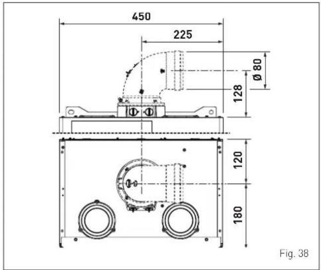
6.12.2 Separate ducts ( 60mm and 80mm)
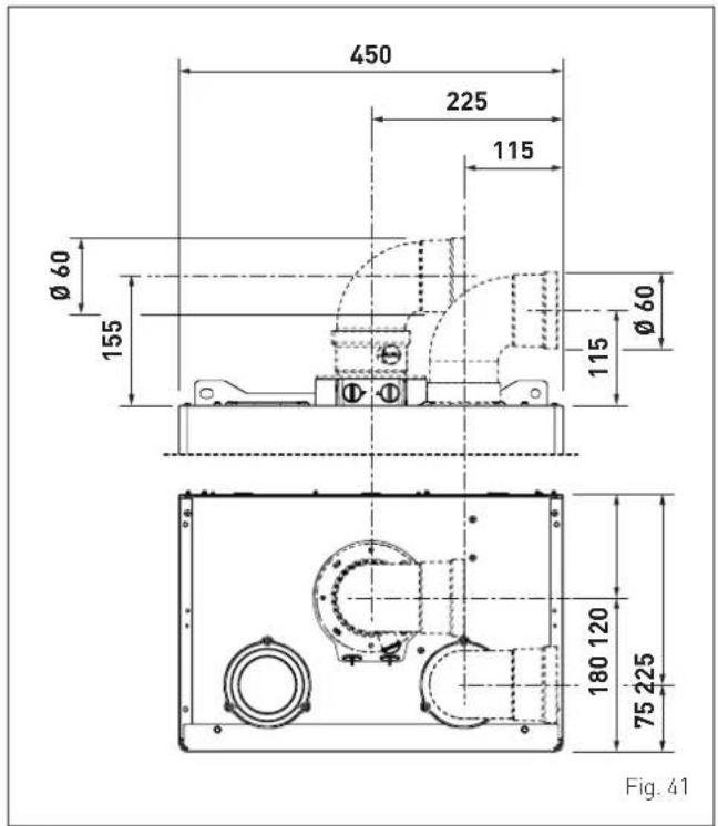
The smoke outlet and combustion air inlet can be built with separate ducts, instead of concentric ducts, using the "SEPARATE DUCTS KIT", product code 8089912 for ∅ 80 mm or product code 8089913 for ∅ 60 mm. The accessories must be ordered separately from the boiler, and connected to the other accessories, chosen from those listed in the table below.
Accessory 8089912 for ∅ 80 mm is supplied with an INLET DIAPHRAGM NOT TO BE USED.
Accessory 8089913 for ∅ 60 mm is supplied with an inlet collar which must be replaced with the one on the boiler.
Separate accessories
| Description | Code | |
| Diameter ∅ 60 (mm) | Diameter ∅ 80 (mm) | |
| 90° curve M-F (6 pieces) | - | 8077450 |
| 90° curve M-F | 8089921 | - |
| 90° curve M-F (with take-off point) | 8089924 | - |
| Extension W. 1000 mm (6 pieces) | - | 8077351 |
| Extension W. 1000 mm | 8089920 | - |
| Extension W. 500 mm (6 pieces) | - | 8077350 |
| Wall outlet terminal | 8089541 | 8089501 |
| Internal and external ring nut kit | 8091510 | 8091500 |
| Inlet terminal | 8089540 | 8089500 |
| 45° curve M-F (6 pieces) | - | 8077451 |
| 45° curve M-F | 8089922 | - |
| Manifold | 8091400 | 8091400 |
| Tile with joint | 8091300 | 8091300 |
| Roof outlet terminal W. 1381 mm | 8091204 | 8091204 |
| Reducer M-F ∅ 60 | 8089923 | - |
| Inlet/outlet fitting | 8091401 | 8091401 |
| Coaxial outlet ∅ 80/125 L. 885 mm | 8091210 | 8091210 |
| Duct kit C(10)3MURELLE.HT 25 | - | 6296550 (GPL) |
| - | 6296543 (Methane) | |
| Duct kit C(10)3MURELLE.HT 30 | - | 6296543 |
| Duct kit C(10)3MURELLE.HT 35 | - | |
Smoke outlet
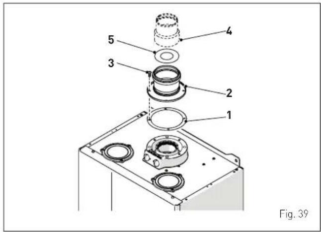
The smoke outlet can be constructed by attaching the kit components to the boiler fitting: the ∅125 seal (1), the collar (2) and the screws (3) to fix everything in place. The reducer (4) only comes in kit 8089913.

CAUTION
MURELLE.HT boilers are provided as standard with a steel diaphragm (5), code 6028607 for the 25 and 30 models, code 6028605 for the 35 models, which should be positioned on the flue gas outlet flange when the total load loss for the separate ducts is below 9 mmH2O. Where the total load loss exceeds 9 mmH2O, do not use the diaphragm. The total load loss is determined by the sum of the load losses of the single accessories that make up the pipework. It should not exceed 15 mmH2O.
Combustion air inlet
The combustion air inlet, with separate ducts, is assembled as follows:
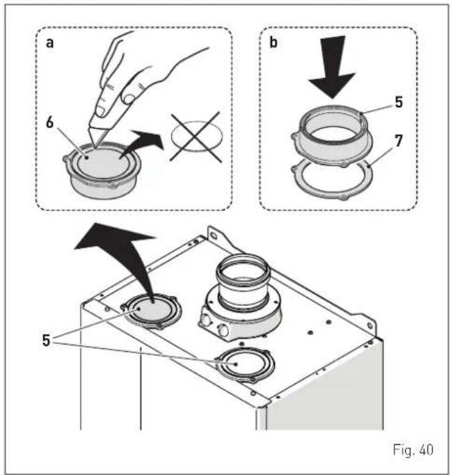
- remove the air outlet cap (5); choose your preferred air vent from the two available
- cut the bottom of the cap (6) using a suitable tool (see (a))
- turn over the cap (5) (see (b)) and refit it on the air vent, inserting the seal (7)
- fix everything in place with the screws removed previously.
The overturned cap (5) is now the attachment for the first component on the air inlet duct.
NOTE: If installing kit 8089913, the cap (5) on the boiler must be replaced with the cap supplied in the accessory kit.
Smoke outlet and combustion air inlet fittings
Load loss accessory ∅ 60 mm
| Description Code | Load loss (mm H_2O ) | ||||
| MURELLE.HT 25 MURELLE.HT 30 | |||||
| Inlet Outlet Inlet Outlet | |||||
| Separate duct kit | 8089913 | 2,50 | 0,50 | 2,50 | 0,50 |
| 90° curve MF | 8089921 | 0,40 | 0,90 | 0,50 | 1,10 |
| 45° curve MF | 8089922 | 0,35 | 0,70 | 0,45 | 0,90 |
| Horizontal extension W. 1000 mm | 8089920 | 0,40 | 0,90 | 0,50 | 1,10 |
| Vertical extension W. 1000 mm | 8089920 | 0,40 | 0,60 | 0,50 | 0,70 |
| Wall terminal | 8089541 | 0,50 | 1,20 | 0,80 | 1,40 |
| Wall coaxial outlet (*) | 8091210 | - - - - | |||
| Roof outlet terminal [*] | 8091204 | 0,80 | 0,10 | 1,10 | 0,15 |
| Description Code | Load loss (mm H2O) | ||
| MURELLE.HT 35 | |||
| Inlet Outlet | |||
| Separate duct kit | 8089913 | 2,50 0,50 | |
| 90° curve MF | 8089921 | 0,60 1,40 | |
| 45° curve MF | 8089922 | 0,55 1,20 | |
| Horizontal extension W. 1000 mm | 8089920 | 0,60 1,40 | |
| Vertical extension W. 1000 mm | 8089920 | 0,60 0,80 | |
| Wall terminal | 8089541 | -1,60 | |
| Wall coaxial outlet (*) | 8091210 | - | - |
| Roof outlet terminal (*) | 8091204 | 1,50 0,20 | |
Load loss accessory ∅ 80 mm
| Description Code | Load loss (mm H2O) | ||||
| MURELLE.HT 25 M | MURELLE.HT 30 | ||||
| Inlet Outlet | Inlet Outlet | Outlet | |||
| Separate duct kit | 8089912 | - - - - | |||
| 90° curve MF | 8077450 | 0,20 0,25 | 0,25 0,30 | ||
| 45° curve MF | 8077451 | 0,15 0,15 | 0,20 0,20 | ||
| Horizontal extension W. 1000 mm | 8077351 | 0,15 0,15 | 0,20 0,20 | ||
| Vertical extension W. 1000 mm | 8077351 | 0,15 0,15 | 0,20 0,20 | ||
| Wall terminal | 8089501 | 0,10 0,25 | 0,10 0,35 | ||
| Wall coaxial outlet (*) | 8091210 | - - - - | |||
| Roof outlet terminal (*) | 8091204 | 0,80 0,10 | 1,10 0,15 | ||
| Duct kit C(10)3 | 6296550 | - 1,2 | - 1,8 | ||
| 6296543 | - 1,2 | - 1,8 | |||
| Description Code | Load loss (mm H2O) | ||
| MURELLE.HT 35 | |||
| Inlet Outlet | |||
| Separate duct kit | 8089912 | - | - |
| 90° curve MF | 8077450 | 0,30 0,40 | |
| 45° curve MF | 8077451 | 0,25 0,25 | |
| Horizontal extension W. 1000 mm | 8077351 | 0,25 0,25 | |
| Vertical extension W. 1000 mm | 8077351 | 0,25 0,25 | |
| Wall terminal | 8089501 | 0,15 0,50 | |
| Wall coaxial outlet (*) | 8091210 | - | - |
| Roof outlet terminal (*) | 8091204 | 1,5 | 0,2 |
| Duct kit C(10)3 | 6296550 | - | 2,2 |
| 6296543 | - | 2,2 | |
(*) The losses of the roof outlet terminal at inlet include the manifold code 8091400.

CAUTION
The total maximum length is obtained by adding the length of the inlet and outlet pipes. The total load loss is determined by the sum of the load losses of the single accessories that make up the pipework. It should not exceed 15 mmH _2 O. The total extension for each single duct must not in any case exceed 25 m, even if the total load loss is less than the maximum which can be applied.
NOTE: for the boiler to operate correctly it is necessary that a minimum distance of 0.50 m of the duct is respected with a 90° inlet curve.
Example: calculation of the load loss of a MURELLE.HT 25 boiler.
| Accessories∅ 80 mm | Code | Quantity | Load loss (mm H2O) | ||
| Inlet Out | Outlet Total | ||||
| ExtensionW. 1000 mm(horizontal) | 8077351 | 9.9 x 0, | 15 - 1,35 | ||
| ExtensionW. 1000 mm(horizontal) | 8077351 | 9 - 9 x | 0,15 1,35 | ||
| 90° curve | 8077450 | 2.2 x 0, | 20 - 0,40 | ||
| 90° curve | 8077450 | 2 - 2 x | 0,25 0,50 | ||
| Wall terminal | 8089501 | 1 0,10 | - 0,10 | ||
| Wall terminal | 8089501 | 1 - 0,25 | 0,25 | ||
| TOTAL | 3.95 | ||||
Installation is permitted as the total load losses (3,95 mmH2O) of the required accessories is less than 15,0 mmH2O and the total extension for each single duct is still less than 25 m.
6.12.3 Separate ducts ( 80mm) with duct kit C(10)3
The MURELLE.HT boiler is configured for use with type C(10)3 discharge ducts. To ensure correct boiler operation, certain parameters should be modified in relation to the power and type of fuel used to power the device.
NOTE: To modify the parameters proceed as specified in the paragraph "Parameter setting and display". Contact the Sime Technical Assistance Centre for any clarifications.
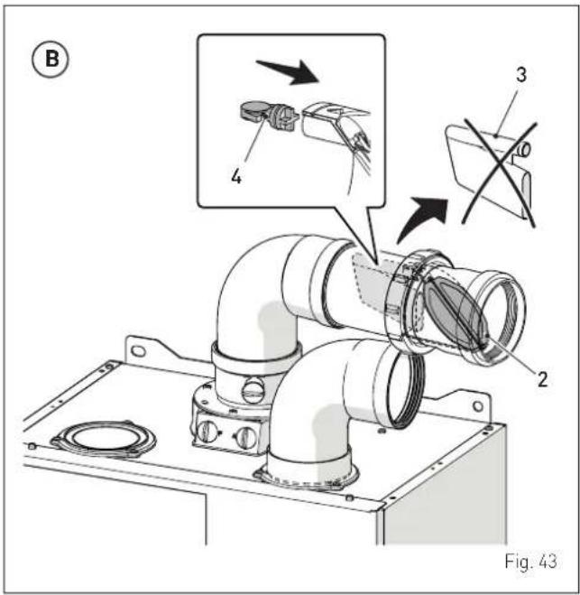
The duct kit C(10)3 (1) can be installed both vertically (A) and horizontally (B).
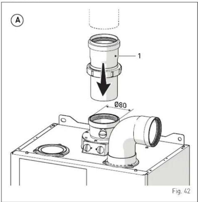
If it is installed horizontally, when positioning the internal butterfly valve make sure that its fins (2) face upwards, so that they remain closed by effect of their weight. Moreover, it is necessary to remove the siphon (3) and mount the cap (4) supplied with the kit.
6.13 Electrical connections
The power cable must be connected to a 230V (±10%) \~ 50 Hz network, observing L-N polarity and the earth connection. The network must have an omnipolar switch with category III over-voltage, in compliance with the installation rules.
If this cable needs to be replaced, an original spare must be requested from Sime.
Therefore only the connections of the original components as shown in the table are needed. These are to be ordered separately from the boiler.
| DESCRIPTION CODE | |
| Remote control HOME PLUS (open therm) 8092281 | |
| Cascade management board 8092268 | |
| Expansion card 8092272 | |
| Weekly hot-cold timer-controlled thermostat 8113509 | |

CAUTION
The maintenance interventions described must ONLY be carried out the professionally qualified personnel.

WARNING
Before carrying out any interventions described:
- set the main system switch to "OFF"
- close the gas valve
- make sure that no hot parts inside the appliance are touched.
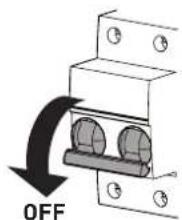
Fig. 44
To facilitate introduction of the connection wires of the optional components into the boiler:
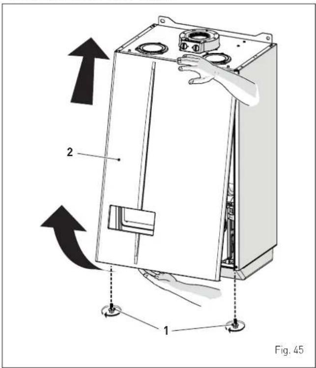
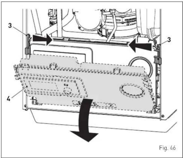
- remove the screws (1), pull the front panel (2) forwards and release it from the top by lifting it
- use the tabs (3) to release the control panel (4)
- bring the panel forwards and downwards until it is horizontal
- unscrew the screws (5) and remove the panel cover (6) carefully
- insert the connecting wires in the cable gland (7) and connect the component wires to the terminal board (8) following the indications provided on the terminal board.
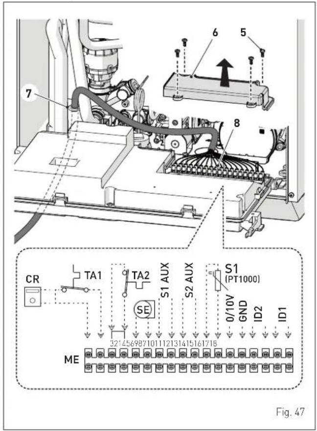
- bring the control panel (4) back to its original position and ensure that the tabs correcting lock it in place.

CAUTION
It is compulsory:
- to use an omnipolar cut-off switch, disconnect switch, in compliance with EN standards (contact opening of at least 3 mm)
- if the power cable is to be replaced, that ONLY a special cable is used with a factory produced re-wired connector, ordered as a spare part and connected by a professionally qualified person
- to connect the earth wire to an effective earthing system (*)
- that before any intervention on the boiler, the mains power is disconnected by setting the main system switch to "OFF".
(*) The manufacturer is not responsible for any damage caused by failure to earth the appliance or failure to observe the information provided in the wiring diagrams.

IT IS FORBIDDEN
To use water pipes for earthing the appliance.
6.13.1 External temperature sensor
The boiler is prearranged for connection to an external air temperature sensor and can operate with a sliding temperature.
This means that the delivery temperature sent to the boiler can vary on the basis of the external temperature depending on the climatic curve selected from those shown in the diagram (Fig. 48).
When fitting the sensor on the outside of the building, follow the instructions provided on the packaging of the product itself.
depending on the configuration used, perform the adjustment procedure of the corresponding values.
- Wireless room probes with this configuration the adjustment of the values is located in the menu:
ZONES → ZONE no._ → ADJUSTMENT
- SIME HOME PLUS; with this configuration the adjustment of the values is located in the menu:
TECHNICAL → ZONE HEATING.
Climatic curve
Delivery temperature
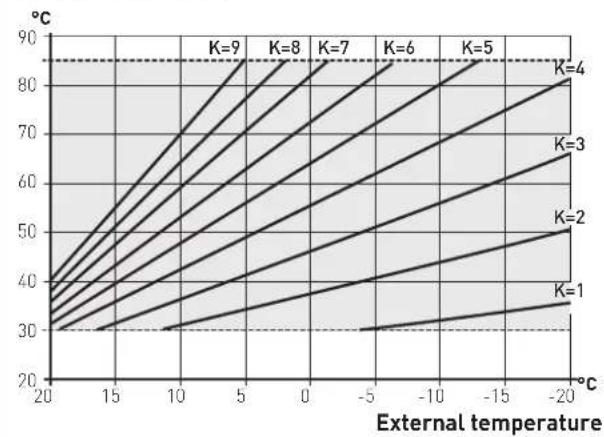
line
| External temperature | K=1 | K=2 | K=3 | K=4 | K=5 | K=6 | K=7 | K=8 | K=9 | | --------------------- | ---- | ---- | ---- | ---- | ---- | ---- | ---- | ---- | ---- | | 20 | 30 | 30 | 30 | 30 | 30 | 30 | 30 | 30 | 30 | | 15 | 35 | 35 | 35 | 35 | 35 | 35 | 35 | 35 | 35 | | 10 | 40 | 40 | 40 | 40 | 40 | 40 | 40 | 40 | 40 | | 5 | 45 | 45 | 45 | 45 | 45 | 45 | 45 | 45 | 45 | | 0 | 50 | 50 | 50 | 50 | 50 | 50 | 50 | 50 | 50 | | -5 | 55 | 55 | 55 | 55 | 55 | 55 | 55 | 55 | 55 | | -10 | 60 | 60 | 60 | 60 | 60 | 60 | 60 | 60 | 60 | | -15 | 65 | 65 | 65 | 65 | 65 | 65 | 65 | 65 | 65 | | -20 | 70 | 70 | 70 | 70 | 70 | 70 | 70 | 70 | 70 |Fig. 48
Procedure for selecting the climatic curve
To select the preferred climatic curve:
- from the "main screen" turn the encoder to select the "Mode" (Mode) function
- press the click encoder to go to the screen to select the
"Function mode" (MODE). Turn the encoder to select "Winter" (Winter) mode
- press the click encoder to confirm the highlighted "Mode" and go to the "rows"
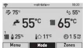
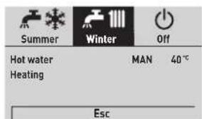
Fig. 49
- turn the encoder to select "Heating" (Heating)
- press the click encoder to confirm "Heating" (Heating) and open the submenu
![Summer Winter Off Hot water MAN 40 Heating Esc Heating Zone 1 Zone 2 [...] Fig. 50](/content/2026/05/855257/images/db125e3d35314c4dd95bc4bbbfd131da14772f3dbbb1be9c7ae03b0182ffaf0c.jpg)
- turn the encoder to select the desired zone e.g. Zone 1 (Zone 1)
- press the click encoder to confirm the highlighted item and enter the row
- turn the encoder to select "Ext. probe modul." (Ext. probe modul.)
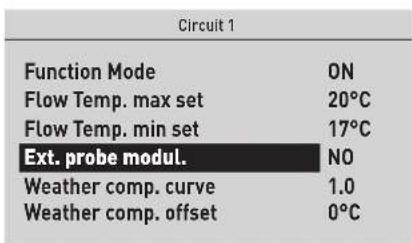
Fig. 51
- press the click encoder to confirm the highlighted "Row" and access the modifiable area
- turn the encoder to set the value to "YES" (YES)
- press the click encoder to confirm any modifications made and go back to the "Ext. probe modul." (Ext. probe modul.) row.
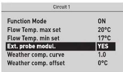
Fig. 52
Proceed in the same way to set the desired "Climatic curve" (Weather comp. curve) and "Climatic curve offset" (Weather comp. Offset).
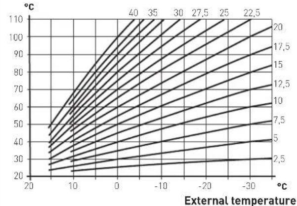
Using the boiler room thermostat; with this configuration the weather comp. curve is determined by parameters PAR12, PAR13, PAR14, PAR15, PAR16, PAR17.
Delivery temperature
line
| External temperature | Value | | --------------------- | ------ | | 20 | 2.5 | | 10 | 5 | | 0 | 7.5 | | -10 | 10 | | -20 | 12.5 | | -30 | 15 | | -40 | 17.5 | | -50 | 20 | | -60 | 22.5 | | -70 | 25 | | -80 | 27.5 | | -90 | 30 | | -100 | 32.5 | | -110 | 35 | | -120 | 37.5 | | -130 | 40 | | -140 | 42.5 | | -150 | 45 | | -160 | 47.5 | | -170 | 50 | | -180 | 52.5 | | -190 | 55 | | -200 | 57.5 | | -210 | 60 | | -220 | 62.5 | | -230 | 65 | | -240 | 67.5 | | -250 | 70 | | -260 | 72.5 | | -270 | 75 | | -280 | 77.5 | | -290 | 80 | | -300 | 82.5 | | -310 | 85 | | -320 | 87.5 | | -330 | 90 | | -340 | 92.5 | | -350 | 95 | | -360 | 97.5 | | -370 | 100 | | -380 | 102.5 | | -390 | 105 | | -400 | 107.5 |Fig. 53
6.13.2 Chrono-thermostat or Air Thermostat
The electrical connection of the chrono-thermostat or air thermostat has already been described. When fitting the component in the room where the readings are to be taken, follow the instructions provided on the packaging of the product itself.
6.13.3 Installing the WiFi antenna
To install the WiFi antenna provided with the boiler, follow the procedure described below:
- remove the WiFi antenna (1) from the document pouch
- remove the protective cap on the connector (2) in the lower part of the boiler
- connect the WiFi antenna (1) to the connector (2)
- position the WiFi antenna in one of the three slots (3) on the cover (4). Choose the slot that guarantees the best signal reception in the room, ensure the WiFi antenna is positioned with the flashing LED light facing away from the boiler.

CAUTION
To configure the app and WiFi network, please see the relevant documentation provided with the boiler.
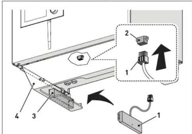
Fig. 54

IT IS FORBIDDEN
- Modify/tamper with the WiFi antenna connection cable.
- Position the WiFi antenna inside the boiler.
6.14 System solutions
6.14.1 Quick boiler system type configuration
Parameter "TSP 02 = Hydraulic configuration" is used to quickly configure the type of system installed after the boiler. According to the value set for this parameter, one of the following system solutions is selected:
- Solution 1 = System with instant boiler with two direct multi-zone circuits
- Solution 2 = System with instant boiler with a mixed multi-zone circuit
- Solution 3 = System with instant boiler with a direct multi-zone circuit and a mixed multi-zone circuit
- Solution 5= System with instant boiler with a mixed multi-zone circuit and a remote hot water tank for preheating domestic hot water
- Solution 6 = System with instant boiler with two direct multi-zone circuits and a remote hot water tank for preheating domestic hot water
- Solution 8 = System with instant boiler with one direct multi-zone circuit and a remote solar hot water tank for preheating domestic hot water
- Solution 9 = System with instant boiler with a mixed multi-zone circuit and a remote solar hot water tank for preheating domestic hot water
- Solution 10 = System with instant boiler with one direct multi-zone circuit, a mixed multi-zone circuit and a remote solar hot water tank for preheating domestic hot water
- Solution 12 = System with instant boiler with one direct multi-zone circuit and a hot/cold mode system
- Solution 14 = System with instant boiler with one mixed multi-zone circuit, a fan coil and a hot/cold mode system
- Solution 15 = System with instant boiler with one direct multi-zone circuit, a remote solar hot water tank for preheating domestic hot water, and a hot/cold mode system
To set parameter "TSP 02", follow the procedure described in the section "Parameter setting and display".

CAUTION
In relation to the value set under parameter "TSP 02", the following parameters take on the values shown in the table.
| CHOOSEN HYDRUALIC SETUP 1 2 3 4 5 6 8 9 | 10 12 14 | 15 | |||||||||||
| TSP | Description Range Parameter values | ||||||||||||
| 04 | System connected to circuit 1 | 0 = high temperature1 = low temperature | 0 1 | 1 1 1 | 0 0 1 | 1 0 1 | 0 | ||||||
| 26 | Configuring the DHW 0 = rapid 0 0 0 0 0 | 0 0 0 0 0 0 0 | |||||||||||
| 30 | Relay 1 function | 2 = direct zone 1 | 2 | 2 | 2 | 2 | 2 | 2 | 2 | 2 | 2 | 12 | 12 |
| 31 | Relay 2 function | 1 = solar pump7 = direct zone 28 = mix valve (position A) | 7 8 | 8 8 8 | 7 1 8 | 8 8 8 | 1 | ||||||
| 32 | Relay 3 function | 0 = not used1 = solar pump8 = mix valve (position A)9 = mix valve (position B) | 0 9 | 9 9 9 | 0 0 9 | 9 9 9 | 17 | ||||||
| 33 | Relay 4 function | 0 = not used1 = solar pump7 = direct zone 29 = mix valve (position B) | 0 | 0 | 7 | 0 | 0 | 0 | 0 | 1 | 1 | 11 | 11 |
| 34 | Relay 5 function | 0 = not used7 = direct zone 2 | 0 0 | 0 0 0 | 0 0 0 | 7 7 2 | 0 | ||||||
| 36 | Configuring SC input (PT1000) | 0 = not used1 = solar sensor2 = system safety thermostat | 0 2 | 2 2 2 | 0 1 1 | 1 0 2 | 1 | ||||||
| 37 | Configuring input SAUX 2 | 0 = not used3 = solar hot water tank sensor4 = mix zone sensor | 0 4 | 4 4 4 | 0 3 4 | 4 1 4 | 3 | ||||||
| 38 | Configuring input SAUX 2 | 0 = not used2 = preheated DHW inlet sensor3 = solar hot water tank sensor | 0 0 | 0 2 2 | 2 2 3 | 3 0 1 | 1 | ||||||
| 39 | Configuring digital input 1 | 0 = not used7 = system safety thermostat TSI (for low temperatures) | 0 0 | 0 0 0 | 0 0 7 | 7 6 6 | 6 | ||||||
| 40 | Configuring digital input 2 | 0 = not used | 0 | 0 | 0 | 0 | 0 | 0 | 0 | 0 | 0 | 7 | 7 |
| 45 | Enabling preheating | 0 = Disabled1 = Enabled | 0 0 | 0 1 1 | 1 1 0 | 0 0 0 | 0 | ||||||
| 46 | Enabling solar function | 0 = Disabled1 = Enabled | 0 0 | 0 0 0 | 0 1 1 | 1 0 0 | 0 | ||||||

CAUTION
The boilers can be equipped with zone room thermostats (TZ) or wireless room probes (SA) and radio-frequency receiver (RF). Verify which of these components is fitted on the boiler and consult the relative diagrams shown below.
6.14.2 Plant solution diagrams with zone room thermostat
Solution 1: System with two direct multi-zone circuits
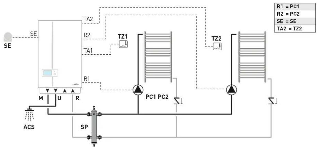
flowchart
graph TD
    A["SE"] --> B["PEL"]
    B --> C["M"]
    B --> D["U"]
    B --> E["R"]
    B --> F["SP"]
    F --> G["ACS"]
    B --> H["TZ1"]
    H --> I["PC1"]
    H --> J["PC2"]
    H --> K["TZ2"]
    K --> L["PC1"]
    K --> M["PC2"]
    K --> N["TZ2"]
    style A fill:#f9f,stroke:#333
    style B fill:#ccf,stroke:#333
    style C fill:#cfc,stroke:#333
    style D fill:#fcc,stroke:#333
    style E fill:#cff,stroke:#333
    style F fill:#ffc,stroke:#333
    style G fill:#fcf,stroke:#333
    style H fill:#cff,stroke:#333
    style I fill:#ffc,stroke:#333
    style J fill:#cff,stroke:#333
    style K fill:#ffc,stroke:#333
    style L fill:#cfc,stroke:#333
    style M fill:#fcc,stroke:#333
M System delivery
U Domestic hot water output
R Boiler return
DHW Domestic hot water
SE External temperature sensor
PC1 Direct circuit pump 1
PC2 Direct circuit pump 2
TZ1-2 Zone ambient thermostat
SP Hydraulic separator
Solution 2: System a mixed multi-zone circuit
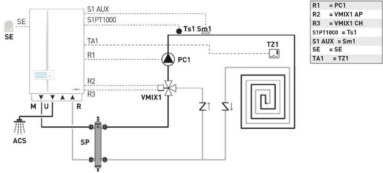
flowchart
graph TD
    A["SE"] --> B["S1 AUX"]
    B --> C["S1PT1000"]
    C --> D["TA1"]
    D --> E["PC1"]
    E --> F["TZ1"]
    F --> G["VMIX1"]
    G --> H["Z↑"]
    H --> I["Σ↓"]
    I --> J["SP"]
    J --> K["M U R ACS"]
    style A fill:#f9f,stroke:#333
    style B fill:#ccf,stroke:#333
    style C fill:#cfc,stroke:#333
    style D fill:#fcc,stroke:#333
    style E fill:#cff,stroke:#333
    style F fill:#ffc,stroke:#333
    style G fill:#cfc,stroke:#333
    style H fill:#fcc,stroke:#333
    style I fill:#cfc,stroke:#333
    style J fill:#fcc,stroke:#333
    style K fill:#fff,stroke:#333
M System delivery
U Domestic hot water output
R Boiler return
DHW Domestic hot water
SE External temperature sensor
PC1 Circuit pump 1
VMIX1 Mixer valve circuit 1
Sm1 Circuit 1 delivery sensor
Ts1 Circuit 1 safety thermostat
TZ1 Zone ambient thermostat
SP Hydraulic separator
Solution 3: System with a direct multi-zone circuit and a mixed multi-zone circuit
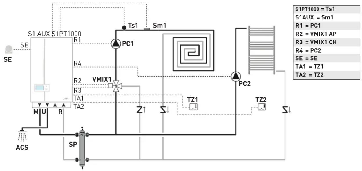
flowchart
graph TD
    A["SE"] --> B["S1 AUX S1 PT1000"]
    B --> C["PC1"]
    C --> D["VMIX1"]
    D --> E["TA1"]
    D --> F["TA2"]
    B --> G["AS"]
    G --> H["M U R"]
    H --> I["SP"]
    I --> J["Z ↑"]
    I --> K["S ↓"]
    I --> L["TZ1"]
    I --> M["TZ2"]
    C --> N["Ps1"]
    N --> O["Sm1"]
    O --> P["PC2"]
    P --> Q["TZ2"]
    Q --> R["S ↓"]
    style A fill:#f9f,stroke:#333
    style B fill:#ccf,stroke:#333
    style C fill:#cfc,stroke:#333
    style D fill:#fcc,stroke:#333
    style E fill:#cff,stroke:#333
    style F fill:#ffc,stroke:#333
    style G fill:#cfc,stroke:#333
    style H fill:#fcc,stroke:#333
    style I fill:#ffc,stroke:#333
    style J fill:#cfc,stroke:#333
    style K fill:#fcc,stroke:#333
    style L fill:#ffc,stroke:#333
    style M fill:#cfc,stroke:#333
    style N fill:#cfc,stroke:#333
    style O fill:#cfc,stroke:#333
    style P fill:#cfc,stroke:#333
    style Q fill:#cfc,stroke:#333
    style R fill:#cfc,stroke:#333
    style S1PT1000 = Ts1
    S1AUX = Sm1
    R1 = PC1
    R2 = VMIX1 AP
    R3 = VMIX1 CH
    R4 = PC2
    SE = SE
    TA1 = TZ1
    TA2 = TZ2
M System delivery
U Domestic hot water output
R Boiler return
DHW Domestic hot water
SE External temperature sensor
PC1 Circuit pump 1
PC2 Direct circuit pump 2
VMIX1 Mixer valve circuit 1
Sm1 Circuit 1 delivery sensor
Ts1 Circuit 1 safety thermostat
TZ1-2 Zone thermostat
SP Hydraulic separator
Solution 5: System with a mixed multi-zone circuit and a remote hot water tank for preheating domestic hot water
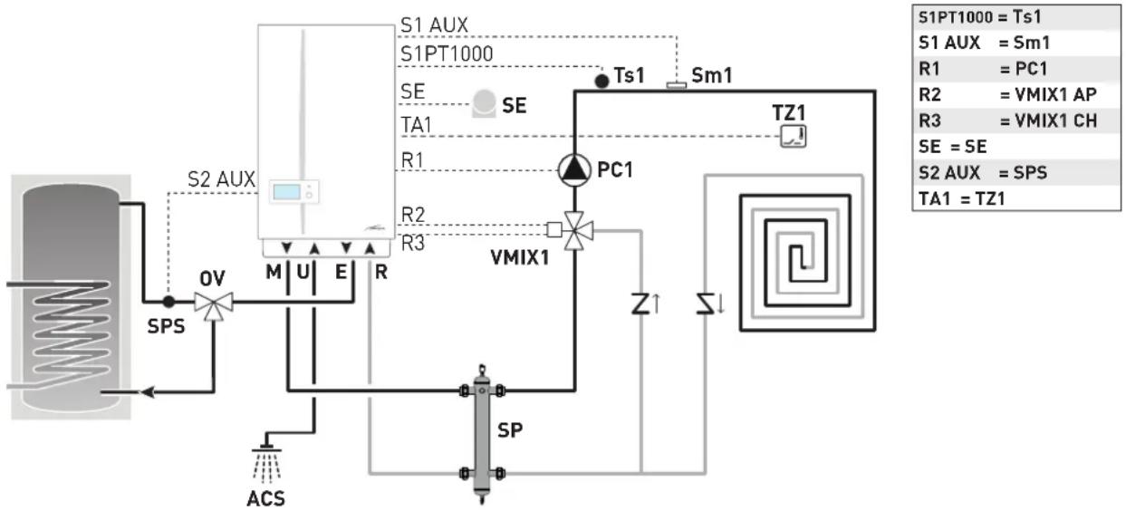
flowchart
graph TD
    A["ACS"] --> B["Ov"]
    B --> C["M U E R"]
    C --> D["S2 AUX"]
    D --> E["S1 AUX"]
    E --> F["S1PT1000"]
    F --> G["SE TA1"]
    G --> H["SE"]
    H --> I["PC1"]
    I --> J["TZ1"]
    J --> K["VMIX1"]
    K --> L["Z↑"]
    L --> M["SP"]
    M --> N["ACS"]
    N --> O["SPS"]
    O --> P["S1PT1000 = Ts1"]
    P --> Q["S1 AUX = Sm1"]
    Q --> R["R1 = PC1"]
    R --> S["R2 = VMIX1 AP"]
    S --> T["R3 = VMIX1 CH"]
    T --> U["SE = SE"]
    U --> V["S2 AUX = SPS"]
    V --> W["TA1 = TZ1"]
M System delivery
U Domestic hot water output
E Domestic hot water inlet
R Boiler return
DHW Domestic hot water
SE External temperature sensor
OV Thermostatic diverter mixer
PC1 Circuit pump 1
VMIX1 Mixer valve circuit 1
Sm1 Circuit 1 delivery sensor
Ts1 Circuit 1 safety thermostat
TZ1 Zone thermostat
Vz Zone valve
SPS Domestic hot water preheating sensor
SP Hydraulic separator
Solution 6: System with two direct multi-zone circuits and a remote hot water tank for preheating domestic hot water
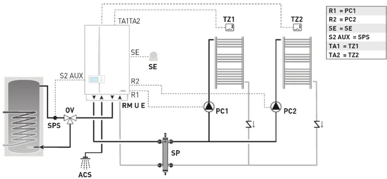
flowchart
graph TD
    A["Reactor"] --> B["SPS"]
    B --> C["Ov"]
    C --> D["SP"]
    D --> E["ACS"]
    E --> F["RM U E"]
    F --> G["TP1"]
    G --> H["PC1"]
    H --> I["TP2"]
    I --> J["PC2"]
    J --> K["TZ1"]
    K --> L["TZ2"]
    L --> M["TA1"]
    M --> N["TZ1"]
    N --> O["TA2"]
    O --> P["TZ2"]
    P --> Q["R1 = PC1"]
    P --> R["R2 = PC2"]
    P --> S["SE = SE"]
    P --> T["S2 AUX = SPS"]
    P --> U["TA1 = TZ1"]
    P --> V["TA2 = TZ2"]
M System delivery
U Domestic hot water output
E Domestic hot water inlet
R Boiler return
DHW Domestic hot water
SE External temperature sensor
ov Thermostatic diverter mixer
PC1 Direct circuit pump 1
PC2 Direct circuit pump 2
TZ1-2 Zone thermostat
SPS Domestic hot water preheating sensor
SP Hydraulic separator
Solution 8: System with one direct multi-zone circuit and a remote solar hot water tank for preheating domestic hot water
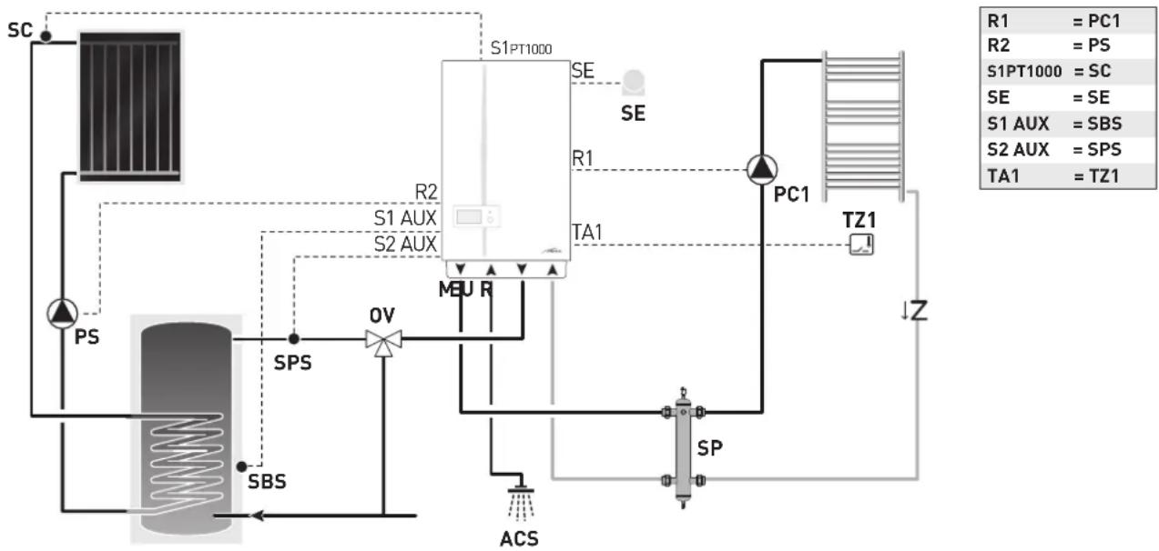
flowchart
graph TD
    SC["SC"] -->|Input| Sensor1["Sensor"]
    Sensor1 -->|Output| S1PT1000["S1PT1000"]
    Sensor1 -->|Output| S2AUX["S2 AUX"]
    Sensor1 -->|Output| MEU_R["MEU R"]
    Sensor1 -->|Output| SPS["SPS"]
    Sensor1 -->|Output| OV["OV"]
    Sensor1 -->|Output| SBS["SBS"]
    Sensor1 -->|Output| ACS["ACS"]
    Sensor1 -->|Output| SP["SP"]
    Sensor1 -->|Output| Z["Z"]
    R2["R2"] --> S1AUX["S1 AUX"]
    R2 --> S2AUX["S2 AUX"]
    R1["R1"] --> MEU_R
    R1 --> MEU_R
    R1 --> TA1["TA1"]
    R2 --> PC1["PC1"]
    PC1 --> TZ1["TZ1"]
    TZ1 --> Z
    style SC fill:#f9f,stroke:#333
    style Sensor1 fill:#ccf,stroke:#333
    style S1PT1000 fill:#cfc,stroke:#333
    style S2AUX fill:#fcc,stroke:#333
    style MEU_R fill:#cff,stroke:#333
    style MEU_R fill:#ffc,stroke:#333
    style SPS fill:#cfc,stroke:#333
    style OV fill:#ffc,stroke:#333
    style SBS fill:#cfc,stroke:#333
    style ACS fill:#fcc,stroke:#333
    style SP fill:#cfc,stroke:#333
    style Z fill:#fcc,stroke:#333
    note right of R1 = PC1
    note right of R2 = PS
    note right of S1PT1000 = SC
    note right of SE = SE
    note right of S1 AUX = SBS
    note right of S2 AUX = SPS
    note right of TA1 = TZ1
M System delivery
U Domestic hot water output
E Domestic hot water inlet
R Boiler return
DHW Domestic hot water
SE External temperature sensor
OV Thermostatic diverter mixer
PC1 Direct circuit pump 1
TZ1 Zone thermostat
Vz Zone valve
PS Solar pump
SBS Solar hot water tank sensor
SC Solar manifold probe
SPS Domestic hot water preheating sensor
SP Hydraulic separator
Solution 9: System with a mixed multi-zone circuit and a remote solar hot water tank for preheating domestic hot water
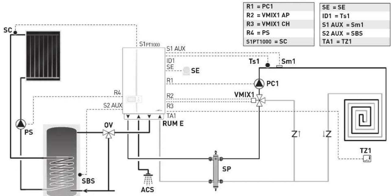
flowchart
graph TD
    A["SC"] --> B["PS"]
    B --> C["SBS"]
    C --> D["Ov"]
    D --> E["R4"]
    E --> F["S2 AUX"]
    F --> G["S1 PT1000"]
    G --> H["S1 AUX"]
    H --> I["ID1 SE"]
    I --> J["SE"]
    J --> K["PC1"]
    K --> L["VMIX1"]
    L --> M["Z1"]
    M --> N["TZ1"]
    O["ACS"] --> P["SP"]
    P --> Q["Z1"]
    Q --> R["TZ1"]
    S["TS1"] --> T["Sm1"]
    U["S1 PT1000 = SC"] --> V["SE = SE"]
    W["S2 AUX = SBS"] --> X["S1 AUX = Sm1"]
    Y["SAI = TS1"] --> Z["S2 AUX = SM1"]
    AA["SAI = TS1"] --> AB["S2 AUX = SM1"]
M System delivery
U Domestic hot water output
E Domestic hot water inlet
R Boiler return
DHW Domestic hot water
SE External temperature sen-
sor
OV Thermostatic diverter mixer
PC1 Circuit pump 1
VMIX1 Mixer valve circuit 1
Sm1 Circuit 1 delivery sensor
Ts1 Circuit 1 safety thermostat
TZ1 Zone thermostat
Vz Zone valve
SBS Solar hot water tank sensor
sc Solar manifold probe
PS Solar pump
SP Hydraulic separator
Solution 10: System with instant boiler with one direct multi-zone circuit, a mixed multi-zone circuit and a remote solar hot water tank for preheating domestic hot water
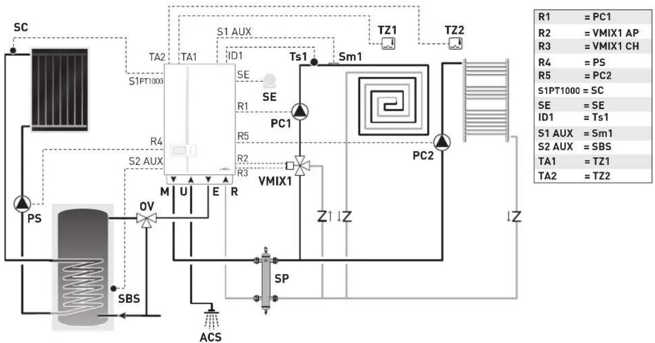
flowchart
graph TD
    SC["SC"] --> TA2["TA1"]
    TA2 --> S1PT1000["S1PT1000"]
    TA1 --> ID1["ID1"]
    ID1 --> S1AUX["S1 AUX"]
    S1AUX --> Tz1["TZ1"]
    Tz1 --> Tz2["Tz2"]
    Tz2 --> SM1["Sm1"]
    SM1 --> Ts1["Ts1"]
    Ts1 --> R4["R4"]
    R4 --> S2AUX["S2 AUX"]
    S2AUX --> OV["OV"]
    OV --> M["M"]
    M --> U["U"]
    U --> E["E"]
    E --> R["R"]
    R --> R3["R3"]
    R3 --> VIMIX1["VMIX1"]
    VIMIX1 --> Z1["Z"]
    Z1 --> PC2["PC2"]
    PC2 --> Z
    Z --> SP["SP"]
    SP --> ACS["ACS"]
    PS["PS"] --> OV
    OV --> SBS["SBS"]
    SBS --> TA2_2["TA2 = TZ2"]
    style SC fill:#f9f,stroke:#333
    style TA2 fill:#ccf,stroke:#333
    style S1PT1000 fill:#dfd,stroke:#333
    style S1AUX fill:#dfd,stroke:#333
    style S2AUX fill:#dfd,stroke:#333
    style TA2 fill:#dfd,stroke:#333
    style TA2_2 fill:#dfd,stroke:#333
M System delivery
U Domestic hot water output
E Domestic hot water inlet
R Boiler return
DHW Domestic hot water
SE External temperature sen-
sor
0V Thermostatic diverter mixer
PC1 Circuit pump 1
PC2 Direct circuit pump 2
VMIX1 Mixer valve circuit 1
Sm1 Circuit 1 delivery sensor
Ts1 Circuit 1 safety thermostat
TZ1-2 Zone thermostat
SBS Solar hot water tank sensor
sc Solar manifold probe
PS Solar pump
SP Hydraulic separator
Solution 12: System with one direct multi-zone circuit and a hot/cold mode system
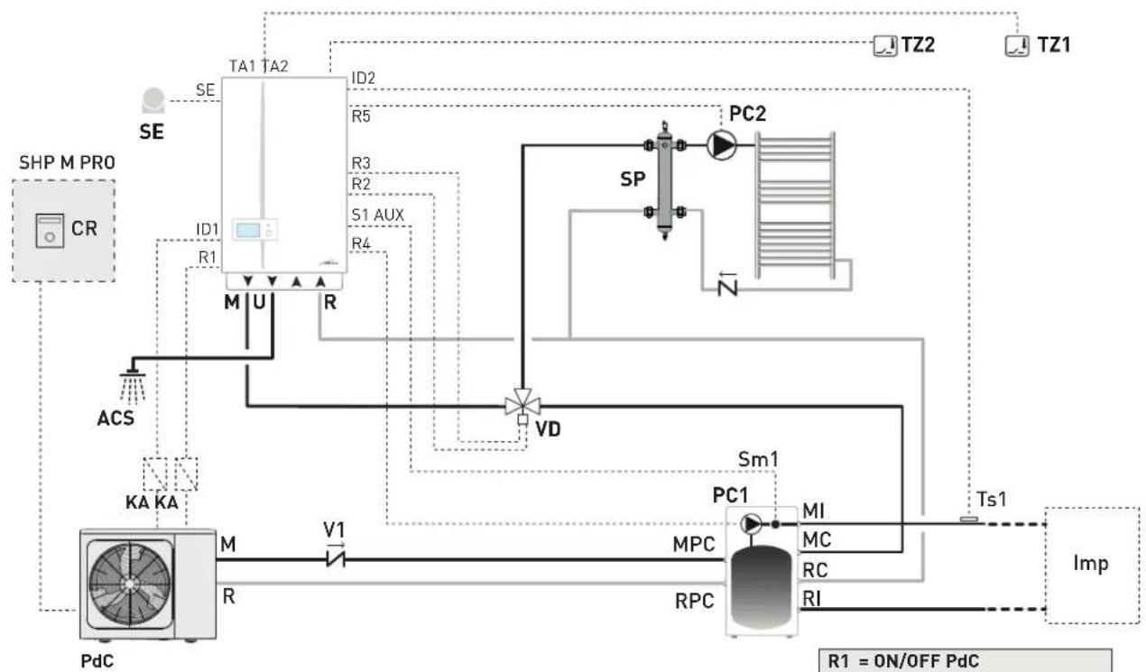
flowchart
graph TD
    A["SHP M PRO"] -->|SE| B["TA1 TA2"]
    A -->|ID1 R1| C["M U R"]
    B --> D["ID2 R5"]
    B --> E["R3 R2"]
    B --> F["S1 AUX R4"]
    C --> G["M"]
    D --> H["PC2"]
    E --> I["VD"]
    F --> J["SP"]
    J --> K["RC"]
    K --> L["Ts1"]
    L --> M["Imp"]
    N["KA KA"] --> O["PdC"]
    O --> P["M"]
    P --> Q["V1"]
    Q --> R["MPC"]
    R --> S["RPC"]
    S --> T["MI"]
    S --> U["MC"]
    S --> V["RC"]
    S --> W["RI"]
    X["TZ2"] --> Y["TZ1"]
    Z["ACS"] --> AA["M"]
    AB["VT"] --> AC["VD"]
    AD["SM1"] --> AE["PC1"]
    AF["R1 = ON/OFF PdC"] --> AG["Ts1"]
| CONNECTIONS TO TERMINALS | ||
| SHP ECO EV | SHP M PRO | |
| ON/OFF PdC(Heat Pump) | 15.1-15.2 | HT-COM (CN31) |
| CR PdC(Heat Pump) | ---- | HA-HB (CN30) |
| ALARM PdC(Heat Pump) | 14.1-14.2 | 23-24 (CN11) |
| R1 = ON/OFF PdC |
| R2 = VD AP |
| R3 = VD CH |
| R4 = PC1 |
| R5 = PC2 |
| TA1 = TZ1 |
| TA2 = TZ2 |
| SE = SE |
| ID1 = ALARM PdC |
| ID2 = Ts1 |
| S1 AUX = Sm1 |
M Boiler delivery
U Domestic hot water output
R Boiler return
PC1 Direct circuit pump 1
PC2 Direct circuit pump 2
TZ1-2 Zone ambient thermostat
SP Hydraulic separator
PdC Heat pump
MI System delivery
MC Boiler delivery
RI System return
RC Boiler return
MPC Heat pump delivery
RPC Heat pump return
V1 Check valve
VD Diverter valve
Sm1 Circuit 1 delivery sensor
Ts1 Circuit 1 safety thermostat
CR Remote control
KA Relè
Syst Systems
PARAMETER SETTINGS REQUIRED FOR HEAT PUMP
The settings required for the optimal operation of the generators and systems, and for guaranteeing the utmost comfort for the user, include:
SHP ECO EV Heat Pump
- modify PAR H85 = 24
SHP M PRO Heat Pump
- modify PAR 6.1 = ONE ZONE
- modify PAR 1.1 = NO
- modify PAR 15.5 = ALARM

CAUTION
The password for the Assistance Service is "234".

CAUTION
If the "SHP M PRO" heat pump is installed with the finned battery facing SOUTH, pay attention to PAR 3.3 which must be increased to the maximum value of 35^ (the value set by default is 25^ ).
Solution 14: System with one mixed multi-zone circuit, a fan coil and a hot/cold mode system
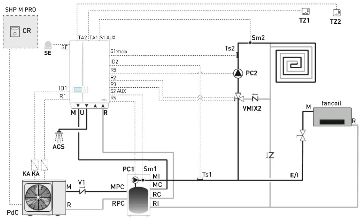
flowchart
graph TD
    subgraph fancoil_fancoil
        M["fancoil"] --> R["R"]
        M -->|M| KA["KA KA"]
        KA -->|M| V1["V1"]
        V1 --> MPC["MPC"]
        MPC --> RPC["RPC"]
        MPC --> SM1["Sm1"]
        SM1 -->|MI| RC["RC"]
        SM1 -->|MC| MPC
        SM1 -->|MI| V1
        SM1 -->|MC| MPC
        SM1 -->|MI| RPC
        SM1 -->|MC| V1
        SM1 -->|MI| RPC
        SM1 -->|MC| PC1["PC1"]
        PC1 -->|Ts1| V1
        PC1 -->|Ts2| PC2["PC2"]
        PC2 -->|N| VMIX2["VMIX2"]
        VMIX2 -->|S2 AUX| S2_AUX["R4"]
        VMIX2 -->|R5| ID2["ID2"]
        VMIX2 -->|R3| ID3["R3"]
        VMIX2 -->|R2| ID4["R2"]
        VMIX2 -->|R1| ID1["ID1"]
        VMIX2 -->|R1| ID_R["RE"]
        VMIX2 -->|R1| ID_S["SE"]
        VMIX2 -->|R1| ID_T["SE"]
        VMIX2 -->|R1| ID_U["U"]
        VMIX2 -->|R1| ID_V["R"]
        VMIX2 -->|R1| ID_W["S1 AUX"]
        VMIX2 -->|R1| ID_X["S1PT1000"]
        VMIX2 -->|R1| ID_Y["ID2"]
        VMIX2 -->|R1| ID_Z["ID1"]
        VMIX2 -->|R1| ID_A["ID1"]
        VMIX2 -->|R1| ID_B["ID1"]
        VMIX2 -->|R1| ID_C["ID1"]
    end
    subgraph fancoil_fancooil_tilde
        Tz1["Tz1"] --> SM2["Sm2"]
        Tz2["Tz2"] --> Sm2
    end
    subgraph fancoil_fancooil_silde
        E["I"] --> F["Z"]
        E["I"] --> G["E/I"]
    end
| CONNECTIONS TO TERMINALS | ||
| SHP ECO EV | SHP M PRO | |
| ON/OFF PdC(Heat Pump) | 15.1-15.2 | HT-COM (CN31) |
| CR PdC(Heat Pump) | ---- | HA-HB (CN30) |
| ALARM PdC(Heat Pump) | 14.1-14.2 | 23-24 (CN11) |
| R1 = ON/OFF PdC |
| R2 = VMIX2 AP |
| R3 = VMIX2 AC |
| R4 = PC1 |
| R5 = PC2 |
| TA1 = TZ1 |
| TA2 = TZ2 (*) |
| S1PT1000 = Ts2 |
| SE = SE |
| ID1 = ALARM PdC |
| ID2 = Ts1 |
| S1 AUX = Sm2 |
| S2 AUX = Sm1 |
| (*) = ON / OFF Fancoil |
M Boiler delivery
U Domestic hot water output
R Boiler return
PC1 Direct circuit pump 1
PC2 Direct circuit pump 2
TZ1-2 Zone ambient thermostat
E/I Manual valve (summer/winter)
PdC Heat pump
MI System delivery
MC Boiler delivery
RI System return
RC Boiler return
MPC Heat pump delivery
RPC Heat pump return
V1 Check valve
Sm1 Circuit 1 delivery sensor
Sm2 Circuit 2 delivery sensor
Ts1 Circuit 1 safety thermostat
Ts2 Circuit 2 safety thermostat
VMIX2 Mixer valve circuit 2
CR Remote control
KA Relè
PARAMETER SETTINGS REQUIRED FOR HEAT PUMP
The settings required for the optimal operation of the generators and systems, and for guaranteeing the utmost comfort for the user, include:
SHP ECO EV Heat Pump
- modify PAR H85 = 24
SHP M PRO Heat Pump
- modify PAR 6.1 = ONE ZONE
- modify PAR 1.1 = NO
- modify PAR 15.5 = ALARM

CAUTION
The password for the Assistance Service is "234".

CAUTION
If the "SHP M PRO" heat pump is installed with the finned battery facing SOUTH, pay attention to PAR 3.3 which must be increased to the maximum value of 35^ (the value set by default is 25^ ).
Solution 15: System with one direct multi-zone circuit, a remote solar hot water tank for preheating domestic hot water, and a hot/cold mode system
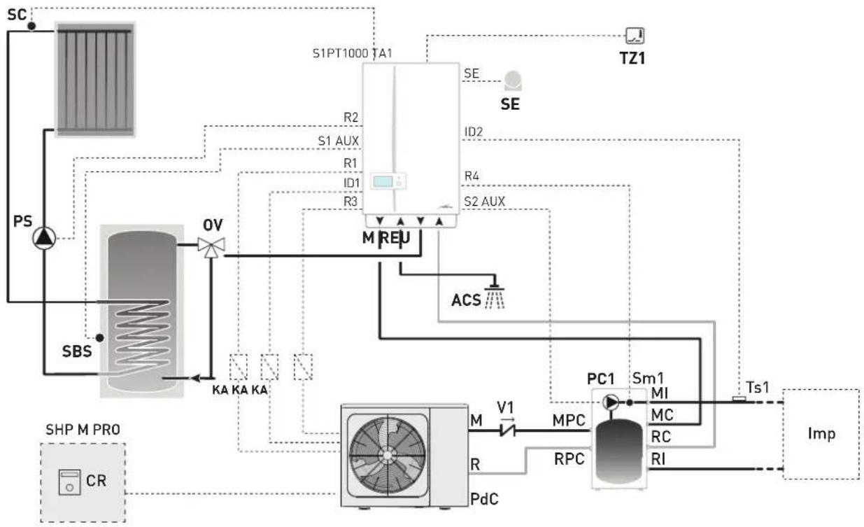
flowchart
graph TD
    SC["SC"] --> PS["PS"]
    PS --> SBS["SBS"]
    SBS --> OV["OV"]
    OV --> KA["KA KA KA"]
    KA --> SHP_M_PRO["SHP M PRO"]
    SHP_M_PRO --> CR["CR"]
    SHP_M_PRO --> MPC["MPC"]
    MPC --> RPC["RPC"]
    MPC --> PdC["PdC"]
    MPC --> PC1["PC1"]
    PC1 --> Sm1["Sm1"]
    Sm1 --> MI["MI"]
    Sm1 --> MC["MC"]
    Sm1 --> RC["RC"]
    Sm1 --> RI["RI"]
    PC1 --> Tz1["Tz1"]
    Tz1 --> SE["SE"]
    SE --> ID2["ID2"]
    ID2 --> R4["R4"]
    R4 --> S2_AUX["S2 AUX"]
    S2_AUX --> M_REU["M REU"]
    M_REU --> ACS["ACS"]
    ACS --> PC1
    PC1 --> Ts1["Ts1"]
    Ts1 --> Imp["Imp"]
    SPT1000_TA1["S1PT1000 TA1"] --> R2["R2"]
    SPT1000_TA1 --> R1["R1"]
    SPT1000_TA1 --> ID1["ID1"]
    SPT1000_TA1 --> R3["R3"]
    SPT1000_TA1 --> ID2["ID2"]
    SPT1000_TA1 --> R4["R4"]
    SPT1000_TA1 --> ID3["ID3"]
| CONNECTIONS TO TERMINALS | ||
| SHP ECO EV | SHP M PRO | |
| ON/OFF PdC(Heat Pump) | 15.1-15.2 | HT-COM (CN31) |
| CR PdC(Heat Pump) | ---- | HA-HB (CN30) |
| ALARM PdC(Heat Pump) | 14.1-14.2 | 23-24 (CN11) |
| SUMMER/WINTER* | 16.1-16.2 | ---- |
| R1 = ON/OFF PdC |
| R2 = PS |
| R3 = PdC (E/I) |
| R4 = PC1 |
| PT1000 = SC |
| SE = SE |
| ID1 = ALARM PdC [***] |
| ID2 = Ts1 |
| TA1 = TZ1 |
| S1 AUX = SBS |
| S2 AUX = Sm1S1 |
| M Boiler delivery | MI | System delivery | Sm1 | Circuit 1 delivery sensor | |
| U Domestic hot water output | MC | Boiler delivery | Ts1 | Circuit 1 safety thermostat | |
| E | Domestic hot water inlet | RI | System return | CR | Remote control |
| R Boiler return | RC | Boiler return | KA | Relè | |
| DHW | Domestic hot water | MPC | Heat pump delivery | TZ1 | Zone ambient thermostat |
| SE | External sensor | RPC | Heat pump return | Syst | Systems |
| OV | Thermostatic diverter mixer | V1 | Check valve | ||
| PC1 | Direct circuit pump 1 | PS | Solar pump | (***) | Alarm |
| PdC | Heat pump | SBS | Solar hot water tank sensor | ||
| SC | Solar manifold probe | ||||
PARAMETER SETTINGS REQUIRED FOR HEAT PUMP
The settings required for the optimal operation of the generators and systems, and for guaranteeing the utmost comfort for the user, include:
SHP ECO EV Heat Pump
- modify PAR H85 = 24
- modify PAR H46 = 3
SHP M PRO Heat Pump
- modify PAR 6.1 = ONE ZONE
- modify PAR 1.1 = NO
- modify PAR 15.5 = ALARM

CAUTION
The password for the Assistance Service is "234".

CAUTION
If the "SHP M PRO" heat pump is installed with the finned battery facing SOUTH, pay attention to PAR 3.3 which must be increased to the maximum value of 35^ (the value set by default is 25^ ).
6.14.3 Plant solution diagrams with wireless room probes and radio-frequency receiver
Solution 1: System with two direct multi-zone circuits
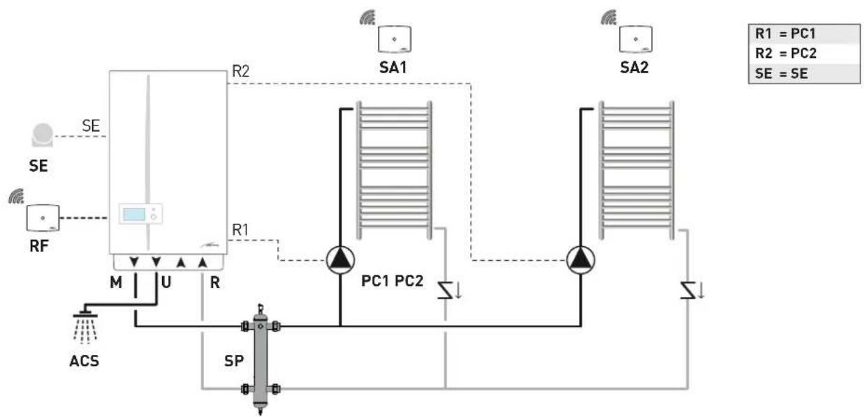
flowchart
graph TD
    SE["Power Source"] --> RF["RF"]
    RF --> M["M"]
    M --> U["U"]
    U --> R["R"]
    R --> R1["R1"]
    R1 --> SA1["SA1"]
    SA1 --> PC1["PC1"]
    SA1 --> PC2["PC2"]
    SA2["SA2"] --> PC1
    SA2 --> PC2
    PC1 --> S1["S"]
    PC2 --> S2["S"]
    S1 --> SP["SP"]
    S2 --> SP
    R2["R2"] --> SA1
    R2 --> SA2
    style SE fill:#f9f,stroke:#333
    style RF fill:#ccf,stroke:#333
    style PC1 fill:#cfc,stroke:#333
    style PC2 fill:#cfc,stroke:#333
    style S1 fill:#fcc,stroke:#333
    style S2 fill:#fcc,stroke:#333
M System delivery
U Domestic hot water output
R Boiler return
DHW Domestic hot water
SE External temperature sensor
PC1 Direct circuit pump 1
PC2 Direct circuit pump 2
SP Hydraulic separator
SA1-2 Wireless room probe
RF Radio-frequency receiver
Solution 2: System a mixed multi-zone circuit
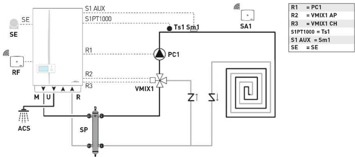
flowchart
graph TD
    A["SE"] --> B["S1 AUX"]
    B --> C["S1PT1000"]
    C --> D["Ts1 Sm1"]
    D --> E["SA1"]
    F["RF"] --> G["M U R"]
    G --> H["ACS"]
    I["PC1"] --> J["VMIX1"]
    K["SP"] --> L["Ground"]
    M["R1"] --> N["Ground"]
    O["R2"] --> P["Ground"]
    Q["R3"] --> R["Ground"]
    S["Z↑"] --> T["Square coil"]
    U["SE = SE"] --> V["SA1"]
    W["R1 = PC1"] --> X["SA1"]
    Y["R2 = VMIX1 AP"] --> Z["SA1"]
    AA["R3 = VMIX1 CH"] --> AB["SA1"]
    AC["S1PT1000 = Ts1"] --> AD["SA1"]
    AE["S1 AUX = Sm1"] --> AF["SA1"]
M System delivery
U Domestic hot water output
R Boiler return
DHW Domestic hot water
SE External temperature sensor
PC1 Circuit pump 1
VMIX1 Mixer valve circuit 1
Sm1 Circuit 1 delivery sensor
Ts1 Circuit 1 safety thermostat
SP Hydraulic separator
SA1 Wireless room probe
RF Radio-frequency receiver
Solution 3: System with a direct multi-zone circuit and a mixed multi-zone circuit
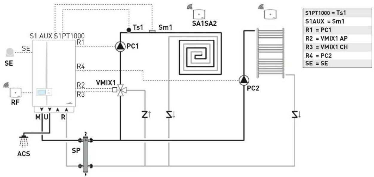
flowchart
graph TD
    A["SE"] --> B["S1 AUX S1PT1000"]
    B --> C["PC1"]
    C --> D["SA1SA2"]
    D --> E["PC2"]
    E --> F["ACS"]
    F --> G["SP"]
    G --> H["M U R"]
    H --> I["R4"]
    I --> J["VMIX1"]
    J --> K["Z↑"]
    K --> L["Σ↓"]
    L --> M["SA1SA2"]
    M --> N["PC2"]
    N --> O["ACS"]
    style A fill:#f9f,stroke:#333
    style B fill:#ccf,stroke:#333
    style C fill:#cfc,stroke:#333
    style D fill:#fcc,stroke:#333
    style E fill:#cff,stroke:#333
    style F fill:#ffc,stroke:#333
    style G fill:#cfc,stroke:#333
    style H fill:#fcc,stroke:#333
    style I fill:#cfc,stroke:#333
    style J fill:#cfc,stroke:#333
    style K fill:#cfc,stroke:#333
    style L fill:#cfc,stroke:#333
    style M fill:#cfc,stroke:#333
    style N fill:#cfc,stroke:#333
M System delivery
U Domestic hot water output
R Boiler return
SE External temperature sensor
PC1 Circuit pump 1
PC2 Direct circuit pump 2
VMIX1 Mixer valve circuit 1
Sm1 Circuit 1 delivery sensor
Ts1 Circuit 1 safety thermostat
SP Hydraulic separator
SA1-2 Wireless room probe
RF Radio-frequency receiver
Solution 5: System with a mixed multi-zone circuit and a remote hot water tank for preheating domestic hot water
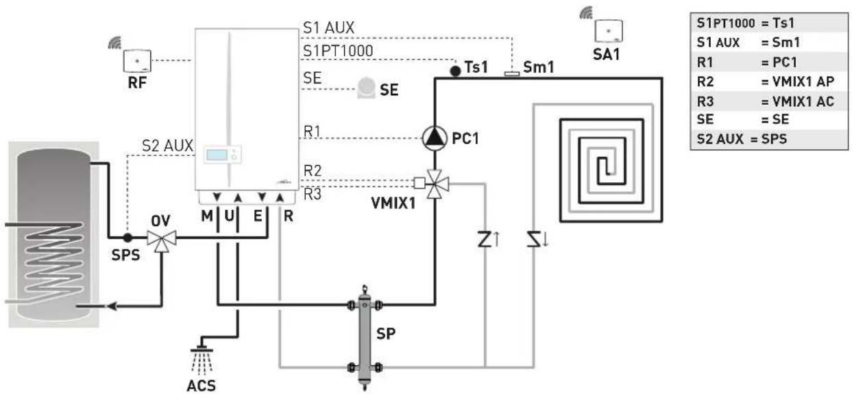
flowchart
graph TD
    A["RF"] --> B["S1 AUX"]
    B --> C["S1PT1000"]
    C --> D["SE"]
    D --> E["SE"]
    E --> F["Ts1"]
    F --> G["Sm1"]
    G --> H["SA1"]
    I["S2 AUX"] --> J["OV"]
    J --> K["M U E R"]
    K --> L["SP"]
    M["SPS"] --> N["ACS"]
    O["VMIX1"] --> P["Z1"]
    P --> Q["SI"]
    Q --> R["SI"]
    S["RC"] --> T["R1, R2, R3"]
    T --> U["PC1"]
    U --> V["SA1"]
    W["S1PT1000 = Ts1"] --> X["S1 AUX = Sm1"]
    Y["R1 = PC1"] --> Z["R2 = VMIX1 AP"]
    AA["R3 = VMIX1 AC"] --> AB["SE = SE"]
    AC["S2 AUX = SPS"] --> AD["SI"]
M System delivery
U Domestic hot water output
E Domestic hot water inlet
R Boiler return
SE External temperature sensor
OV Thermostatic diverter mixer
PC1 Circuit pump 1
VMIX1 Mixer valve circuit 1
Sm1 Circuit 1 delivery sensor
Ts1 Circuit 1 safety thermostat
Vz Zone valve
SPS Domestic hot water preheating sensor
SP Hydraulic separator
SA1-2 Wireless room probe
RF Radio-frequency receiver
Solution 6: System with two direct multi-zone circuits and a remote hot water tank for preheating domestic hot water
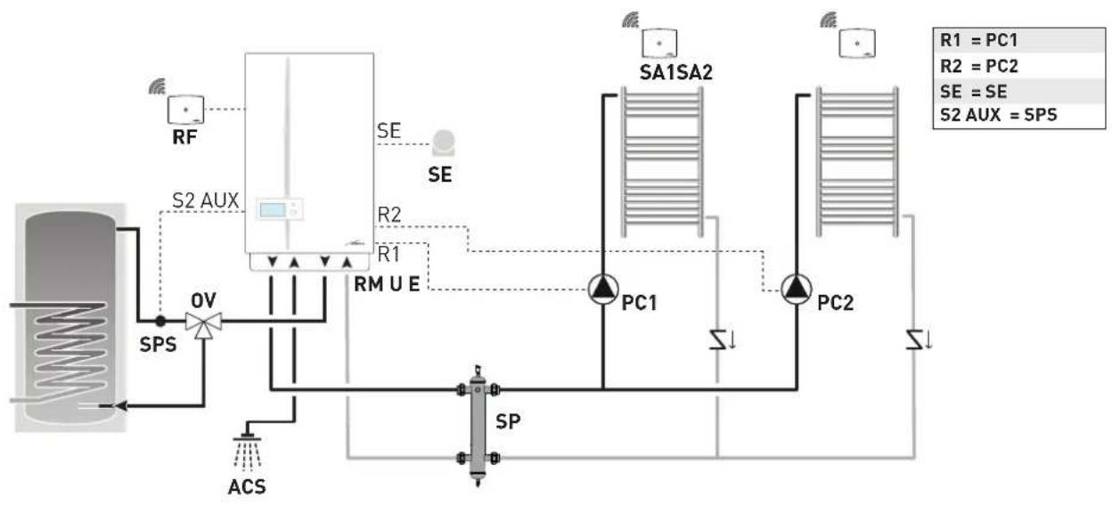
flowchart
graph TD
    A["Reactor"] --> B["S2 AUX"]
    B --> C["RF"]
    C --> D["Sensor"]
    D --> E["Ov"]
    E --> F["SPS"]
    F --> G["ACS"]
    G --> H["Sp"]
    H --> I["RM U E"]
    I --> J["SE"]
    J --> K["SA1SA2"]
    K --> L["PC1"]
    K --> M["PC2"]
    L --> N["SI"]
    M --> O["SI"]
    style A fill:#f9f,stroke:#333
    style K fill:#ccf,stroke:#333
    style L fill:#cfc,stroke:#333
M System delivery
U Domestic hot water output
E Domestic hot water inlet
R Boiler return
SE External temperature sensor
OV Thermostatic diverter mixer
PC1 Direct circuit pump 1
PC2 Direct circuit pump 2
SPS Domestic hot water preheating sensor
SP Hydraulic separator
SA1-2 Wireless room probe
RF Radio-frequency receiver
Solution 8: System with one direct multi-zone circuit and a remote solar hot water tank for preheating domestic hot water
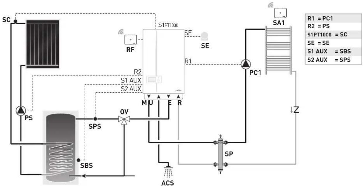
flowchart
graph TD
    SC["SC"] -->|RSU| PS["PS"]
    PS --> SPS["SPS"]
    SPS --> OV["OV"]
    OV --> M["U"]
    M --> E["E"]
    E --> R["R"]
    R --> S2["AUX"]
    S2 -->|R1| PC1["PC1"]
    PC1 --> Z["Z"]
    R1 --> SA1["SA1"]
    SA1 -->|RSU| R2["RS2"]
    R2 -->|RSU| S1AUX["S1 AUX"]
    S1AUX -->|RSU| S2AUX["S2 AUX"]
    S2AUX -->|RSU| S1PT1000["S1 PT1000"]
    S1PT1000 -->|RSU| R2
    R2 -->|RSU| S1PT1000
    R2 -->|RSU| SE["SE"]
    SE -->|RSU| R1
    R1 -->|RSU| SA1
    SA1 -->|RSU| R1
    style SC fill:#f9f,stroke:#333
    style PA fill:#ccf,stroke:#333
    style PS fill:#cfc,stroke:#333
    style OV fill:#fcc,stroke:#333
    style V fill:#cff,stroke:#333
    style AC fill:#ffc,stroke:#333
    style SP fill:#cfc,stroke:#333
    style Z fill:#fcc,stroke:#333
    style SA1 fill:#fff,stroke:#333
    style R2 fill:#fff,stroke:#333
    style S1AUX fill:#fff,stroke:#333
    style S2AUX fill:#fff,stroke:#333
M System delivery
U Domestic hot water output
E Domestic hot water inlet
R Boiler return
SE External temperature sensor
OV Thermostatic diverter mixer
PC1 Direct circuit pump 1
Vz Zone valve
PS Solar pump
SBS Solar hot water tank sensor
sc Solar manifold probe
SPS Domestic hot water preheating sensor
SP Hydraulic separator
SA1-2 Wireless room probe
RF Radio-frequency receiver
Solution 9: System with a mixed multi-zone circuit and a remote solar hot water tank for preheating domestic hot water
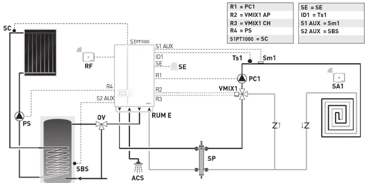
flowchart
graph TD
    SC["SC"] --> RF["RF"]
    RF --> S1PT1000["S1PT1000"]
    S1PT1000 --> S1AUX["S1 AUX"]
    S1AUX --> ID1["ID1"]
    S1AUX --> SE["SE"]
    S1AUX --> R1["R1"]
    S1AUX --> R2["R2"]
    S1AUX --> R3["R3"]
    S1AUX --> S2AUX["S2 AUX"]
    S2AUX --> OV["OV"]
    OV --> RUME["RUM E"]
    RUME --> PC1["PC1"]
    PC1 --> VIMIX1["VMIX1"]
    VIMIX1 --> S1AUX_Sm1["S1 AUX = Sm1"]
    VIMIX1 --> S2AUX_SBS["S2 AUX = SBS"]
    S2AUX_SBS --> SBS["SBS"]
    SBS --> ACS["ACS"]
    ACS --> SP["SP"]
    PS["PS"] --> OV
    S1PT1000 --> Ts1["Ts1"]
    Ts1 --> Sm1["Sm1"]
    SM1 --> PC1
    PC1 --> Z1["Z1"]
    Z1 --> SA1["SA1"]
    SA1 --> Z["Z"]
    Z --> AC["ACS"]
    AC --> SP
    style SC fill:#f9f,stroke:#333
    style RF fill:#ccf,stroke:#333
    style S1PT1000 fill:#cfc,stroke:#333
    style S2AUX fill:#fcc,stroke:#333
    style PC1 fill:#cff,stroke:#333
    style VIMIX1 fill:#ffc,stroke:#333
    style S1AUX_Sm1 fill:#cfc,stroke:#333
    style S2AUX_SBS fill:#cfc,stroke:#333
M System delivery
U Domestic hot water output
E Domestic hot water inlet
R Boiler return
DHW Domestic hot water
SE External temperature sen-
sor
OV Thermostatic diverter mixer
PC1 Circuit pump 1
VMIX1 Mixer valve circuit 1
Sm1 Circuit 1 delivery sensor
Ts1 Circuit 1 safety thermostat
Vz Zone valve
SBS Solar hot water tank sensor
sc Solar manifold probe
PS Solar pump
SP Hydraulic separator
SA1-2 Wireless room probe
RF Radio-frequency receiver
Solution 10: System with instant boiler with one direct multi-zone circuit, a mixed multi-zone circuit and a remote solar hot water tank for preheating domestic hot water
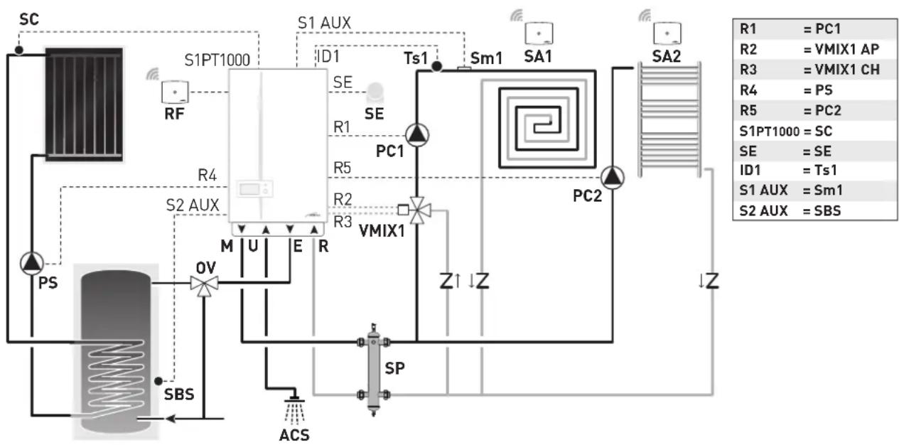
flowchart
graph TD
    SC["SC"] --> RF["RF"]
    RF --> S1PT1000["S1PT1000"]
    S1PT1000 --> S1AUX["S1 AUX"]
    S1AUX --> ID1["ID1"]
    ID1 --> SE["SE"]
    SE --> PC1["PC1"]
    PC1 --> R1["R1"]
    R1 --> R5["R5"]
    R5 --> R2["R2"]
    R2 --> R3["R3"]
    R3 --> VMIX1["VMIX1"]
    VMIX1 --> PC2["PC2"]
    PC2 --> Z1["Z1"]
    Z1 --> Z["Z"]
    Z --> ZZ["Z"]
    ZZ --> S2AUX["S2 AUX"]
    S2AUX --> PS["PS"]
    PS --> OV["OV"]
    OV --> M["M"]
    M --> U["U"]
    U --> E["E"]
    E --> R["R"]
    R --> R4["R4"]
    R4 --> S2AUX
    S2AUX --> SBS["SBS"]
    SBS --> ACS["ACS"]
    SBS --> SP["SP"]
    SBS --> Z["ACS"]
    SBS --> ZZ["ACS"]
    SBS --> SM1["Sm1"]
    SBS --> SA1["SA1"]
    SBS --> SA2["SA2"]
    SM1 --> Ts1["Ts1"]
    SA1 --> Sm1["Sm1"]
    SA2 --> SM2["SM2"]
M System delivery
U Domestic hot water output
E Domestic hot water inlet
R Boiler return
DHW Domestic hot water
SE External temperature sen-
sor
OV Thermostatic diverter mixer
PC1 Circuit pump 1
PC2 Direct circuit pump 2
VMIX1 Mixer valve circuit 1
Sm1 Circuit 1 delivery sensor
Ts1 Circuit 1 safety thermostat
SBS Solar hot water tank sensor
sc Solar manifold probe
PS Solar pump
SP Hydraulic separator
SA1-2 Wireless room probe
RF Radio-frequency receiver
6.15 Displaying the set system solution
From the "Main screen":
- turn the encoder to select the "Menu" (Menu) function and press the click encoder to enter the "Menu" (Menu) selection screen
- turn the encoder to select the "TECHNICAL"(Technical) menu
![Mon 01.01.2018 10:30 75°C 55°C 65°C 25% 11°C 1.5 Menu Mode Zones Menu GENERAL SETTINGS [...] INFORMATION [...] TECHNICAL Fig. 55](/content/2026/05/855257/images/a532fa071f60d24ee1ea90f20358579c0125b1c862648fba1eb7adf36ff693cd.jpg)
- press the click encoder and select "Confirm" (Confirm), press the click encoder to confirm
- turn the encoder to select the "Plant solution" (Plant solution) item
![TECHNICAL Confirm operation Confirm TECHNICAL Information [...] Plant solution Technician param. [...] Chimney sweeper [...] IoT [...] Fig. 56](/content/2026/05/855257/images/c469e507dea028a5740d6dda526af90c9daec59215312e34a8a6ecaf5048d93c.jpg)
- press the click encoder to open the "Plant solution" (Plant solution) screen and display the system solution set.
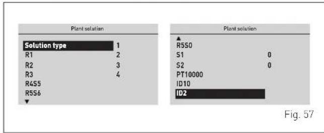
6.16 Refilling or emptying
Before carrying out the operation described below, make sure that the main system switch is set to "OFF".
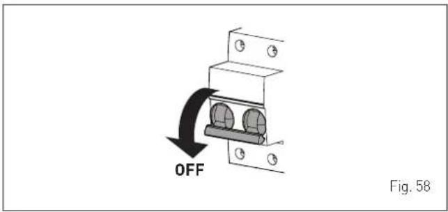
6.16.1 REFILL operations
Remove the front panel:
- remove the two screws (1), pull the front panel (2) forwards and release it from the top by lifting it.
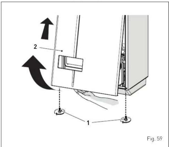
Domestic hot water circuit:
- open the isolation valves of the domestic hot water circuit (if present)
- open one or more than one hot water valve to fill and bleed the domestic hot water circuit
- once bleeding has been completed, close the hot water valves.
Heating circuit:
- open the isolation and air bleeding valves in the highest points of the system
- loosen the automatic bleed valve (3)
- open the isolation valves of the heating circuit (if present)
- Open the filling valve (4)
- Fill until the water overflows from the air bleeding valves and shut off the valves again
- continue filling until the pressure reaches 1-1.2 bar as shown on the pressure gauge (5)
- Close the filling valve (4)
- check that there is no air in the system by bleeding all the radiators and the circuit on the high points of the system
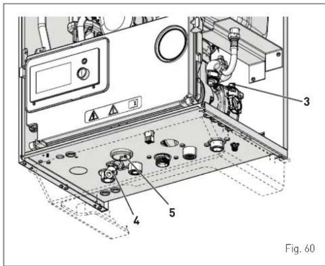
NOTE: to completely remove all air from the system, it is recommended that this operation is repeated a number of times.
- check the pressure on the pressure gauge (5) and if necessary top up until the correct pressure reading appears
- close the automatic bleed valve (3)
- fill the siphon disconnecting it from the pipe or using (by means of) the smoke take-off point.
Refit the front panel of the boiler hooking it on at the top, pushing it forwards and securing it with the screw (1) which was removed previously.
6.16.2 EMPTYING operations
Domestic hot water circuit:
- close the domestic hot water circuit isolation valve (prearranged in installation)
- open one or more than one hot water valve to fill and bleed the domestic hot water circuit.
Boiler:
- loosen the automatic bleed valve (3)
- close the heating circuit isolation valves (prearranged in installation)
- check that the filling valve (4) is shut-off
- connect a rubber hose to the boiler drain valve (6) and open it
- when it has fully emptied, close the drain valve (6)
- close the automatic bleed valve (3).
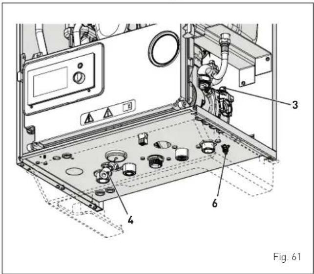
7.1 Preliminary operations

WARNING
- Should it be necessary to access the areas in the bottom part of the appliance, make sure that the system components and pipes are not hot (risk of burning).
- Before replenishing the heating system, put on protective gloves.
Before commissioning the appliance, check that:
– the type of gas is correct for the appliance
- the gas isolation valves for the heating system and the water system are open
- the system pressure as shown on the pressure gauge when the system is cold, is between 1 and 1.2 bar
- the pump impeller rotates freely
- the siphon has been filled
- the flue is fitted correctly.
7.2 Before commissioning
After having carried out the preliminary checks, perform the following to start the boiler:
- set the main system switch to "ON"
- after a few seconds, the "Main screen" is shown
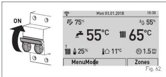
- turn the encoder to select the "Mode" (Mode) function
- press the click encoder to go to the screen to select the "
Function mode" (MODE). Turn the encoder to select the preferred mode e.g. "Winter" (Winter)
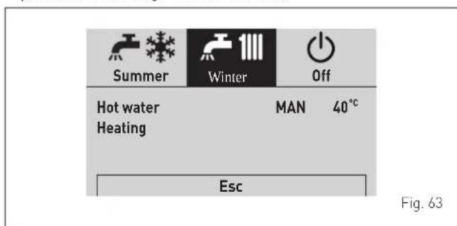
- adjust the air thermostat and check that the boiler starts and operates correctly.
7.3 Main control panel display and settings

CAUTION
We recommend not changing the factory settings so as not to alter optimal appliance operation. For any specific support, please contact the Sime Technical Assistance Service.
7.3.1 Settings using the MODE function
From the "Main screen":
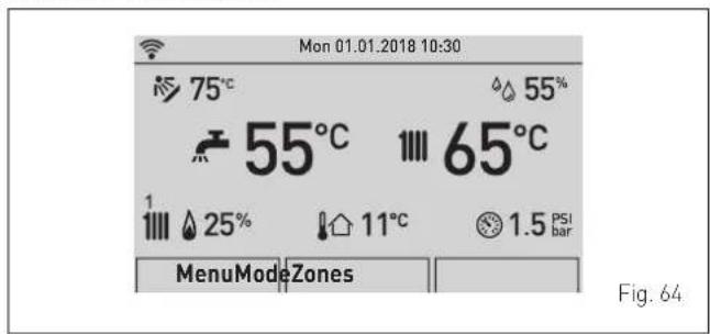
- turn the encoder to select the "Mode" (Mode) function
- press the click encoder to go to the screen to select the "
Function mode" (MODE). Turn the encoder to select the preferred mode e.g. "Winter" (Winter)
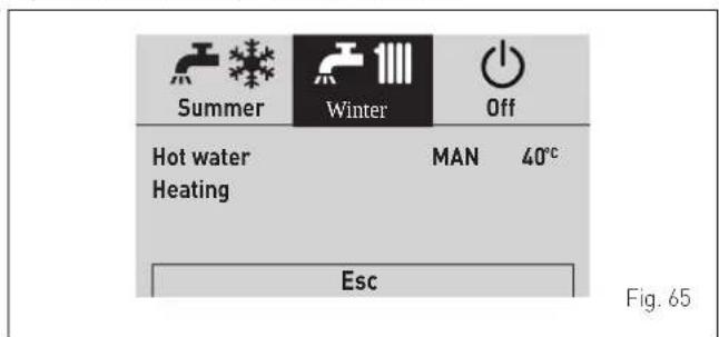
- press the click encoder to confirm the highlighted "Mode" and go to the "rows"
7.3.1.1 Domestic hot water
- turn the encoder to select "Hot water" (DHW)
- press the click encoder to confirm "Hot water" (DHW) and open the submenu
![Summer Winter Off Hot water MAN 40°C Heating Esc Hot water Function Mode MAN Zone heating 45°C Program. Time [...] Fig. 66](/content/2026/05/855257/images/7a674102149d8a8deef89f465359aa13db21074b118f933aeef76197014c62fb.jpg)
- press the click encoder to confirm the highlighted "Row" and access the modifiable area
![Function Mode MAN Hot water setting 45°C Program. Time [...] Fig. 67](/content/2026/05/855257/images/81794e8f06acb80d85e0a1858a333b69eeec996bc6c1b8d5b1089bb050e889e8.jpg)
- turn the encoder to modify the "Data/value" in the permitted field (e.g. OFF - ECO - MAN - AUTO)
- press the click encoder to confirm any modifications made and go back to the row "Function mode" (Function Mode).

CAUTION
For information on boiler time programming, see "Time Programming".
The characteristics of each operating mode available are described below:
| Function mode Description | |
| OFF | DHW (domestic hot water) request NOT active |
| ECO Instantaneous operation (factory setting) | |
| MAN | DHW 3-star function ALWAYS active (with PAR 37 = 1) |
| AUTO_ON | MAN mode operation when the time slot has been activated |
| AUTO_OFF | ECO mode operation when the time slot has been deactivated |
This function is included on boiler models with instantaneous hot water function, with PAR 47 = 1 the function activates when MAN or AUTO mode is set in the ON bands.
Moreover, this function:
- is activated if, during a domestic hot water (DHW) request, the burner turns on for more than 5 seconds
- the function keeps the burner active (at minimum power) at the end of the DHW request, depending on the temperature of the primary heat exchanger
- the function has a maximum duration of 1 hour
- the total execution time is reloaded only if the 3-star function is interrupted by a DHW request
- if the 3-star function is interrupted by a heat request from the heating circuit, or by a request with higher priority, the function will be deactivated.

CAUTION
When the "DHW 3-star" function is activated, it is recommended to set the "Hot water set" to a value below 45^ to prevent excessive temperatures when water starts being drawn.

CAUTION
Setting of the remote control SIME HOME PLUS: to disable the DHW 3-star function (enabling in ECO mode), set the domestic hot water (DHW) function to AUTO mode and disable the MON-SUN period for all time bands.
7.3.1.3 Heating
- turn the encoder to select "Heating" (Heating)
- press the click encoder to confirm "Heating" (Heating) and open the submenu "Zone" (Zones)
![Summer Winter Off Hot water MAN 40 °C Heating Esc Heating Zone 1 [...] Zone 2 [...] Fig. 68](/content/2026/05/855257/images/d088debda9f65f0c54ea52bc07b2cad2867876a982d5371f1d5ce52c9704ebd7.jpg)
- turn the encoder to select the desired zone e.g. Zone 1 (Zone 1) or Zone 2 (Zone 2)
- press the click encoder to confirm the highlighted zone and go to the row
![Zone 1 Information Settings[...] Config [...] Fig. 69](/content/2026/05/855257/images/932ec1160fd4269c2ac0a2485a2f00c5585719795fdbb65bd7cca0cd5866e5cc.jpg)
- Turn the encoder until selecting the desired function, e.g. Settings
![Zone 1 Information [...] Settings [...] Config [...] Fig. 70](/content/2026/05/855257/images/d608cdc588ef4b9d5ce41cb00586b277f8788e5eb4939a2856da3978d2d94e29.jpg)
- press the click encoder to confirm the selected submenu and access the relevant data display
![Room 1 - Settings Function Mode AUTO Set AUTO comfort 20.5°C Set AUTO reduced 17.0°C Set MAN 19.2°C Program. Time [...] Fig. 71](/content/2026/05/855257/images/bf547519c2a74ca6045022c6b62e434d4b0901de55c2451efd486b8825643477.jpg)
- press the click encoder to confirm the highlighted "Row" and access the modifiable area
![Room 1 - Settings Function Mode AUTO Set AUTO comfort 20.5°C Set AUTO reduced 17.0°C Set MAN 19.2°C Program. Time [...]](/content/2026/05/855257/images/f2f193d72cda2637853a73e9e2fa72bc247cff459df250478c3478ff71005c0a.jpg)
Fig. 72
- turn the encoder to modify the "Data/value" in the permitted field (e.g. OFF - ECO - MAN - AUTO)
- press the click encoder to confirm any modifications made and go back to the row "Function mode" (Function Mode).

CAUTION
The settings described above must be done for both zones.

CAUTION
For information on boiler time programming, see "Time Programming".
7.3.2 Fault warnings
If a fault occurs, the screen "Anomaly in progress" (Fault in progress) will appear in place of the "main screen". For the main fault codes, a brief description and suggestions for the user are displayed, based on the seriousness and the frequency with which the fault reappears.
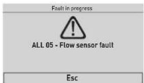
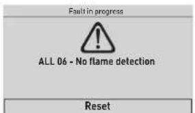
Fig. 73
The fault may be transient (volatile) or it may cause an appliance block.
To restore normal operating conditions:
- if the fault is transient, eliminate the cause of the fault
- if the fault causes a block, eliminate the cause of the fault
and then press the "RESET" (Reset) button; press the encoder to confirm.

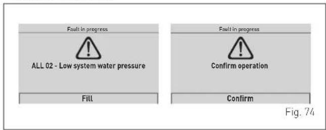
A list of possible faults is given under "Fault / malfunction codes".
7.3.3 Time Programming
The control panel allows up to a maximum of four daily time bands to be managed for the domestic hot water function and the heating function described below. During the programmed time band, the boiler works in COM-FORT heating mode, while outside the programmed time band it works in REDUCED heating mode:
- press the encoder click to confirm "Program.Time" (Program.Time) and go into the modifiable area
![Heating Time Program MondayDay/s 0246 81 01 21 41 61 82 02 22 4 [1] 06:00 - 08:00 [3] [2] 11:00 - 13:00 [4] 18:00 - 23:00 Confirm](/content/2026/05/855257/images/f2ecb1e328d1a4d9cb828abc314dff5be2f00f97616f34cd83cfda0bb9ef9b6c.jpg)
Fig. 75
- turn the encoder to select the "Single days" or the "Group of days"
- press the click encoder to confirm the required selection and access the first "Adjustable time" [1]
![Heating Time Program MondayDay/s [1] 06:00 - 08:00 [3] [2] 11:00 - 13:00 [4] 18:00 - 23:00 Confirm](/content/2026/05/855257/images/03113949e097bffa614908027162efb297871141a746b7ee6936b7ec945b5182.jpg)
Fig. 76
- turn the encoder to modify the "Data/value" on the basis of the required time
- press the click encoder to confirm the modification and move to the next "Data/value"
![Heating Time Program MondayDay/s [1] 06:00 - 08:00 [3] [2] 11:00 - 13:00 [4] 18:00 - 23:00 Confirm](/content/2026/05/855257/images/4e0bf25bf0fa0e9f0bddbcfa3e312f8973776589e976085c8a183f12d1a4c54a.jpg)
Fig. 77
– continue in this way until all the necessary modifications have been made for each day of the week or group of days.
NOTE: The user must work in a CIRCULAR manner, meaning ALWAYS MOVING FORWARDS, even if a mistake is made.

CAUTION
If NO time band is required, set the start and stop times of that band to the same value (e.g. [3] 14:00-14:00).
- When all modifications have been made, turn the encoder to select "Confirm" (Confirm) and press the click encoder to go back to "Single days" or "Groups of days" - press the "ESC" button to go back to the "main screen".
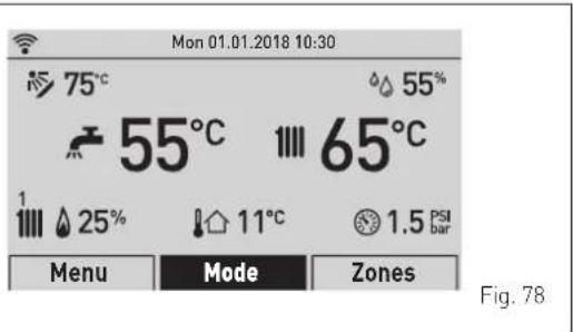
7.3.4 Navigating from the MODE function
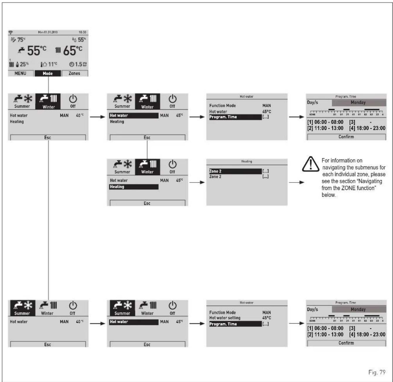
flowchart
graph TD
    A["75°C 55°C 65°C"] --> B["Menu Mode Zones"]
    B --> C["Hot water MAN 40°C"]
    C --> D["Summer Winter Off"]
    D --> E["Hot water MAN 45°C"]
    E --> F["Hot water MAN 45°C"]
    F --> G["Program. Time [..."]]
    G --> H["Day/s Monday"]
    H --> I["[1"] 06:00 - 08:00["3"] -["2"] 11:00 - 13:00["4"] 18:00 - 23:00]
    I --> J["Confirm"]
    C --> K["Esc"]
    K --> L["Summer Winter Off"]
    L --> M["Hot water MAN 45°C"]
    M --> N["Hot water MAN 45°C"]
    N --> O["Energy Transfer"]
    O --> P["Zone 2 [..."] Zone_2["..."]]
    P --> Q["Warning"]
    Q --> R["For information on navigating the submenus for each individual zone, please see the section "Navigating from the ZONE function" below."]
    R --> S["Program. Time"]
    S --> T["Day/s Monday"]
    T --> U["[1"] 06:00 - 08:00["3"] -["2"] 11:00 - 13:00["4"] 18:00 - 23:00]
    T --> V["Confirm"]
7.3.5 Settings under the MENU function
7.3.5.4 GENERAL SETTINGS menu
From the "main screen", proceed as follows:
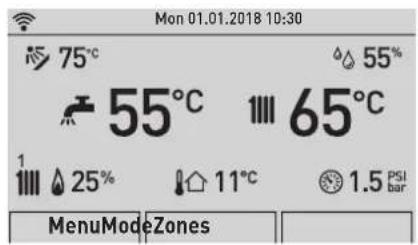
Fig. 80

- turn the "encoder and modify the "data/value" in the field allowed (e.g. from ENG to ITA)
![GENERAL SETTINGS Language EN Date and time [...] Display [...] Factory settings [...]](/content/2026/05/855257/images/b16694c0335976cd98dad7ed4dc1baac184bc24e590fb8bd898e8574f5d074db.jpg)
Fig. 84

- turn the encoder to select the "Menu" (Menu) function
and press the click encoder to enter the "Menu" (Menu) selection screen
- turn the encoder to select the "General settings" (GENERAL SETTINGS) menu
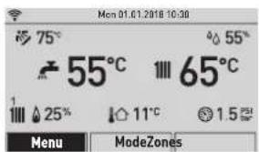
![GENERAL SETTINGS INFORMATION[...] TECHNICAL[...]](/content/2026/05/855257/images/8b5cebb1445616c0f53990bdf23c0a58cbd32b65e8be88c5dc8d88117828e924.jpg)
Fig. 81

- press the click encoder to confirm the modification and go back to the submenu
![GENERAL SETTINGS Language EN Date and time [...] Display [...] Factory settings [...]](/content/2026/05/855257/images/b564d90b8b34213b3fa49ef628acde1b7b3aa4affa26294796db9c4e21c5f457.jpg)
Fig. 85

- turn the encoder to select another submenu (e.g. date and time (Date and time))
![GENERAL SETTINGS Language EN Date and time [...] Display [...] Factory settings [...]](/content/2026/05/855257/images/d0f82c9ffadd234b5524ca5ec6cc4e00a01b07b810f8435c384597e3fba91951.jpg)
Fig. 86

- press the click encoder to confirm the highlighted menu and access the submenus
![GENERAL SETTINGS Language ITA Date and time [...] Display [...] Factory settings [...]](/content/2026/05/855257/images/54e3083687bad81e8d91f6bd011be9d7d80eee78e8e2b66a9d7d8aca0d1e6061.jpg)
Fig. 82

- press the click encoder to confirm the highlighted submenu and access the modifiable area
- the first modifiable "Data/value" is highlighted (e.g. 01)
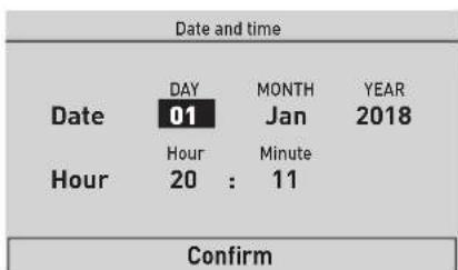
Fig. 87

- press the click encoder to confirm the highlighted submenu and select the modifiable area
![GENERAL SETTINGS Language ITA Date and time [...] Display [...] Factory settings [...]](/content/2026/05/855257/images/b66e6a709d8f79f3b018f412cc1fc48a1f57181906c9b9d6dfb2094f9d4a0427.jpg)
Fig. 83
the first modifiable "Data/value" is highlighted (e.g. 06)
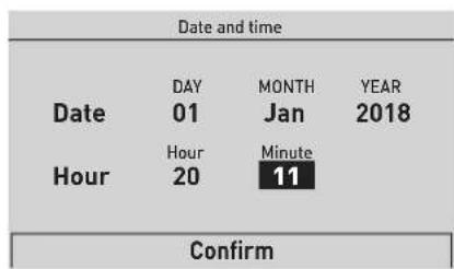
Fig. 88

- press the click encoder to confirm the modification and select the next "Data/value" which will be highlighted (e.g. 01)
- continue in this way until all the necessary modifications have been made
- after all modifications have been made, use the encoder to select "Confirm" and press the click encoder to go back to the initial submenu (Date and time).
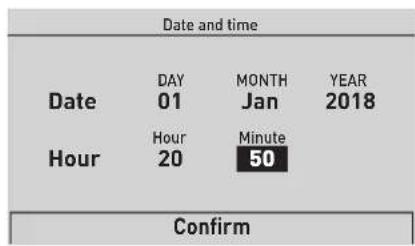
Fig. 89

- press the click encoder to confirm the modification and select the next "Data/value" which will be highlighted (e.g. 01)
- continue in this way until all the necessary modifications have been made
- after all modifications have been made, use the encoder to select "Confirm" and press the click encoder to go back to the initial submenu (Date and time).
NOTE: The user must work in a CIRCULAR manner, meaning ALWAYS MOVING FORWARDS, even if a mistake is made.

- turn the encoder to select another Menu e.g. "Display" (Display).
The "Display" menu allows the user to adjust:
- display contrast
- duration of the display back-lighting
The operating procedure is as has been described so far.
![GENERAL SETTINGS Language EN Date and time [...] Display Factory settings [...]](/content/2026/05/855257/images/ec87ba115342c94cf8a4d3df31f5ccb93f0ba4c6e7d45ee70240d2c6c6cc93cd.jpg)
Fig. 90

CAUTION
"Factory settings" submenu
It is recommended that the user access this submenu ONLY to restore the "Factory settings" (Factory settings), thereby deleting all settings made by the user.
To proceed:
- press the click encoder to access the modifiable area. A screen appears offering the following options:
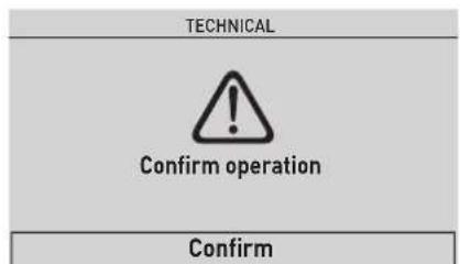
Fig. 91
- press the encoder to select "Confirm" and press the click encoder to restore the "Factory settings". After a few seconds, go back to the "main screen".
7.3.5.5 INFORMATION menu
The INFORMATION menu is read-only and the data cannot be modified.
From the "Main screen":
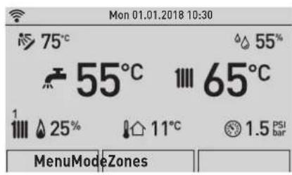
Fig. 92
- turn the encoder to select the "Menu" (Menu) function
and press the click encoder to enter the "Menu" (Menu) selection screen - turn the encoder to select the "INFORMATION" (Information) menu
![Menu GENERAL SETTINGS [...] INFORMATION TECHNICAL [...]](/content/2026/05/855257/images/5651e93c3e737c4f36ff2efeba2555bffb43297c565daa132a72e7e56bc79baf.jpg)
Fig. 93
- press the click encoder to confirm "INFORMATION" (INFORMATION) and enter the submenus
![Information Boiler DHW [...] Version SCP 1.00 Version MB 1.00 Version BC 1.00](/content/2026/05/855257/images/61c240b62a18f69a5a5beb1c909f25ff715cab870dda04d72dd19bd0c6cf7a99.jpg)
Fig. 94
- turn the encoder to select the required submenu
- press the click encoder to confirm the selected submenu and access the relevant data display
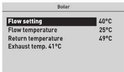
Fig. 95
- select "Back" (Back) and press the click encoder to return to the submenus
- turn the encoder to select another submenu
![Information Boiler [...] DHW Version SCP 1.00 Version MB 1.00 Version BC 1.00](/content/2026/05/855257/images/8de3f6b35f7161ea586cd459defaf2ae09c630a22fb789e69264546af5f1467b.jpg)
Fig. 96
- press the click encoder to confirm the selected submenu and access the relevant data display
- continue in this way until all the necessary information has been shown
- press the "ESC" button to go back to the "main screen".
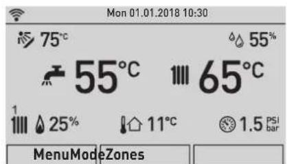
Fig. 97
7.3.5.6 TECHNICAL menu
It is recommended that the TECHNICAL Menu only be used by professionally qualified technicians, since it is used to modify system management data.

CAUTION
We recommend not changing the factory settings so as not to alter optimal appliance operation. For any specific support, please contact the Sime Technical Assistance Service.
From the "Main screen":
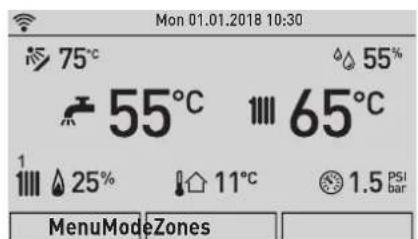
Fig. 98
- turn the encoder to select the "Menu" (Menu) function and press the click encoder to enter the "Menu" (Menu) selection screen
- turn the encoder to select the "TECHNICAL"(Technical) menu
![Mon 01.01.2018 10:30 75° 55° 55°C 65°C 1 25° 11°C 1.5 Menu Mode Zones Menu GENERAL SETTINGS [...] INFORMATION [...] TECHNICAL Fig. 99](/content/2026/05/855257/images/1e1c0c5dc1df80a1fded949d8c65a5060daa90c44a9243ae1f5a17c43932f106.jpg)
To proceed:
- press the click encoder to access the modifiable area. The following screen is displayed:
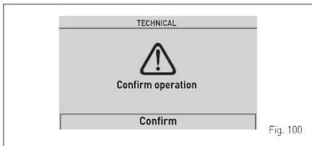
- turn the encoder to select "Confirm" (Confirm) and press the click encoder to open the submenus
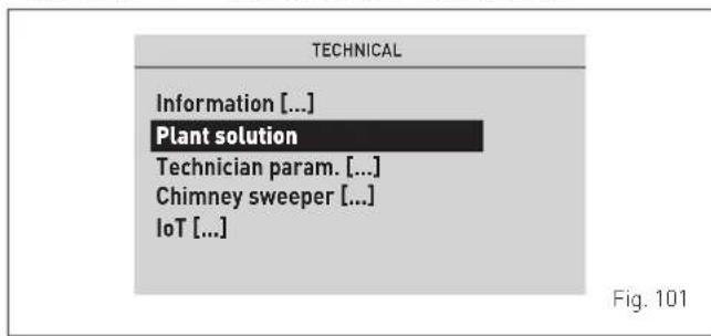
- turn the encoder to select the desired submenu, e.g. "Plant solution" (Plant solution) - press the click encoder to confirm the selected submenu and enter the modifiable data area
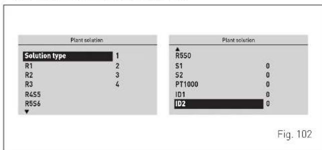
bar
| Solution type | Value | | :--- | :--- | | R1 | 1 | | R2 | 2 | | R3 | 3 | | R455 | 4 | | R556 | | | | | | | | | | | | | | | | | | | | | | | | | | | | | | | | | | | | | | | | | | | | | | | | | | | | | R550 | | | S1 | 0 | | S2 | 0 | | PT1000 | 0 | | ID1 | 0 | | ID2 | 0 |- press the click encoder to confirm the highlighted "Row" and access the modifiable area
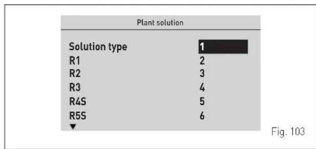
bar
Plant solution | Solution type | Value | | :--- | :--- | | R1 | 2 | | R2 | 3 | | R3 | 4 | | R4S | 5 | | R5S | 6 | Fig. 103- press the encoder to set the new value - press the click encoder to confirm the change and move to the another row
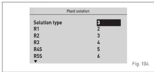
bar
Plant solution | Solution type | Value | | :--- | :--- | | R1 | 2 | | R2 | 3 | | R3 | 4 | | R4S | 5 | | R5S | 6 | Fig. 104- after displaying/making changes, press the "ESC" button to complete the modification and return to the main screens.
7.3.6 Navigating from the MENU function
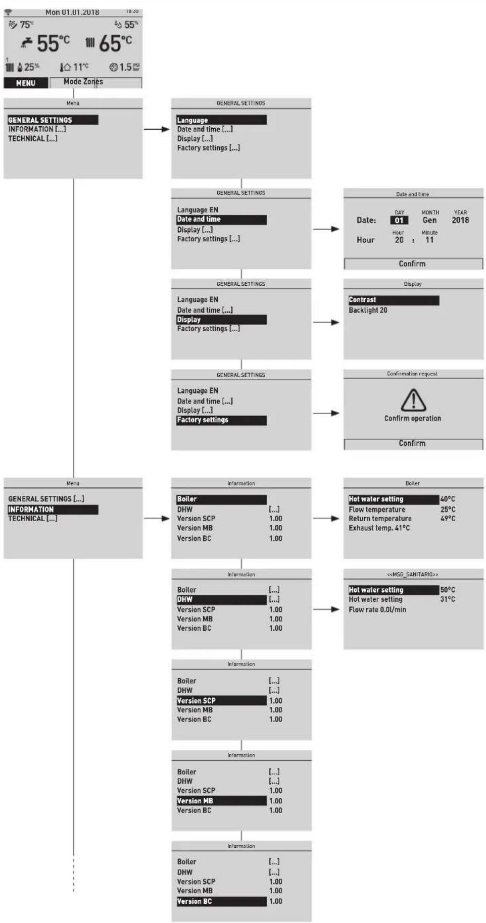
flowchart
graph TD
    A["Menu Mode Zones"] --> B["General Settings"]
    B --> C["Language"]
    C --> D["Date and time [..."]]
    C --> E["Display [..."]]
    C --> F["Factory settings [..."]]
    B --> G["General Settings"]
    G --> H["Language EN"]
    H --> I["Date and time [..."]]
    H --> J["Display [..."]]
    H --> K["Factory settings [..."]]
    G --> L["General Settings"]
    L --> M["Language EN"]
    M --> N["Date and time [..."]]
    M --> O["Display"]
    M --> P["Factory settings [..."]]
    L --> Q["General Settings"]
    Q --> R["Language EN"]
    R --> S["Date and time [..."]]
    R --> T["Display [..."]]
    R --> U["Factory settings"]
    Q --> V["Information"]
    V --> W["Boiler"]
    W --> X["DHW [..."]]
    W --> Y["Version SCP 1.00"]
    W --> Z["Version MB 1.00"]
    W --> AA["Version BC 1.00"]
    V --> AB["Information"]
    AB --> AC["Boiler [..."]]
    AB --> AD["DHW [..."]]
    AB --> AE["Version SCP 1.00"]
    AB --> AF["Version MB 1.00"]
    AB --> AG["Version BC 1.00"]
    AB --> AH["Information"]
    AH --> AI["Boiler [..."]]
    AH --> AJ["DHW [..."]]
    AH --> AK["Version SCP 1.00"]
    AH --> AL["Version MB 1.00"]
    AH --> AM["Version BC 1.00"]
    A --> AN["Date and time"]
    AN --> AO["Day MONTH YEAR"]
    AN --> AP["Date: 01 Gen 2018"]
    AN --> AQ["Hour 20 : 11"]
    AN --> AR["Confirm"]
    AN --> AS["Contrast Backlight 20"]
    AN --> AT["Confirmation request"]
    AT --> AU["Warning icon"]
    AT --> AV["Confirm operation"]
    AT --> AW["Confirm"]

    B --> AC["General Settings Information"]

    C --> AC
    G --> AC
    L --> AC
    Q --> AC
    R --> AC
    V --> AC
    W --> AC
    AB --> AC
    AC --> AD
    AD --> AE
    AE --> AF
    AF --> AG
Fig. 105
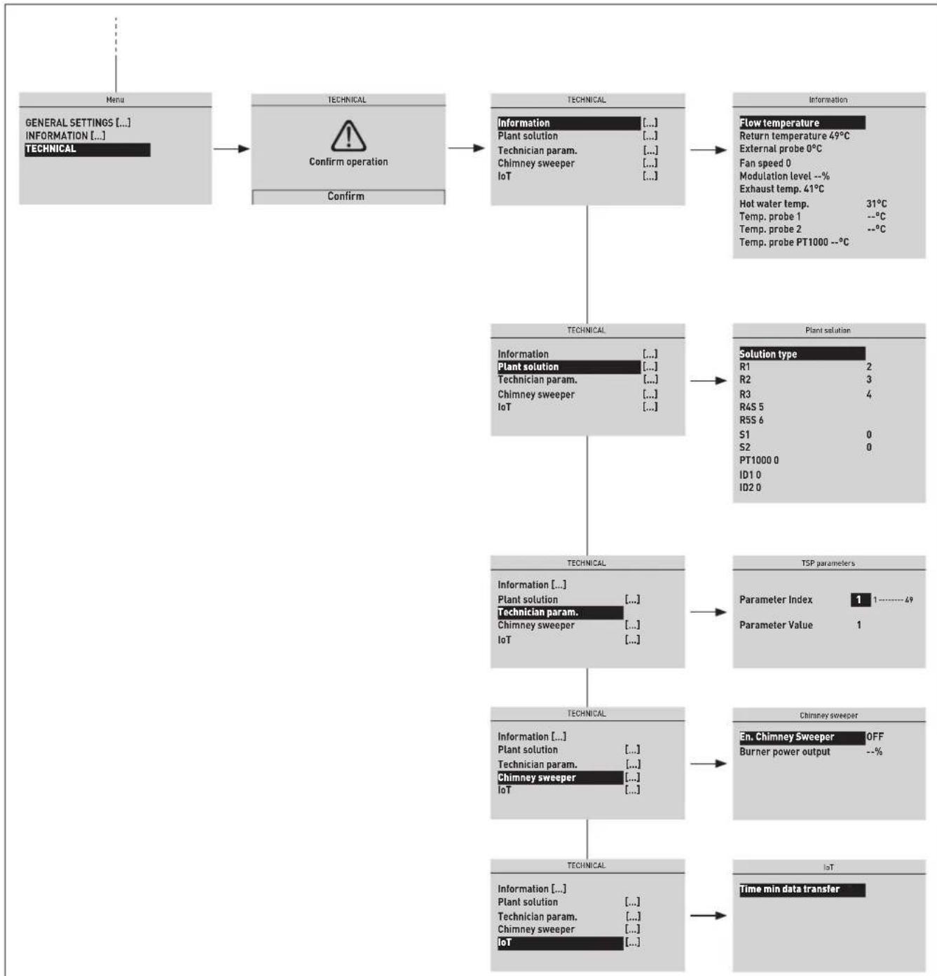
flowchart
graph TD
    A["Menu"] --> B["GENERAL SETTINGS [..."] INFORMATION["..."] TECHNICAL]
    B --> C["TECHNICAL"]
    C --> D["CONFIRM OPERATION"]
    D --> E["TECHNICAL"]
    E --> F["Information [..."]]
    F --> G["Plant solution [..."]]
    G --> H["Technician param. [..."]]
    H --> I["Chimney sweeper [..."]]
    I --> J["IoT [..."]]
    J --> K["TECHNICAL"]
    K --> L["Information [..."]]
    L --> M["Plant solution [..."]]
    M --> N["Technician param. [..."]]
    N --> O["Chimney sweeper [..."]]
    O --> P["IoT [..."]]
    P --> Q["TECHNICAL"]
    Q --> R["Information [..."]]
    R --> S["Plant solution [..."]]
    S --> T["Technician param. [..."]]
    T --> U["Chimney sweeper [..."]]
    U --> V["IoT [..."]]
    V --> W["TECHNICAL"]
    W --> X["Information [..."]]
    X --> Y["Plant solution [..."]]
    Y --> Z["Technician param. [..."]]
    Z --> AA["Chimney sweeper [..."]]
    AA --> AB["IoT [..."]]
    AB --> AC["Time min data transfer"]
Fig. 106
7.3.7 Settings under the ZONE function
7.3.7.7 INFORMATION menu
The INFORMATION menu is read-only and the data cannot be modified.
From the "Main screen":
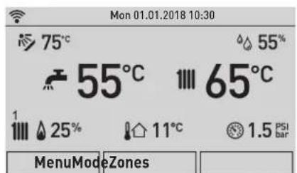
Fig. 107
- turn the encoder to select the "Zone" (Zones) function
- press the click encoder to go to the screen to select the "Zone" (Zones)
![Zones Zone 1 Zone 2 [...] Zone 3 [...] Zone 4 [...]](/content/2026/05/855257/images/6ac4a03ae2535cad6c89fdcb3f239a48d7cf4e8ce0c3de110c8c63e062f09328.jpg)
Fig. 108
- turn the encoder to select the desired zone e.g. "Zone 1" (Zone 1)
- press the click encoder to confirm the highlighted zone and go to the row
- turn the encoder to select the "INFORMATION" (INFORMATION) menu
![Zone 1 Information Settings[...] Config[...]](/content/2026/05/855257/images/68c456320d87a631b25084fc108792c15b7904d8c6d5220c68ba636e68270798.jpg)
Fig. 109
- press the click encoder to confirm "Information" (INFORMATION) and enter the display area for the relevant data
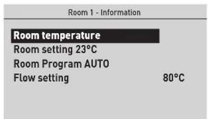
Fig. 110
- press the "ESC" button to go back to the "main screen".
7.3.7.8 SETTINGS menu
From the "Main screen":
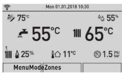
Fig. 111
- turn the encoder to select the "Zone" (Zones) function
- press the click encoder to go to the screen to select the "Zone" (Zones)
![Zones Zone 1 Zone 2 [...] Zone 3 [...] Zone 4 [...]](/content/2026/05/855257/images/cce04ac3f1d9eac2724846f13d95fb6df2017d49a6986e0b6ec7f72513a7244d.jpg)
Fig. 112
- turn the encoder to select the desired zone e.g. "Zone 1" (Zone 1)
- press the click encoder to confirm the highlighted zone and go to the row
- turn the encoder (○) to select the "Settings" menu (Settings)
![Zone 1 Information [...] Settings [...] Config[...]](/content/2026/05/855257/images/0530663c1f5a57b4fb9f9a6987d726c37631c05fdd4397f63959a3c91df58526.jpg)
Fig. 113
- press the click encoder to confirm the selected submenu and access the relevant data display
![Room 1 - Settings Function Mode AUTO Set AUTO comfort 20.5°C Set AUTO reduced 17.0°C Set MAN 19.2°C Program. Time [...]](/content/2026/05/855257/images/da9e1301a860fa11140b7eb815f818895ccba745def0b34c82d62ac937288b63.jpg)
Fig. 114
- press the click encoder to confirm the highlighted "Row" and access the modifiable area
![Room 1 - Settings Function Mode AUTO Set AUTO comfort 20.5°C Set AUTO reduced 17.0°C Set MAN 19.2°C Program. Time [...]](/content/2026/05/855257/images/3db18f891cb23604808a0e3780d25b02cf875a70c893cc1ea3fd51a373df7d90.jpg)
Fig. 115
- turn the encoder to modify the "Data/value" in the permitted field (e.g. OFF - ECO - MAN - AUTO)
- press the click encoder to confirm any modifications made and go back to the row "Function mode" (Function Mode).

CAUTION
The settings described above must be done for all zones.
7.3.7.9 CONFIGURATION menu
From the "Main screen":
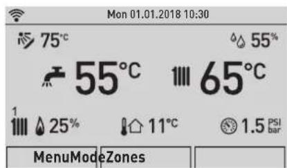
Fig. 116
- turn the encoder to select the "Zone" (Zones) function
- press the click encoder to go to the screen to select the "Zone" (Zones)
![Zones Zone 1 Zone 2 [...] Zone 3 [...] Zone 4 [...]](/content/2026/05/855257/images/c706fa651267ead02def288410fb5e37c4d29669328df9e4bdb63117e49711f6.jpg)
Fig. 117
- turn the encoder to select the desired zone e.g. "Zone 1" (Zone 1)
- press the click encoder to confirm the highlighted zone and go to the row
- turn the encoder to select the "Configuration" (Config) menu
![Zone 1 Information[...] Settings[...] Config Fig. 118](/content/2026/05/855257/images/2f94ef389462db1874fafaf24aaac18ec7e5ad718a454bd5fdb4b543b0fbf683.jpg)
- press the click encoder to confirm the selected submenu and access the relevant data display
![Room 1 - Config Regulation [...] Room probe [...] Water circuit [...] Fig. 119](/content/2026/05/855257/images/97167fe61c2ce20477e2d9fb335321d158a676295e6ecd900589fb0a72e44471.jpg)
- turn the encoder to select the required submenu - press the click encoder to confirm the selected submenu and access the relevant data display
![Room 1 - Room probe Type OT Address M3 0 Input 0 Status -- Connect [...] Fig. 120](/content/2026/05/855257/images/80d0a670b59090335f194e45087987689e4ea4b0c97c6c4ff25ab9f007007356.jpg)
- press the click encoder to confirm the highlighted "Row" and access the modifiable area
![Room 1 - Room probe Type OT Address M3 0 Input 0 Status -- Connect [...] Fig. 121](/content/2026/05/855257/images/bf62628b47a69f477743c76961a6b1ab777beacc9a392c5653ceaf6263c9780b.jpg)
- turn the encoder to modify the "data/value" in the permitted field (e.g. OFF - OT - TA - RF - M3) - press the click encoder to confirm any changes made and go back to the highlighted "Row".
The full list of configuration parameters can be found in the tables below.
Room sensor parameters
| Parameter Description | |
| Motor type | OFF = No zone room sensor present |
| OT = Zone controlled directly via remote control (OT) | |
| TA = Zone managed directly by room thermostat (TA) connected in the boiler | |
| RF = Zone managed directly by wireless sensor (RF) | |
| M3 = Zone manage by wired sensor on M3 bus | |
| M3 address | [0 ... 3 (Default = 0)] = Address for device connected to bus M3, holding the input sensor, whether M3 or RF installed on an RF concentrator. This address is usually set via the dipswitch on the device itself |
| Input | [1 ... 8 (Default = 1)] = Input number for the RF concentrator (sometimes virtual, as for RF) to which a sensor or generic input will be associated |
| Status | -- = Status awaiting verification |
| OK = Installation complete / sensor present | |
| ... = Being installed (waiting for RF sensor on selected RF concentrator) | |
| ERR = Installation or configuration error | |
Water circuit parameters (hydraulic)
| Parameter Description | |
| Motor type | OFF = Zone and circuit not present or not controlled |
| CALD = Circuits integrated in the boiler (fixed: Circuit 1 for Zone 1 and Circuit 2 for Zone 2) | |
| ATT = Circuits managed by actuator on bus M3 (see kit code 8092272 - Multi-zone board M3) | |
| M3 address | [0 ... 3 (Default = 0)] = Address for device connected to bus M3, actuator M3, holding the output relay, whether single or multiple (Mix), on an actuator. This address is usually set via the dipswitch on the device itself |
| Output | [1 ... 4 (Default = 1)] = This is the physical output number (e.g. single or multiple relay) of the actuator M3 to which the hydraulic circuit for the selected zone will be associated. |
| Category | DIR = Direct circuit (high temperature) |
| MIX = Mixed circuit (low temperature) | |
| Status | -- = Status awaiting verification |
| OK = Installation complete / sensor present | |
| ... = Being installed (waiting for RF sensor on selected RF concentrator) | |
| ERR = Installation or configuration error | |

CAUTION
The settings described above must be done for all zones.
7.3.8 Navigating from the ZONE function
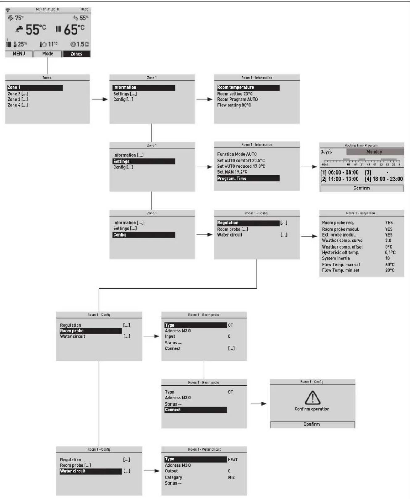
flowchart
graph TD
    A["75°C 55°C 65°C"] --> B["Menu Mode Zones"]
    B --> C["Zones Zone 1"]
    C --> D["Zone 1 Information Settings [... Config ..."]
    D --> E["Room 1 - Information Room temperature Room setting 23°C Room Program AUTO Flow setting 80°C"]
    E --> F["Zone 1 Information [... Settings Config ..."]
    F --> G["Room 1 - Information Function Mode AUTO Set AUTO comfort 20.5°C Set AUTO reduced 17.0°C Set MAN 19.2°C Program Time"]
    G --> H["Day/s Heating Time Program: [1"] 06:00 - 08:00["3"] -["2"] 11:00 - 13:00["4"] 18:00 - 23:00 Confirm]
    H --> I["Room 1 - Configuration Regulation Room probe ... Water circuit ..."]
    I --> J["Room 1 - Regulation Room probe req. YES Room probe modul. YES Ext. probe modut. YES Weather comp. curve 3.0 Weather comp. offset 0°C Hysterlisis off temp. 0,1°C System Inertia 10 Flow Temp. max set 60°C Flow Temp. min set 20°C"]
    J --> K["Room 1 - Control Type Address M3 0 Input Status -- Connect OT"]
    K --> L["Room 1 - Room probe Type Address M3 0 Status -- Connect OT"]
    L --> M["Room 1 - Config Type Address M3 0 Output Category Mix"]
    M --> N["Room 1 - Water circuit Type Heat Address M3 0 Output Category Mix"]
Fig. 122
7.4 Parameter setting and display
To access the parameters menu from the "Main screen":
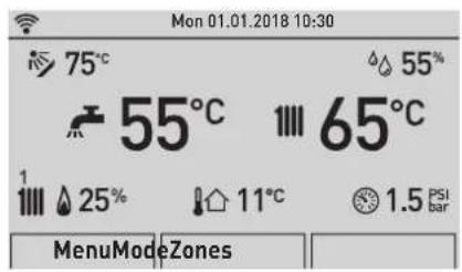
Fig. 123
- turn the encoder to select the "Menu" (Menu) function and press the click encoder to enter the "Menu" (Menu) selection screen
- turn the encoder to select the "TECHNICAL"(Technical) menu
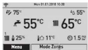
![Menu GENERAL SETTINGS [...] INFORMATION [...] TECHNICAL](/content/2026/05/855257/images/241e0c1b007690dc8d882446bcbd618b9782920cb91269eb50c9fbfec2569f97.jpg)
Fig. 124
To proceed:
- press the click encoder to access the modifiable area. The following screen is displayed:
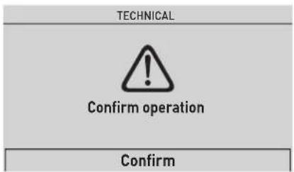
Fig. 125
- turn the encoder to select "Confirm" (Confirm) and press the click encoder to open the submenus
- turn the encoder to select "Technician param." (Technician param.) item and press the click encoder to enter the boiler "Parameter settings" area
![TECHNICAL Information [...] Plant solution [...] Technician param. Chimney sweeper [...] IoT [...]](/content/2026/05/855257/images/68d9ccdc3e7eb2f1883de744300f974a31dc3cda092065a1fd10bd8b789be0ff.jpg)
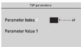
Fig. 126
- where the "Parameter index" (Parameter Index:) refers to the table found in section "List of parameters"
- Turn the encoder to scroll through the list of parameters and check the value
If the value of the selected parameter is to be modified:
- press the click encoder to access the value modification area
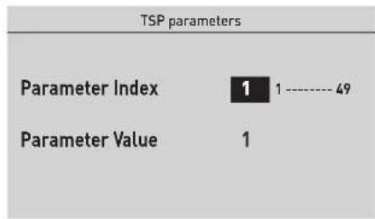
Fig. 127
- press the encoder to set the new value
- press the click encoder to confirm the modification and move on to another parameter
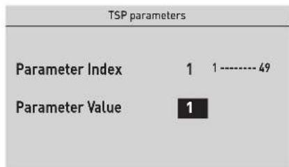
Fig. 128
- after displaying/making changes, press the "ESC" button to complete the modification and return to the "main screen".
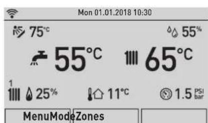
Fig. 129
7.5 List of parameters
Parameter PAR 01 is factory set according to the table "A" below and automatically generates the settings for parameters PAR 05 and PAR 09.

IT IS FORBIDDEN
Use settings other than those shown in table "A" as this could generate a serious boiler malfunction.
TABLE "A"
| PAR. NO. | Type of gas METHANE LPG G20 - I2E | |||||||||
| Boiler power (kW) | 25 30 | 35 25 30 | 35 25 30 35 | |||||||
| 01 | Index showing boiler power in kW and type of boiler | 2 | 3 | 4 | 6 | 7 | 8 | 10 | 11 | 12 |
| PAR. NO. | Description Range U/M Step Default | ||||
| 02 | Hydraulic configuration and system type | See the "System solutions" section | - | - | 1 |
| 04 System connected to circuit 1 | 0 = high temperature1 = low temperature | - | - | 0 | |
| 05 Water pressure switch TSP | 0 = water pressure switch1 = water pressure transducer (only pressure displayed)2 = transducer 0-4 bar | - | - | 2 | |
| 06 | External sensor value correction | -5 .. +5 | °C | 1 | 5 |
| 07 | Boiler and AUX anti-freeze threshold | 0 .. +10 | °C | 1 | 3 |
| 08 | External Sensor Antifreeze Threshold-- = Disabled | -9 .. +5 .. [15 = disabled] | °C | 1 | 7 |
| 09 | Ignition fan speed | 80 .. 160 | RPMx25 | 1 | 128 |
| 10 | Select heat pump or boiler switchover | -20 .. 30 | °C -20 | 1 | 25 |
| 11 | Boiler activation delay after heat pump activation | 1 .. 60 | Min | 1 | 20 |
| 12 | Minimum Heating Temperature Adjustment Zone 1 | 20 .. PAR 13 | °C | 1 | 20 |
| 13 | Maximum Heating Temperature Adjustment Zone 1 | PAR 12 .. 80 | °C | 1 | 70 |
| 14 | Zone 1 heating climatic curve K | 3 .. 40 | - | 1 | 20 |
| 15 | Minimum Heating Temperature Adjustment Zone 2 | 20 .. PAR 16 | °C | 1 | 20 |
| 16 | Maximum Heating Temperature Adjustment Zone 2 | PAR 15 .. 80 | °C | 1 | 80 |
| 17 | Zone 2 heating climatic curve K | 3 .. 40 | - | 1 | 20 |
| 18 Heating Curve Incline | 0 .. 200 | TSP x 10.2 secs | 1 | 100 | |
| 19 | Heating maximum Output (user) | 0 .. 100 | % | 1 | 100 |
| 20 | Minimum power heating/domestic hot water (premixed) | 0 .. 100 | % | 1 | 0 |
| 21 Heating Post-Circulation Time | 0 .. 99 | TSP x 10 secs | 1 | 3 | |
| 22 | Heating Pump Activation Delay | 0 .. 60 | sec. | 1 | 0 |
| 23 | Activation delay (AFCT) | 0 .. 60 | Min | 1 | 3 |
| 24 | Maximum domestic hot water temperature | 35 .. 67 | °C | 1 | 60 |
| 25 | Maximum power domestic hot water | 0 .. 100 | % | 1 | 100 |
| 26 Configuring the DHW | 0 = rapid1 = hot water tank with thermostat2 = hot water tank with sensor | - | - | - | |
| 27 | DHW activation delay with solar power | 0 .. 30 | sec. | 1 | 0 |
| 28 | Anti-legionella Function (Only hot water tank)-- = Disabled | 50 .. 80 | °C | 1 | 49 |
| 29 Domestic Hot Water Modulation with Flow meter | 0 = Disabled1 = Enabled | - | - | 0 | |
| 30 Relay 1 function | 0 = not used1 = solar pump2 = direct zone 13 = N.O. boiler ON/OFF status output4 = N.C. boiler ON/OFF status output5 = N.O. alarm output6 = N.C. alarm output7 = direct zone 28 = mix valve [position A]9 = mix valve [position B]10 = remote ignition transformer11 = mix zone pump for hybrid kit12 = supplementary source - heat pump13 = supplementary source - pellet boiler14 = supplementary source - fireplace or heat pump with photovoltaic consent15 = semi-automatic filling16 = DHW recirculation pump17 = command18 = function | -- 0 | |||
| 31 Relay 2 function | 0 = not used1 = solar pump2 = direct zone 13 = N.O. boiler ON/OFF status output4 = N.C. boiler ON/OFF status output5 = N.O. alarm output6 = N.C. alarm output7 = direct zone 28 = mix valve [position A]9 = mix valve [position B]10 = remote ignition transformer11 = mix zone pump for hybrid kit12 = supplementary source - heat pump14 = supplementary source - pellet boiler15 = semi-automatic filling16 = DHW recirculation pump17 = command18 = function | -- 0 | |||
| 32 Relay 3 function | 0 = not used1 = solar pump2 = direct zone 13 = N.O. boiler ON/OFF status output4 = N.C. boiler ON/OFF status output5 = N.O. alarm output6 = N.C. alarm output7 = direct zone 28 = mix valve [position A]9 = mix valve [position B]10 = remote ignition transformer11 = mix zone pump for hybrid kit12 = supplementary source - heat pump15 = semi-automatic filling16 = DHW recirculation pump17 = command18 = function | -- 0 | |||
| 33 Relay 4 function | 0 = not used1 = solar pump2 = direct zone 13 = N.O. boiler ON/OFF status output4 = N.C. boiler ON/OFF status output5 = N.O. alarm output6 = N.C. alarm output7 = direct zone 28 = mix valve [position A]9 = mix valve [position B]10 = not used11 = mix zone pump for hybrid kit12 = supplementary source - heat pump13 = supplementary source - pellet boiler14 = supplementary source - fireplace or heat pump with photovoltaic consent15 = semi-automatic filling16 = DHW recirculation pump17 = command18 = function | -- 0 | |||
| 34 Relay 5 function | 0 = not used1 = solar pump2 = direct zone 13 = N.O. boiler ON/OFF status output4 = N.C. boiler ON/OFF status output5 = N.O. alarm output6 = N.C. alarm output7 = direct zone 28 = mix valve (position A)9 = mix valve (position B)10 = not used11 = mix zone pump for hybrid kit12 = supplementary source - heat pump13 = supplementary source - pellet boiler14 = supplementary source - fireplace or heat pump with photovoltaic consent15 = semi-automatic filling16 = DHW recirculation pump17 = command18 = function | -- 0 | |||
| 35 Use of 0-10V input | 0 = no1 = remote boiler power | -- 0 | |||
| 36 Configuring SC input (PT1000) | 0 = not used1 = solar sensor2 = system safety thermostat | -- 0 | |||
| 37 Configuring input SAUX 2 | 0 = not used1 = system delivery sensor2 = preheated DHW inlet sensor3 = solar hot water tank sensor4 = mix zone sensor5 = delivery probe after hydraulic compensator | -- 0 | |||
| 38 Configuring input SAUX 2 | 0 = not used1 = system delivery sensor2 = preheated DHW inlet sensor3 = solar hot water tank sensor4 = mix zone sensor5 = delivery probe after hydraulic compensator | -- 0 | |||
| 39 Configuring digital input 1 | 0 = not used1 = remote ignition2 = external event boiler off (positive pol.)3 = external event boiler off (negative pol.)4 = DHW programmable timer5 = CH programmable timer6 = alternative source readiness (fireplace only)7 = system safety thermostat TSI (for low temperatures) | -- 0 | |||
| 40 Configuring digital input 2 | 0 = not used1 = remote ignition2 = external event boiler off (positive pol.)3 = external event boiler off (negative pol.)4 = DHW programmable timer5 = CH programmable timer6 = alternative source readiness (fireplace only)7 = system safety thermostat TSI (for low temperatures) | -- 0 | |||
| 41 Modulating pump operating minimum 20 .. 100 -- 30 | |||||
| 42 Modulating pump operating mode | 0 = fixed speed1 = modulating according to ΔT | -- 1 | |||
| 43 | ΔT Modulating pump delivery/Return | 10 .. 40 | °C | 1 | 20 |
| 44 Boiler pump always ON in winter | 0 = Disabled1 = Enabled | -- 0 | |||
| 45 Enabling preheating | 0 = Disabled1 = Enabled | -- 0 | |||
| 46 Enabling solar function | 0 = Disabled1 = Enabled | -- 0 | |||
| 47 Activation of DHW 3-star function | 0 = Disabled1 = Enabled | -- 0 | |||
| 48 INST Parameter set to default 0 .. 1 -- 0 | |||||
| 49 | Access to OEM menu | - | - | 0 | |
7.6 Fault / malfunction codes
If a fault occurs, the screen "Anomaly in progress" (FAULT IN PROGRESS) will appear in place of the "main screen". For the main fault codes, a brief description and suggestions for the user are displayed, based on the seriousness and the frequency with which the fault reappears.
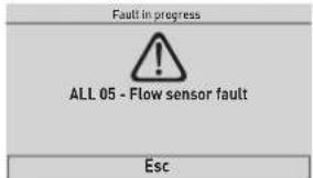
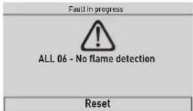
Fig. 130
The fault may be transient (volatile) or it may cause an appliance block.
To restore normal operating conditions:
- if the fault is transient, eliminate the cause of the fault
- if the fault causes a block, eliminate the cause of the fault
and then press the "RESET" (Reset) button; press the encoder to confirm.

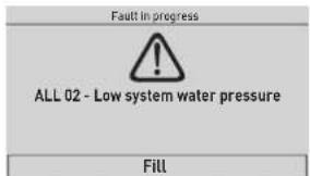
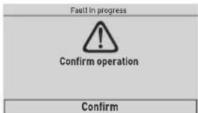
Fig. 131
| Type No. | Description |
| ALL 2 | Low water pressure in system |
| ALL 3 | High water pressure in system |
| ALL 4 | |
| ALL 5 | Delivery sensor fault |
| ALL 6 | No flame detection |
| ALL 7 | Sensor or safety thermostat intervenes |
| ALL 8 | Fault in the flame detection circuit |
| ALL 9 | No water circulating in the system |
| ALL 10 | Auxiliary sensor 1 fault |
| ALL 12 | Domestic hot water sensor fault in tank mode |
| ALL 13 | Smoke probe intervention |
| ALL 14 | Smoke probe fault |
| ALL 15 | Fan fault |
| ALL 19 | External sensor fault |
| ALL 20 |
| Type | No. | Description |
| ALL 30 | Return sensor fault (boiler sensor fault for T models) | |
| ALL 31 | PT1000 sensor fault | |
| ALL 32 | Auxiliary sensor 2 fault | |
| ALL 37 | Fault due to low network voltage | |
| ALL 40 | Incorrect network frequency detected | |
| ALL 41 | Flame loss more than 6 consecutive times | |
| ALL 43 | Open Therm communication fault | |
| ALL 46 | Mix zone thermostat intervention fault | |
| ALL 47 | Mix zone sensor fault | |
| ALL 48 | Mix zone configuration fault | |
| ALL 49 | Solar manifold probe fault | |
| ALL 50 | Solar hot water tank sensor fault | |
| ALL 51 | Solar system configuration fault | |
| ALL 52 | Preheating sensor fault | |
| ALL 53 | Preheating configuration fault | |
| ALL 54 | Hybrid kit system thermostat fault | |
| ALL 55 | Hybrid kit sensor fault | |
| ALL 58 | Heat pump lockout fault | |
| ALL 59 | Heat pump or hybrid kit configuration fault | |
| ALL 67 | Cascade manifold probe fault | |
| ALL 68 | Cascade board communication fault | |
| ALL 69 | Identical addresses in cascade fault | |
| ALL 70 | Cascade stop general fault | |
| ALL 71 | Generic fault with cascade module | |
| ALL 72 | Incorrect positioning of the delivery sensor | |
| ALL 98 | SW error, board start-up | |
| ALL 99 | General board error | |
| ALL 100 | Communication error with BMU | |
| ALL 101 | Configuration error with Zone 1 | |
| ALL 102 | Configuration error with Zone 2 | |
| ALL 103 | Configuration error with Zone 3 | |
| ALL 104 | Configuration error with Zone 4 | |
| ALL 111 | Communication error with Zone room sensor 1 | |
| ALL 112 | Communication error with Zone room sensor 2 | |
| ALL 113 | Communication error with Zone room sensor 3 | |
| ALL 114 | Communication error with Zone room sensor 4 | |
| ALL 121 | Communication error with Zone Circuit 1 | |
| ALL 122 | Communication error with Zone Circuit 2 | |
| ALL 123 | Communication error with Zone Circuit 3 | |
| ALL 124 | Communication error with Zone Circuit 4 | |
| ALL 151 | Value reading error for Zone room sensor 1 | |
| ALL 152 | Value reading error for Zone room sensor 2 | |
| ALL 153 | Value reading error for Zone room sensor 3 | |
| ALL 154 | Value reading error for Zone room sensor 4 | |
7.7 Checks and adjustments
After checking that the boiler is operating correctly, you must take combustion readings as well as maximum and minimum power readings, and check the combustion efficiency by activating the chimney sweeper function.
7.7.1 Chimney sweeper function
The chimney sweeper function is used by the qualified maintenance technician to check the gas pressure, detect the combustion parameters and measure the combustion efficiency when required by the legislation in force.
This function lasts 15 minutes and is activated by proceeding as follows:
- if the panel (2) has not already been removed, remove the two screws (1), pull the front panel (2) forwards and release it from the top by lifting it
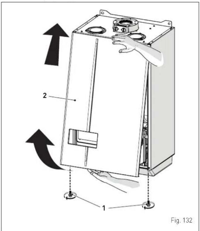
- use the tabs (3) to release the control panel (4)
- bring the panel forwards and downwards until it is horizontal
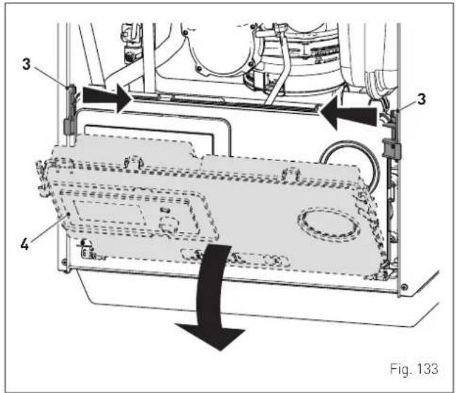
- close the gas valve
- loosen the screw of the "mains pressure" point (5) and connect a pressure gauge
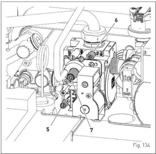
- open the gas valve
- power the boiler by setting the main switch to "ON"
Leave the appliance to stabilise, then:
- follow the procedure described in the section "TECHNICAL menu" up to "accessing the submenus"
- turn the encoder to select the "Chimney sweeper" (Chimney sweeper) submenu
- press the click encoder to confirm the selected submenu and access the relevant data display
![TECHNICAL Information [...] Plant solution [...] Technician param. [...] Chimney sweeper IoT [...]](/content/2026/05/855257/images/e13bf82995fbae5f952498fa30c2ffeeecbb21d35ba542b52b213b927041fdab.jpg)
- turn the encoder to select "En. Chimney Sweeper" (En.
Chimney Sweeper) row and press the click encoder to enter the modifiable data area
- turn the encoder to set the value to "Hi", press the click encoder to run the boiler at maximum power (Qmax)
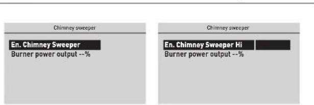
Fig. 137
- check that the gas supply pressure is as shown in the table below
| Type of gas G20 G31 | ||
| Pressure [mbar] 20 37 |
- measure the CO2 and check that it corresponds to the value in the table. If it does not correspond, adjust the "maximum power adjustment screw" (6) on the gas valve until you obtain the CO2 value shown in the table. Take any other necessary readings.
Once any necessary adjustments and readings have been made:
- turn the encoder to select "En. Chimney Sweeper" (En.
Chimney Sweeper) row and press the click encoder to enter the modifiable data area
- turn the encoder to set the value to "Low"; press the click encoder to run the boiler at minimum power (Qmin)
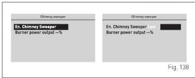
- measure the CO2 and check that it corresponds to the value in the table. If it does not correspond, adjust the "minimum power adjustment screw" (7) on the gas valve until you obtain the CO2 value shown in the table.
CO_2 values
| MURELLE.HT | CO_2 (G20) CO | 2 (G31) | ||
| Qmax(% ± 0,2) | Qmin(% ± 0,2) | Qmax(% ± 0,2) | Qmin(% ± 0,2) | |
| 25 | 9,38,8 | 10,010,0 | ||
| 30 | 9,09,0 | 10,010,0 | ||
| 35 | 9,59,0 | 10,310,3 | ||

CAUTION
This procedure MUST BE PERFORMED after replacing the gas valve following a fault.
7.8 Gas conversion
MURELLE.HT models can be converted from operating with G20 to G31 by installing the "Nozzle kit for G31" code 5185138 (for MURELLE.HT 25), 5185139 (for MURELLE.HT 30) and code 5185140 (for MURELLE.HT 35) to be ordered separately from the boiler.

CAUTION
The maintenance interventions described must ONLY be carried out the professionally qualified personnel.

WARNING
Before carrying out any interventions described:
- set the main system switch to "OFF"
- close the gas valve
- make sure that no hot parts inside the appliance are touched.
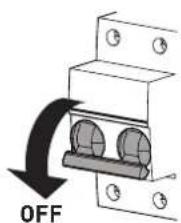
Fig. 139
7.8.1 Preliminary operations
To carry out the conversion:
- remove the screws (1), pull the front panel (2) forwards and release it from the top by lifting it
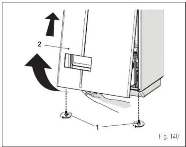
- unscrew the screws (3) and remove the cover (4)
- unscrew the screw (5) and remove the plate (6)
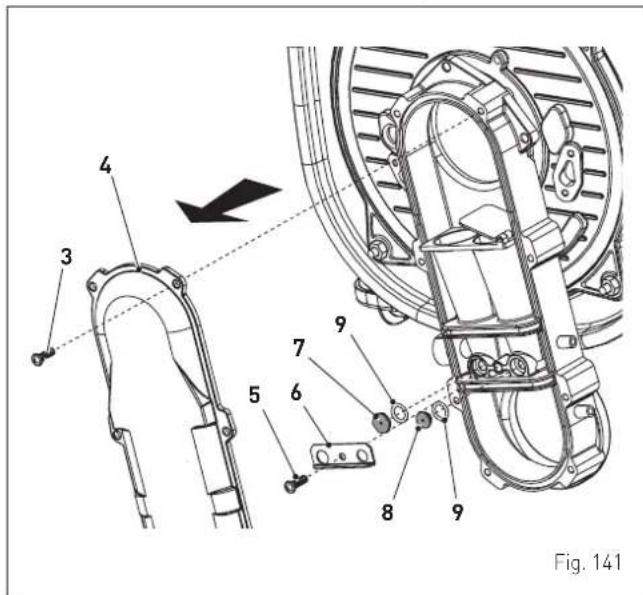
- replace the two distinct nozzles (7) and (8) and the related O-ring (9) with those provided in the conversion kit. Having two distinct nozzle heads avoids them being inverted during assembly
- refit the plate (6) and cover (4) following the above instructions in reverse order
- carry out the "Checks and adjustments" then refit the front panel (2), fixing it in place using the two screws (1).
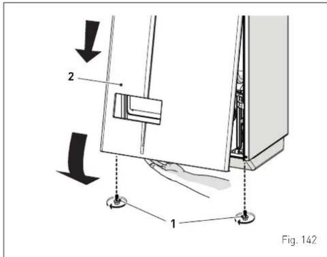

CAUTION
Conversion may ONLY be carried out by Professionally Qualified Personnel.

CAUTION
If the gas supply is changed from G20 to G31, mark the box on the TECHNICAL DATA PLATE.
G31 - 37 mbar
8.1 Adjustments
For the appliance to operate correctly and efficiently it is recommended that the User calls upon the services of a Professionally Qualified Technician to carry out ANNUAL maintenance.

CAUTION
- The maintenance interventions described must ONLY be carried out the professionally qualified personnel who MUST wear suitable protective safety equipment.
- Make sure that the system components and pipes are not hot (risk of burning).

WARNING
Before carrying out any interventions described:
- set the main system switch to "OFF"
- close the gas valve
- make sure that no hot parts inside the appliance are touched.
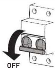
Fig. 143
8.2 External cleaning
8.2.1 Cleaning the cladding
When cleaning the cladding, use a cloth dampened with soap and water or alcohol for stubborn marks.

IT IS FORBIDDEN
to use abrasive products.
8.3 Cleaning the inside of the appliance
8.3.1 Removing components
To access the internal parts of the boiler:
- remove the screws (1), pull the front panel (2) forwards and release it from the top by lifting it
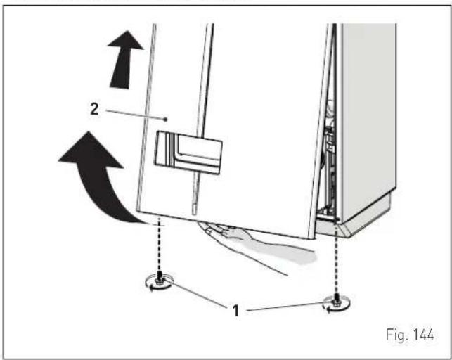
- use the tabs (3) to release the control panel (4)
- bring the panel forwards and downwards until it is horizontal
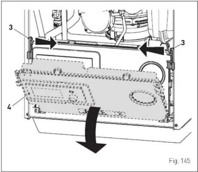
- remove the silicone tube (5) from the oversleeve
- loosen the clips (6) and extract the air inlet pipe (7)
- unscrew the swivel joint (8)
- extract the connectors (9) from the fan and disconnect the electrode cable (10)
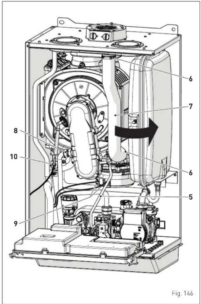
- Unscrew the four nuts (11) securing the combustion chamber door (12)
- pull the fan-sleeve-door assembly (13) forwards and remove it.
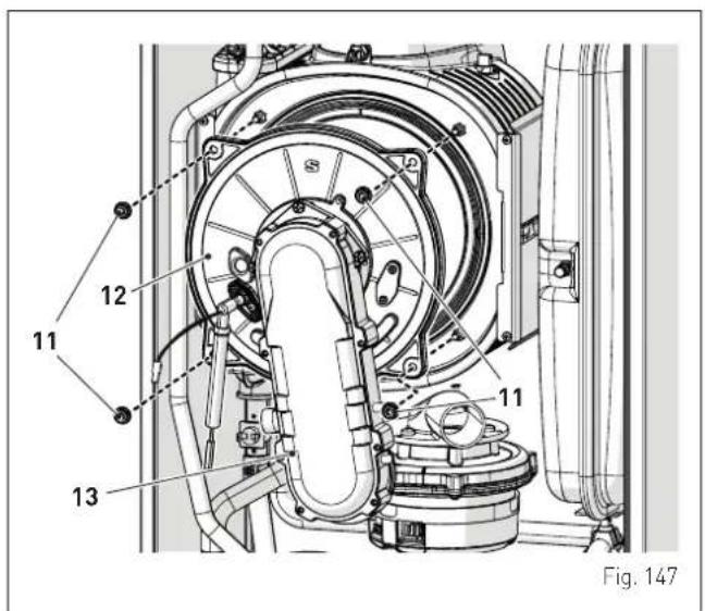

CAUTION
Work carefully when removing the assembly (14) to prevent any damage occurring to the internal insulation of the combustion chamber and the door seal.
8.3.2 Cleaning the burner and the combustion chamber
The combustion chamber and the burner do not require any particular maintenance. Simply brush them with a soft brush.
8.3.3 Checking the ignition/detection electrode
Check the state of the ignition/detection electrode and replace if necessary. Check the measurements as per the drawing whether the ignition/detection electrode is replaced or not.
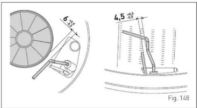
8.3.4 Final operations
After having cleaned the combustion chamber and the burner:
- remove any carbon residue
- check that the seal and the insulation of the door [12] to the combustion chamber are integral. Replace if necessary
- refit the assembly by carrying out the same operations for removal but in the reverse order and tighten the screws (11) of the door to the combustion chamber
- reconnect the connections to the fan and the electrode.
8.4 Checks
8.4.1 Checking the smoke duct
It is recommended that the user checks that the combustion air inlet duct and smoke outlet duct are integral and airtight.
8.4.2 Checking the expansion vessel pressure
It is recommended that the expansion vessel on the water side is drained and that the prefilling pressure is not less than 1 bar. If this is not the case, pressurize it to the correct value (see section "Expansion vessel").
Once the checks described above have been completed:
- refill the boiler as described in section "REFILL operations"
- check that the siphon has been filled correctly
- Start the boiler, activate the "Chimney sweeper function" and carry out a smoke analysis and/or measure the combustion efficiency
- refit the front panel securing it with the two screws which were removed previously.
8.5 Unscheduled maintenance
If replacing the electronic board, the user MUST set the parameters as indicated in the table and in the sequence shown.
| Setting for MURELLE.HT | PAR 01 PAR | 02 |
| Index showing boiler power in kW and type of boiler | Hydraulic configuration and system type | |
| MURELLE.HT 25 (Methane) 2 1 | ||
| MURELLE.HT 30 (Methane) 3 1 | ||
| MURELLE.HT 35 (Methane) 4 1 | ||
| MURELLE.HT 25 [GPL] 6 1 | ||
| MURELLE.HT 30 [GPL] 7 1 | ||
| MURELLE.HT 35 [GPL] 8 1 | ||
| MURELLE.HT 25 [I2E] 10 1 | ||
| MURELLE.HT 30 [I2E] 11 1 | ||
| MURELLE.HT 35 [I2E] 12 1 |
To enter "Parameter setting and display" refer to the indications provided in the specific section.
Once the parameters in the table have been set, you must carry out the entire phase of "Commissioning" described in the specific section.
refill the boiler as described in section "REFILL operations"
Checks and adjustments" described in the specific section.
8.6 Malfunction codes and possible solutions LIST OF MALFUNCTION/FAULT ALARMS
| Motor type | No. Fault Solution | |
| ALL 02 | Low water pressure in system- Restore pressure- Check for any leaks in the system | |
| ALL 03 | High water pressure in system- Empty the system via the drain valve on the hydraulic assembly and bring the pressure to approximately 1.2 bar | |
| ALL 04 | Domestic hot water sensor fault (return sensor fault for T models)- Check connections- Check the sensor is working | |
| ALL 05 | Delivery sensor fault- Check connections- Check the sensor is working | |
| ALL 06 | No flame detection | - Check the integrity of the electrode and check that it is not grounded- Check gas availability and pressure- Check the integrity of the gas valve and the card |
| ALL 07 | Sensor or safety thermostat intervenes- Check the sensor or thermostat connections- Deaerate the system- Check the bleed valve- Replace the sensor or the thermostat- Check that the pump impeller is not blocked | |
| ALL 08 | Fault in the flame detection circuit- Check the integrity of the electrode and check that it is not grounded- Check the integrity of the gas valve and the card |
| Motor type | No. Fault Solution | ||
| ALL 09 | No water circulating in the system | - Check the rotation of the pump rotor- Check the electrical connections- Replace the pump | |
| ALL 10 | Auxiliary sensor 1 fault | - Check PAR 02 "hydraulic configuration"- Check the electrical connection | |
| ALL 12 | Domestic hot water sensor fault in tank mode | - Set the parameter PAR 04 (Combustion configuration) to 0 | |
| ALL 13 | Smoke probe intervention | - Check the sensor is working- Replace the smoke probe | |
| ALL 14 | Smoke | probe fault | - Replace the smoke probe- Check the electrical connection of the smoke probe- Contact the Technical Assistance Centre |
| ALL 15 | Fan fault | - Check the fan rpm- Check the electronic circuit board | |
| ALL 19 | External sensor fault | - Check the sensor connection- Check the sensor is working | |
| ALL 20 | Boiler configuration failure (PAR 01 and PAR 02 not configured) | - Configure the boiler (see the section "Parameter setting and display") | |
| ALL 28 | Maximum number of consecutive resets reached | - Wait 1 hour and try unblocking the board again- Contact the Technical Assistance Centre | |
| ALL 30 | Return sensor fault (boiler sensor fault for T models) | - Replace the return probe- Check parameters- Contact the Technical Assistance Centre | |
| ALL 31 | PT1000 | sensor fault | - Replace the sensor- Contact the Technical Assistance Centre |
| ALL 32 | Auxiliary sensor 2 fault | - Check PAR 02 "hydraulic configuration"- Check the electrical connection | |
| ALL 37 | Fault due to low network voltage | - Check the voltage- Contact your network provider | |
| ALL 40 | Incorrect network frequency detected | - Contact your network provider | |
| ALL 41 | Flame loss more than 6 consecutive times | - Check the ignition/detection electrode- Check the gas supply (open valve)- Check mains gas pressure | |
| ALL 43 | Open Therm communication fault | - Check the OT electric connection | |
| ALL 46 | Mix zone thermostat intervention fault | - Check the mixer valve is working- Check the thermostat is working | |
| ALL 47 | Mix zone sensor fault | - Check the sensor connection- Check the sensor is working | |
| Motor type | No. Fault Solution | |
| ALL 48 | Mix zone configuration fault- Check that the system solution is correctly set (see the section "Displaying the set system solution") | |
| ALL 49 | Solar manifold probe fault- Check the sensor connection- Check the sensor is working | |
| ALL 50 | Solar hot water tank sensor fault- Check the sensor connection- Check the sensor is working | |
| ALL 51 | Solar system configuration fault- Check that the system solution is correctly set (see the section "Displaying the set system solution") | |
| ALL 52 | Preheating sensor fault- Check the sensor connection- Check the sensor is working | |
| ALL 53 | Preheating configuration fault- Check that the system solution is correctly set (see the section "Displaying the set system solution") | |
| ALL 54 | Hybrid kit system thermostat fault- Check the system, inputs and outputs are configured correctly | |
| ALL 55 | Hybrid kit sensor fault- Check the system, inputs and outputs are configured correctly | |
| ALL 58 | Heat pump lockout fault- | |
| ALL 59 | Heat pump or hybrid kit configuration fault- Check the system, inputs and outputs are configured correctly | |
| ALL 67 | Cascade manifold probe fault- Check the system, inputs and outputs are configured correctly | |
| ALL 68 | Cascade board communication fault- Check the system, inputs and outputs are configured correctly | |
| ALL 69 | Identical addresses in cascade fault- Check the system, inputs and outputs are configured correctly | |
| ALL 70 | Cascade stop general fault- Check the system, inputs and outputs are configured correctly | |
| ALL 71 | Generic fault with cascade module- Check the system, inputs and outputs are configured correctly | |
| ALL 72 | Incorrect positioning of the delivery sensor- Check delivery sensor operation and position | |
| ALL 98 | SW error, board start-up- Contact the Technical Assistance Centre | |
| ALL 99 | General board error | - Contact the Technical Assistance Centre |
| ALL 100 | Communication error with BMU- Contact the Technical Assistance Centre |
| Motor type | No. Fault Solution | |
| ALL 101 | Configuration error with Zone 1 | - Check the Zone 1 settings in the ZONE menu |
| ALL 102 | Configuration error with Zone 2 | - Check the Zone 2 settings in the ZONE menu |
| ALL 103 | Configuration error with Zone 3 | - Check the Zone 3 settings in the ZONE menu |
| ALL 104 | Configuration error with Zone 4 | - Check the Zone 4 settings in the ZONE menu |
| ALL 111 | Communication error with Zone room sensor 1 | - Check the RF concentrator wiring- Check the battery level of the room sensor 1 |
| ALL 112 | Communication error with Zone room sensor 2 | - Check the RF concentrator wiring- Check the battery level of the room sensor 2 |
| ALL 113 | Communication error with Zone room sensor 3 | - Check the RF concentrator wiring- Check the battery level of the room sensor 3 |
| ALL 114 | Communication error with Zone room sensor 4 | - Check the RF concentrator wiring- Check the battery level of the room sensor 4 |
| ALL 121 | Communication error with Zone Circuit 1 | - Contact the Technical Assistance Centre |
| ALL 122 | Communication error with Zone Circuit 2 | - Contact the Technical Assistance Centre |
| ALL 123 | Communication error with Zone Circuit 3 | - Contact the Technical Assistance Centre |
| ALL 124 | Communication error with Zone Circuit 4 | - Contact the Technical Assistance Centre |
| ALL 151 | Value reading error for Zone room sensor 1 | - Check the battery level of the room sensor 1 |
| ALL 152 | Value reading error for Zone room sensor 2 | - Check the battery level of the room sensor 2 |
| ALL 153 | Value reading error for Zone room sensor 3 | - Check the battery level of the room sensor 4 |
| ALL 154 | Value reading error for Zone room sensor 4 | - Check the battery level of the room sensor 4 |
9 ANNEXES
9.1 Boiler product board
 | |||
| MURELLE.HT | 25 | 30 | 35 |
| D.H.W load profile declared | XL | XL | XL |
| C.H. energy efficiency class |  |  |  |
| D.H.W. energy efficiency class |  |  |  |
| Heat output (kW) | 24 | 29 | 34 |
| C.H. annual energy consumption (GJ) | 40 | 48 | 56 |
| D.H.W. annual combustible consumption (GJ) | 18 | 18 | 18 |
| C.H. seasonal energy efficiency (%) | 93 | 93 | 93 |
| D.HW. energy efficiency (%) | 82 | 82 | 81 |
| Sound power dB(A) | 51 | 52 | 53 |
| Specific precautionary measures to be adopted at the time of assembly, installation or maintenance of the equipment are contained in the boiler instruction manualConforming to Annex IV (item 2) of the Delegated Regulations (EU) No. 811/2013 which supplements Directive 2010/30/EU | |||
9.2 Boiler technical sheet
| Information requirements for boiler space heaters, boiler combination heaters | ||||||||
| Model(s): MURELLE.HT 25 | ||||||||
| Condensing boiler: Yes | ||||||||
| Low-temperature boiler: Yes | ||||||||
| B11 boiler: No | ||||||||
| Cogeneration space heater: No | Equipped with a supplementary heater: | No | ||||||
| Combination heater: Yes | ||||||||
| Item | Symbol | Value | Unit | Item | Symbol | Value | Unit | |
| Nominal heat output for space heating | P_n | 24 | kW | Seasonal space heating energy efficiency | ns | 93 | % | |
| For boiler space heaters and boiler combination heaters: useful heat output | For boiler space heaters and boiler combination heaters: useful efficiency | |||||||
| At nominal heat output and high-temperature regimea | P_4 | 24,2 | kW | At nominal heat output and high-temperature regime (*) | n4 | 89,0 | % | |
| At 30% of nominal heat output and low-temperature regimeb | P_1 | 8,0 | kW | At 30% of nominal heat output and low-temperature regime (*) | n1 | 97,7 | % | |
| Auxiliary electricity consumption | Other items | |||||||
| At full load | el_max | 0,044 | kW | Standby heat loss | Pstby | 0,095 | kW | |
| At part load | el_min | 0,016 | kW | Ignition burner power consumption | Pign | 0 | kW | |
| In standby mode | PSB | 0,005 | kW | Emissions of nitrogen oxides Выбросы NOx | NOx | 34 | mg/kWh | |
| For combination heaters: | ||||||||
| Declared load profile | XL | Water heating energy efficiency | nwh | 82 | % | |||
| Daily electricity consumption Qelec | 0,184 | kWh | Daily fuel consumption | Qfuel | 23,739 | kWh | ||
| Contact details | Fonderie Sime S.p.A. Via Garbo 27, 37045 Legnago (VR) ITALIA | |||||||
| a. High-temperature regime means 60°C return temperature at heater inlet and 80°C feed temperature at heater outlet.b. Low-temperature regime means for condensing boilers 30°C, for low-temperature boilers 37°C and for other heaters 50°C return temperature. (*) The yield data have been calculated using the higher heating value. | ||||||||
| Model(s): MURELLE.HT 30 | ||||||||
| Condensing boiler: Yes | ||||||||
| Low-temperature boiler: Yes | ||||||||
| B11 boiler: No | ||||||||
| Cogeneration space heater: No | Equipped with a supplementary heater: | No | ||||||
| Combination heater: Yes | ||||||||
| Item | Symbol | Value | Unit | Item | Symbol | Value | Unit | |
| Nominal heat output for space heating | P_n | 29 | kW | Seasonal space heating energy efficiency | ns | 93 | % | |
| For boiler space heaters and boiler combination heaters: useful heat output | For boiler space heaters and boiler combination heaters: useful efficiency | |||||||
| At nominal heat output and high-temperature regimea | P_4 | 29,1 | kW | At nominal heat output and high-temperature regime (*) | n4 | 88,7 | % | |
| At 30% of nominal heat output and low-temperature regimeb | P_1 | 9,6 | kW | At 30% of nominal heat output and low-temperature regime (*) | n1 | 97,7 | % | |
| Auxiliary electricity consumption | Other items | |||||||
| At full load | el_max | 0,054 | kW | Standby heat loss | Pstby | 0,101 | kW | |
| At part load | el_min | 0,018 | kW | Ignition burner power consumption | Pign | 0 | kW | |
| In standby mode | PSB | 0,005 | kW | Emissions of nitrogen oxides Выбросы NOx | NOx | 41 | mg/kWh | |
| For combination heaters: | ||||||||
| Declared load profile | XL | Water heating energy efficiency | nwh | 82 | % | |||
| Daily electricity consumption Qelec | 0,158 | kWh | Daily fuel consumption | Qfuel | 23,934 | kWh | ||
| Contact details | Fonderie Sime S.p.A. Via Garbo 27, 37045 Legnago (VR) ITALIA | |||||||
| a. High-temperature regime means 60°C return temperature at heater inlet and 80°C feed temperature at heater outlet.b. Low-temperature regime means for condensing boilers 30°C, for low-temperature boilers 37°C and for other heaters 50°C return temperature. (*) The yield data have been calculated using the higher heating value. | ||||||||
| Model(s): MURELLE.HT 35 | ||||||||
| Condensing boiler: Yes | ||||||||
| Low-temperature boiler: Yes | ||||||||
| B11 boiler: No | ||||||||
| Cogeneration space heater: No | Equipped with a supplementary heater: | No | ||||||
| Combination heater: Yes | ||||||||
| Item | Symbol | Value | Unit | Item | Symbol | Value | Unit | |
| Nominal heat output for space heating | P_n | 34 | kW | Seasonal space heating energy efficiency | ns | 93 | % | |
| For boiler space heaters and boiler combination heaters: useful heat output | For boiler space heaters and boiler combination heaters: useful efficiency | |||||||
| At nominal heat output and high-temperature regimea | P_4 | 33,9 | kW | At nominal heat output and high-temperature regime (*) | η4 | 88,3 | % | |
| At 30% of nominal heat output and low-temperature regimeb | P_1 | 11,2 | kW | At 30% of nominal heat output and low-temperature regime (*) | η1 | 97,7 | % | |
| Auxiliary electricity consumption | Other items | |||||||
| At full load | el_max | 0,060 | kW | Standby heat loss | Pstby | 0,113 | kW | |
| At part load | el_min | 0,019 | kW | Ignition burner power consumption | Pign | 0 | kW | |
| In standby mode | PSB | 0,005 | kW | Emissions of nitrogen oxides Выбросы NOx | NOx | 41 | mg/kWh | |
| For combination heaters: | ||||||||
| Declared load profile | XL | Water heating energy efficiency | nwh | 81 | % | |||
| Daily electricity consumption Qelec | 0,183 | kWh | Daily fuel consumption | Qfuel | 24,350 | kWh | ||
| Contact details | Fonderie Sime S.p.A. Via Garbo 27, 37045 Legnago (VR) ITALIA | |||||||
| a. High-temperature regime means 60°C return temperature at heater inlet and 80°C feed temperature at heater outlet.b. Low-temperature regime means for condensing boilers 30°C, for low-temperature boilers 37°C and for other heaters 50°C return temperature. (*) The yield data have been calculated using the higher heating value. | ||||||||
sime
Fonderie Sime S.p.A - Via Garbo, 27 - 37045 Legnago (Vr)
Tel. +39 0442 631111 - Fax +39 0442 631292 - www.sime.it

- RANGE RATED CERTIFICATION
- WARNINGS
- IT IS FORBIDDEN
- COMPLIANCE
- SYMBOLS
- WARNING
- ELECTRICAL HAZARD
- CAUTION
- MANUAL STRUCTURE
- USER INSTRUCTIONS
- DESCRIPTION OF THE APPLIANCE
- INSTALLATION AND SERVICING INSTRUCTIONS
- TABLE OF CONTENTS
- USING THE BOILER MURELLE.HT 8
- SHUTDOWN 13
- MAINTENANCE 14
- DISPOSAL 14
- USING THE BOILER MURELLE.HT
- Control panel
- Start-up
- Preliminary checks
- Ignition
- Settings using the MODE function
- Domestic hot water
- Heating
- Fault warnings
- Time Programming
- SHUTDOWN
- Temporary shutdown
- Shutting down for long periods
- MAINTENANCE
- Adjustments
- External cleaning
- Cleaning the cladding
- DISPOSAL
- Disposal of the equipment (European Directive 2012/19/EU)
- DESCRIPTION OF THE APPLIANCE 16
- DESCRIPTION OF THE APPLIANCE
- Characteristics
- Check and safety devices
- Identification
- Technical Data Plate
- Structure
- Sensors
- Correspondence of Temperature Detected/Resistance
- Expansion vessel
- (\*) Conditions of:
- Circulation pump
- Control panel
- Wiring diagram
- INSTALLATION 26
- COMMISSIONING 51
- MAINTENANCE 73
- ANNEXES 77
- sime 6 INSTALLATION
- Receiving the product
- Dimensions and weight
- Handling
- Installation room
- New installation or installation of a replacement appliance
- Cleaning the system
- Water system treatment
- Boiler installation
- Plumbing connections
- Plumbing accessories (optional)
- Condensate outlet/collection
- Gas supply
- Smoke outlet and combustion air inlet
- Coaxial duct ( 60/100mm and 80/125mm)
- Separate ducts ( 60mm and 80mm)
- Smoke outlet
- Combustion air inlet
- Separate ducts ( 80mm) with duct kit C(10)3
- Electrical connections
- External temperature sensor
- Procedure for selecting the climatic curve
- Chrono-thermostat or Air Thermostat
- Installing the WiFi antenna
- System solutions
- Quick boiler system type configuration
- Plant solution diagrams with zone room thermostat
- PARAMETER SETTINGS REQUIRED FOR HEAT PUMP
- SHP ECO EV Heat Pump
- SHP M PRO Heat Pump
- Plant solution diagrams with wireless room probes and radio-frequency receiver
- Displaying the set system solution
- Refilling or emptying
- REFILL operations
- Remove the front panel:
- Domestic hot water circuit:
- Heating circuit:
- EMPTYING operations
- Boiler:
- Preliminary operations
- Before commissioning
- Main control panel display and settings
- Settings using the MODE function
- Domestic hot water
- Heating
- Fault warnings
- Time Programming
- Navigating from the MODE function
- Settings under the MENU function
- GENERAL SETTINGS menu
- INFORMATION menu
- TECHNICAL menu
- Navigating from the MENU function
- Settings under the ZONE function
- INFORMATION menu
- SETTINGS menu
- CONFIGURATION menu
- Navigating from the ZONE function
- Parameter setting and display
- List of parameters
- Fault / malfunction codes
- Checks and adjustments
- Chimney sweeper function
- Gas conversion
- Preliminary operations
- Adjustments
- External cleaning
- Cleaning the cladding
- Cleaning the inside of the appliance
- Removing components
- Cleaning the burner and the combustion chamber
- Checking the ignition/detection electrode
- Final operations
- Checks
- Checking the smoke duct
- Checking the expansion vessel pressure
- Unscheduled maintenance
- Malfunction codes and possible solutions LIST OF MALFUNCTION/FAULT ALARMS
- ANNEXES
- Boiler product board
- Boiler technical sheet
- sime
Brand : SIME
Model : MURELLE.HT
Category : Water heaters