
SDAT-MHS-M100-1L-SV-E-0.3-M8 - Uncategorized Festo - Free user manual and instructions
Find the device manual for free SDAT-MHS-M100-1L-SV-E-0.3-M8 Festo in PDF.


| Product Type | Position Transmitter (Magnetic Proximity Sensor) |
| Model | SDAT-MHS-M100-1L-SV-E-0.3-M8 |
| Brand | Festo |
| Sensing Range | 100 mm |
| Output Signals | Analogue 0-10 V, Switching Output PNP 24 V, IO-Link |
| Power Supply | 15-30 V DC (PELV, Class 2) |
| Current Consumption | Max. 160 mA (4.8 W) |
| Resolution | 0.05 mm |
| Switching Output Repetition Accuracy | 0.1 mm |
| Analogue Output Sensitivity | 90 mV/mm (for M100) |
| Typical Linearity Error | ±0.25 mm |
| Max. Traverse Velocity | 3 m/s |
| Sampling Interval | 1 ms |
| Communication Mode | IO-Link COM3 (230.4 kbaud) |
| Connection | M8x1 4-pin plug with 0.3 m cable |
| Mounting | T-slot, any orientation; tightening torque 0.5 Nm |
| Degree of Protection | IP65/IP68 (IP68: 24 h test) |
| Ambient Temperature | -25 °C to +70 °C |
| Materials | Halogen-free, housing: PA-reinforced, polyester, stainless steel, nickel-plated brass |
| Certifications | UL/CSA (NRKH, NRKH7, E232949) |
| Safety | Use only with PELV circuits; must be supplied from NEC/CEC Class 2 source with isolating transformer and secondary fuse 1 A |
| Maintenance | Keep dry; clean with dry cloth if necessary; do not use solvents |
| Repairability | No user-serviceable parts; replace entire unit if faulty |
| Weight | Approx. 0.1 kg (estimated) |
Frequently Asked Questions - SDAT-MHS-M100-1L-SV-E-0.3-M8 Festo
User questions about SDAT-MHS-M100-1L-SV-E-0.3-M8 Festo
0 question about this device. Answer the ones you know or ask your own.
Ask a new question about this device
Download the instructions for your Uncategorized in PDF format for free! Find your manual SDAT-MHS-M100-1L-SV-E-0.3-M8 - Festo and take your electronic device back in hand. On this page are published all the documents necessary for the use of your device. SDAT-MHS-M100-1L-SV-E-0.3-M8 by Festo.
USER MANUAL SDAT-MHS-M100-1L-SV-E-0.3-M8 Festo
natural_image
Illustration of five different mechanical components with no visible text or symbolsFESTO
Operating instructions
Translation of the original instructions
Table of contents
1 About this document.... 4
1.1 Applicable Documents.... 4
2 Safety....4
2.1 General safety instructions....4
2.2 Intended use.... 4
2.3 Training of qualified personnel....4
2.4 UL/CSA certification.... 4
3 Additional information....5
4 Product overview.... 5
4.1 Design....5
4.2 Function.... 5
4.2.1 Analogue output....6
4.2.2 Switching functions and switching logic....8
4.2.3 Switching output operating mode (SIO).... 10
4.2.4 IO-Link operating mode.... 10
5 Mounting....11
5.1 Electrical installation.... 11
5.2 Mechanical installation.... 12
6 Commissioning 13
6.1 Switch on the position transmitter.... 13
6.2 Setting Set-up mode.... 13
6.3 Scaling analogue signal.... 14
6.4 Program switching output....15
6.4.1 Set window comparator.... 15
6.4.2 Adjusting proximity switch.... 16
6.4.3 Set hysteresis comparator.... 17
6.4.4 Inverting switching logic....17
6.4.5 Block/unblock operating key.....18
6.4.6 Programming IO-Link output.... 18
7 Operation.... 18
7.1 Magnetic direction detection and magnetic direction correction.... 18
7.2 LED displays in normal operation....19
7.3 Reset position transmitter to factory setting.... 20
7.4 Analogue output and switching function operation....21
8 Malfunctions....22
8.1 Diagnostics via LED....22
8.2 General malfunctions.... 22
9 Disassembly.... 23
10 Technical data....23
10.1 General....23
10.2 IO-Link.... 25
10.3 I-Port.... 30
10.4 Technical data for UL/CSA certification.... 30
1 About this document
1.1 Applicable Documents

All available documents for the product → www.festo.com/sp.
2 Safety
2.1 General safety instructions
-Only use the product in its original condition without unauthorised modifications.
-Only use the product if it is in perfect technical condition.
- The product may generate high frequency interference, which may require interference suppression measures in residential areas.
2.2 Intended use
The position transmitter is intended for contactless detection of the piston position of magnetic proximity sensing drives and grippers.
-Use the position transmitter only for suitable Festo drives and grippers.
-Do not place magnetic objects in the immediate vicinity of the position transmitter.
2.3 Training of qualified personnel
Work on the product may only be carried out by qualified personnel who can evaluate the work and detect dangers. The qualified personnel have skills and experience in dealing with electropneumatic (open-loop) control technology.
2.4 UL/CSA certification
In combination with the UL inspection mark on the product, the information in this section must also be observed in order to comply with the certification conditions of Underwriters Laboratories Inc. (UL) for USA and Canada.
UL approval information
| Product category code NRKH, NRKH7 | |
| File number E232949 | |
| Considered standards UL 60947-1, UL 60947-5-2, CSA C22.2 No. 60947-1, CSA C22.2 No. 60947-5-2 | |
| UL mark |  Ind. Cont. EQ. (Industrial Control Equipment)2MD1 Ind. Cont. EQ. (Industrial Control Equipment)2MD1 |
Tab. 1: UL/CSA approval information
Product overview
- Technical data and environmental conditions may be subject to change in order to comply with Underwriters Laboratories Inc. (UL) certification requirements for the USA and Canada. 10.4 Technical data for UL/CSA certification
- Only for connection to a NEC/CEC Class 2 supply.
- The device shall be supplied from an isolating transformer having a secondary listed fuse rated 1 A.
3 Additional information
- Contact the regional Festo contact if you have technical problems → www.festo.com.
- Accessories and spare parts → www.festo.com/catalogue.
4 Product overview
4.1 Design
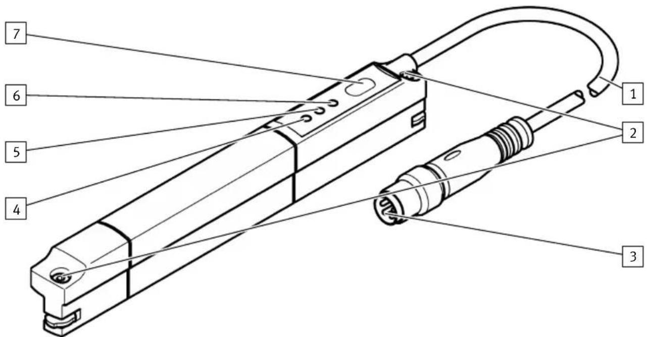
Fig. 1: Design of SDAT-MHS
1 Connecting cable
5 Green LED: ready status display
2 Retaining screws
6 Yellow LED: switching status display
3 M8 plug, rotatable
7 Operating key
4 Red LED: status indicator
4.2 Function
The position transmitter detects the magnetic field of the piston magnet and continuously senses the piston movement in the sensing range.
The following output signals are available:
- analogue voltage signal: 0 ... 10 V
- programmable switching output: 24 V
- IO-Link communication mode 4.2.4 IO-Link operating mode
4.2.1 Analogue output
The analogue output provides an output signal 0 ... 10 V.
- The output signal is proportional to the path of the piston stroke in the sensing range.
-The output signal can be scaled.
-The direction of increase of the analogue output signal can be inverted. - The analogue output signal in the switching output operating mode is made available parallel and independent of the position value output of the switching output.
-The analogue output is switched off in the IO-Link operating mode.
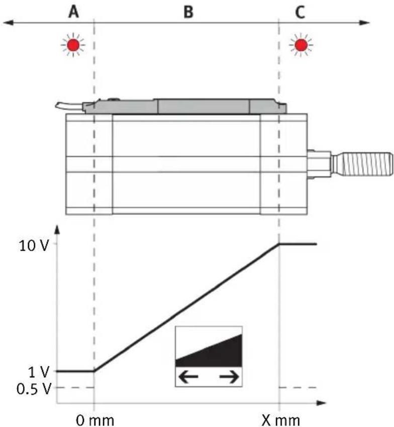
Fig. 2: Characteristic curve of the analogue output
X = maximum length of the sensing range
| Signal Description | Range | 1) |
| 0 V | - IO-Link operation- Error, e.g. cable break, parameter error | - |
| 0.5 V | - Piston is outside the sensing range after switching on the operating voltage | A, C |
| 1 V | - The piston has left the sensing range in the direction of the falling output current | A |
| >1 V ... < 10 V | - Piston is within the sensing range B | |
| 10 V | - Piston has left the sensing range in the direction of the rising output voltage | C |
1) Range Fig. 2, range A and C: red LED on
Tab. 2: Output signal of the analogue output
i
The analogue output is switched off during active IO-Link communication. The output voltage is 0 V.
Scaling of the analogue signal
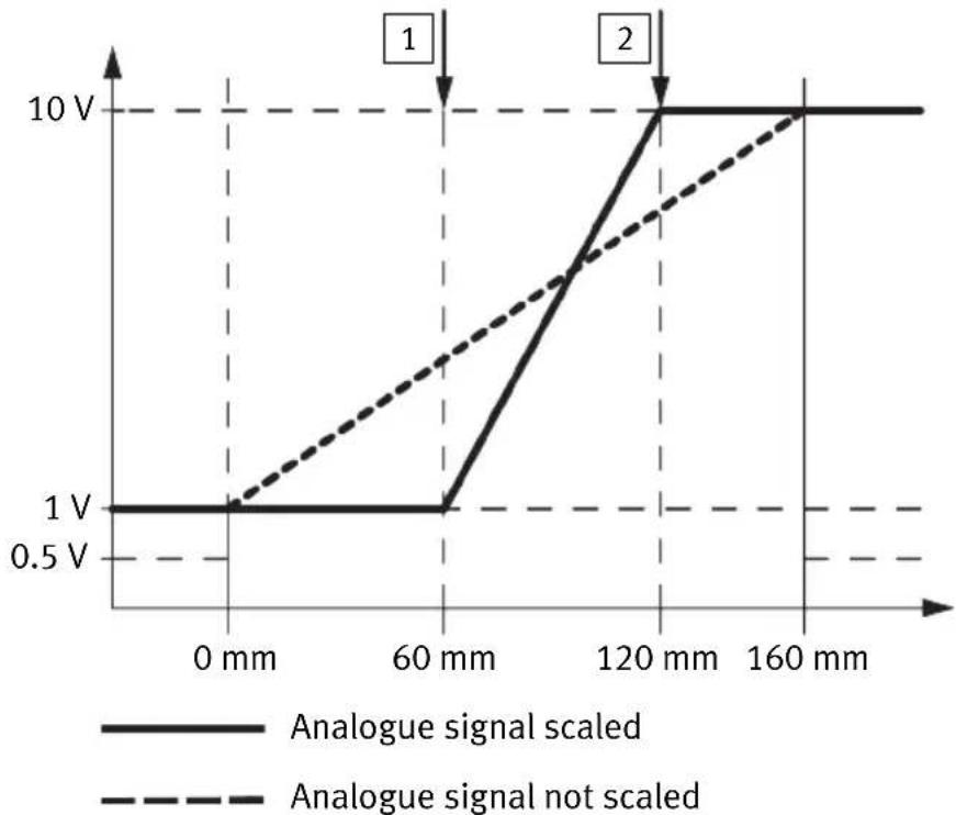
The analogue output signal is assigned by default to the complete sensing range. If only a part of the sensing range is to be used, the analogue value output can be scaled to the sensing range in use. The resolution and the repetition accuracy are not improved by scaling.
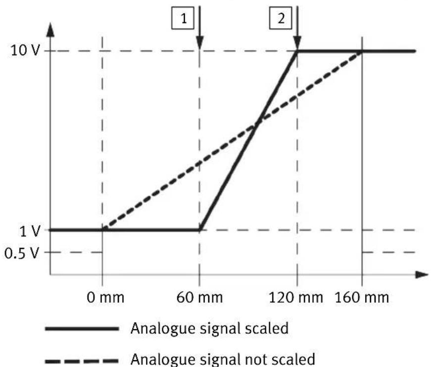
line
| Distance | Analogue signal scaled | Analogue signal not scaled | | -------- | ------------------------ | --------------------------- | | 0 mm | 1 V | 1 V | | 60 mm | 1 V | ~3 V | | 120 mm | 10 V | ~6 V | | 160 mm | 10 V | 10 V |Fig. 3: Scaling of the analogue signal using the SDAT-MHS-M160 as an example
① Teach-in point 1 ② Teach-in point 2
4.2.2 Switching functions and switching logic
4.2.2.1 Window comparator
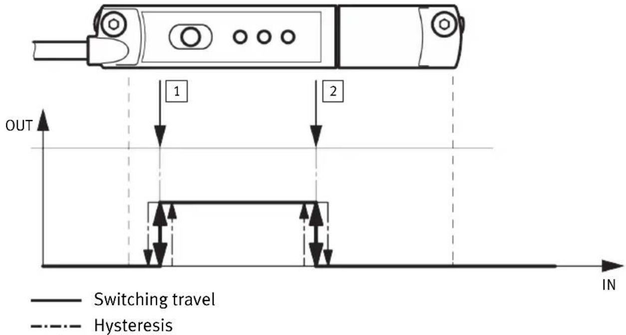
Fig. 4: Window comparator
① Teach-in point 1 ② Teach-in point 2
Teach-in points 1 and 2 are linked to the window comparator function.
-The position of the teach points determines the window width.
-Hysteresis is not selectable or preset.
4.2.2.2 Proximity switch
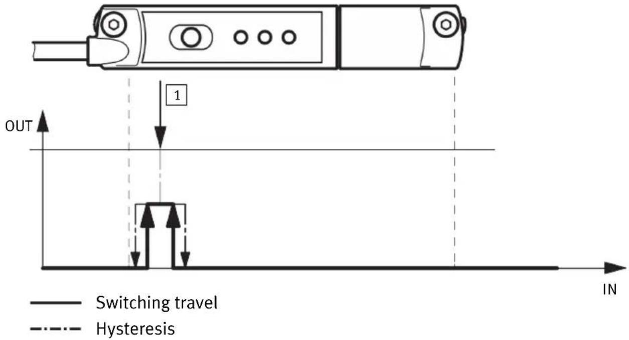
Fig. 5: Proximity switch
1 Teach-in point
The proximity switch function consists of a switching path and hysteresis. Hysteresis serves to suppress switching signals in the event of fluctuations around the switching point.
- The teach-in value is the centre of the switching path.
- The switching path and the hysteresis are not adjustable. Values for the switching path and the hysteresis are stored that correspond to a typical electronic proximity switch on a typical drive.
4.2.2.3 Hysteresis comparator
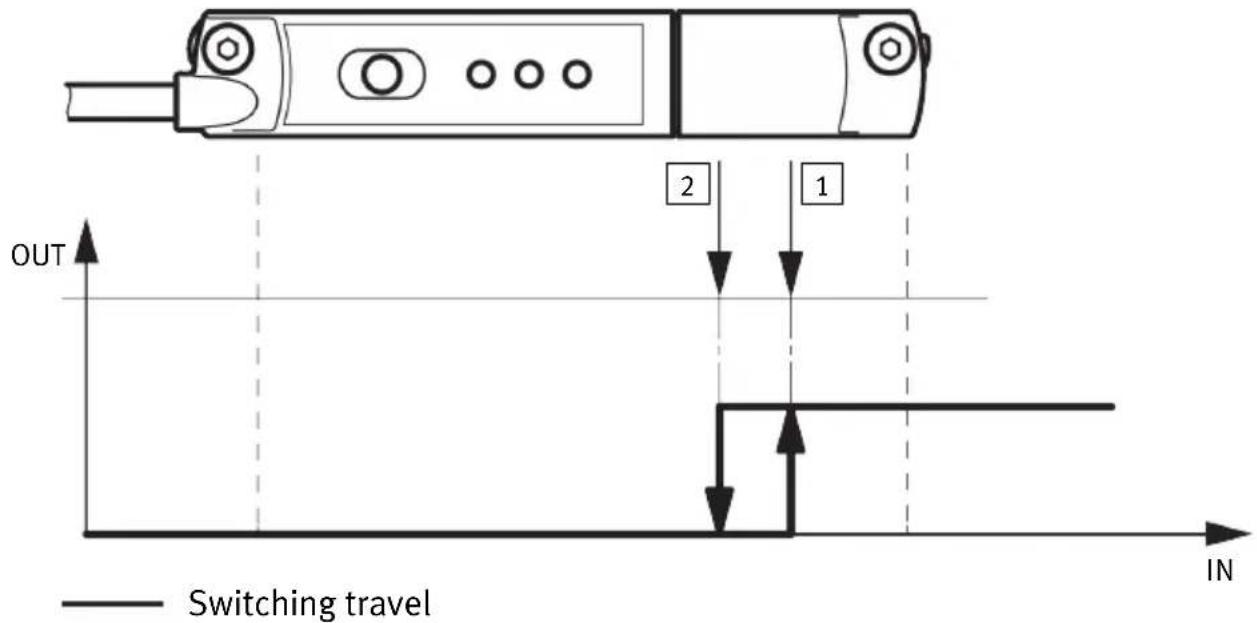
Fig. 6: Hysteresis comparator
① Teach-in point 1 ② Teach-in point 2
Teach-in points 1 and 2 are linked to the hysteresis comparator function.
- Teach-in point 1 (ON) is the switch-on point, teach-in point 2 (OFF) is the reset point.
- Teach-in point 2 establishes the size of the hysteresis.
4.2.2.4 Switching logic
The switching logic normally open (NO) is set as the default. If the switching logic normally closed (NC) is selected, the function of the switching output is inverted.
4.2.3 Switching output operating mode (SIO)
If the IO-Link/switching output is operated as a switching output, only 1 binary channel can be programmed. The switching output operating mode must be programmed actively via the Set-up mode
→ 6.2 Setting Set-up mode.
- The window comparator, the proximity switch or the hysteresis comparator function are programmable.
-The normally closed (NC) or the normally open (NO) switching logic can be selected.
- Programming via the IO-Link protocol (channel BDC1) or the operating key on the device.
-Display switching output ON: the yellow LED is on.
- Output signal 24 V DC (PNP).
i
Even if the analogue output has been scaled, the switching output can still be programmed over the entire sensing range.
4.2.4 IO-Link operating mode
Programmed switching signals and the continuous position values (digitally coded analogue values) are transferred in the IO-Link operating mode.
Mounting
- Proximity switches, window comparators or hysteresis comparators can be programmed separately on 4 binary channels.
- The continuous position values are always transferred parallel and independently of the position value output of the binary channels.
- Every channel can be set to be normally closed (NC) or normally open (NO).
- The data transfer is serially and digitally coded in the IO-Link protocol.
- Process data: 12 bit for position data and 4 bit for binary channels 10 Technical data.
- Unshielded standard cables up to 20 m in length can be used.
- The device description file IODD for every device length www.festo.com/sp.
-Parameters and function in accordance with Smart-Sensor profile. - The optional block parameterisation and Data Storage functions are supported.
- IO-Link operation display: the green LED flashes.
–The direction of the process data values (PDV) can be inverted.
The PDVs are minimum (standard) or maximum (inverted) and end of the sensor cable.
5 Mounting
5.1 Electrical installation

WARNING
Risk of injury due to electric shock.
- For the electrical power supply, use only PELV circuits in accordance with IEC 60204-1/EN 60204-1 (Protective Extra-Low Voltage, PELV).
- Observe the general requirements of IEC 60204-1/EN 60204-1 for PELV circuits.
-
Only use voltage sources that ensure a reliable electric separation from the mains network in accordance with IEC 60204-1/EN 60204-1.
-
Switch off the operating voltage.
-
Connect the M8 plug to the connecting cable of the higher-order controller.
- Max. tightening torque for the union nut of the plug: 0.3 Nm.
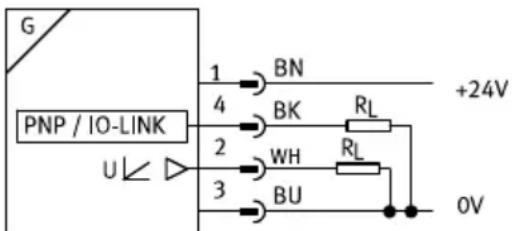
Fig. 7: Circuit diagram
| Pin Allocation Plug | ||
| 1 Operating voltage +24 V DC M8x1, 4-pin | 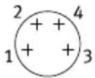 | |
| 2 Analogue output 0 ... 10 V | ||
| 3 0 V | ||
| 4 IO-Link/switching output (C/Q line) | ||
Tab. 3: Pin allocation of plug connection
Mounting
5.2 Mechanical installation
Any mounting position can be used.
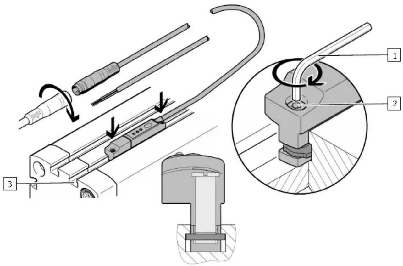
Fig. 8: Mechanical installation
1 Hexagon socket spanner
3 T-slot
2 Retaining screw
- Push the position transmitter into the T-slot of the drive.
- Move the piston to an end position of the application.
- Push the position transmitter in the direction of the piston until the red LED goes out.
- Hand-tighten the retaining screw.
-Max. tightening torque: 0.5 Nm - Tool: internal hexagon socket key (size 1.5 mm).
6 Commissioning
6.1 Switch on the position transmitter
- Switch on the operating voltage.
The LEDs light depending on the position of the piston → Tab. 5 LED displays in normal operation.
The position transmitter is ready for operation.
| Parameters Factory setting | |
| Switching function None | |
| Switching logic Normally open contact (N/O) | |
| Scaling Total sensing range |
Tab. 4: Factory settings of the position transmitter
6.2 Setting Set-up mode
- Press the operating key 3 times within 3 s.
Set-up mode active: the green LED and the yellow LED flash simultaneously.
i
If, after entering the Set-up mode, programming is not completed within 60 s, the position transmitter automatically switches to the operating mode.
6.3 Scaling analogue signal
line
| Distance | Analogue signal scaled | Analogue signal not scaled | | -------- | ------------------------ | --------------------------- | | 0 mm | 1 V | 1 V | | 60 mm | 1 V | ~3 V | | 120 mm | 10 V | ~7 V | | 160 mm | 10 V | 10 V |Fig. 9: Scaling the analogue signal using the SDAT-MHS-M160 as an example
① Teach point 1 ② Teach point 2
Requirement: the piston is in the sensing range (red LED off).
-
Switch to the Set-up mode.
-
Press the operating key 5 times in succession.
The analogue output can be scaled: the green LED flashes 5 times in quick succession within 2 s.
-
Move the piston to the starting point of the sensing range.
-
Press the operating key.
Teach point 1 is defined: the starting point of the sensing range at 0 V.
The green LED continues flashing, the yellow LED flashes at 1 Hz.
-
Move the piston to the end point of the sensing range.
-
Press the operating key.
Teach point 2 is defined: the end point of the sensing range at 10 V.
The position transmitter switches to the operating mode.
i
To invert the direction of increase of the analogue signal: set teach point 2 (10 V) on the cylinder axis before teach point 1 (0 V).
6.4 Program switching output
6.4.1 Set window comparator
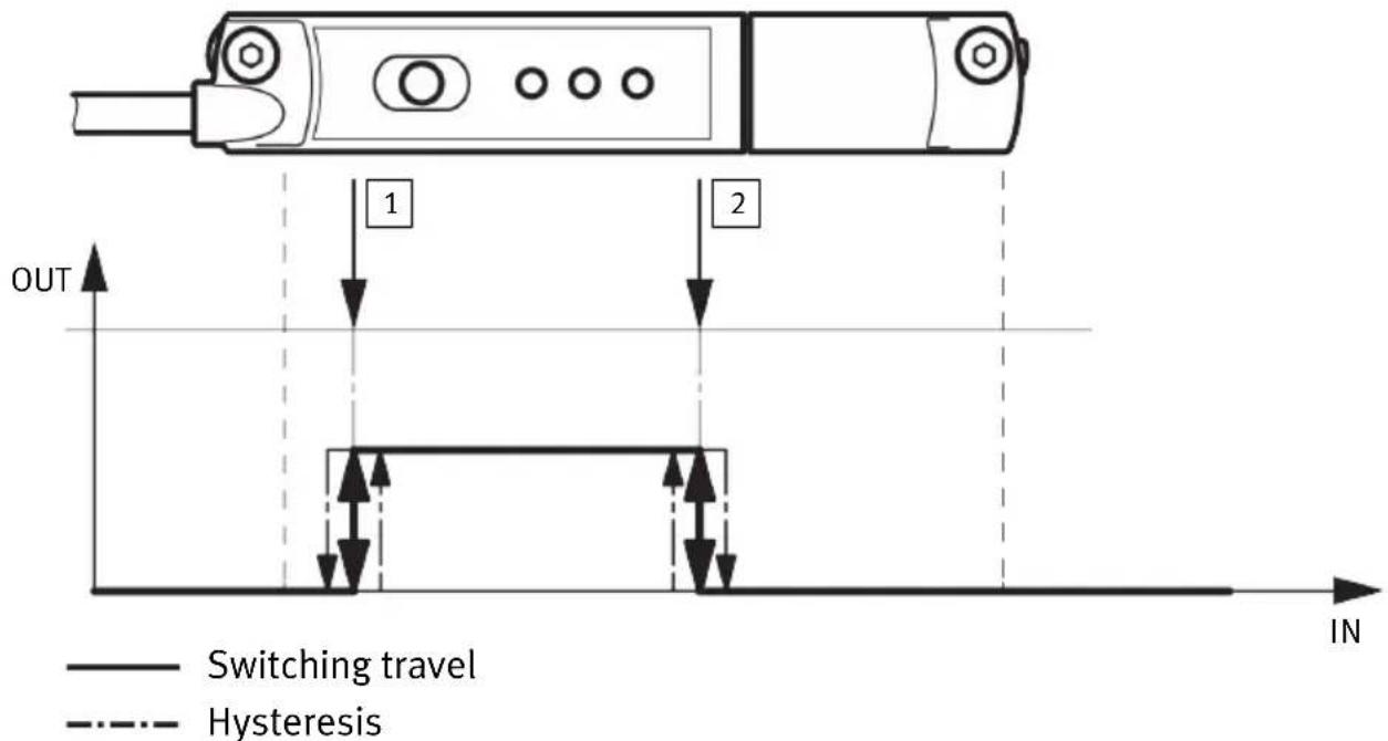
Fig. 10: Window comparator
① Teach point 1 ② Teach point 2
Requirement: the piston is in the sensing range (red LED off).
-
Switch to the Set-up mode → 6.2 Setting Set-up mode.
-
Press the operating key once.
The green LED flashes once within 2 s.
-
Move the piston to the first switching point (teach point 1).
-
Press the operating key once.
Switching point 1 is set.
The green LED continues flashing, the yellow LED flashes at 1 Hz.
-
Move the piston to the second switching point (teach point 2).
-
Press the operating key once.
Switching point 2 is set.
The position transmitter switches to the operating mode.
Commissioning
6.4.2 Adjusting proximity switch
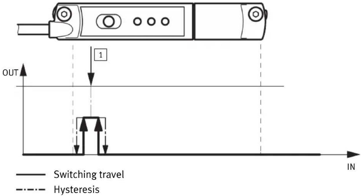
Fig. 11: Proximity switch
1 Teach point
Requirement: the piston is in the sensing range (red LED off).
-
Switch to the Set-up mode → 6.2 Setting Set-up mode.
-
Press the operating key twice.
The green LED flashes 2 times quickly within 2 s.
-
Move the piston to the first switching point (teach point 1).
-
Press the operating key once.
Switching point 1 is set.
The position transmitter switches to the operating mode.
6.4.3 Set hysteresis comparator
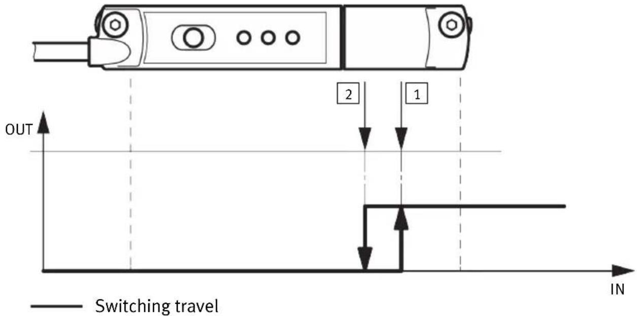
Fig. 12: Set hysteresis comparator
① Teach point 1 ② Teach point 2
Requirement: the piston is in the sensing range (red LED off).
-
Switch to the Set-up mode → 6.2 Setting Set-up mode.
-
Press the operating key 3 times.
The green LED flashes 3 times quickly within 2 s.
-
Move the piston to the switch-on point (teach point 1).
-
Press the operating key once.
The switch-on point is established.
The green LED continues flashing, the yellow LED flashes at 1 Hz.
-
Move the piston to the reset point (teach point 2).
-
Press the operating key once.
The reset point is established.
The position transmitter switches to the operating mode.
6.4.4 Inverting switching logic
The switching logic can be inverted from N/C to N/O and vice versa.
-
Switch to the Set-up mode → 6.2 Setting Set-up mode.
-
Press the operating key 4 times.
The green LED flashes 4 times quickly within 2 s.
The yellow LED lights: the currently set switching logic is N/C. The yellow LED is off: the currently set switching logic is N/O.
- Press the operating key once.
The switching logic is inverted. The position transmitter switches to the operating mode.
6.4.5 Block/unblock operating key
In IO-Link mode, the operating key is always blocked.
In the switching output operating mode, the operating key is unlocked by default. However, in the
IO-Link mode the operating key can be blocked for the switching output mode:
-
Start IO-Link communication.
-
Select key lock for switching output operating mode in the IO-Link parameter menu:
-Device access block
-Local user interface block
LED display with blocked operating key
-If the operating key is pressed, the green LED flashes for 3 s at 3 Hz.
- The yellow LED displays the current status of the switching output.
- The red LED only lights if the piston is outside the sensing range.
6.4.6 Programming IO-Link output
The IO-Link function cannot be set with the operating keys on the device. All settings for set-up, commissioning and parameterisation are made in the higher-level controller of the IO-Link master.
-
Upload the IODD device description file belonging to the device to the interpreter of the IO-Link master.
-
Connect the IO-Link/switching output to the IO-Link master.
-
Program the device Operating instructions for the IO-Link master.
i
An error during commissioning is displayed on the user interface of the IO-Link master and the programming option is blocked.
7 Operation
7.1 Magnetic direction detection and magnetic direction correction
During initial commissioning or after a reset to factory settings, the position transmitter outputs the signals directly using the currently detected magnetic direction.
The magnetic direction detection and, with it, the signal curve are corrected during continuing operation in the following cases:
- The position transmitter was placed in operation in a position in which it was not possible to detect a correct magnetic direction, e.g. due to ferromagnetic materials near the sensor or within the drive or gripper.
- The position transmitter was rotated 180^ in the slot after the magnetic direction was detected as stable.
i
Brief error signals may be detected at the sensor output if automatic correction of the magnetic direction detection is required 8.2 General malfunctions.
7.2 LED displays in normal operation
| LED display Description | |||
| Yellow Green Red | |||
  ○Green LED: onRed LED: off ○Green LED: onRed LED: off | Ready for operation:- Analogue output function or switching output operating mode.- Piston within the sensing range. | ||
  ○Green LED: flashing at 1 Hz ○Green LED: flashing at 1 Hz | Ready for operation:- IO-Link operating mode. | ||
  ○Yellow LED: onGreen LED: onRed LED: off ○Yellow LED: onGreen LED: onRed LED: off | Ready for operation:- Switching output switched.- Piston in the range of a programmed function. | ||
  ○Green LED: flashes 3 s at3 Hz when the operating key ispressed ○Green LED: flashes 3 s at3 Hz when the operating key ispressed | Status indicator:- Operating key blocked. | ||
   Red LED: on Red LED: on | Status indicator:- Piston outside the sensing range. | ||
Tab. 5: LED displays in normal operation
Query configuration
The currently set configuration can be queried in the Set-up mode.
-
Switch to the Set-up mode → 6.2 Setting Set-up mode.
-
Press the operating key 6 times.
The yellow, green and red LEDs flash cyclically according to the current configuration
→ Tab. 6 Status indicators in the Set-up mode.
- To terminate the query, press the operating key once.
The position transmitter switches to the operating mode.
If the operating key is not pressed, the device automatically switches to the operating mode after 60 s.
| LED display Description | |
| Green Function | |
| No display Deactivated | |
| flashes once Window comparator | |
| 2 flashes Proximity switch function | |
| 3 flashes Hysteresis comparator | |
| Yellow Switching logic | |
| flashes once Normally closed (N/C contact) | |
| 2 flashes Normally open contact (N/O) | |
| Red Scaling | |
| flashes once User-configured | |
| 2 flashes Total sensing range |
Tab. 6: Status indicators in the Set-up mode
7.3 Reset position transmitter to factory setting
- Switch to the Set-up mode 6.2 Setting Set-up mode.
- Press the operating key 10 times.
The yellow, green and red LEDs flash at 1 Hz.
- Press the operating key.
The position transmitter is reset to the factory settings.
The position transmitter switches to the operating mode.
7.4 Analogue output and switching function operation
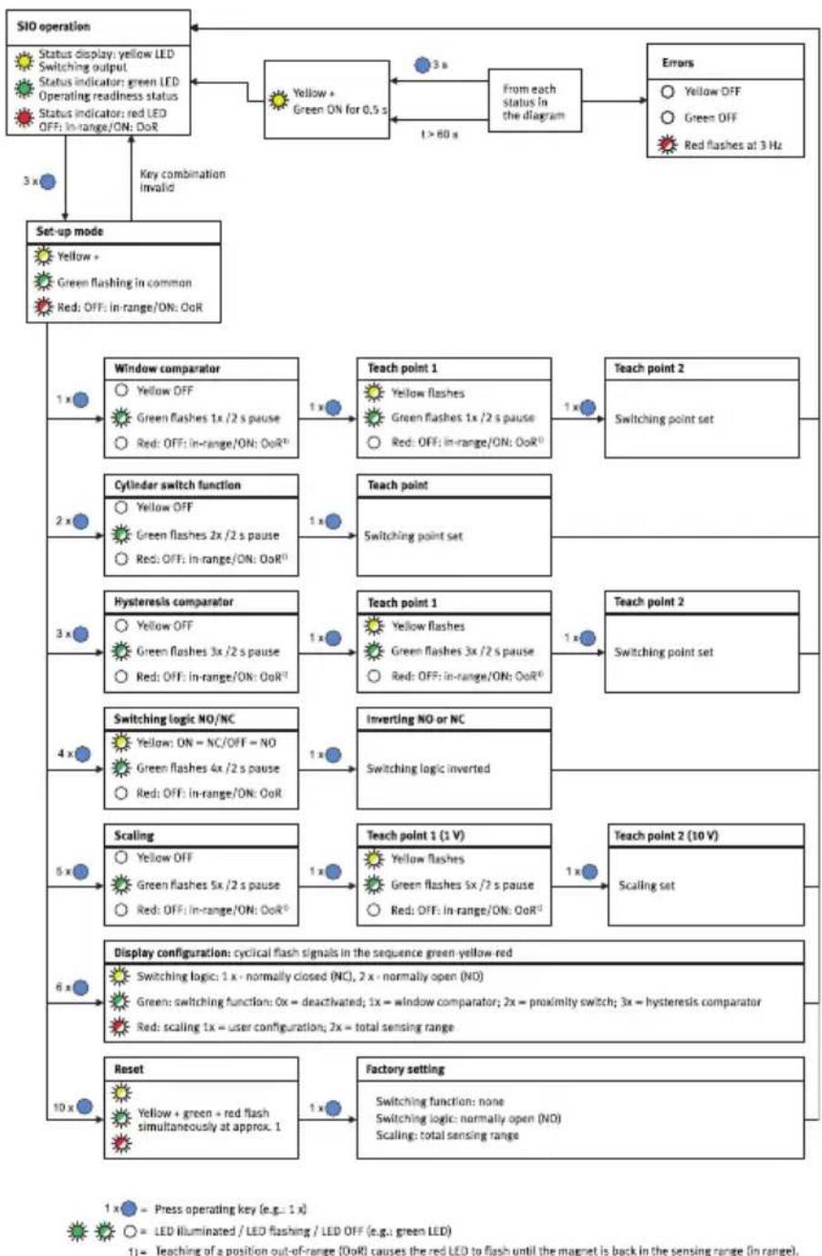
flowchart
graph TD
    A["SIO operation"] --> B["Status display: yellow LED\nSwitching output\nStatus indicator: green LED\nOperating readiness status\nStatus indicator: red LED\nOFF: in-range/ON: DoR"]
    B --> C{Yellow + Green ON for 0.5 s}
    C -->|1 > 60 s| D["From each status in the diagram"]
    D --> E["Errors"]
    E --> F["Yellow OFF\nGreen OFF\nRed flashes at 3 Hz"]
    C --> G["Set-up mode"]
    G --> H["Yellow + Green flashing in common\nRed: OFF: in-range/ON: OoR"]
    H --> I["Window comparator\nYellow OFF\nGreen flashes 1x /2 s pause\nRed: OFF: in-range/ON: OoR"]
    I --> J["Teach point 1\nYellow flashes\nGreen flashes 1x /2 s pause\nRed: OFF: in-range/ON: OoR"]
    J --> K["Teach point 2\nSwitching point set"]
    G --> L["Cylinder switch function\nYellow OFF\nGreen flashes 2x /2 s pause\nRed: OFF: in-range/ON: OoR"]
    L --> M["Teach point\nSwitching point set"]
    G --> N["Hysteresis comparator\nYellow OFF\nGreen flashes 3x /2 s pause\nRed: OFF: in-range/ON: OoR"]
    N --> O["Teach point 1\nYellow flashes\nGreen flashes 3x /2 s pause\nRed: OFF: in-range/ON: OoR"]
    O --> P["Teach point 2\nSwitching point set"]
    G --> Q["Switching logic NO/NC\nYellow: ON = NC/OFF = NO\nGreen flashes 4x /2 s pause\nRed: OFF: in-range/ON: OoR"]
    Q --> R["Inverting NO or NC\nSwitching logic inverted"]
    G --> S["Scaling\nYellow OFF\nGreen flashes 5x /2 s pause\nRed: OFF: in-range/ON: OoR"]
    S --> T["Teach point 1 (1 V)\nYellow flashes\nGreen flashes 5x /2 s pause\nRed: OFF: in-range/ON: OoR"]
    T --> U["Teach point 2 (10 V)\nScaling set"]
    G --> V["Display configuration: cyclical flash signals in the sequence green-yellow-red\nSwitching logic: 1 x - normally closed (NC), 2 x - normally open (NO)\nGreen: switching function: 0x - deactivated; 1x - window comparator; 2x - proximity switch; 3x - hysteresis comparator\nRed: scaling 1x = user configuration; 2x = total sensing range"]
    G --> W["Reset\nYellow + green + red flash simultaneously at approx. 1"]
    W --> X["Factory setting"]
    X --> Y["Switching function: none\nSwitching logic: normally open (NO)\nScaling: total sensing range"]
Fig. 13: Settings using the operating key (menu structure)
8 Malfunctions
8.1 Diagnostics via LED
| LED display Possible cause Remedy | ||||
| Yellow Green Red | ||||
[ZYWS]   All LEDs are off. All LEDs are off. | Fault in power supply. Connect power supply. | |||
| Fault in connecting cable. Replace connecting cable. | ||||
| Device is faulty. Replace device. | ||||
   Yellow LED is off.Green LED is off.Red LED is flashing. Yellow LED is off.Green LED is off.Red LED is flashing. | Hardware error. Switch power supply on/off.Replace device. | |||
   Yellow LED flashes at 3 Hz. Yellow LED flashes at 3 Hz. | Short circuit or overload at the switching output. | Eliminate short circuit or overload. | ||
| Parameter error. Reset device to factory setting→7.3 Reset position transmitter to factory setting. | ||||
  [SCXG]Yellow LED flashes at 3 HzGreen LED flashing at 1 Hz [SCXG]Yellow LED flashes at 3 HzGreen LED flashing at 1 Hz | Communication error in IO-Link mode. | Check IO-Link master.Restart communication.Check C/Q line. | ||
Tab. 7: LED displays in case of malfunctions
i
If the device detects an error during IO-Link operation, a status message is output at the IO-Link master. The IO-Link/switching output is not blocked.
8.2 General malfunctions
| Malfunction Cause Remedy | ||
| Incorrect or unexpected signals at the analogue output or with the IO-Link process data. | Drive is not suitable. | Use a suitable drive. |
| Device is faulty. Replace device. | ||
| No power supply or impermissible operating voltage. | Maintain operating voltage range. | |
| Short circuit or overload at the switching output. | Eliminate short circuit or overload. | |
| Incorrect or unexpected signals at the analogue output or with the IO-Link process data. | Magnetic object in the immediate vicinity of the position transmitter. | Do not place magnetic objects in the immediate vicinity of the position transmitter. |
| Sensor or drive was rotated 180° after initial commissioning. | Reset to factory setting using the operating key or via IO-Link. | |
| Incorrect or unexpected signals during initial commissioning on grippers or in attachments with ferromagnetic components. | On initial commissioning, move gripper jaws or piston within the sensing range, e.g. to both end positions. | |
| Switching output does not switch in accordance with the settings. | Short circuit or overload at the switching output. | Eliminate short circuit or overload. |
| Device is faulty. Replace device. | ||
| Settings cannot be edited. Access | protection is active. Unblock operating key (only possible via IO-Link). | |
Tab. 8: Possible malfunctions
9 Disassembly
- Switch off the power supply.
- Disconnect connections from the position transmitter.
- Unscrew the retaining screws → Fig. 8.
- Remove the position transmitter from the T-slot of the drive.
10 Technical data
10.1 General
| SDAT-MHS-... 50 80 100 125 160 | |||||
| Conformity | → www.festo.com/sp | ||||
| Note on materials | halogen-free | ||||
| Input signal/measuring element | |||||
| Sensing range ^1) [mm] | 50 | 80 | 100 | 125 | 160 |
| Signal processing | |||||
| Sampling interval typ. [ms] | 1 | ||||
| Max. traverse velocity [m/s] | 3 | ||||
| SDAT-MHS-... 50 80 100 125 160 | ||||||
| Output, general | ||||||
| Resolution of travel [mm] 0.05 | ||||||
| Switching output | ||||||
| Switching output PNP | ||||||
| Repetition accuracy of switching point [mm] 0.1 | ||||||
| Hysteresis [mm] ≤ 0.3 | ||||||
| Analogue output | ||||||
| Analogue output [V] 0 ... 10 | ||||||
| Sensitivity [mV/mm] 180 113 90 72 56 | ||||||
| Typical linearity error [mm] ±0.25 | ||||||
| Repetition accuracy [mm] 0.1 | ||||||
| Min. load resistance of voltage output [kΩ] | 20 | |||||
| Electronics | ||||||
| Operating voltage DC [V] 15 ... 30 | ||||||
| Typical signal running time [ms] | <2 | |||||
| Electromechanics | ||||||
| Cable length [m] | 0.3 | |||||
| Conductor nominal cross section [mm2] | 0.1 | |||||
| Mechanical system | ||||||
| Max. tightening torque [Nm] | 0.5 | |||||
| Information on materials – housing | PA-reinforced, polyester, high-alloy stainless steel, nickel-plated brass | |||||
| Immission/emission | ||||||
| Ambient temperature [°C] | -25 ... +70 | |||||
| Ambient temperature with flexible cable installation [°C] | -20 ... +70 | |||||
| Degree of protection (to EN 60529) IP65/IP68Condition with IP68: test duration 24 h | ||||||
1) Type-dependent
Tab. 9: Technical data SDAT-MHS
10.2 IO-Link
| SDAT-MHS-... 50 80 100 125 160 | |||||
| Protocol version Device V1.1 | |||||
| Profile Smart Sensor Profile | |||||
| Function classes 0x8000:Identification | 0x8001:Binary Data Channel0x8002:Process Data Variable0x8003:Diagnosis0x8004:Teach Channel | ||||
| Communication mode COM3 (230.4 kbaud) | |||||
| Process data length IN 2 byte | |||||
| Port class A, 4-pin | |||||
| Device ID 0x000010 0x000011 0x000012 0x000013 0x000014 | |||||
Tab. 10: Physical layer
| Process data record: 2 bytes | ||||||||||||||||
| Bit | 15 | 14 | 13 | 12 | 11 | 10 | 9 | 8 | 7 | 6 | 5 | 4 | 3 | 2 | 1 | 0 |
| Proces s data | Process Data Variable (PDV)→ Tab. 12 Range of values of the process data variables (PDV) for the device lengths → Process data with use of IODD | BDC4 ^1) | BDC3 ^1) | BDC2 ^1) | BDC1 ^1) | |||||||||||
| Data Position | switch 4 | switch 3 | switch 2 | switch 1 | ||||||||||||
| Type | Unsigned Integer | Boolean | ||||||||||||||
1) BDC = binary data channel (BinaryDataChannel)
Tab. 11: Process data content
Raw data
| Device length | Nominal sensing range [mm] | PDV min. OoR^1) | PDV minimum value of nominal sensing range | PDV maximum value of nominal sensing range | PDV max. OoR^2) | PDV OoR after Power ON^3) |
| M50 | 0 ... 50 | 0 | 21 | 1044 | 1064 | 4095 |
| M80 | 0 ... 80 | 0 | 21 | 1659 | 1679 | 4095 |
| M100 | 0 ... 100 | 0 | 21 | 2068 | 2088 | 4095 |
| M125 0 ... 125 | 0 21 2580 260 | 0 4095 | ||||
| M160 0 ... 160 | 0 21 3297 331 | 7 4095 |
1) Min OoR (out of range): minimum value of the sensing range
2) Max OoR (out of range): maximum value of the sensing range
3) OoR after Power ON: outside the sensing range when operating voltage is applied
Tab. 12: Range of values of the process data variables (PDV) for the device lengths
Process data with use of IODD
| Device length | Nominal sensing range [mm] | PDV min. OoR^1) | PDV minimum value of nominal sensing range | PDV maximum value of nominal sensing range | PDV max. OoR^2) | PDV OoR after Power ON^3) |
| M50 0 ... 50 0 | 103 5099 5196 | 19999 | ||||
| M80 0 ... 80 0 | 103 8102 8200 | 19999 | ||||
| M100 0 ... 100 | 0 103 10100 | 10198 19999 | ||||
| M125 0 ... 125 | 0 103 12600 | 12698 19999 | ||||
| M160 0 ... 160 | 0 103 16102 | 16200 19999 |
1) Min OoR (out of range): minimum value of the sensing range
2) Max OoR (out of range): maximum value of the sensing range
3) OoR after Power ON: outside the sensing range when operating voltage is applied
Tab. 13: Range of values of the process data variables with use of IODD for the device lengths
| Index Su | bin de x | Name | Default value (example M50) | Access^1) | Length | Format | ||
| U | M S | |||||||
| 0x0002 0 | System Com- mand | →Tab. 15 System commands | — | W | W | 1 byte Unsigned Integer | ||
| 0x000C | 0 | Device Access Locks ^2) | 0 = unlocked1 = locked | R | R/W | R/W | 2 byte Record | |
| 0x0010 | 0 | Vendor Name | Festo SE & Co. KG | R | R | R | 64 byte | String |
| 0x0011 | 0 | Vendor Text | http://www.festo.com | R | R | R | 64 byte | String |
| 0x0012 | 0 | Product Name | SDAT-MHSM50-1L-SA-E-0.3-M8 | R | R | R | 64 byte | String |
| 0x0013 | 0 | Product ID ^3) | 1531265 | R | R | R | 64 byte | String |
Technical data
| Index Su | bin de x | Name Default value (example M50) | Access ^1) | Length Format | ||
| U M | S | |||||
| 0x0014 0 | Product Text Position | transmitter | R R R | 64 byte String | ||
| 0x0015 0 | Serial-Number | 12345678901 R R R | 16 byte | String | ||
| 0x0016 0 | Hardware Revision | REVxy R R R 64 byte | String | |||
| 0x0017 0 | Firmware Revision | REVxy R R R 64 byte | String | |||
| 0x0018 0 | Application Specific Tag ^4) | *** R/ | W | R/W | R/W | 32 byte String |
| 0x0028 0 | Process Data Input | →Tab. 11 Process data content | R R R | 2 byte | Record | |
1) Authorisation group U = user, M = maintenance, S = specialist; access W = write, R = read, R/W = read and write, - = no access
2) Bit 0: lock parameter write access; Bit1: lock data storage; Bit3: lock local user interface (operating key)
3) Festo part number
4) Value defined by user
Tab. 14: Service data
| Value | Access^1)2) | Length | Format | Format | ||
| U | M | S | ||||
| 128 | — | — | W | 1 byte | Unsigned Integer | Reset Device |
| 130 | — | — | W | Restore Factory Settings | ||
| 176 | — | — | W | Reset Warnings | ||
| 160 | — | W | W | Teach SP1 BDC1 ^3) | ||
| 161 | — | W | W | Teach SP2 BDC1 ^3) | ||
| 162 | — | W | W | Teach SP1 BDC2 ^3) | ||
| 163 | — | W | W | Teach SP2 BDC2 ^3) | ||
| 164 | — | W | W | Teach SP1 BDC3 ^3) | ||
| 165 | — | W | W | Teach SP2 BDC3 ^3) | ||
| 166 | — | W | W | Teach SP1 BDC4 ^3) | ||
| 167 | — | W | W | Teach SP2 BDC4 ^3) | ||
| Value Access 1)2) | Length Format Format | |||||
| 168 — W | W 1 byte | Unsigned | Integer Teach | ch Scale | Start analogue | output |
| 169 — W | W Teach | Scale End | analogue | output | ||
1) Authorisation group U = user, M = maintenance, S = specialist; access W = write, - = no access
2) If access = write, an attempted read access will return error code 0x8101.
3) Access also possible via the standard function class 0x8004 "Teach Channel" of the Smart Sensor Profile.
Tab. 15: System commands
| Index Sub- | index | Name Default | value (example M50)1) | Access2) | Length | Format3) | ||
| U | M | S | ||||||
| BDC1 | ||||||||
| 0x003C | 1 | Setpoint SP1 | 175 | R | R/W | R/W | 2 byte | Unsigned Integer |
| 2 | Setpoint SP2 | 250 | 2 byte | |||||
| 0x003D | 1 | Switchpoint logic | 0 | 1 byte | ||||
| 2 | Switchpoint mode | 0 | 1 byte | |||||
| 3 | Switchpoint hysteresis | 5 | 2 byte | |||||
| BDC2 | ||||||||
| 0x003E | 1 | Setpoint SP1 | 275 | R | R/W | R/W | 2 byte | Unsigned Integer |
| 2 | Setpoint SP2 | 350 | 1 byte | 2 byte | ||||
| 0x003F 1 | Switchpoint logic 0 | |||||||
| 2 | Switchpoint mode | 0 | 1 byte | |||||
| 3 | Switchpoint hysteresis | 5 | 2 byte | |||||
| Analogue current output | ||||||||
| 0x3000 | 1 | Scale Start | 1 | R | R/W | R/W | 2 byte | Unsigned Integer |
| 2 | Scale End | 1063 | 2 byte | |||||
| PDV 0: normal, 1: inverted, not for analogue current output | ||||||||
| 0x3010 | 0 | PDV Invertierung | 0 | R | R/W | R/W | 1 byte | Unsigned Integer |
| BDC3 | ||||||||
| Index Sub- | index | Name Default | value (example M50) ^1) | Access ^2) | Length Format | 3) | ||
| U M S | ||||||||
| 0x4000 1 Setpoint SP1 375 R R/W R/W 2 byte Unsigned | 1 byte | 1 byte | Integer | |||||
| 2 Setpoint SP2 450 2 byte | ||||||||
| 0x4001 1 Switchpoint logic 0 | ||||||||
| 2 Switchpoint mode 0 | ||||||||
| 3 Switchpoint hysteresis | 5 | 2 byte | ||||||
| BDC4 | ||||||||
| 0x4002 1 Setpoint SP1 475 R R/W R/W 2 byte Unsigned | 1 byte | 1 byte | Integer | |||||
| 2 Setpoint SP2 550 2 byte | ||||||||
| 0x4003 1 Switchpoint logic 0 | ||||||||
| 2 Switchpoint mode 0 | ||||||||
| 3 Switchpoint hysteresis | 5 | 2 byte | ||||||
1) Raw data without use of IODD
2) Authorisation group U = user, M = maintenance, S = specialist; access R = read, R/W = read and write
3) Coding BDC1... BDC4 → Tab. Tab. Coding switching point parameters
Tab. 16: parameter
| Name | Coding |
| Setpoint SP1/SP2 ^1) | 12 bit position values |
| Switchpoint logic | 0 = output signal not inverted; 1 = output signal inverted |
| Switchpoint mode | 0 = deactivated; 1 = proximity switch, 2 = window comparator, 3 = hysteresis comparator |
| Switchpoint hysteresis | Fix: 5 |
1) Value range → Tab. Value range of the process data variables (PDV) for the device lengths
Tab. 17: Coding switch point parameter
| Error code | Mode | Type | Comments |
| 0x4000 | (Dis)appear | Error | Temperature fault |
| 0x5000 | (Dis)appear | Error | Hardware defective |
| 0x5111 | (Dis)appear | Warning | Voltage too low |
| 0x6320 | (Dis)appear | Error | Parameter error |
| Error code Mode Type | Comments | ||
| 0x8CA0 (Dis)appear | Error Magnetic field too | weak, unsuit- | able drive |
| 0xFF91 (Dis)appear | Notification Data Storage | upload request |
Tab. 18: Error Codes
10.3 I-Port
The IO-Link specification data generally apply 10.2 IO-Link.
For information on the process data contents Tab. 11 Process data content.
| Index Name | Default value Access | 1) | Length | |
| 0x0040 | Device attributes | 0x00 | R/W | 1 byte |
| 0x0041 | Extended parameters | 0x0000 | R/W | 2 byte |
| 0x0042 | Diagnosis parameter | 0x0000 | R | 2 byte |
| 0x0043 | Device specific parameters | →Tab. 20 Device-specific parameters | R/W | 8 byte |
| 0x00FE | I-Port Revision | 0x0101 | R/W | 2 byte |
1) Access R = read, R/W = read and write
Tab. 19: Additionally supported parameters in accordance with I-Port specification
| Byte | 1 | 2 | 3 | 4 | 5 | 6 | 7 | 8 |
| IO-Link index | 0x003C | 0x003D | ||||||
| Subindex | 1 | 2 | 1 | 2 | 3 | |||
| Function ^1) | SP1 | SP2 | Logic | Mode HY | ||||
| Byte | high | low | high | low | — | — | high | low |
| Default value | 0x00 | 0xAF | 0x00 | 0xFA | 0x00 | 0x00 | 0x00 | 0x05 |
1) Coding parameter Tab. Coding switching point parameters
Tab. 20: Device-specific parameters
10.4 Technical data for UL/CSA certification
Electrical and environmental ratings UL/CSA
| Input Voltage | Max. 30 V DC, Class 2 |
| Input current | 160 mA/max. 4.8 W |
| Analog output | 0 ... 10 V |
| Transistor output | Max. 30 V DC, 100 mA G.P. |
| Electrical and environmental ratings UL/CSA | |
| Maximum Ambient Temperature 70 °C/158 °F | |
| NEMA enclosure type number (Enclosure Type Rating) | Type 1 |
Tab. 21: Electrical data and ambient conditions UL/CSA
Copyright:
Festo SE & Co. KG
73734 Esslingen
Ruiter Straße 82
Deutschland
Phone:
+49 711 347-0
Internet:
- FESTO
- Table of contents
- About this document.... 4
- Safety....4
- Additional information....5
- Product overview.... 5
- Mounting....11
- Commissioning 13
- Operation.... 18
- Malfunctions....22
- Disassembly.... 23
- Technical data....23
- About this document
- Applicable Documents
- Safety
- General safety instructions
- Intended use
- Training of qualified personnel
- UL/CSA certification
- Product overview
- Additional information
- Product overview
- Design
- Function
- Analogue output
- Scaling of the analogue signal
- Switching functions and switching logic
- Window comparator
- Teach-in point
- Switching logic
- Switching output operating mode (SIO)
- IO-Link operating mode
- Mounting
- Mounting
- Electrical installation
- WARNING
- Risk of injury due to electric shock.
- Mechanical installation
- Commissioning
- Switch on the position transmitter
- Setting Set-up mode
- Program switching output
- Set window comparator
- Commissioning
- Adjusting proximity switch
- Teach point
- Set hysteresis comparator
- Inverting switching logic
- Block/unblock operating key
- LED display with blocked operating key
- Programming IO-Link output
- Operation
- Magnetic direction detection and magnetic direction correction
- LED displays in normal operation
- Query configuration
- Reset position transmitter to factory setting
- Analogue output and switching function operation
- Malfunctions
- Diagnostics via LED
- General malfunctions
- Disassembly
- Technical data
- General
- Technical data
- I-Port
- Technical data for UL/CSA certification
Brand : Festo
Model : SDAT-MHS-M100-1L-SV-E-0.3-M8
Category : Uncategorized