
CPV14-VI-P2-1/8-D - Control Festo - Free user manual and instructions
Find the device manual for free CPV14-VI-P2-1/8-D Festo in PDF.


| Product Type | Multiple Connector Plate for CPV Valve Terminal |
| Manufacturer | Festo |
| Model | CPV14-VI-P2-1/8-D |
| Category | Valve Terminal Accessory |
| Protection Class | IP65 |
| Number of Valve Positions | 2 (P2 variant) |
| Mounting Cut-out Dimensions (A x B) | 42.6 mm x 30.5 mm |
| Mounting Cut-out Dimensions (C x D) | 55.6 mm x 12 mm |
| Number of Screws | 4 |
| Screw Size | M5 (DIN EN ISO 4762) |
| Screw Material | Corrosion Resistant |
| Tightening Torque | 5 Nm ±10% |
| Screw Depth | 7.5 mm to 9.5 mm |
| Seals Included | Yes (3 and 4-part seals) |
| Sealing Surface Requirement | Flat, free of marks and scratches |
| Compatible Models | CPV14-VI-P...-D with multiple connector plate |
| Application | Pneumatic valve terminal connection |
| Assembly Note | Observe pneumatic section assembly instructions |
Frequently Asked Questions - CPV14-VI-P2-1/8-D Festo
User questions about CPV14-VI-P2-1/8-D Festo
0 question about this device. Answer the ones you know or ask your own.
Ask a new question about this device
Download the instructions for your Control in PDF format for free! Find your manual CPV14-VI-P2-1/8-D - Festo and take your electronic device back in hand. On this page are published all the documents necessary for the use of your device. CPV14-VI-P2-1/8-D by Festo.
USER MANUAL CPV14-VI-P2-1/8-D Festo
natural_image
Isometric line drawing of a multi-tiered electrical connector with terminal blocks and connectors (no text or symbols)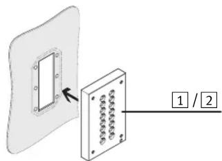
![Diagram showing a component assembly with pins and a labeled section [1]/[2] indicating a pin configuration or assembly.](/content/2026/05/855080/images/f80baefbe568daaf868367a9909921270ba9fb6b579cef8395b3149a05939713.jpg)
$$ l - t = 7, 5 \mathrm{mm} \dots 9, 5 \mathrm{mm} $$
$$ 5 \mathrm{Nm} \pm 10\% $$
natural_image
Technical illustration of a mechanical assembly with pins and a housing (no text or symbols)2. Preparing for assembly
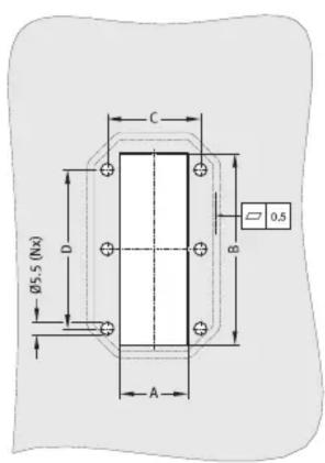


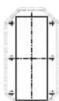
- Note the dimensions of the cut-out for fitting ( Table).
In order to comply with protection class IP65: - Make sure that the surface near the sealing surface:
- is flat.
- is free of marks and scratches.
Mounting cut-out for
CPV14-VI-P...-D 1
| Type | A ± 0.1 | B ± 0.1 | C ± 0.1 | D ± 0.1 | N |
| CPV14-VI-P...-D 1 | |||||
| P2 | 42.6 | 30.5 | 55.6 | 12 | 4 |
| P4 | 42.6 | 58.5 | 55.6 | 40 | 6 |
| P6 | 42.6 | 86.5 | 55.6 | 68 | 6 |
| P8 | 42.6 | 114.5 | 55.6 | 96 | 6 |
3. Assembly
natural_image
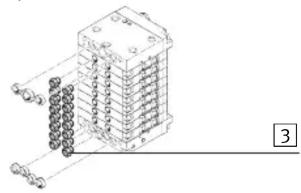
Isometric line drawing of a multi-tiered electrical connector with terminal blocks (no text or symbols)- Press the seals 3 supplied into the holes in the CPV valve terminal.
- Note that the 3 and 4-part seals supplied with the end plates of the CPV valve terminal are only required with multiple connector plate [2].
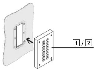
- Position multiple connector plate 1 or 2 in the mounting cut-out from inside.
$$ l - t = 7. 5 \mathrm{mm} \dots 9. 5 \mathrm{mm} $$
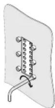
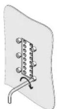
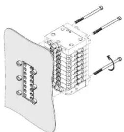
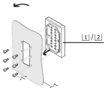
- Fasten the multiple connector plate 1 or 2 with corrosion resistant N x M5 screws as per DIN EN ISO 4762.
- Select the screw length l as follows. A screw depth of at least 7.5 mm to max. 9.5 mm must be guaranteed.
- Tighten the screws. Maintain the permitted tightening torque.
natural_image
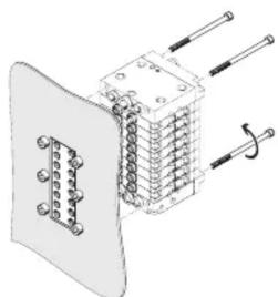
Technical illustration of a mechanical or electrical component with pins and wires (no text or symbols)For mounting the valve terminal:
- Observe the assembly instructions for the pneumatic section of the valve terminal.
Brand : Festo
Model : CPV14-VI-P2-1/8-D
Category : Control