
SFAB-600U-HQ10-PNLK-PNVBA-M12 - Meter Festo - Free user manual and instructions
Find the device manual for free SFAB-600U-HQ10-PNLK-PNVBA-M12 Festo in PDF.


| Product Type | Flow sensor (thermal mass flow meter) |
| Model | SFAB-600U-HQ10-PNLK-PNVBA-M12 |
| Measurement Principle | Thermal heat loss |
| Measured Variables | Volumetric flow rate, mass flow rate, temperature, volume |
| Flow Measuring Range (Air) | 6 … 600 l/min |
| Temperature Measuring Range | 0 … 50 °C |
| Operating Pressure | 0 … 10 bar (0 … 1 MPa) |
| Supply Voltage | 15 … 30 V DC |
| Power Consumption | ≤ 90 mA (at 24 V DC) |
| Switching Outputs | 2 x PNP or NPN (switchable), max. 100 mA each |
| Analogue Output | 0…10 V, 1…5 V, or 4…20 mA (selectable) |
| Communication Interface | IO-Link V1.1, COM3, process data 64 bit |
| Display | LCD with backlight, rotatable in 90° steps |
| Electrical Connection | M12x1, 5-pin, A-coded |
| Pneumatic Connection | G1/4 (or similar, not specified) - two ports |
| Mounting | H-rail (DIN), wall mounting (adapter plate), or panel mounting |
| Degree of Protection | IP65 |
| Ambient Temperature | 0 … 50 °C |
| Medium | Compressed air, nitrogen, argon, carbon dioxide |
| Housing Material | PA-reinforced |
| Dimensions (approx.) | Height: ~120 mm, Width: ~50 mm, Depth: ~70 mm (estimated) |
| Weight | Approx. 0.3 kg (estimated) |
| Standards | RCM marked, CE compliant |
Frequently Asked Questions - SFAB-600U-HQ10-PNLK-PNVBA-M12 Festo
User questions about SFAB-600U-HQ10-PNLK-PNVBA-M12 Festo
0 question about this device. Answer the ones you know or ask your own.
Ask a new question about this device
Download the instructions for your Meter in PDF format for free! Find your manual SFAB-600U-HQ10-PNLK-PNVBA-M12 - Festo and take your electronic device back in hand. On this page are published all the documents necessary for the use of your device. SFAB-600U-HQ10-PNLK-PNVBA-M12 by Festo.
USER MANUAL SFAB-600U-HQ10-PNLK-PNVBA-M12 Festo
natural_image
Technical line drawing of a mechanical device with ports and a central dial (no text or symbols)FESTO
Operating instruction
Translation of the original instructions
IO-Link ^® is a registered trademark of its respective trademark holder in certain countries.
Table of contents
1 Applicable Documents....5
2 Safety....5
2.1 Safety instructions....5
2.2 Intended use.... 5
2.3 Training of qualified personnel....5
3 Additional information....5
4 Product overview.... 6
4.1 Structure....6
4.1.1 Product design....6
4.1.2 Display components....7
4.2 Function....9
4.2.1 Functional principle....9
4.2.2 Operating statuses.... 10
4.2.3 Switching outputs.... 11
4.2.4 Filter.... 12
4.2.5 Analogue output.... 13
4.2.6 Security code....13
4.2.7 Minimum value and maximum value....13
4.2.8 Replication of the parameters.... 13
4.2.9 Switchover of standard condition.... 14
4.2.10 Zero point synchronisation.... 14
5 Mounting....14
5.1 Mounting the sensor on the H-rail.... 15
5.2 Mounting the sensor with wall mounting.... 15
5.3 Mounting the sensor on the plate.... 16
5.4 Rotating the display.... 16
6 Installation.... 16
6.1 Installation, pneumatic.... 16
6.2 Installation, electrical.... 17
7 Commissioning....17
7.1 Switching on the sensor in RUN mode.... 17
7.2 Displaying parameters in SHOW mode.... 18
7.3 Configuring the sensor in EDIT mode.... 20
7.3.1 Starting EDIT Mode 20
7.3.2 Configuring the switching output.... 21
7.3.3 Changing the device settings....21
7.3.4 Setting the volume pulse output.... 21
7.3.5 Setting the analogue output.... 21
7.3.6 Replicating parameters 22
7.3.7 Zero point synchronisation....22
7.4 Teaching the switching points in TEACH mode.... 24
7.5 Measuring volume manually in RECORDER mode.... 24
8 IO-Link interface description.... 25
8.1 General information, IO-Link.... 25
8.2 Identification parameters.... 26
8.3 IO-Link default parameters....27
8.4 IO-Link system commands.... 28
8.5 Smart sensor profile parameters.... 29
8.6 Device-specific parameters.... 34
8.7 IO-Link teach-in.... 38
8.8 Block parameterisation.... 39
8.9 Process data IN.... 41
8.10 Diagnostics IO-Link.... 41
9 Operation.... 42
9.1 Reset sensor to factory setting....42
10 Cleaning.... 42
11 Fault clearance.... 43
12 Dismantling.... 43
13 Technical data....44
13.1 Examples for calculating the maximum error of the display.... 48
1 Applicable Documents
[NO TEXT]
All available documents for the product→ www.festo.com/sp.
2 Safety
2.1 Safety instructions
- Only use the product in its original condition without unauthorised modifications.
-Only use the product if it is in perfect technical condition. - Observe the identifications on the product.
- Condensation, oil mist, foreign matter and other contaminants in the compressed air can damage the product. Only use media in accordance with the specifications 13 Technical data.
- The product may generate high frequency interference, which may require interference suppression measures in residential areas.
2.2 Intended use
The flow sensor monitors the flow rate, volume and temperature of gaseous media in piping systems or terminals in industry.
2.3 Training of qualified personnel
Work on the product may only be carried out by qualified personnel who can evaluate the work and detect dangers. The qualified personnel have skills and experience in dealing with electropneumatic (open-loop) control technology.
3 Additional information
-Contact the regional Festo contact if you have technical problems www.festo.com.
-Accessories → www.festo.com/catalogue.
4 Product overview
4.1 Structure
4.1.1 Product design
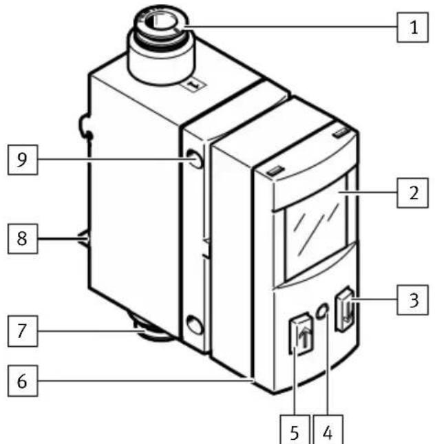
Fig. 1: Control elements and connection elements
1 Pneumatic connection 1
2 Display
3 Pushbutton [B]
4 [Edit] key
5 Pushbutton [A]
6 Plug for the electrical connection M12
7 Pneumatic connection 2
8 Mounting slide for H-rail mounting and wall mounting, on the back
9 Hole for panel mounting
4.1.2 Display components
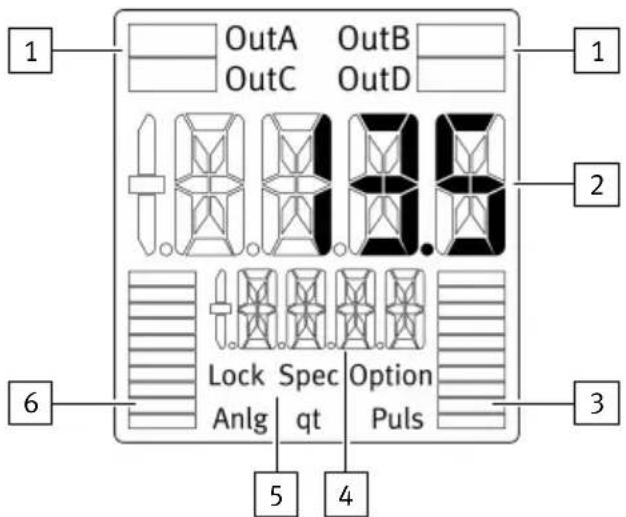
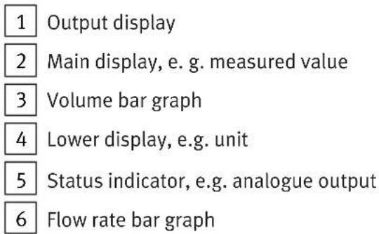
Fig. 2: LCD display
Symbols on the display
| Example for LCD display | Meaning | |
| Output display | ||
| ‘OutA’ Switching output OutA selected, flashes when IO-Link is active. | ||
 | ‘OutA’ Switching output OutA set. | |
| ‘OutC’ Volume pulse OutC selected, flashes when IO-Link is active. | ||
 | ‘OutC’ Volume pulse OutC set. | |
| ‘OutB’ Switching output OutB selected. | ||
 | witching output OutB set. | |
| ‘Pulse’ Volume pulse selected. | ||
 | alogue output selected. | |
| ion/input display | ||
| [CGX4] | Graphic display of flow measurement | |
| [2HGD] | Graphic display of volume measurement | |
| ‘q’ Input signal flow rate selected. | ||
| ‘t’ Input signal temperature selected. | ||
| ‘Lock’ Security code activated. | ||
| ‘Spec’ Special menu selected. | ||
| ‘Option’ Illuminates when parameters having a special influence on the measured value indicator have been changed compared to the factory setting: reference condition (standard), gas. | ||
Tab. 1: Symbols on the display
| Example for LCD display Meaning | ||
| Main display Lower | display | |
| Measured value indicator and unit in RUN mode | ||
| ‘17.3’ ‘l/min’ Measured value indicator and unit | ||
| Menu for the switching outputs OutA, OutB, OutC | ||
| ‘Edit’ ‘Flow’ Edit menu for the switching outputs | ||
| ‘OFF’ ‘Fctn’ Switching function deactivated. | ||
| _I-‘Fctn’ Threshold value comparator | ||
| _I^-I_‘Fctn’ Window comparator | ||
| _[]^- | ‘Fctn’ 2-point threshold value comparator | |
| ‘18.0’ ‘SP’ Switching point value | ||
| ‘8.0’ | ‘SP.Lo’ | Value of lower switching point |
| ‘12.2’ ‘SP.Hi’ | Value of upper switching point | |
| ‘2.8’ | ‘HY’ | Hysteresis value |
| ‘N/O’ ‘logic’ | Switching characteristics of the switching outputs:‘NO’ = N/O contact, normally open‘NC’ = N/C contact, normally closed | |
| ‘bLUE’ | ‘COLR’ Display colour | |
| ‘200’ ‘PULS’ / ‘MSEC’ Width of the volume pulse or mass pulse | ||
| Menu for the analogue output | ||
| ‘1_5V’ | ‘Out’ | Analogue output type ‘0_10V’, ‘1_5V’, ‘4_20MA’ |
| ‘38’ | ‘In.Hi’/‘%’ | Scaling of the analogue output: end value |
| ‘3’ | ‘In.Lo’/‘%’ | Scaling of the analogue output: start value |
| Menu for extreme values and mean values (SHOW menu) | ||
| ‘5.1’ ‘MIN’/‘l/Min’ | Minimum measured flow rate since switch-on or the last reset | |
| ‘30.8’ ‘MAX’/‘l/Min’ | Maximum measured flow rate since switch-on or the last reset | |
| ‘20.8’ ‘AVER’/‘l/Min’ | Average of the flow rate measurement, filter time constants switchable | |
| Menu for device settings (SPEC menu) | ||
| ‘64’ ‘Filt’ / ‘MSEC’ | Value of the filter time constant for the flow rate measurement signal | |
| ‘l/min’ ‘FLOW’ / ‘Unit’ | Display unit for flow rate measurement | |
| ‘0°C’ ‘REF’ / ‘Cond’ | Reference standard for gas volume | |
| ‘Air’ ‘GAS’ | Selection of the operating medium | |
| ‘OFF’ | ‘Z.Adj’ | Activation of the zero point synchronisation |
| ‘°C’ | ‘tEMP’/‘Unit’ | Display unit for temperature measurement |
| ‘Unit’ | ‘Sub.d’ | Settings of sub-display in RUN mode |
| ‘10’ ‘Eco’ / ‘SEC’ | Economy mode: period of time after which the display background lighting is switched off. | |
| ‘PNP’ | ‘bin’/‘Out’ | Switchover of the switching outputs between PNP and NPN |
| ‘FLOW’ | ‘bin’/‘Pin4’ | Switchover of the switching signal at pin 4 between flow monitoring and volume pulse |
| ‘FLOW’ | ‘bin’/‘Pin2’ | Switchover of the signal at Pin2 between flow monitoring, flow measurement and temperature recording |
| ‘OFF’ | ‘Lock’/‘Code’ Activation and specification of the security code | |
| ‘OFF’ | ‘MASt’ Activation of the IO-Link master function for replication of parameters | |
Tab. 2: Example for LCD display
4.2 Function
4.2.1 Functional principle
The sensor measures the standard flow rate or mass flow rate with the help of a thermal procedure. The sensor measures the amount of heat that is drawn from the heated surface of a micro-mechanical sensor element by the medium flowing past. The sensor determines the flow rate or the accumulated volume from the amount of heat removed and shows this on the display. The sensor calculates the temperature of the medium from the sensor signals. The sensor is connected to higher-level
Product overview
systems via switching outputs, a volume switching pulse, an analogue output or an IO-Link interface. Depending on the configuration, the switching outputs monitor a threshold value or a signal range. The outputs can be set as PNP or NPN and normally open (NO) or normally closed (NC). The analogue output can be operated either as a voltage output or as a current output. Through the IO-Link interface, process values can be read out and parameters changed and transmitted to additional devices. If the flow rate is integrated, a volume signal or mass signal can be calculated and output via a pulse output and an accumulated measured value via IO-Link.
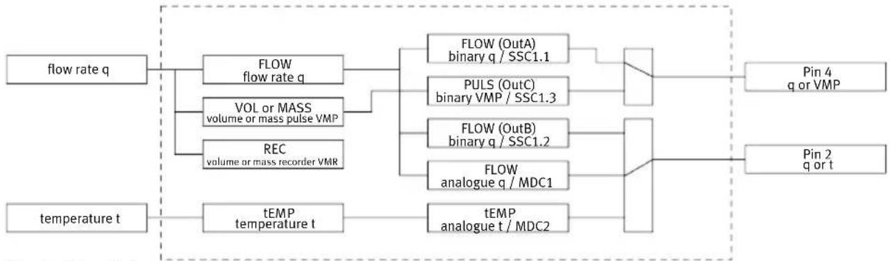
flowchart
graph LR
    A["flow rate q"] --> B["FLOW flow rate q"]
    A --> C["VOL or MASS volume or mass pulse VMP"]
    A --> D["REC volume or mass recorder VMR"]
    E["temperature t"] --> F["tEMP temperature t"]
    B --> G["FLOW (OutA) binary q / SSC1.1"]
    B --> H["PULS (OutC) binary VMP / SSC1.3"]
    B --> I["FLOW (OutB) binary q / SSC1.2"]
    B --> J["FLOW analogue q / MDC1"]
    G --> K["Pin 4 q or VMP"]
    H --> K
    I --> L["Pin 2 q or t"]
    J --> L
    F --> M["tEMP analogue t / MDC2"]
Fig. 3: Signal structure SFAB
4.2.2 Operating statuses
Operating status Function
| RUN mode | - Basic state after the operating voltage has been applied. - Display of the current measured value. - Display of the selected inputs and outputs. - Switchover between the measured variables of flow rate, volume and temperature. |
| SHOW mode | - Display of the current settings for the switching outputs and the analogue output. - Display and reset of the minimum and maximum values. - Display of the average flow rate measurement. |
| EDIT mode | - Setting or modification of parameters. |
| TEACH mode | - Acceptance of the current measured value to specify switching points. |
| RECORDER mode | - Manual measurement of the accumulated volume. |
Tab. 3: Operating statuses SFAB
4.2.3 Switching outputs
4.2.3.1 Switching functions
Threshold value comparator
| Function N/O (normally open) N/C (normally closed) | ||
| Switching function:- 1 switching point (SP) | 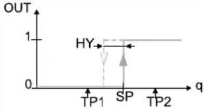 | 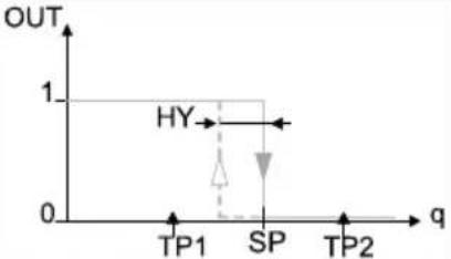 |
| TEACH mode:- 2 teach points (TP1, TP2)- SP = 12 (TP1 + TP2) | ||
Tab. 4: Threshold value comparator
Window comparator
| Function N/O (normally open) N/C (normally closed) | ||
| Switching function:- 2 switching points (SP.Lo, SP.Hi) | 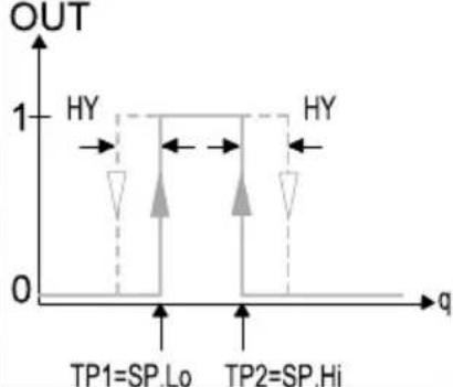 | 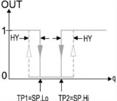 |
| TEACH mode:1)- 2 teach points (TP1, TP2)- TP1 = SP.Lo, TP2 = SP.Hi | ||
1) SP.Lo = smaller value, SP.Hi = larger value, independent of the teach sequence
Tab. 5: Window comparator
2-point threshold value comparator
| Function N/O (normally open) N/C (normally closed) | ||
| Switching function:- 2 switching points (SP.Lo, SP.Hi) | 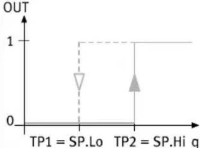 | 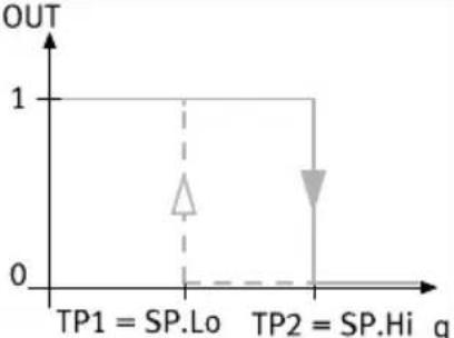 |
| TEACH mode:1)- 2 teach points (TP1, TP2)- TP1 = SP.Lo, TP2 = SP.Hi | ||
1) SP.Lo = smaller value, SP.Hi = larger value, independent of the teach sequence
Tab. 6: 2-point threshold value comparator
4.2.3.2 Colour change
A red colour change can be set in the display for the switching outputs OutA and OutB dependent on the switching status. The colour change enables the system status to be identified from a distance. The red display is always dominant.
| Parameter Meaning | |
| ‘bLUE’ The display is always blue; the colour change function is switched off. | |
| ‘R.On’ The display is red when the switching output is set (high = 1).The display is blue when the switching output is not set (low = 0). | |
| ‘R.OFF’ The display is red when the switching output is not set (low = 0).The display is blue when the switching output is set (high = 1). | |
Tab. 7: Change in colour of display
4.2.3.3 Volume measurement and mass measurement
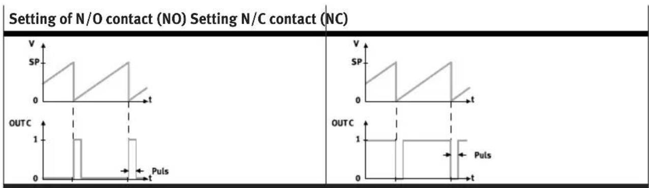
A threshold value for the volume or the mass is set in the accumulated volume measurement or mass measurement. If the configured threshold value is reached, the SFAB outputs a switching pulse at the switching output OutC. The volume measurement or mass measurement is restarted at every switching pulse. The pulse width is adjustable.
line
| Contact Type | Time (t) | Output Current (Puls) | | ------------ | -------- | --------------------- | | N/O contact | 0 | 0 | | N/O contact | 1 | 1 | | N/O contact | 2 | 0.5 | | N/O contact | 3 | 0 | | N/C contact | 0 | 0 | | N/C contact | 1 | 1 | | N/C contact | 2 | 0.5 | | N/C contact | 3 | 0 | | N/C contact | 4 | 0 |Tab. 8: Volume pulse with accumulated volume measurement
4.2.4 Filter
The filter smoothes the flow rate measurement signal in 12 stages. Smoothing affects all outputs. The switching times of the flow-related switching outputs and the rise time and fall time of the analogue output change. The filter time equals the time constant T of a low-pass filter.
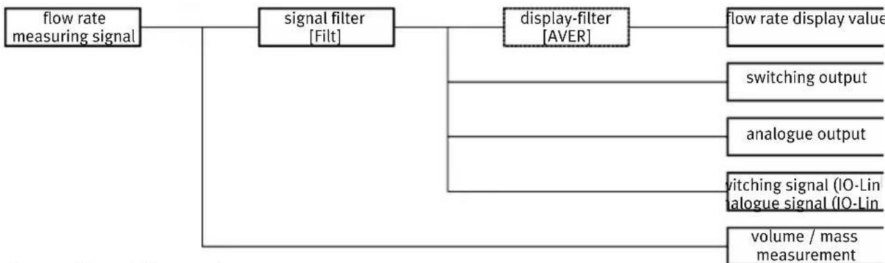
flowchart
graph TD
    A["flow rate measuring signal"] --> B["signal filter [Filt"]]
    B --> C["display-filter [AVER"]]
    C --> D["flow rate display value"]
    B --> E["switching output"]
    B --> F["analogue output"]
    B --> G["vitching signal (IO-Lin dialogue signal (IO-Lin)"]
    B --> H["volume / mass measurement"]
Fig. 4: Effect of filter settings
The display filter only affects the flow rate measured value in SHOW mode [AVER].
4.2.5 Analogue output
Analogue signal
The signal of the analogue output can be assigned the physical measured variables of flow rate or temperature. The physical measured value of flow rate is configured as standard.
Output signal
The analogue output can be configured either as voltage output 0 ... 10 V oder 1 ... 5 V or as current output 4 ... 20 mA. By default the voltage output is set to 0 ... 10 V.
Scaling of the analogue signal
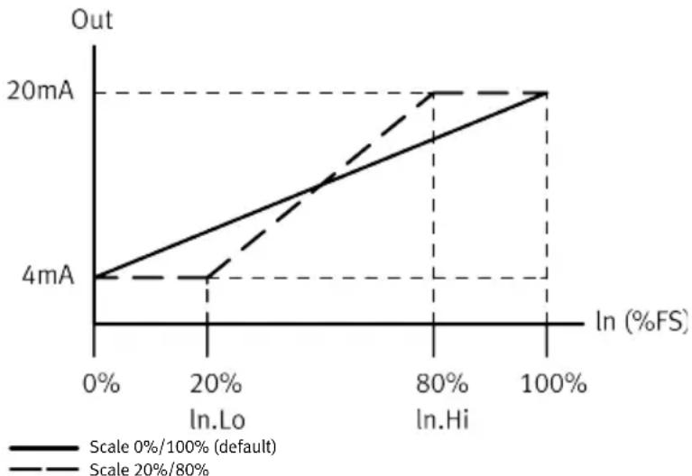
The default setting for the analogue output signal is 0 ... 10 V, 1 ... 5 V or 4 ... 20 mA for the complete sensing range "Full Scale (FS)". If only part of the sensing range is to be used, the analogue value output can be scaled to the partial range.
The analogue output can also be scaled in the negative range up to -100%FS.
line
| In (%FS) | Scale 0%/100% (default) (mA) | Scale 20%/80% (mA) | |---|---|---| | 0% | 4 | 4 | | 20% | ~6 | ~5.5 | | 80% | ~12 | ~18 | | 100% | ~18 | ~20 |Fig. 5: Example: scaling of the analogue signal at the current output
4.2.6 Security code
A 4-digit numeric code can be set to protect the device settings from unauthorised access. The security code must be entered in EDIT mode and TEACH mode when changing settings. The IO-Link interface offers additional options for blocking access → 8 IO-Link interface description.
4.2.7 Minimum value and maximum value
The minimum values and the maximum values for the flow measurement or the temperature measurement are displayed and reset in the SHOW mode.
i
The minimum and maximum values are reset when the operating voltage is switched off.
4.2.8 Replication of the parameters
This function enables all settings that have been carried out on one sensor (master) to be transferred to other identical sensors (device).
Parameters are transferred with the IO-Link functions. The previously configured master sensor is set to a master mode, which enables it to transfer its parameters to an identical device sensor.
4.2.9 Switchover of standard condition
The represented flow rate units and volume units can be related to different standard conditions. It is possible to switch between the following standard conditions. In the menu navigation on the display, the corresponding standard is determined by selecting the reference temperature.
| REF / Cond Off 15 °C 20 °C | |||
| Standard DIN 1343 ISO 2533 ISO 6358 / | ISO 8778 | ||
| Air pressure (absolute) [kPa] 101.325 101.325 100 | |||
| Temperature [°C] 0 15 20 | |||
| Humidity [%] | 0 0 65 | ||
| Status information "Option" | Does not light up | Lights up | Lights up |
| Correction factor, measurement range end value | 1 1.055 | 1.087 |
Tab. 9: Standard conditions for flow rate units and volume units
Calibration of the sensor refers back to the physical standard conditions in accordance with DIN 1343. If a standard other than DIN 1343 is selected, the specified measurement range ( ± 100 % FS) changes in value by the factor specified in ➤ Tab. 9 Standard conditions for flow rate units and volume units. This change is visualised in the display through ‘Option’.
Changing the reference standard only adjusts the display on the sensor. If necessary, the effect on the nominal measurement range of the respective sensor must also be considered when evaluating the analogue output.
4.2.10 Zero point synchronisation
If the sensor is installed vertically, the measurement may deviate at high pressures. An offset synchronisation can be carried out to compensate for the measurement deviation. This offset synchronisation affects the display and all outputs. The offset synchronisation is possible only for the Zero Adjust = ON setting and the zero range hiding is no longer active. The offset error is visible on the display and can be set to zero using a zero-adjust teach process.
5 Mounting
i
When selecting the mounting position, make sure that no condensation water can accumulate in the sensor.
Mounting
5.1 Mounting the sensor on the H-rail
natural_image
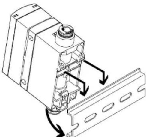
Technical line drawing of a mechanical assembly with directional arrows indicating movement or force (no text or symbols present)Fig. 6: Mounting on H-rail
- Attach the sensor to the DIN rail.
- Press the sensor in the direction of the arrow.
The sensor snaps into place.
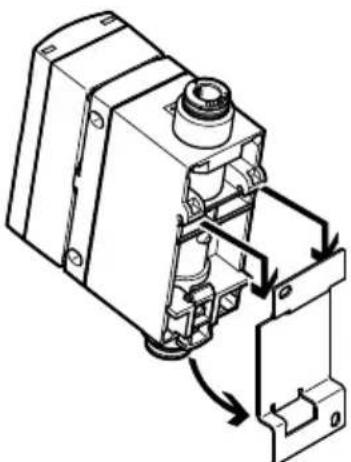
5.2 Mounting the sensor with wall mounting
natural_image
Technical line drawing of an electrical component with internal wiring and mounting bracket (no text or symbols)Fig. 7: Wall mounting
- Fasten the adapter plate with 2 screws M3.
- Attach the sensor to the adapter plate.
- Press the sensor in the direction of the arrow.
The sensor snaps into place.
Installation
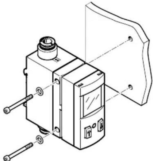
5.3 Mounting the sensor on the plate
natural_image
Technical line drawing of a mechanical device with labeled components (no text or symbols)Fig. 8: Plate mounting
- Fasten the sensor with washers and 2 screws M4. - Max. tightening torque: 1 Nm
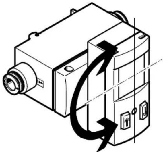
5.4 Rotating the display
The display can be rotated in 90° steps. The turning range is limited to approx. 270° by a stop.
natural_image
Technical line drawing of a mechanical device with directional arrows indicating motion or force (no text or symbols)Fig. 9: Rotate the display
6 Installation
6.1 Installation, pneumatic
The flow rate is supplied at connection 1 and withdrawn at connection 2. The direction of flow is indicated on the sensor by an arrow.
If the hoses are installed incorrectly, the negative measured values will flash on the display.
6.2 Installation, electrical
WARNING
Risk of injury due to electric shock.
- For the electrical power supply, use only PELV circuits in accordance with IEC 60204-1/EN 60204-1 (Protective Extra-Low Voltage, PELV).
- Observe the general requirements of IEC 60204-1/EN 60204-1 for PELV circuits.
-
Only use voltage sources that ensure a reliable electric separation from the mains network in accordance with IEC 60204-1/EN 60204-1.
-
Observe signal line length 13 Technical data.
-
Configure binary outputs according to the wiring.
- Tightening torque for the union nut at the plug connector: max. 0.3 Nm
| Plugs Pin Wire colour | 1) | Allocation | |
M12, 5-pin 1 Brown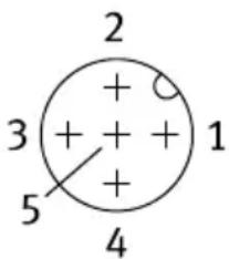 | (BN) Operating voltage +24 V DC | ||
| 2 White (WH) Electrical output | 2 (OutB or analogue) | ||
| 3 Blue (BU) Operating voltage | 0 V | ||
| 4 Black (BK) Electrical output | 1 (OutA, pulse, C/Q line with IO-Link) | ||
| 5 Grey (GY) NC | |||
1) When using the connecting cable from the accessories.
Tab. 10: Pin allocation
Circuit diagram
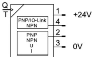
Fig. 10: Circuit diagram
7 Commissioning
7.1 Switching on the sensor in RUN mode
- Switch on the operating voltage.
The current measured value is displayed. The sensor is in the basic status.
The sensor is in the basic status in RUN mode. The sensor shows the current measured values. The basic status can be reached as follows from other modes:
-Press and hold the [Edit] key for 3 seconds.
-Expiration of monitoring time (timeout).
Commissioning
Switchover of measured value indicator
The measured value indicator can be switched between flow rate, temperature and volume/mass in RUN mode.
- Briefly press the [A] or [B] key.
- Repeat the process with a 1...3 second pause until the desired measured variable is displayed.
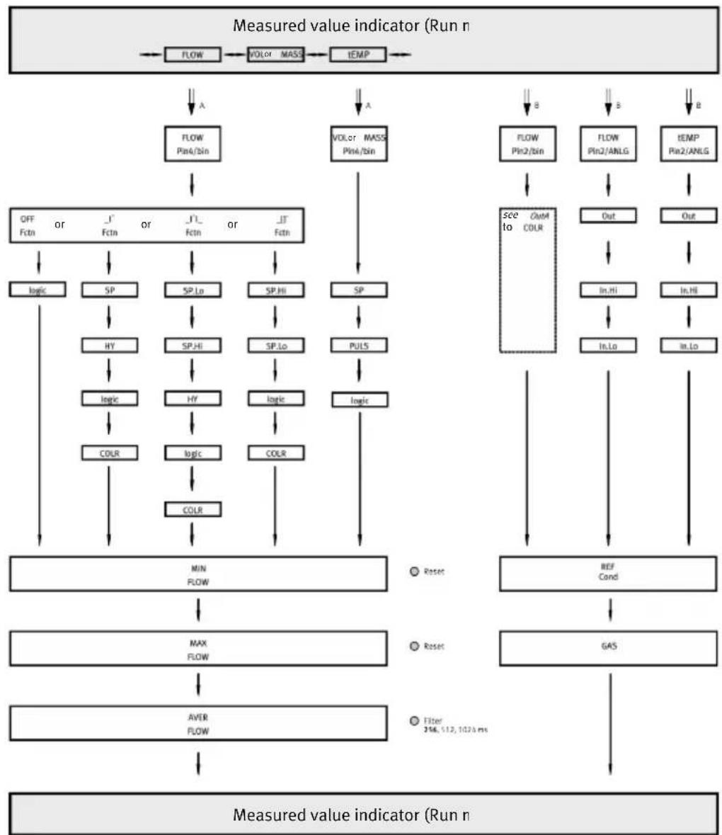
7.2 Displaying parameters in SHOW mode
Requirement: the sensor is ready for operation and is in RUN mode.
Switching output OutA or volume output
- Press the [A] key twice in rapid succession.
The first parameter set 'Pin4'/'bin' is displayed.
- Press the [A] pushbutton to display each of the following parameters → Fig. 11.
At the end, the flow rate values ‘MIN’, ‘MAX’ and ‘AVER’ are displayed.
Switching output OutB or analogue output Anlg
- Press the [B] pushbutton twice in rapid succession.
The first set parameter ‘Pin2’/‘ANLG’ or ‘Pin2’/‘bin’ is displayed.
- Press the [B] pushbutton to display each of the following parameters → Fig. 11.
Commissioning
flowchart
graph TD
    A["Measured value indicator (Run n)"] --> B["FLOW"]
    B --> C["VOL or MASS Pin4/bin"]
    C --> D["OFF Fctn or JFctn or JFctn or JFctn"]
    D --> E["logic"]
    D --> F["SP"]
    D --> G["SP,Lo"]
    D --> H["SP,Hi"]
    D --> I["SP,Lo"]
    D --> J["SP"]
    D --> K["PULS"]
    D --> L["logic"]
    D --> M["COLR"]
    D --> N["Logic"]
    D --> O["COLR"]
    D --> P["MIN FLOW"]
    P --> Q["MAX FLOW"]
    Q --> R["AVER FLOW"]
    R --> S["Measured value indicator (Run n)"]

    T["Flow Pin2/bin"] --> U["see to Out"]
    U --> V["CoM4 COLR"]
    W["FLOW Pin2/ANLG"] --> X["Out"]
    X --> Y["In,Hi"]
    Z["tEMP Pin2/ANLG"] --> AA["Out"]
    AA --> AB["In,Hi"]
    AC["REF Cond"] --> AD["GAS"]
    AE["Reset"] --> AF["Reset 314, 512, 1023 ms"]
    AF --> AG["Filter 314, 512, 1023 ms"]
![Button [A] or Button [B] Double click button [A] or button [B] Button [Edi]](/content/2026/05/855068/images/282e3a4458d04aff6ec417fa4e3e2d44f009f3b818fc1ab904c991bb233c1104.jpg)
Fig. 11: Menu structure for SHOW mode
7.3 Configuring the sensor in EDIT mode
flowchart
```mermaid
graph TD
    A["OutA Edit FLOW / Bm"] --> B["OutB Edit FLOW / bin"]
    B --> C["OutC Edit VOL / PULS"]
    C --> D["Anig Edit ANLG / Out"]
    D --> E["Spec Edit MENU"]

    subgraph Run r
        direction TB
        A -->|OFF| F1["Logic NO, NC"]
        A -->|OFF| F2["Logic NO, NC"]
        A -->|OFF| F3["Logic NO, NC"]
        A -->|OFF| F4["Logic NO, NC"]
        A -->|OFF| F5["Logic NO, NC"]
        A -->|OFF| F6["Logic NO, NC"]
        A -->|OFF| F7["Logic NO, NC"]
        A -->|OFF| F8["Logic NO, NC"]
        A -->|OFF| F9["Logic NO, NC"]
        A -->|OFF| F10["Logic NO, NC"]
        A -->|OFF| F11["Logic NO, NC"]
        A -->|OFF| F12["Logic NO, NC"]
        A -->|OFF| F13["Logic NO, NC"]
        A -->|OFF| F14["Logic NO, NC"]
        A -->|OFF| F15["Logic NO, NC"]
        A -->|OFF| F16["Logic NO, NC"]
        A -->|OFF| F17["Logic NO, NC"]
        A -->|OFF| F18["Logic NO, NC"]
        A -->|OFF| F19["Logic NO, NC"]
        A -->|OFF| F20["Logic NO, NC"]
        A -->|OFF| F21["Logic NO, NC"]
        A -->|OFF| F22["Logic NO, NC"]
        A -->|OFF| F23["Logic NO, NC"]
        A -->|OFF| F24["Logic NO, NC"]
        A -->|OFF| F25["Logic NO, NC"]
        A -->|OFF| F26["Logic NO, NC"]
        A -->|OFF| F27["Logic NO, NC"]
        A -->|OFF| F28["Logic NO, NC"]
        A -->|OFF| F29["Logic NO, NC"]
        A -->|OFF| F30["Logic NO, NC"]
        A -->|OFF| F31["Logic NO, NC"]
        A -->|OFF| F32["Logic NO, NC"]
        A -->|OFF| F33["Logic NO, NC"]
        A -->|OFF| F34["Logic NO, NC"]
        A -->|OFF| F35["Logic NO, NC"]
        A -->|OFF| F36["Logic NO, NC"]
        A -->|OFF| F37["Logic NO, NC"]
        A -->|OFF| F38["Logic NO, NC"]
        A -->|OFF| F39["Logic NO, NC"]
        A -->|OFF| F40["Logic NO, NC"]
    end

    subgraph Run r
        direction TB
        direction TB
    end

    note1[""Button [A"] or_Button["B""]
    note2["Button [Edit"]
    note3["fett Default"]

    %% Note: Diagram shows multiple input/output nodes connected by arrows. Numbers and labels in the diagram are not explicitly provided in the image. The diagram is a schematic representation of measurement indicators and outputs. Note numbers and symbols (e.g., SP, HY, color codes) are present in the diagram.
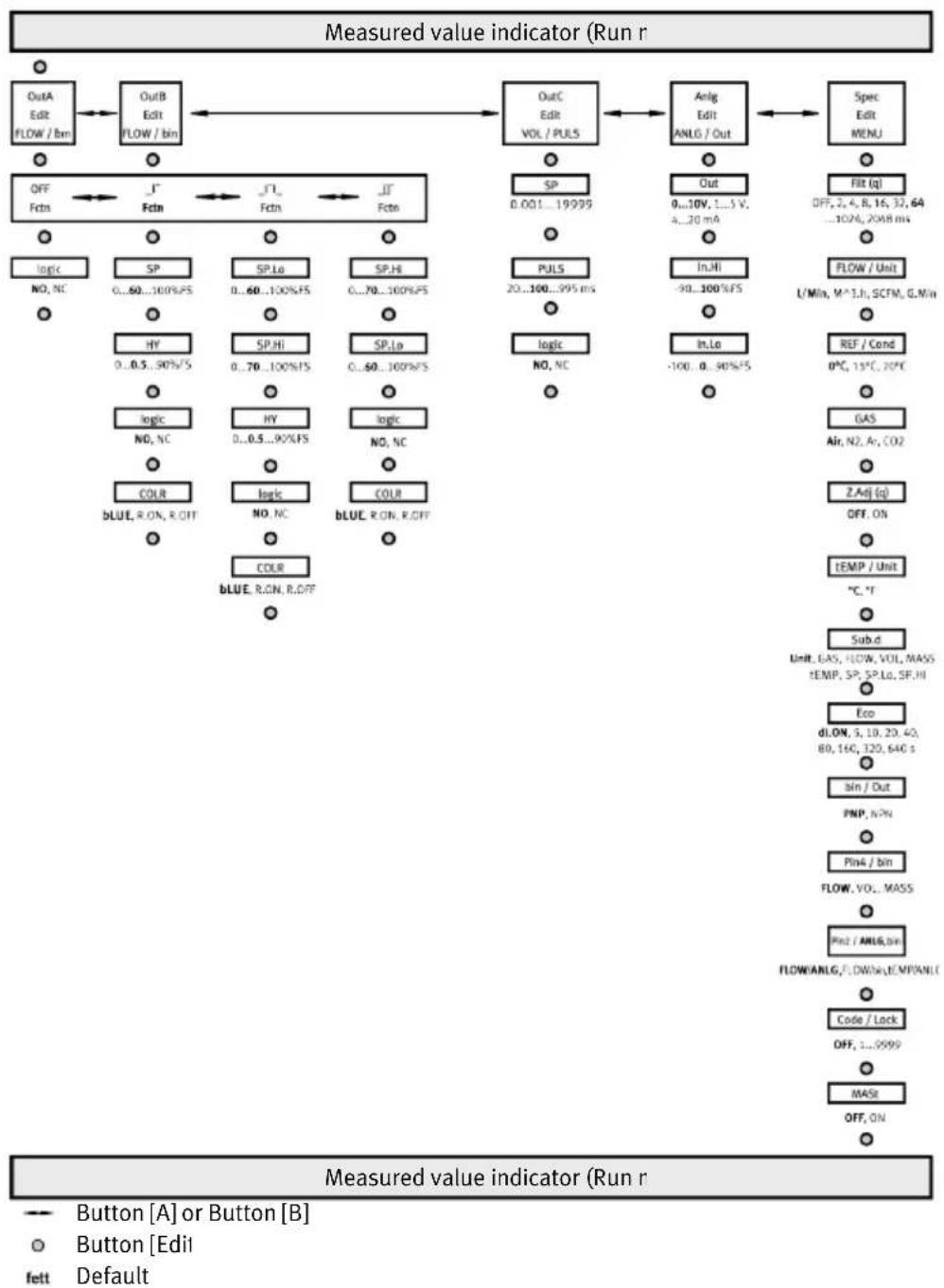
Fig. 12: EDIT mode menu structure
7.3.1 Starting EDIT Mode
Requirement: the sensor is ready for operation and is in RUN mode.
- Press the [Edit] key.
The EDIT mode is active. 'OutA' and 'Edit' are displayed.
- If the security code 'LOCK' is active, enter the security code using the [A] pushbutton or the [B] pushbutton and press the [Edit] key.
The EDIT mode is active. 'OutA' and 'Edit' are displayed.
7.3.2 Configuring the switching output
i
The process is basically the same for configuring the switching outputs for OutA and OutB. In the following, the process is described using the switching output OutA.
Requirement: EDIT mode is active.
- Press the [Edit] key.
'Fctn' flashes.
-
Select the switching function 'OFF', '_I-', '_I-' or cargo []' with the [A] or [B] key.
-
Press the [Edit] key.
The set value is saved. The next adjustable parameter is shown.
-
Set the parameter with the [A] or [B] key.
-
Repeat steps 3 and 4 until all parameters are set → Fig. 12.
-
Press the [Edit] key.
RUN mode is active.
7.3.3 Changing the device settings
Requirement: EDIT mode is active.
- Select the 'Spec' with the [A] or [B] key.
‘Spec’ is displayed.
- Press the [Edit] key.
→ ‘Filt’ / ‘MSEC’ flashes.
-
Set the parameter with the [A] or [B] key.
-
Press the [Edit] key.
The set value is saved. The next adjustable parameter is shown.
-
Repeat steps 3 and 4 until all parameters are set.
-
Press the [Edit] key.
RUN mode is active.
7.3.4 Setting the volume pulse output
Requirement: EDIT mode is active.
-
Select 'Puls' / 'VOL' with the A key or B key.
-
Press the [Edit] key.
→ 'SP' / 'Volume Unit' flashes.
-
Set the parameter with the [A] or [B] key.
-
Press the [Edit] key.
The set value is saved. The next adjustable parameter is shown.
-
Repeat steps 3 and 4 until all parameters are set.
-
Press the [Edit] key.
RUN mode is active.
7.3.5 Setting the analogue output
Requirement: EDIT mode is active.
- Select 'ANLG' / 'Out' with the A key or B key.
Commissioning
- Press the [Edit] key.
→ 'Out' / 'V' or 'Out' / 'MA' flashes.
-
Set the parameter with the [A] or [B] key.
-
Press the [Edit] key.
The set value is saved. The next adjustable parameter is shown.
-
Repeat steps 3 and 4 until all parameters are set.
-
Press the [Edit] key.
RUN mode is active.
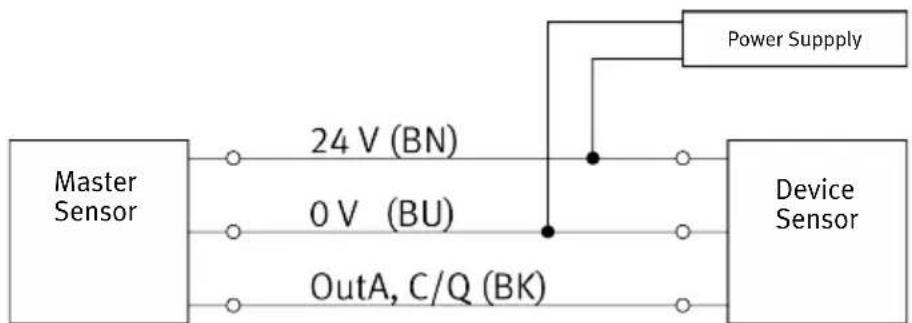
7.3.6 Replicating parameters
Requirements:
-The configured sensor (master sensor) is operational and in RUN mode.
- The master sensor and device sensor have the same design with reference to the parameters, i.e. they have the same device ID.
-The master sensor is connected with the device sensor Fig. 13.
-Parameterisation of the device sensor must not be blocked via IO-Link®.
flowchart
graph LR
    A["Master Sensor"] -->|24 V (BN)| B["Device Sensor"]
    A -->|0 V (BU)| B
    A -->|OutA, C/Q (BK)| B
    B -->|Power Supply| A
Fig. 13: Replicate pin allocation parameters
- Select the 'SPEC' special menu from the device settings on the master sensor.
- Press the [Edit] key repeatedly until 'MASt' appears.
- Select 'ON' with the [A] or [B] key.
- Press the [Edit] key.
→ 'REPL' and 'REdY' appear.
- Press the [A] or [B] key.
'REPL' and 'RUN' appear briefly. The parameters are transmitted to the device sensor. 'REPL' and 'REdY' appear. If an error occurs, an error message appears 11 Fault clearance.
- Repeat point 5 if an additional sensor should be parameterised.
- Press the [Edit] key.
RUN mode is active.
7.3.7 Zero point synchronisation
Requirements:
-‘Z.AdJ’ ‘ON’ is set.
-The operating pressure is present, but no flow rate exists.
- RUN mode is active.
- The measured value lies in the range 0 l/min ± 3 %FS.
- Press the [A] key and the [B] key.
Commissioning
- In addition, press the [Edit] button.
- If 'OK' appears: the zero point synchronisation was successful.
- ‘FAIL’ appears: the zero point synchronisation was not successful. Check requirements.
i
If [Z.AdJ][OFF] is set for a later time, the sensor takes over the factory setting calibration values.
7.4 Teaching the switching points in TEACH mode
The switching points for flow monitoring can be established in the TEACH mode 4.2.3 Switching outputs.
i
Before the teach-in, set the switching function to EDIT mode 7.3 Configuring the sensor in EDIT mode.
The procedure for teaching the OutA or OutB switching signal is the same in principle:
- OutA: press the [A] key.
- OutB: press the [B] key.
In the following, the procedure for the switching signal OutA is described.
Requirement: the sensor is ready for operation and is in RUN mode.
- Generate the flow rate for TP1.
- Press the [A] key and the [Edit] key.
With security code activated: [Lock] flashes.
- Set the security code with the [A] or [B] key.
- Press the [Edit] key.
‘t-IN’ flashes.
The measured value will then be applied as teach point (TP1).
- Generate the flow rate for TP2.
- Press the [A] key and the [Edit] key.
The measured value will then be applied as teach point (TP2).
The ‘SP’ switching point of the ‘SP.Lo’ and ‘SP.Hi’ switching points become valid.
The RUN mode is displayed.
7.5 Measuring volume manually in RECORDER mode
Requirement: the sensor is ready for operation and is in RUN mode.
- Press the [A] and [B] keys simultaneously.
The current status of the measurement is displayed.
- To start or stop the measurement, press the [A] key.
- To reset the measurement, press the [B] key.
- To exit RECORDER mode, press the [A] and [B] key simultaneously.
The RUN mode is displayed.
i
If the RECORDER mode is exited during a volume measurement, the measurement will continue in the background.
If the operating voltage is switched off, the measurement is aborted without saving the value.
8 IO-Link interface description
8.1 General information, IO-Link
| Feature Specification | |
| Protocol IO-Link | |
| Revision ID V1.1 | |
| Device profiles Smart Sensor - SSP 4.1.2Firmware Updateidentification and diagnosis | |
| Transmission rate COM3 | |
| SIO-Mode support Yes | |
| Port type class A | |
| Process data output length 0 bit | |
| Process data input length 64 bit | |
| Process data content IN Flow measurement value 16 bit MDCFlow monitoring 2 bit SSCTemperature measurement value 16 bit MDCTemperature monitoring 2 bit SSCVolume / mass pulse 1 bit SSC | |
| Service data IN Volume /mass measurement value 32 bit | |
| Min. cycle time | 1,2 ms |
| Data storage required | 0,5 kByte |
| Device ID | →Tab. 12 Device ID values |
Tab. 11: General IO-Link specification
| Device ID [dec] Device ID | [hex] Order code | |
| 329417 | 0x0506C9 | SFAB-10 |
| 329418 | 0x0506CA | SFAB-50 |
| 329419 | 0x0506CB | SFAB-200 |
| Device ID [dec] Device ID [hex] Order code | |
| 329420 0x0506CC SFAB-600 | |
| 329421 0x0506CD SFAB-1000 |
Tab. 12: Device ID values
8.2 Identification parameters
| Index Sub Index Access | 1) | Name Value String | length | |
| 0x0010(16) | 0x00 R Vendor Name Festo | 5 | ||
| 0x0011(17) | 0x00 | Vendor Text | http://www.festo.com | 20 |
| 0x0012(18) | 0x00 | Product Name Order Code,e.g. SFAB-10U-HQ6-PNLK-PNVBA-M12 | Max. 64 | |
| 0x0013(19) | 0x00 | Product ID | E.g. 563795 SFAB-10 | |
| 0x0014(20) | 0x00 | Product Text | Flow sensor | 11 |
| 0x0015(21) | 0x00 | Serial Number | Product Key,e.g. MW3N10KCP3X | 11 |
| 0x0016(22) | 0x00 | Hardware Revision | E.g. REV01 | 5 |
| 0x0017(23) | 0x00 | Firmware Revision | E.g. V8.8.5 | Max. 8 |
| 0x0018(24) | 0x00 | R/W | Application Specific Tag | *** |
| 0x0019(25) | 0x00 | Function Tag | *** | |
| 0x001A(26) | 0x00 | Location Tag | *** | |
| 0x001B(27) | 0x00 R Product URI | https://pk.festo.com/MW3N10KCP3X | Max. 32 | |
| 0x2101(8449) | 0x00 R Part Number | E.g. 8162824 | 7 | |
1) R = read, R/W = read and write
Tab. 13: Identification parameters
8.3 IO-Link default parameters
| Index Sub I | Index Access | 1) | Name Value Format | ||
| 0x0002(2) | 0x00 W System Command | →8.4 IO-Link system commands | UInter-gerT8 | ||
| 0x000C(12) | 0x00 R/W Device Access | Locks→Tab. 15 Device access blocking | bitwise0: unlocked1: locked | RecordT(16 bit) | |
| 0x0020(32) | 0x00 R Error | Count 0 ... 2 | ^16 – 1 UInter- | gerT16 | |
| 0x0024(36) | 0x00 Device Status 0: Device | Device is operating | properly2: Out-of-Specification4: Failure | UInter-gerT8 | |
| 0x0025(37) | 0x00 Detailed Device Status | Status Octet1 = event identi- | fierOctet2,3 = event code→8.10 Diagnostics IO-Link | ArrayT of Octet-StringT3 | |
| 0x0028(40) | 0x00 Process Data Input | →8.9 Process data IN | RecordT(64 bit) | ||
1) R = read, W = write, R/W = read and write Tab. 14: IO-Link default parameters
| Bit no. | Description |
| 0 | no used |
| 1 | no used |
| 2 | Local parameterization lock (EDIT- and TEACH-modes) |
| 3 | Local user interface lock (SHOW-, EDIT- and TEACH-modes) |
Tab. 15: Device access blocking
8.4 IO-Link system commands
| Value [dec] Value [hex] Command Description | |||
| 65 0x41 SP1 Single Value Teach Determines Teachpoint for Set- | point SP1 | ||
| 66 0x42 SP2 Single Value Teach Determines Teachpoint for Set- | point SP2 | ||
| 75 0x4B Specific Teach Two point teach according to | the teach flag | ||
| 76 0x4C Teach Cancel Cancels the Teach sequence | |||
| 126 0x7E Locator Start Display double flashing for | localization | ||
| 127 0x7F Locator Stop Stop double flashing | |||
| 128 0x80 Device reset Device warm start | |||
| 129 0x81 Application Reset Reset the technology sp | specific application | ||
| 130 0x82 Restore factory settings Sets the factory settings operative again | |||
| 131 0x83 Back-to-box Restore parameters to the original delivery values | |||
| 160 0xA0 Reset Min MDC1 (q) Minimal measured flow value reset | |||
| 161 0xA1 Reset Max MDC1 (q) Maximal measured flow value reset | |||
| 166 0xA6 Reset Min MDC2 (t) Minimal measured temperature value reset | |||
| 167 0xA7 Reset Max MDC2 (t) Maximal measured temperature value reset | |||
| 168 0xA8 Adjust flow zero point User defined flow zero point | adjustment | ||
| 176 0xB0 Reset volume / mass recorder | |||
| 177 0xB1 Run / resume volume / mass recorder | |||
| 178 0xB2 Pause volume / mass recorder | |||
Tab. 16: IO-Link system commands
8.5 Smart sensor profile parameters
| Index Sub | Index Access | 1) | Name Value Format | ||
| 0x000D(13) | 0x00 R Profile | Characteristics 0x0011, 0x0031,Profile ID 0x | 0x8101, 0x8102 | ArrayT of UInte-gerT16 | |
| 0x01 Device | 0011: Measuring and switching sensor, 2-channel (SSP 4.1.2) | UInte-gerT16 | |||
| 0x02 0x003 | 1: Firmware | ||||
| 0x03 Function | Class ID 0x | 8101: Extended iden-tification/localisation | |||
| 0x04 Function | Class ID 0x | 8102: Product URI | |||
| 0x000E(14) | 0x00 R PD | Input Descriptor | 0x03, 0x10, 0x30, | 0x03, 0x08, 0x28,0x01, 0x03, 0x20,0x03, 0x10, 0x10,0x03, 0x08, 0x08,0x01, 0x02, 0x00 | ArrayT of Octet-StringT3 |
| 0x01 Flow value MDC1 0x | MDC1 0x | 0x03, 0x10, 0x30 Octet- | StringT3 | ||
| 0x02 Flow scale MDC1 0x | MDC1 0x | 0x03, 0x08, 0x28 | |||
| 0x03 Flow monitoring | MDC1.1 (OutA), SSC1.2 (OutB), Volume / mass pulse SSC1.3 (OutC, Puls) | 0x01, 0x03, 0x20 | |||
| 0x04 Temperature | MDC2 | 0x03, 0x10, 0x10 | |||
| 0x05 Temperature scale | MDC2 | 0x03, 0x08, 0x08 | |||
| 0x06 Temperature moni- | toring SSC2.1, SSC2.2 | 0x01, 0x02, 0x00 | |||
| 0x003A(58) | 0x00 R/W | Teach | Channel 0: SSC | 1.1 (OutA)1: SSC1.1 (OutA), fac-tory setting2: SSC1.2 (OutB)11: SSC2.112: SSC2.2 | UInte-gerT8 |
| Index Sub Index Access | 1) | Name Value Format | |||
| 0x003B(59) | 0x00 R Teach | h Result 0: C | Combined value RecordT | (8 bit) | |
| 0x01 Teach | State 0: Idle, | default | 1: SP1 Success2: SP2 Success3: SP12 Success4: Wait for command5: Busy7: Error | UInte-gerT4(4 bit) | |
| 0x02 teach | flag TP1 for S | P1 0: not set | 1: set | BooleanT(1 bit) | |
| 0x03 teach | flag TP2 for S | P1 | |||
| 0x04 teach | flag TP1 for S | P2 | |||
| 0x05 teach | flagTP2 for SP | P2 | |||
| SSC1.1, flow rate monitoring (OutA) | |||||
| 0x003C(60) | 0x00 R/W S | SC1.1Param | Combined value RecordT | (64 bit) | |
| 0x01 Setpoint | int SP1 (SP, | SP.Lo, SP.Hi) | SFAB-10: 0 ... 6000SFAB-50: 0 ... 3000SFAB-200: 0 ... 12000SFAB-600: 0 ... 3600SFAB-1000: 0 ... 6000 | IntegerT32 | |
| 0x02 Setpoint | int SP2 (SP, | SP.Lo, SP.Hi) | SFAB-10: 0 ... 6000SFAB-50: 0 ... 3000SFAB-200: 0 ... 12000SFAB-600: 0 ... 3600SFAB-1000: 0 ... 6000 | ||
| 0x003D(61) | 0x00 R/W S | SC1.1Config | Combined value RecordT | (48 bit) | |
| 0x01 Switch | point logic | (logic) | 0: High-active (nor-mally open NO)1: Low-active (normally close NC) | UInte-gerT8 | |
| 0x02 Switch | point mode | (Fctn) | 0: Deactivated1: Single point mode (I^-)2: Window mode (I^-)3: Two point mode (I^-) | ||
| Index Sub | Index Access | 1) | Name Value Format | ||
| 0x003D(61) | 0x03 R/W H | ysteresis (HY) | SFAB-10: 0 ... 5400 | SFAB-50: 0 ... 2700SFAB-200: 0 ... 10800SFAB-600: 0 ... 3240SFAB-1000: 0 ... 5400 | IntegerT32 |
| SSC1.2, flow rate monitoring (OutB) | |||||
| 0x003E(62) | 0x00 R/W S | SC1.2Paramint SP1 (SP, | Combined value RecordT | (64 bit) | |
| 0x01 Setpoint | SP.Lo, SP.Hi) | SFAB-10: 0 ... 6000SFAB-50: 0 ... 3000SFAB-200: 0 ... 12000SFAB-600: 0 ... 3600SFAB-1000: 0 ... 6000 | IntegerT32 | ||
| 0x02 Setpoint | SP.Lo, SP.Hi) | SFAB-10: 0 ... 6000SFAB-50: 0 ... 3000SFAB-200: 0 ... 12000SFAB-600: 0 ... 3600SFAB-1000: 0 ... 6000 | |||
| 0x003F(63) | 0x00 R/W S | SC1.2Configpoint logicpoint mode | Combined value RecordT | (48 bit) | |
| 0x01 Switch | (logic) | 0: High-active (normally open NO)1: Low-active (normally close NC) | UInte-gerT8 | ||
| 0x02 Switch | (Fctn) | 0: Deactivated1: Single point mode (I~)2: Window mode (I~I_)3: Two point mode (I~I-) | |||
| 0x03 Hysteresis (HY) SFAB-10: 0 ... 5400 | SFAB-50: 0 ... 2700SFAB-200: 0 ... 10800SFAB-600: 0 ... 3240SFAB-1000: 0 ... 5400 | IntegerT32 | |||
| SSC2.1, temperature monitoring | |||||
| 0x400C(16396) | 0x00 R/W S | SC2.1Paramint SP1 0 ... 9 | Combined value RecordT | (64 bit) | |
| 0x01 Setpoint | 99 IntegerT32 | ||||
| Index Sub Index Access | 1) | Name Value Format | |||
| 0x400C(16396) | 0x02 R/W IntegerT32Setpoint SP2 0 ... 999 | ||||
| 0x400D(16397) | 0x00 R/W SSC2.1Configpoint logic | Combined value RecordT | (48 bit) | ||
| 0x01 Switchpoint mode | (logic) | 0: High-active (normally open NO)1: Low-active (normally close NC) | UInte-gerT8 | ||
| 0x02 Switchpoint mode | (Fctn) | 0: Deactivated1: Single point mode ( \_I^- )2: Window mode ( \_I^- )3: Two point mode ( \_I^- ) | |||
| 0x03 Hysteresis (HY) 0 ... | 900 IntegerT32 | ||||
| SSC2.2, temperature monitoring | |||||
| 0x400E(16398) | 0x00 R/W SSC2.2Parampoint SP1 0 ... 999 | Combined value RecordT | (64 bit) | ||
| 0x01 Setpoint SP2 0 ... 999 | IntegerT32 | ||||
| 0x02 Setpoint SP2 0 ... 999 | |||||
| 0x400F(16399) | 0x00 R/W SSC2.2Configpoint logicpoint mode | Combined value RecordT | (48 bit) | ||
| 0x01 Switchpoint logicpoint mode | (logic) | 0: High-active (normally open NO)1: Low-active (normally close NC) | UInte-gerT8 | ||
| 0x02 Switchpoint mode | (Fctn) | 0: Deactivated1: Single point mode ( \_I^- )2: Window mode ( \_I^- )3: Two point mode ( \_I^- ) | |||
| Ox03 Hysteresis (HY) 0 ... | 900 IntegerT32 | ||||
| Index Sub | Index Access | 1) | Name Value Format | ||
| MDC1, flow measurement descriptor | |||||
| 0x4080(16512) | 0x00 R MDC | 1Descr Combined value of measure of measurement range | SFAB-10: 60SFAB-50: 30SFAB-200: 120SFAB-600: 36SFAB-1000: 60 | IntegerT32 | |
| 0x01 Lower | |||||
| 0x02 Upper | value of measurement range | SFAB-10: 6000SFAB-50: 3000SFAB-200: 12000SFAB-600: 3600SFAB-1000: 6000 | |||
| 0x03 Unit code 1349 (m3/h) UInte- | gerT16 | ||||
| 0x04 Scale SFAB-10: -4 | (10) | SFAB-50: -3 (10-3)SFAB-200: -3 (10-3)SFAB-600: -2 (10-2)SFAB-1000: -2 (10-2) | IntegerT8 | ||
| MDC2, temperature measurement descriptor | |||||
| 0x4081(16513) | 0x00 R MDC | 2Descr Combined value of measurement range | 0 IntegerT32 | ||
| 0x01 Lower | |||||
| 0x02 Upper | value of measurement range | 500 | |||
| 0x03 Unit code 1001 (°C) | UInte- | gerT16 | |||
| 0x04 Scale -1 (10) | -1) IntegerT8 | ||||
1) R = read, R/W = read and write, - = no access
Tab. 17: Smart sensor profile parameters
8.6 Device-specific parameters
| Index Sub Index Access | 1) | Name Value Format | |||
| 0x0118(280) | 0x00 R/W backlight color (COLR) 0: allways blue (bLUE) | UInte-gerT16 | |||
| 1: red if OutA = 0,(R.OFF) | |||||
| 2: red if OutA = 1,(R.ON) | |||||
| 0x0136(310) | 0x00 backlight color (COLR) 0: allways blue (bLUE) | 1: red if OutB = 0,(R.OFF) | |||
| 2: red if OutB = 1,(R.ON) | |||||
| 0x3142(12610) | 0x00 Threshold of volume /mass pulse | mass pulse (PULS, SP) | Typically1 ... 200000000Scale: m3:SFAB-10: x 0,00001SFAB-50: x 0,0001SFAB-200: x 0,001SFAB-600: x 0,001SFAB-1000: x 0,001 | UInte-gerT32 | |
| 0x0147(327) | 0x00 Volume / mass pulse | switch point logic(PULS, logic) | 0: High-active (normally open NO)1: Low-active (normally close NC) | UInte-gerT16 | |
| 0x0149(329) | 0x00 Volume / mass pulse | length (PULS, MSEC) | 20 ... 995 ms | ||
| 0x016A(362) | 0x00 Analog output scaling | start value (Anlg,In.Lo / %) | -100 ... 90 IntegerT16 | ||
| 0x016B(363) | 0x00 Analog output scaling | end value (Anlg, In.Hi /%) | -90 ... 100 | ||
| 0x016C(364) | 0x00 Analog output type | (Anlg, Out) | 0: 0 ... 10 V voltage output1: 1 ... 5 V voltage output2: 4 ... 20 mA current output | UInte-gerT16 | |
| 0x017F(383) | 0x00 R/W flow unit of the display filter | dis-play(q, FLOW/Unit) | 0: l/min2: m^3/h 3: scfm4: g/min | UInte-gerT16 | |
| 0x0181(385) | 0x00 Flow d | MDC1 (q, AVER) | 8: 256 ms9: 512 ms10: 1024 ms | ||
| 0x0182(386) | 0x00 Flow f | time MDC1 (q, Filt) | 0: Filter off1: 2 ms2: 4 ms3: 8 ms4: 16 ms5: 32 ms6: 64 ms7: 128 ms8: 256 ms9: 512 ms10: 1024 ms11: 2048 ms | ||
| 0x0184(388) | 0x00 User z | zero adjustmenton/off (Z.Adj) | 0: off1: on | ||
| 0x01A7(423) | 0x00 R Volume / mass un | unit 0: l | 1: m^3 2: scf3: g | ||
| 0x01BB(443) | 0x00 R/W T | temperature un | unit MDC2(t, tEMP/Unit) | 0: °C1: °F | |
| 0x01DC(476) | 0x00 Show | local SSCs in | RUN mode on the dis-play | 0: Only active SSCs1: All local SSCs | |
| 0x01DD(477) | 0x00 Measu | red value dis | play 0: flow | 1: Volume / mass pulse2: temperature | |
| 0x01E1(481) | 0x00 Digital | output hard | waremode (Out/bin) | 0: NPN1: PNP | |
| 0x01E2(482) | 0x00 R/W Pin2 selection | 0: Flow monitoring | SSC1.2 (OutB, FLOW, bin)2: Flow measurement value MDC1 (FLOW, ANLG, q)4: Temperature measurement value MDC2 (tEMP, ANLG, t) | UInte-gerT16 | |
| 0x01E3(483) | 0x00 Pin4 selection 0: Flow | low monitoring | SSC1.1 (OutA, FLOW, bin)1: Volume / mass pulse SSC1.3 (OutC, VOL, bin) | ||
| 0x01E8(488) | 0x00 Backlight duration | (Eco) | 0: always on1: 5 s2: 10 s3: 20 s4: 40 s5: 80 s6: 160 s7: 320 s8: 640 s | ||
| 0x01E9(489) | 0x00 Sub-display mode | (Sub.d) | 0: units (Unit)1: Gas type (GAS)2: Flow measurement value (FLOW)3: Volume /mass measurement value (VOL, MASS)5: Temperature measurement value (tEMP)6: SP1 OutA (SP, SP.Lo, SP.Hi)7: SP2 OutA (SP, SP.Lo, SP.Hi) | ||
| 0x01EA(490) | 0x00 Lock code, local par | am-eter lock (Code, Lock) | 0: Off1 ... 9999 | ||
| 0x01EE(494) | 0x00 Gas type (VAS) | air (Air) | 1: nitrogen (N2)2: argon (Ar)3: carbon dioxid (CO2) | gerT16 | |
| 0x01F0(496) | 0x00 R/W | dition for volume values (REF/Cond) | 0: DIN 1343 (0 °C)1: ISO 2533 (15 °C)2: ISO 6358 (20 °C) | ||
| 0x2081(8321) | 0x00 R Flow | (value MDC1) | ^15 ... 2^15-1 IntegerT16 | ||
| 0x2083(8323) | 0x00 value of volume / m | mass pulse (PULS) | Typically1 ... 200000000Scale m3:SFAB-10: x 0,00001SFAB-50: x 0,0001SFAB-200: x 0,001SFAB-600: x 0,001SFAB-1000: x 0,001 | UInte-gerT32 | |
| 0x2084(8324) | 0x00 Temperture value | MDC2 (t) | -2^15 ... 2^15-1 IntegerT16 | ||
| 0x2085(8325) | 0x00 value of volume / m | mass recorder (REC) | Typically1 ... 200000000Scale m3:SFAB-10: x 0,00001SFAB-50: x 0,0001SFAB-200: x 0,001SFAB-600: x 0,001SFAB-1000: x 0,001 | UInte-gerT2 | |
| 0x2088(8328) | 0x00 Minimum measured | flow rate value MDC1(MIN, q) | -2^15 ... 2^15-1 IntegerT16 | ||
| 0x2089(8329) | 0x00 Maximum measured | flow rate value MDC1(MAX, q) | -2^15 ... 2^15-1 | ||
| 0x208E(8334) | 0x00 Time of volume / m | ass recorder | 0 ... 2^32-1 s UInte- | gerT32 | |
| 0x208F(8335) | 0x00 Error time of volume / voltage | mass recorder | 0 ... 2^32-1 s | ||
| 0x2090(8336) | 0x00 Supply voltage | Scale x 0,1 V | Example: 240: 24,0 V | UInte-gerT16 | |
| Index Sub Index Access | 1) | Name Value Format | |||
| 0x2092(8338) | R0x00 minimal measured value averaged | mal measured temperature value MDC2 (MIN, t) | -2^15 2^15-1 IntegerT16 | ||
| 0x2093(8339) | 0x00 maximal | temperature value MDC2 (MAX, t) | -2^15 2^15-1 | ||
| 0x2094(8340) | 0x00 Flow value | MDC1 (AVER, q) | -2^15 2^15-1 | ||
| 0x2095(8341) | 0x00 Analogue | voltage in V | Scale x 0,001 VExample: 2874: 2,874 V | UInte-gerT16 | |
| 0x2096(8342) | 0x00 Current at the analogue | output in mA | Scale x 0,01 mAAxample: 861: 8,61 mA | ||
1) R = read, R/W = read and write, - = no access
Tab. 18: Device-specific parameters
8.7 IO-Link teach-in
The sensor supports two different IO-Link teach functions for all IO-Link switching channels (SSC):
– Single value teach-in according to IO-Link specification
- Device-specific teach-in
Carry out the following steps before teaching:
- Configure the switching channel according to the application including switching mode, switching logic and hysteresis.
The switching mode must not be deactivated (OFF).
- Set the teach channel to the desired switching channel (parameter 0x003A).
Single value teach-in according to IO-Link specification
With the single value teach-in, SP1 and SP2 are taught in with separate commands. After each command, the parameter set of the switching channel is checked for validity. If the parameter set is valid, the teach point is immediately accepted as the switching point. If the parameter set is invalid, the process is aborted.
- Set the desired flow rate.
- Perform the teach process: 0x41 for SP1 and 0x42 for SP2.
- To set the second switching point, repeat steps 1 and 2.
For more information, see IO-Link Smart Sensor Profile.
Device-specific teach-in
The device-specific teach-in (0x4B) behaves in the same way as the manual teach-in on the device. Instead of pressing a button manually, the two teaching points are set with the IO-Link command. The chronological order is irrelevant. In the window mode and in the two-point mode, the 2 teaching points are assigned to the switching points SP1 and SP2 in such a way that the parameter set is valid. The
teach values are only accepted after the second teach-in. With the teach-in of the single point mode, the switching point results from the mean value of the two teaching points: SP = 1/2 (TP1 + TP2). The keys [A], [B] and [Edit] are locked during the teach-in. The display flashes alternately 't-IN' and 'IOL'.
- Set the first desired flow rate.
- Send the teach-in command 0x4B.
-
Set the second desired flow rate.
-
Send the teach-in command 0x4B.
The teach process is aborted with the command 0x4C.
Recommendation: After teaching, read out the parameter set and check whether the settings match the application.
8.8 Block parameterisation
Block parameterisation is used to prevent individual parameter values from being incompatible with the values stored in the device. All parameters transmitted as a block will be simultaneously accepted and activated.
| Index Subindex Name | ||
| 0x003C(60) | 0x01 Setpoint SP1 | |
| 0x02 Setpoint SP2 | ||
| 0x003D(61) | 0x02 Switchpoint mode | |
| 0x03 Hysteresis |
Tab. 19: Block parameterisation for flow rate monitoring SSC1.1 (OutA)
| Index Subindex Name | ||
| 0x003E(62) | 0x01 Setpoint SP1 | |
| 0x02 Setpoint SP2 | ||
| 0x003F(63) | 0x02 Switchpoint mode | |
| 0x03 Hysteresis |
Tab. 20: Block parameterisation for flow rate monitoring SSC1.2 (OutB)
| Index Subindex Name | ||
| 0x3142(12610) | 0x00 Threshold of volume / mass pulse | |
| 0x0149(329) | 0x00 Volume /mass pulse length | |
Tab. 21: Block parameterisation for volume pulse/mass pulse SSC1.3 (OutC)
| Index Subindex Name | ||
| 0x400C(16396) | 0x01 Setpoint SP1 | |
| 0x02 Setpoint SP2 | ||
| 0x400D(16397) | 0x02 Switchpoint mode | |
| 0x03 Hysteresis |
Tab. 22: Block parameterisation for temperature monitoring SSC2.1
| Index Subindex Name | ||
| 0x400E(16398) | 0x01 Setpoint SP1 | |
| 0x02 Setpoint SP2 | ||
| 0x400F(16399) | 0x02 Switchpoint mode | |
| 0x03 Hysteresis |
Tab. 23: Block parameterisation for temperature monitoring SSC2.2
| Index Subindex Name | ||
| 0x016A(362) | 0x00 Analog output scaling, start value | |
| 0x016B(363) | 0x00 Analog output scaling, end value | |
Tab. 24: Block parameterisation for analogue output scaling
8.9 Process data IN
| Bit 63 ... 48 47 ... | 40 39 ... 35 34 33 32 | |||||
| Process data MD | C1-Value MDC1 scaling no used SSC1.3 | SSC1.2 SSC1.1 | ||||
| Data content 16- | Bit flow (q) 8-bit decimal exponent | OutC Puls | OutB OutA | |||
| Index 0x00028 0x0028 | ||||||
| SubIndex 0x01 0x02 0x05 0x04 0x03 | ||||||
| Data type | Integer16 | Integer8 | Boolean | |||
Tab. 25: Process data IN MDC1 (flow rate)
| Bit 31 ... 16 15 ... | 8 | 7 ... 2 | 1 | 0 | ||
| Process data MD | C2-Value MDC2-Scale | no used SSC2.2 | SSC2.1 | |||
| Data content 16-bit temperature (t) | 8-bit decimal exponent | |||||
| Index 0x00028 0x0028 | ||||||
| SubIndex 0x0B | 0x0C 0x0E | 0x0D | ||||
| Data type | Integer16 | Integer8 | Boolean | |||
Tab. 26: Process data IN MDC2 (temperature)
8.10 Diagnostics IO-Link
| Event code [hex] | Device status | Event type | Local display | Possible cause |
| 0x1000 | 4: Failure | 3: Error | Er01 | Device error |
| 0x1808 | Er08 | Moisture or dirt in the compressed air | ||
| 0x1815 | Er21 | Overload or short circuit at the switching output OutA/Puls | ||
| 0x1816 | Er22 | Overload or short circuit at the switching output OutB | ||
| 0x181F 0: Device is operating properly | 1: Notification | Volume/mass recorder counter overflow | ||
| Event code [hex] | Device status Event type Local display | Possible cause | ||
| 0x4000 4: Failure 3: Error Er20 Temperature fault in IO-Link | driver | |||
| 0x5111 2: Out-of-Specifi-cation | 2: Warning Er17 Supply voltage under-run | |||
Tab. 27: Diagnostics IO-Link
9 Operation
i
Changes to the device settings take effect immediately at the outputs.
i
Ready-state delay
Note the ready-state delay. After this time, the electrical outputs take a defined, stable condition.
The flow rate displayed refers to the standard condition that was set in the Spec menu under 'REF' / 'Cond'.
When comparing volumetric flow rates, note the following:
- Make sure that the volumetric flow rates to be compared refer to the same standard conditions, e.g. operating volumetric flow rate, amount supplied by a compressor, measured values of a sensor from another manufacturer.
- After the supply voltage is switched on, note the warm-up time before it reaches the specified accuracy 13 Technical data.
9.1 Reset sensor to factory setting
i
By resetting to the factory settings, the current settings are lost. Note down current settings before resetting.
- Switch off the operating voltage.
- Press and hold the [A] button, the [B] button, and the [Edit] button.
- Switch on the operating voltage.
The sensor is in RUN mode.

10 Cleaning
- Turn off energy source and compressed air.
- Clean the outside of the sensor with media that are gentle on the material.
11 Fault clearance
| Malfunction / display Possible cause Remedy | |||
| Main display Lower display | |||
| Settings cannot be edited;‘Lock’ appears. | Security code activated. | - Enter security code or restore factory settings → 9.1 Reset sensor to factory setting. | |
| ‘Er01’ Error related Device error. | - Replace sensor. | ||
| ‘Er08’ ‘diaP’ Moisture or dirt in the compressed air. | - Replace sensor. | ||
| -200%FS ‘Er09’/‘UNdR’ Below sensing range. | - Maintain flow measuring range. | ||
| +200%FS ‘Er10’/‘OVER’ Sensing range exceeded | - Maintain flow measuring range. | ||
| ‘Er17’/‘SUPL’ Power supply too low. | - Check power supply. | ||
| ‘Er20’/‘t.Hi’ Temperature error in IO-Link driver. | - Eliminate short circuit or overload. | ||
| ‘Er21’/‘SHRt’ Overload or short circuit at the OutA, OutC switching output. | - Eliminate short circuit. | ||
| ‘Er22’/‘SHRt’ Overload or short circuit at the switching output OutB. | - Eliminate short circuit. | ||
| REC reading flashes | - | Measured value was outside the measuring range. | |
| ‘Err’ / ‘Id’ ‘REPL’ | IO-Link DeviceID error, devices are not identical. | - When replicating, use sensors with the same measuring range or type. | |
| ‘Err’ / ‘COM’ | ‘REPL’ | IO-Link communication error. | - Check line OutA.- Check settings of the device sensor. |
Tab. 28: Fault clearance
12 Dismantling
- Turn off energy source and compressed air.
- Disconnect connections from the sensor.
- For panel mounting: loosen retaining screws.
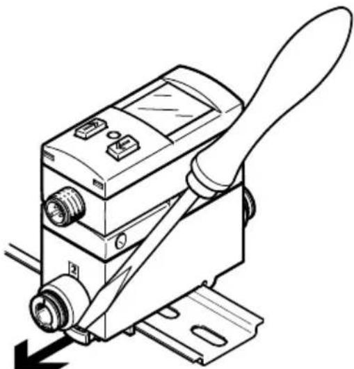
For H-rail mounting: loosen the mounting slide.
natural_image
Technical line drawing of a mechanical device with a handle and lever mechanism (no text or symbols)Fig. 14: Dismantling
13 Technical data
| SFAB -10U -50U -200U -600U -1000U | |||||
| General | |||||
| Certification RCM mark | |||||
| Declaration of conformity | → www.festo.com/sp | ||||
| Input signal and measurement signal | |||||
| Measured variable | - Volumetric flow rate- Mass flow rate- Temperature- Volume | ||||
| Flow direction Unidirectional P1 → P2 | |||||
| Measurement principle Thermal | |||||
| Measurement method Heat loss | |||||
| Warm-up time [min] ≥ 5 | |||||
| Flow measuring range, [l/min] 0.1 ... compressed air | 10 0.5 ... 50 | 2 ... 200 | 6 ... 600 | 10 ... 1000 | |
| Flow measuring range, [l/min] 0.1 ... argon | 10 0.5 ... 50 | 2 ... 200 | 6 ... 500 | 10 ... 500 | |
| Flow measuring range, [l/min] CO2 | 0.1 ... 5 | 0.5 ... 25 | 2 ... 100 | 6 ... 300 | 10 ... 500 |
| Temperature measuring range [°C] | 0 ... 50 | ||||
| Operating pressure [MPa] | 0 ... 1 | ||||
| [bar] | 0 ... 10 | ||||
| Operating pressure [psi] 0 ... 145 | |||||
| Nominal pressure [MPa] 0.6 | |||||
| [bar] 6 | |||||
| [psi] 87 | |||||
| Ambient temperature [°C] 0 ... 50 | |||||
| Temperature of medium [°C] 0 ... 50 | |||||
| Operating medium Compressed air to ISO | 8573-1:2010 [6:4:4] | Compressed air to ISO8573-1:2010 [7:4:4] | |||
| Nitrogen | |||||
| Argon | |||||
| Carbon dioxide | |||||
| Output, general ^1) 2) | |||||
| Values for flow rate | |||||
| Accuracy of compressed air zero point3) | [% FS] ± 0.3 | ||||
| Accuracy of zero point argon, CO _2 4) | [% FS] ± 2 | ||||
| Accuracy of spread3) | [% FS] ± 3 | ||||
| Repetition accuracy of zero point | [% FS] ± 0.2 | ||||
| Repetition accuracy of spread | [% FS] ± 0.8 | ||||
| Temperature coefficient zero point | [% FS/K] Max. ± 0.05 (typically 0) | ||||
| Temperature coefficient of spread | [% FS/K] Typically ± 0.1 | ||||
| Pressure influence of spread | [% FS/MPa] | Typically ± 5 | |||
| [% FS/bar] | Typically ± 0.5 | ||||
| [% FS/psi] | Typically ± 0.035 | ||||
| Values for temperature | |||||
| Accuracy of measured temperature value | [°C] Typically | ± 5In the thermally steady state in the flow rate range:20 ... 100 % FS | |||
| Switching output | |||||
| Switching output 2 PNP or 2 NPN, switchable | |||||
| Switching function Window comparator | Threshold value comparator2-point threshold value comparator | ||||
| Switching element function N/C contact | or N/O contact, switchable | ||||
| Max. output current [mA] 100 | |||||
| Voltage drop [V] Max. 1 | |||||
| Max. switch-on time [ms] 10 (at Filt = OFF) | |||||
| Max. switch-off time [ms] 10 (at Filt = OFF) | |||||
| Pull down resistor | PNP: integrated | ||||
| Pull-up resistor | NPN: integrated | ||||
| Inductive protective circuit | Present | ||||
| Analogue output | |||||
| Characteristic flow rate [l/min] curve | 0 ... 10 | 0 ... 50 | 0 ... 200 | 0 ... 600 | 0 ... 1000 |
| Characteristic temperature [°C] curve | 0 ... 100 | ||||
| Output characteristic analogue output [V] 0 ... 10 or [mA] | 1 ... 5 | ||||
| 4 ... 20 | |||||
| Max. load resistance of current output [Ω] | 500 | ||||
| Min. load resistance at voltage output [kΩ] | 20 | ||||
| Rise time t90 [ms] 10 (at Filt = Off) | |||||
| Output, additional data | |||||
| Short circuit current rating | Yes | ||||
| Overload protection | Present | ||||
| SFAB -10U -50U -200U -600U -1000U | ||||
| Communication interface | ||||
| IO-Link, Revision ID V1.1 | ||||
| IO-Link, device profile | - Smart Sensor - SSP 4.1.2- Firmware update- Identification and diagnostics- Function measurement data, standard resolution- Function multiple switching signal- Function teach single value- Function extended identification- Function locator- Function Product URI | |||
| IO-Link, transmission rate COM3 | ||||
| IO-Link, SIO mode support Yes | ||||
| IO-Link, port type Class A | ||||
| IO-Link, process data [bit] 0 length output | ||||
| IO-Link, input process [bit] 64 data length | ||||
| IO-Link, process data content IN | - Flow rate measurement 16 bit MDC- Flow rate monitoring 2 bit SSC- Measured temperature value 16 bit MDC- Temperature monitoring 2 bit SSC- Volume pulse/mass pulse 1 bit SSC | |||
| IO-Link, service data content IN Volume | reading/mass reading 32 bit | |||
| IO-Link, minimum cycle [ms] 1.2 time | ||||
| IO-Link, data memory [Kbyte] 0.5 required | ||||
| Electronics | ||||
| Operating voltage range [V DC] 15 ... 30 | ||||
| No-load current (at 24 V [mA] DC and 100% flow) | 90 | |||
| Max. ready-state delay [ms] 500 | ||||
| Reverse polarity protection | For all electrical connections | |||
| SFAB -10U -50U -200U -600U -1000U | |||||
| Electromechanics | |||||
| Electrical connection Plug connector, M12x1, A-cod., according to EN 61076-2-101 | |||||
| Max. connecting cable [m] 30 length | 20 for IO-Link operation | ||||
| Mechanics | |||||
| Mounting position Any | |||||
| Note on materials for housing PA-reinforced | |||||
| Note on materials for inspection window | PA | ||||
| Display and operation | |||||
| Displayable units | - l/min- m3/h- scfm- g/min- l- m3- scf- g | ||||
| Immission and emission | |||||
| Storage temperature [°C] -20 ... +80 | |||||
| Degree of protection in accordance with EN 60 529 | IP65 | ||||
| Standard nominal flow [l/min] 43.5 rate according to ISO6358/ISO 8778 | 163 760 1630 1630 | ||||
1) Accuracy under nominal conditions (6 bar, 23 °C and horizontal mounting position)
2) % FS = % of the flow rate range end value (full scale)
3) The accuracy of the zero point and accuracy of the spread together correspond to the accuracy of the flow rate: accuracy of the flow rate = ± (0.3% FS + 3% o.m.v.). % o.m.v. = % of measured value
4) In relation to the flow rate measuring range end value for air
Tab. 29: Technical data
13.1 Examples for calculating the maximum error of the display
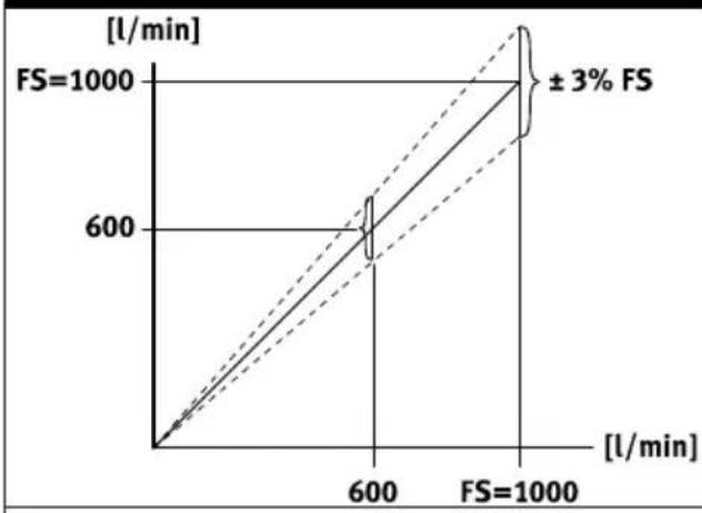
- Flow rate measuring range: 10 ... 1000 l/min (FS = 1000)
- Measured value: 600 l/min
Spread error (e.g. ± 3 % FS) Zero point error
line
| FS | [l/min] | | ------ | ------- | | 1000 | 600 | | 1000 | 600 |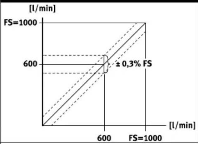
line
| FS Value | Time [L/min] | | -------- | ------------ | | 1000 | 600 | | 1000 | 1000 |Tab. 30: Spread error and zero point error
Spread error and zero point error
The spread error is proportional to the measured value. At 600 l/min, the spread error is 3% of the measured value = 18 l/min.
The zero point error is independent of the measured value. It is 0.3% FS = 3 l/min.
Display error under nominal conditions (6 bar, 23 °C):
The display error under nominal conditions is the result of adding the spread and zero point errors. The actual flow rate is in the range of 600 ± (18+3) l/min = 600 ± 21 l/min.
Display error under deviating nominal conditions (e.g. 8 bar, 40 °C):
Temperature and pressure errors are spread errors. The temperature error at 40 °C is ±0.1% FS/K x 17 K = ±1.7% of the measured value = ±10.2 l/min.
The pressure error at 8 bar is ± 0.5% FS/bar x 2 bar = ± 1% of the measured value = ± 6 l/min.
The error of the display at deviating nominal conditions results from the addition of all error values (span, zero point, temperature, pressure). The actual flow rate is therefore in the range of 600 ± (18 + 3 + 10.2 + 6) l/min = 600 ± 37.2 l/min.
Copyright:
Festo SE & Co. KG
73734 Esslingen
Ruiter Straße 82
Deutschland
Phone:
+49 711 347-0
Internet:
- FESTO
- Table of contents
- Applicable Documents....5
- Safety....5
- Additional information....5
- Product overview.... 6
- Mounting....14
- Installation.... 16
- Commissioning....17
- IO-Link interface description.... 25
- Operation.... 42
- Cleaning.... 42
- Applicable Documents
- Safety
- Safety instructions
- Intended use
- Training of qualified personnel
- Additional information
- Product overview
- Structure
- Function
- Functional principle
- Product overview
- Operating statuses
- Switching outputs
- Switching functions
- Colour change
- Volume measurement and mass measurement
- Filter
- Analogue output
- Analogue signal
- Output signal
- Scaling of the analogue signal
- Security code
- Minimum value and maximum value
- Replication of the parameters
- Switchover of standard condition
- Zero point synchronisation
- Mounting
- Mounting the sensor on the H-rail
- Mounting the sensor with wall mounting
- Mounting the sensor on the plate
- Rotating the display
- Installation
- Installation, pneumatic
- Installation, electrical
- WARNING
- Risk of injury due to electric shock.
- Circuit diagram
- Commissioning
- Switching on the sensor in RUN mode
- Commissioning
- Switchover of measured value indicator
- Displaying parameters in SHOW mode
- Switching output OutA or volume output
- Switching output OutB or analogue output Anlg
- Configuring the sensor in EDIT mode
- Starting EDIT Mode
- Configuring the switching output
- i
- Changing the device settings
- Setting the volume pulse output
- Setting the analogue output
- Replicating parameters
- Requirements:
- Zero point synchronisation
- Teaching the switching points in TEACH mode
- Measuring volume manually in RECORDER mode
- IO-Link interface description
- General information, IO-Link
- IO-Link teach-in
- Single value teach-in according to IO-Link specification
- Device-specific teach-in
- Block parameterisation
- Process data IN
- Diagnostics IO-Link
- Operation
- Ready-state delay
- Reset sensor to factory setting
- Cleaning
- Dismantling
- Examples for calculating the maximum error of the display
- Spread error and zero point error
- Display error under nominal conditions (6 bar, 23 °C):
- Display error under deviating nominal conditions (e.g. 8 bar, 40 °C):
Brand : Festo
Model : SFAB-600U-HQ10-PNLK-PNVBA-M12
Category : Meter