
SDBT-MSX-1L-NU-E-2.5-N-LE - Detector Festo - Free user manual and instructions
Find the device manual for free SDBT-MSX-1L-NU-E-2.5-N-LE Festo in PDF.


| Product Type | Magnetic Cylinder Sensor (T-slot) |
| Brand | Festo |
| Model | SDBT-MSX-1L-NU-E-2.5-N-LE |
| Category | Detector |
| Dimensions | Approx. 25 x 5 x 15 mm (L x W x H) |
| Weight | Approx. 20 g |
| Cable Length | 2.5 m |
| Supply Voltage | 10 - 30 V DC |
| Switching Output | NPN, normally open (NO) |
| Max. Switching Current | 100 mA |
| Protection Class | IP67 |
| Operating Temperature | -25 °C to +70 °C |
| Housing Material | PA (Polyamide) |
| Mounting Type | T-slot nut insert |
| LED Indicator | Yes (switching state) |
| Short-circuit Protection | Yes |
| Reverse Polarity Protection | Yes |
| Maintenance | No regular maintenance required; keep clean |
| Cleaning Instructions | Wipe with dry cloth; do not use solvents |
| Safety Notes | Disconnect power before installation; observe voltage limits |
| Spare Parts / Repairability | Not user-repairable; replace entire sensor |
| Certifications | CE, RoHS |
Frequently Asked Questions - SDBT-MSX-1L-NU-E-2.5-N-LE Festo
User questions about SDBT-MSX-1L-NU-E-2.5-N-LE Festo
0 question about this device. Answer the ones you know or ask your own.
Ask a new question about this device
Download the instructions for your Detector in PDF format for free! Find your manual SDBT-MSX-1L-NU-E-2.5-N-LE - Festo and take your electronic device back in hand. On this page are published all the documents necessary for the use of your device. SDBT-MSX-1L-NU-E-2.5-N-LE by Festo.
USER MANUAL SDBT-MSX-1L-NU-E-2.5-N-LE Festo
natural_image
Technical line drawing of a mechanical component with no visible text or symbolsFESTO
Festo SE & Co. KG
Ruiter Straße 82
73734 Esslingen
Germany
+49 711 347-0
www.festo.com
Instructions | Operating
8125856
2019-11a
[8125858]



Translation of the original instructions
© 2019 all rights reserved to Festo SE & Co. KG
1 Further applicable documents
i
All available documents for the product → www.festo.com/pk.
2 Safety
2.1 Intended use
This product is intended for sensing the position of magnets (e. g. the piston position) in Festo products. The device is intended for use in an industrial environment.
2.1.1 Area of application and approval
In combination with the UL inspection mark on the product, the information in this section must also be observed in order to comply with the certification conditions of Underwriters Laboratories Inc. (UL) for USA and Canada.
| UL approval information | |
| Product category code NRKH, NRKH7 | |
| File number E232949 | |
| Considered standards UL 60947-1, UL 60947-5-2 | C22.2 No. 60947-1, C22.2 No. 60947-5-2 |
| UL mark | c US LISTED |
Tab. 1
Only use power sources which guarantee reliable electrical isolation of the operating voltage in accordance with IEC/EN 60204-1. Observe also the general requirements for PELV power circuits in accordance with IEC/EN 60204-1. Only for connection to a NEC/CEC Class 2 supply. The device shall be supplied from an isolating transformer having a secondary listed fuse rated 1 A.
3 Product overview
3.1 Structure
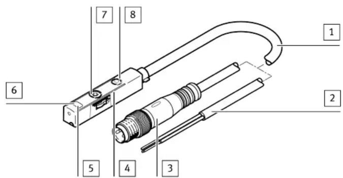
1 Connecting cable
2 Open cable end (SDBT-MSX-...-LE)
3 Plug connector M8
(SDBT-MSX-...-M8)
4 Marking of sensing range
5 Green LED: display of sensing range; only in teach-in mode
6 Yellow LED: switching status display
7 Retaining screw
8 Capacitive operating key
Fig. 1
3.2 Function
The proximity sensor SDBT-MSX detects the magnetic field of the piston magnet. In the sensing range of the proximity switch, a switching point can be programmed. To set a switching point in the sensing range of the proximity sensor, there are two options:
- Auto teach-in
– Capacitive operating key
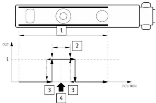
1 Sensing range
2 Switching window
Fig. 2
3 Hysteresis
4 Teach-in point
4 Installation
4.1 Electrical
WARNING!
Risk of injury due to electric shock.
- For the electrical power supply, use only PELV circuits in accordance with IEC 60204-1/EN 60204-1 (Protective Extra-Low Voltage, PELV).
- Observe the general requirements of IEC 60204-1/EN60204-1 for PELV circuits.
- Only use voltage sources that ensure a reliable electric separation from the mains network in accordance with IEC 60204-1/EN 60204-1.
Circuit diagrams
- Mount the proximity sensor in the end position of the piston so that the end position is in the sensing range of the sensor. If available, the orientation aid provides the marking of the piston end position on the drive.
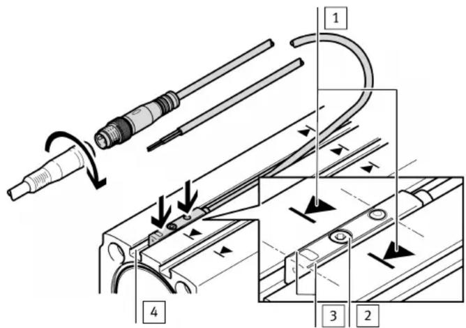
1 Marking of the piston end position on the drive (if available)
2 Retaining screw
Fig. 3
3 Marking of sensing range
4 T-slot
5 Commissioning
5.1 Automatic switching point setting: auto teach-in
Prerequisite: proximity sensor is in delivery status.
-
Mount the proximity sensor roughly in the end position→ 4.2 Mechanical.
-
Connect the proximity sensor→ 4.1 Electrical.
Proximity sensor is automatically taught in during operation, e. g. upon initial commissioning of the complete system.
Application notes on auto teach-in
During auto teach-in, each > 100 ms stop of the piston within the sensing range is output as a switching point. If the piston at this position reverses its direction of movement and leaves the sensing range without further stops, this switching point is saved temporarily.
If the piston stops 4x consecutively at the same position, reverses its direction of movement and leaves the sensing range without further stops, this position is saved as a final switching point. Auto teach-in is complete.
The process described corresponds with the classic use case: proximity sensor query at the end stop of the piston stroke or at the end stop of the customer application.
If the piston stroke is smaller than the sensing range of the SDBT-MSX, ensure that the second reversal point of the piston is outside the sensing range during auto teach-in → Tab. 3.
Application notes on auto teach-in
| Auto teach-in possible:End position A | Auto teach-in possible:End position B | Auto teach-in not possible. The switching point must be set using the capacitive operating key. |
Tab. 3
5.2 Manual operation using capacitive operating key
i
The proximity sensor is parameterised once it is installed.
- Be mindful of the surface temperature of the capacitive operating key and of the drive.
- Avoid contamination and moisture on the proximity sensor.
5.2.1 Setting the switching point
- Move the piston into the sensing range of the proximity sensor.
- Actuate the capacitive operating key 3 times to activate set-up mode.
- Actuate the capacitive operating key once to switch to the menu item "Set switching point".
- Actuate the capacitive operating key once.
The current piston position is taught in as the switching point.
5.2.2 Setting the switching point with variable switching window width
- Move the piston into the sensing range of the proximity sensor.
- Actuate the capacitive operating key 3 times to activate set-up mode.
- Actuate the capacitive operating key twice to switch to the menu item "Set switching point with variable switching window width".
- Actuate the capacitive operating key once.
The current piston position is taught in as a switching point with approx. 2 mm switching window width.
Every other keystroke increases the switching window width by approx.
1 mm. A max. switching window width of 15 mm is possible.
5.2.3 PNP/NPN switch-over
- Actuate the capacitive operating key 3 times to activate set-up mode.
- Actuate the capacitive operating key 3 times to switch to the menu item "Switch over between PNP / NPN".
- Actuate the capacitive operating key once to switch between PNP->NPN or NPN->PNP.
5.2.4 NO/NC switch-over
- Actuate the capacitive operating key 3 times to activate set-up mode.
- Actuate the capacitive operating key 4 times to switch to the menu item "Switch over between NO / NC".
- Actuate the capacitive operating key once to switch between NO->NC or NC->NO.
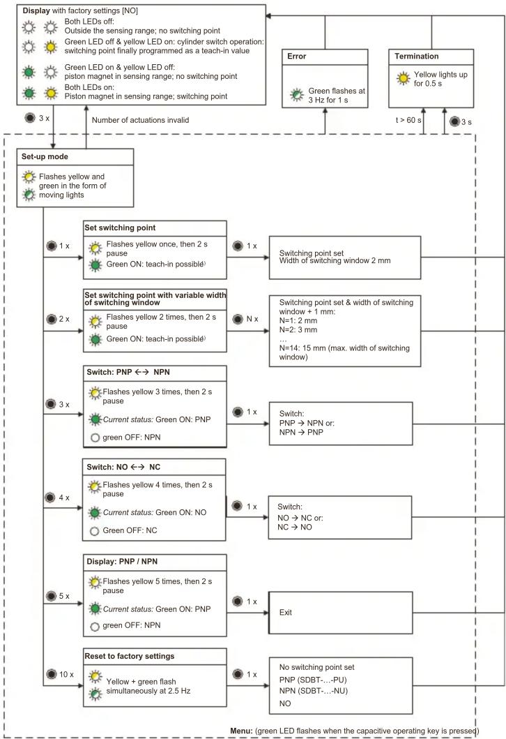
5.3 Menu structure
flowchart
graph TD
    A["Display with factory settings [NO"]
    Both LEDs off: Outside the sensing range; no switching point
    Green LED off & yellow LED on: cylinder switch operation: switching point finally programmed as a teach-in value
    Green LED on & yellow LED off: piston magnet in sensing range; no switching point
    Both LEDs on: Piston magnet in sensing range; switching point] --> B["Set up mode"]
    B --> C["Set switching point"]
    C --> D["1 x"]
    D --> E["Flashes yellow once, then 2 s pause"]
    D --> F["Green ON: teach-in possible¹"]
    E --> G["Switching point set Width of switching window 2 mm"]
    F --> H["Set switching point with variable width of switching window"]
    H --> I["2 x"]
    I --> J["Flashes yellow 2 times, then 2 s pause"]
    I --> K["Green ON: teach-in possible¹"]
    J --> L["N x"]
    K --> M["N=14: 15 mm (max. width of switching window)"]
    L --> N["Switching point set & width of switching window + 1 mm:<br>N=1: 2 mm<br>N=2: 3 mm<br>..."]
    M --> O["..."]
    N --> P["Switch: PNP ↔ NPN"]
    O --> Q["Switch: PNP → NPN or: NPN → PNP"]
    Q --> R["3 x"]
    R --> S["Switch: NO ↔ NC"]
    S --> T["4 x"]
    T --> U["Switch: NO → NC or: NC → NO"]
    U --> V["5 x"]
    V --> W["Display: PNP / NPN"]
    W --> X["6 x"]
    X --> Y["Flashes yellow 5 times, then 2 s pause"]
    X --> Z["Current status: Green ON: PNP<br>green OFF: NPN"]
    Y --> AA["10 x"]
    AA --> AB["Reset to factory settings"]
    AB --> AC["Yellow + green flash simultaneously at 2.5 Hz"]
    AC --> AD["No switching point set PNP (SDBT-...-PU)<br>NPN (SDBT-...-NU)<br>NO"]
    AD --> AE["t > 60 s"]
    AE --> AF["Error"]
    AF --> AG["Green flashes at 3 Hz for 1 s"]
    AG --> AH["Termination"]
    AH --> AI["Yellow lights up for 0.5 s"]
    AI --> AJ["3 s"]
N x = press capacitive operating key (e.g.: 3 x);
Max. 1 second pause between two consecutive presses. After a 1 second pause, entry is copied.
3 s = hold the capacitive operating key pressed for at least 3 seconds
= LED ON / LED flashes / LED OFF (e.g.: yellow LED)
1) A switching point can only be set when the green LED is ON.
When the green LED is flashing at 1.5Hz, the magnet is located in the region of the function reserve. It is not possible to set a switching point. The function reserve is required for the safe setting of switching points in the edge region. When the green LED is OFF, the magnet is outside the sensing range. It is not possible to set a switching point.
Fig. 4
6 Reset to factory settings.
| Parameter Factory setting | |
| Operating mode Auto teach-in | |
| Switching output No switching point programmed | Configuration of the switching output:– SDBT- ... -PU: PNP– SDBT- ... -NU: NPNSwitching element function: NO |
| Variable switching window width Not programmed |
Tab. 4
- Actuate the capacitive operating key 3 times to activate set-up mode.
- Actuate the capacitive operating key 10 times to switch to the menu item "Reset to factory settings".
- Actuate the capacitive operating key once.
→ Proximity switch is reset to factory settings.
7 Malfunctions
7.1 Diagnostics via LEDs
| Display Meaning Measure | ||
| off | Status indication:– Piston outside the sensing range– Piston not at switching point | Normal operating caseBoth LEDs |
| Error:– Power supply fault– Connecting cable or sensor defective | – Check power supply– Check connecting cable– Replace device | |
| Green LED flashes at 6 Hz | Hardware error – Disconnect and connect proximity sensor– Replace device | |
Tab. 5
7.2 General malfunctions
| Error description Possible cause Measures/remedy | ||
| Incorrect or unexpected signals at the output | Proximity sensor defective – Replace proximity sensor | |
| Operating voltage not connected or outside the operating voltage range | – Comply with operating voltage range | |
| Short circuit or overload at the output | – Rectify short circuit/over-load | |
| Magnetic or ferromagnetic objects close to the proximity sensor | – Keep magnetic or ferromagnetic objects clear of the proximity sensor– Conditions during teach-in of the switching point must correspond to operating conditions (e.g. no screwdriver in the locking screw) | |
| Orientation of the proximity sensor rotated 180° in the slot after adjustment of the switching point | – Reset switching point (with auto teach-in or operating key) | |
| react in accordance with the settings | Proximity sensor defective – Replace proximity sensorSwitching output does not | |
| Short circuit or overload at the output | – Rectify short circuit/over-load | |
| Capacitive operating key does not react to input | Dirt or moisture on the proximity sensor | – Wipe proximity sensor with a dry cloth |
Tab. 6
8 Technical data
| SDBT-MSX | |
| Operating voltage range [V DC] 10 ... 30 | |
| Max. output current [mA] 100 | |
| Operating temperature range [°C]−40 ... +85 (UL: +80) | |
| Ambient temperature with [°C]−20 ... +85 (UL: +80)flexible cable installation | |
| Degree of protection(EN 60529) | IP 65 / IP 68 |
Tab. 7
- Further applicable documents
- Safety
- Intended use
- Area of application and approval
- Tab. 1
- Product overview
- Structure
- Function
- Installation
- Electrical
- WARNING!
- Risk of injury due to electric shock.
- Commissioning
- Automatic switching point setting: auto teach-in
- Application notes on auto teach-in
- Manual operation using capacitive operating key
- Setting the switching point
- Setting the switching point with variable switching window width
- PNP/NPN switch-over
- NO/NC switch-over
- Menu structure
- Fig. 4
- Tab. 4
- Malfunctions
- Diagnostics via LEDs
- General malfunctions
- Technical data
Brand : Festo
Model : SDBT-MSX-1L-NU-E-2.5-N-LE
Category : Detector