
Eco Pro GE-12 - Water heater Guardian - Free user manual and instructions
Find the device manual for free Eco Pro GE-12 Guardian in PDF.


| Type | Electric storage water heater |
| Model | Eco Pro GE-12 |
| Brand | Guardian |
| Capacity | 50 liters (approx. 12 gallons) |
| Dimensions (H x W x D) | 600 x 450 x 450 mm |
| Weight (empty) | 20 kg |
| Power rating | 2000 W |
| Voltage | 220-240 V / 50 Hz |
| Energy efficiency class | C |
| Max water temperature | 75°C |
| Inlet/Outlet connection | 1/2 inch BSP |
| Inner tank material | Enamel-coated steel |
| Insulation | High-density polyurethane foam |
| Anode | Magnesium sacrificial anode |
| Safety features | Thermostat, overheat protection, pressure relief valve |
| Installation | Wall-mounted, requires professional installation |
| Maintenance | Annual anode inspection, periodic flushing |
| Warranty | 2 years on tank, 1 year on parts |
Frequently Asked Questions - Eco Pro GE-12 Guardian
User questions about Eco Pro GE-12 Guardian
0 question about this device. Answer the ones you know or ask your own.
Ask a new question about this device
Download the instructions for your Water heater in PDF format for free! Find your manual Eco Pro GE-12 - Guardian and take your electronic device back in hand. On this page are published all the documents necessary for the use of your device. Eco Pro GE-12 by Guardian.
USER MANUAL Eco Pro GE-12 Guardian
natural_image
Stylized logo of a helmet with teal and dark blue colors (no text or symbols)GUARDIAN
— POOL HEATING —

natural_image
Front view of a black industrial fan with blue blades and a control panel (no visible text or symbols)ECOPRO SERIES
INVERTER POOL & SPA HEAT PUMP
4.2.8 FAULT INTERFACE....11
4.3 TROUBLESHOOTING GUIDE....12
5.1 INTRODUCTION....14
5.2 INSTALLATION....14
5.3 APP SETUP....15
5.3.1 CREATE AN ACCOUNT 15
5.3.2 ADD YOUR DEVICE & CONFIGURE WI-FI....15
5.3.3 DEVICE MANAGEMENT....17
6. MAINTENANCE & INSPECTION....19
7. APPENDIX....23
7.1 CABLE SPECIFICATIONS....23
7.2 REFRIGERANT SATURATION TEMPERATURE 23
7.3 INTERFACE DIAGRAMS....23
7.4 WIRING DIAGRAMS......25
7.5 WARRANTY TERMS....28
BEFORE YOU BEGIN
1 Ensure that the heat pump arrives in good condition upon delivery.
2 Adequate airflow around the heat pump is vital, ensure that the surroundings are kept clear of debris, tree branches and anything that might impact the ventilation of the unit. Refer to Section 3.2 of this manual for more information.
3 Register your unit's warranty details and upload your invoice online at: www.guardianpoolheating.com.au/
4 Your unit should be installed in an outdoor area for maximum performance, for indoor installations contact Guardian for guidance.
5 Check the condensate drain of the heat pump regularly to avoid blockages or debris build up. Keeping it in good order ensures condensation easily drains from the unit.
6 When using Wi-Fi control, ensure that you have full Wi-Fi strength available where the heat pump is installed. You will require a 2.4gHZ connection to use the Wi-Fi Controller App.
1. FOREWARD
Congratulations on purchasing your Guardian EcoPro high efficiency inverter pool heat pump!
Guardian heat pumps are designed and built to the highest industry standard and are backed by our extended warranty service for peace of mind.
A warranty registration is highly recommended to be submitted online at: www.guardianpoolheating.com.au
Ensure all information contained within this manual is read and fully understood before attempting to install or operate the pool heat pump.
If technical support or further information is required please contact support@guardianpoolheating.com.au
We trust you'll have a longer and more enjoyable time in your pool with your Guardian heat pump!
Thank you!
1.1 WARNINGS
Please read this manually carefully before installing or operating the unit. The unit must only be installed by a qualified professional.
- The unit must be installed in accordance with national wiring regulations.
• Before obtaining access to terminals, all supply circuits must be disconnected. - An all-pole disconnection device must be incorporated which as at least 3mm clearances in all poles, a leakage current that may exceed 10mA, residual current device (RCD) having a rated residual operating current not exceeding 30mA and disconnection must be incorporated in the fixed wiring in accordance with the wiring rules.
- Do not accelerate the defrosting process or clean the unit in any way that is not recommended in this manual.
- Do not store the unit in a room with continuously operating ignition sources, or install near any flammable gas.
• Do not pierce or burn the unit.
• Make sure the unit has good earthing and power connection to reduce the risk of electric shock. - If the supply cord is damaged it must be replaced by the supplier to avoid hazards occurring.
- Ensure there is a circuit breaker for the unit to avoid electric shock or fires.
• Use supply wires suitable for 75°C - The unit is equipped with an over-load protection system. It does not allow for the unit to start for at least 3 minutes from a previous stoppage.
- Be aware that refrigerants may not contain an odour.
• The installation of pipe-work should be kept to a minimum 30m^2 - Caution: Single wall heat exchanger, not suitable for a potable water connection.
• Directive 2002/96/EC (WEEE):
The symbol depicting a crossed-out waste bin that is underneath the appliance indicates that this product, at the end of its useful life, must be handled separately from domestic waste, or must be taken to a recycling centre for electric and electronic devices.
• Directive 2002/95/EC (RoHs):
This product is compliant with directive 2002/95/EC (RoHs) concerning restrictions for the use of harmful substances in electric and electronic devices
Information in this manual is correct at the time of publishing and while the information is correct at the date of publication, changes in circumstances after the time of publication may impact on the accuracy of the information. The information may change without notice and Guardian is not in any way liable for the accuracy of any information printed and stored or in any way interpreted and used by a user.
2. SPECIFICATIONS
2.1 PERFORMANCE DATA
| GE-9 | GE-12 | GE-16 | GE-20 | GE-24 | GE-28T | ||
| Heating Capacity (27/24.3°C) | kW | 2.3~9.0 | 2.5~12.0 | 3.1~16.0 | 3.70~20.0 | 6.5~24.3 | 7.1~28.2 |
| Btu/h | 7820~30600 | 8500~40800 | 10540~54400 | 12580~68000 | 22100~82620 | 24140~95880 | |
| Heating Power Input | kW | 0.16~1.41 | 0.18~1.90 | 0.22~2.54 | 0.27~3.22 | 0.45~3.74 | 0.49~4.41 |
| C.O.P | 14.2~6.4 | 14.1~6.3 | 13.9~6.3 | 13.8~6.2 | 14.5~6.5 | 14.3~6.4 | |
| Heating Capacity (15/12°C) | kW | 1.7~7.0 | 2.1~9.0 | 2.4~12.6 | 2.6~14.5 | 4.5~19.0 | 5.1~21.0 |
| Btu/h | 5780~23800 | 7140~30600 | 8160~42840 | 8840~49300 | 15300~64600 | 17340~71400 | |
| Heating Power Input | kW | 0.24~1.46 | 0.29~1.91 | 0.34~2.73 | 0.38~3.15 | 0.62~3.88 | 0.71~4.38 |
| C.O.P | 7.2~4.8 | 7.1~4.7 | 7.0~4.6 | 6.9~4.6 | 7.3~4.9 | 7.2~4.8 | |
| Power Supply | 220-240/1/50 | 380-415/3/50 | |||||
| Connection Type | 10amp | 10amp | 15amp | hardwired | hardwired | hardwired | |
| Compressor Quantity | 1 | 1 | 1 | 1 | 1 | 1 | |
| Compressor Type | rotary | rotary | rotary | rotary | rotary | rotary | |
| Fan Number | 1 | 1 | 1 | 1 | 1 | 1 | |
| Fan Power Input | W | 40 | 40 | 40 | 40 | 40 | 40 |
| Fan Rotate Speed | RPM | 400-800 | 400-800 | 400-800 | 300-750 | 300-750 | 300-750 |
| Fan Direction | horizontal | horizontal | horizontal | horizontal | horizontal | horizontal | |
| Noise (1M) | dB(A) | 39-50 | 41-52 | 42-53 | 43-54 | 49-56 | 47-55 |
| Water Connection | mm | 40 | 40 | 40 | 40 | 40 | 40 |
| Flow Rate | L/min | 53 | 67 | 87 | 100 | 173 | 200 |
| Water Pressure Drop (max) | kPa | 4.0 | 3.0 | 4.0 | 5.0 | 10.4 | 12.0 |
| Net Dimensions (LxWxH) | mm | 999 x 418 x 605 | 1044 x 453 x 768 | 1158 x 467 x 862 | 1159 x 490 x 858 | ||
*Please note: Information is correct at the time of printing and may be liable to change at any time without notice.
Heating: Outdoor air temp: 27°C/24.3°C
Inlet water temp: 26°C
Outdoor air temp: 15°C/12°C
Inlet water temp: 26°C
Operating Range: Ambient Temperature: -7-43°C
Water temperature: 9-40°C
ECOPRO SERIES
Note: Diagram is for reference only.
The Heat Pump can be installation can be configured with a bypass system to enable operation of the filtration and sanitation systems to continue while the heat pump is not in use.
Upon receiving your unit you will also receive 1x Instruction Manual, 2x Connectors, 2x Rubber Rings & 4x Rubber Feet.
When using the unit for the first time:
- Open the water valves.
• Make sure that the pump and the water-in pipe have been filled with water. - Close the valve and start the unit.
Note: It is necessary that the water-in pipe is higher than the pool's surface.
3.2 LOCATION OF INSTALLATION
Note: as per the diagram, you need to have clearances of: 1500mm at the front, 300mm at the rear, 500mm at the top of the unit, and 700mm on both sides.
DO NOT place the unit in an enclosed area or room to prevent the discharge air being recirculated.
DO NOT place the unit near shrubs that may grow and block the air inlet.
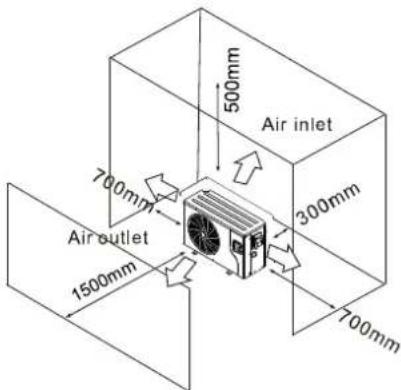
Placing the unit in a location where the unit is denied a continuous source of fresh air will reduce efficiency and may prevent adequate heat delivery.
The heat pump should be installed as close as possible to filtration equipment. The longer the distance from the pool, the greater the heat loss from the piping.
Majority of the piping is usually buried, therefore the heat loss is minimal for runs of up to 15 metres (each way, 30 in total) unless the ground is wet or the water table is high. A very rough estimate of heat loss per 30 metres is 0.6kW an hour for every 5°C difference in temperature between the pool water and the ground surrounding the pipe, translating to roughly 3% to 5% increase in run time.
3.3 PLUMBING OF THE UNIT
The titanium heat exchanger of the unit requires no special plumbing arrangements. The water pressure drop is less than 10kPa at maximum flow rate. Since there is no residual heat or flame temperatures, the unit doesn't require copper heat sink piping. PVC pipe can be ran straight into the unit.

LOCATION: Connect the unit in the pool pump discharge (return) line downstream of all filter and pool pumps, and upstream of any chlorinators, ozonators or chemical pumps.
Standard models have slip glue fittings which accept 40mm or 50mm PCV pipe for connection to the pool or spa filtration plumbing. By using a 50mm to 40mm reducer you can plumb 40mm.
CONDENSATION: Since the heat pump cools down the air from 4-5°C, water may condense on the fins of the evaporator. If the relative humidity is very high, this could be multiple litres per hour. The water will run down the fins into the basepan and drain our through the barbed plastic condensation drain fitting on the side of the basepan. This fitting is designed to accept 20mm clear vinyl tubing which can be pushed on by hand and ran to a suitable drain. It is very easy to mistake the condensation for a leak inside the unit.
NB: A quick way to determine if the water is condensation is to shut off the unit while keeping the pool pump running. If water stops running out of the basepan then it is condensation. Another way is to test the drain water for chlorine, if there is no chlorine present then it is condensation.
3.4 ELECTRICAL WIRING
Note: Although the unit's heat exchanger is electrically isolated from the rest of the unit, it simply prevents the flow of electricity to or from the pool water. Grounding the unit is still required to protect you against short circuits inside the unit. Bonding is also required.
The unit has a separate molded-in junction box with a standard electrical conduit nipple already in place. Just remove the screws and the front panel, feed your supply lines in through the conduit nipple and wire-nut the electric supply wires to the three connections already in the junction box (four connections if three phase). To complete the electrical hookup, connect the heat pump by electrical conduit, UF cable or another suitable means as specified (as permitted by local electrical authorities) to a dedicated AC power supply branch circuit equipped with the proper circuit breaker, disconnect or time delay fuse protection.
DISCONNECT: A disconnect means (circuit breaker, fused or un-fused switch) should be located within sight of and readily accessible from the unit. This is common practice on commercial or residential air conditioners and heat pumps. It prevents remotely-energising unattended equipment and permits turning off power at the unit while it is being serviced.
3.5 FIRST TIME STARTUP
Note: In order for the unit to heat the pool or spa the filter pump must be running to circulate water through the heat exchanger.
STARTUP PROCEDURE
(After installation has been completed follow these steps)
- Turn on the filter pump. Check for water leaks and verify flow to and from the pool.
- Turn on the electrical power supply to the unit, then press the ON/OFF key on the controller. The unit should start within a few seconds.
- After running for a few minutes ensure the air leaving the unit is cooler (between 5-10°C)
- With the unit operating turn the filter pump off. The unit should also turn off automatically.
- Allow the unit and pool pump to run 24hrs per day until the desired water temperature is reached at which point the compressor will slow down to maintain temperature.
TIME DELAY
The heat pump is equipped with a time delay, this prevents the unit from short cycling. The fan will always start first, followed by the compressor.
4. USE & OPERATION
4.1 THE CONTROL PANEL

| POWER | Start or shut down the unit, cancel the current operation, return to the previous menu. | |
| MODE | Switch between unit modes, temperature settings & parameter settings. | |
| CLOCK | User clock & timer settings. | |
| SILENT | Turn on or off the silent function OR set a silent timer function. | |
| UP | Scroll up or increase value. | |
| DOWN | Scroll down or decrease value. |
Icons Explained
| Cooling | Displays during cooling | Out | Water outlet | Water outlet temperature | |
| Heating | Displays during heating | In | Water inlet | Water inlet temperature | |
| Automatic | Displays under auto mode | Lock | Displays when keyboard is locked | ||
| Defrosting | Displays during defrosting | Fault | Displays when a fault occurs | ||
| Silent | Indicates silent status | Degrees | Indicates temperature in Celsius | ||
| OFF 1ON 2 | Timing | Timing periods that can be set | Set | Setting | Parameter is adjustable |
4.2 USING THE CONTROL PANEL
4.2.1 ON/OFF MODE
The heat pump will display 'OFF' on the screen while the unit is not turned on. When it has been turned on, the water inlet temperature is displayed on the screen.
Simply press the POWER button for half a second to turn the unit on or off.
4.2.2 SWITCHING MODES
Cooling Auto Heating


From the main menu, press the MODE button to switch the unit among heating, cooling and automatic mode.
The mode change will automatically save after 2 seconds of idle operation.
Note: When the unit is in Defrosting mode, the defrosting symbol will appear on the screen. Upon completing the defrosting, the unit automatically switches to heating/automatic mode.
4.2.3 SMART, BOOST & ECO MODES
Under either the Cooling or Heating modes, there are 3 different 'sub-modes' of frequency operation.
- Smart mode will automatically choose whether the unit needs to run in boost or eco modes.
- Boost mode will get your unit to the target temperature faster.
- Eco mode will run the unit at a reduced rate to save power consumption. It may take slightly longer to reach the target temperature.
To enter the sub-modes menu, first ensure you are on either Cooling or Heating mode on the main screen. Press and hold the DOWN (-) button for 3 seconds to enter the sub-menu.
A screen will appear with one of the following symbols: b (Boost), 5 (Smart), E (Eco). Use the UP (+) and DOWN (-) keys to select the desired mode. To save the mode setting, either leave the screen idle for 5 seconds or press the MODE button. Press the POWER button to cancel changes and return to the main menu.

Boost Mode

Smart Mode

Eco Mode
4.2.3 SETTING THE TEMPERATURE

Press the CLOCK button
Use UP & DOWN to adjust the temperature

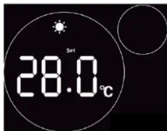
To change the set temperature of the unit, simply press the UP or DOWN key. The set temperature will begin to flash when you are altering it. Use the keys to adjust the temperature as required, then let the screen sit idle for 5 seconds to save the changes.
4.2.4 CLOCK SETTINGS
To change the system time of the unit, press the CLOCK button, the time will appear.
To set the hour digit, press the CLOCK button. The hour value will begin to flash indicating it is currently being edited. Use the + or - keys to adjust the hour value, then press CLOCK to save and move onto the minute value.
When the minute value is flashing, press the + or - arrows again, pressing CLOCK and then POWER again to save your changes.

Press CLOCK

natural_image
Digital clock display showing 08:00 with two white circles on a dark background (no text or symbols beyond time and circle)Press CLOCK The hour will begin to flash

natural_image
Digital clock display showing 18:00 with two white circles on a dark background (no text or symbols beyond time and circle)Adjust the hour then press CLOCK to adjust minute

Adjust minutes then press CLOCK then POWER to save
4.2.5 TIMER SETTINGS
4.2.5.1 SETTING ON/OFF TIMER

Hold CLOCK to enter timer settings

natural_image
Two white circles on a black background with a dashed scale bar labeled '1 ON' (no text or symbols beyond the label)Select a timer using the arrow keys, then CLOCK to adjust time.

natural_image
Digital clock display showing 18:00' with two white circles on a dark background (no text or symbols beyond clock and circle)The hour digit will be flashing indicating is changeable

Use arrow keys to adjust hour, then CLOCK to save and adjust minutes.
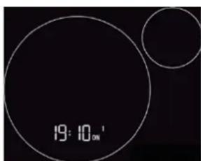
The hour digit will now be flashing indicating is changeable.
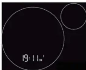
Adjust the minutes then press CLOCK to finish setting timer. Press CLOCK again to save and head back to main menu.
Note: 2 different timer periods can be set (ON1-OFF1 & ON2-OFF2).
If you wish to set a timer for your unit, you first need to enter into the CLOCK setting interface by pressing the CLOCK button once. To then enter into the timer setting menu, hold the CLOCK button for 2 seconds.
You will enter the beginning of the timer menu where you can first select which timer you would like to set. Use the arrow keys to select from ON1, OFF1, ON2 or OFF2.
Once you have selected the timer you wish to edit, press the CLOCK button.
Use the UP and DOWN keys to adjust the hour value, then press the CLOCK button to edit the minute value. Once you have set the minute value, press the CLOCK button to save the selected timer. To exit the timer menu, press the CLOCK button a final time.
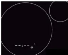
In the timer setting interface, with either the hour or minute digit flashing, press the POWER button to cancel the setting.

natural_image
Abstract diagram with two large circles and a horizontal scale labeled '1', set against a dark background (no text or symbols beyond the scale)With hour or minute digit flashing, press POWER to cancel timer.
4.2.6 SILENT SETTINGS
4.2.6.1 SETTING A SILENT TIMER
From the main menu, press and hold the SILENT key for 2 seconds. This menu will allow you to set a single timing period of reduced noise from the unit.
Using the same method as adjusting the on/off timers, you can set an on & off time.
Note: Only the start and end hour can be set.
4.2.6.2 ONE-CLICK SILENT
Press the SILENT button to enable or disable the silent function. When the silent function is enabled, the icon on the screen will display with 3 blades (When the function is not on, the fan appears with all blades).


Silent Mode OFF Silent Mode ON
4.2.7 KEYBOARD LOCK
To lock or unlock the controller simply hold the POWER button for 5 seconds. A small lock symbol will appear and flash on the main screen when the unit is locked.
4.2.8 FAULT INTERFACE
If a failure occurs, the controller will display a code that corresponds to a specific error. Refer to the fault table for definitions of the fault codes.
If multiple failures occur at once, use the UP or DOWN keys to scroll between them.
To minimise the fault window and view the main menu, press the POWER button once.

1 Quantity of fault/s
2 Fault serial number
3 Fault code
4.3 TROUBLESHOOTING GUIDE
Electronic Control Fault Table
| Malfunction Display | Cause Solution | ||
| Inlet temp. sensor fault | P01 | The temp. sensor is broken or short circuit | Check or change the temp. sensor |
| Outlet temp. sensor Fault | P02 | The temp. sensor is broken or short circuit | Check or change the temp. sensor |
| Ambient temp. sensor Fault | P04 | The temp. sensor is broken or short circuit | Check or change the temp. sensor |
| Coil 1 temp. sensor fault | P05 | The temp. sensor is broken or short circuit | Check or change the temp. sensor |
| Coil 2 temp. sensor fault | P15 | The temp. sensor is broken or short circuit | Check or change the temp. sensor |
| Suction temp. sensor Fault | P07 | The temp. sensor is broken or short circuit | Check or change the temp. sensor |
| Discharge temp. sensor Fault | P081 | The temp. sensor is broken or short circuit | Check or change the temp. sensor |
| Exhaust air over temp prot. | P082 | The compressor is overload | Check whether the system of the compressor running normally |
| Antifreeze temp. sensor fault | P09 | Antifreeze temp sensor is broken or short circuited | Check and replace this temp sensor |
| Pressure sensor fault | PP | The pressure sensor is broken | Check or change the pressure Sensor or pressure |
| High pressure prot. | E01 | The high-pressure switch is broken | Check the pressure switch and cold circuit |
| Low pressure prot. | E02 | Low pressure1 protection | Check the pressure switch and cold circuit |
| Flow switch prot. | E03 | No water/little water in water system | Check there is water flow to pool. If there is flow, flow switch needs changing |
| Waterway anti-freezing prot. | E05 | Water temp. or ambient temp. is too low | |
| Inlet and outlet temp. too big | E06 | Water flow is not enough and low differential pressure | Check the pipe water flow and whether water system is jammed or not |
| Anti-freezing prot. | E07 | Water flow is not enough | Check the pipe water flow and whether water system is jammed or not |
| Primary anti-freezing prot. | E19 | The ambient temp. is low | |
| Secondary anti-freezing prot. | E29 | The ambient temp. is low | |
| Comp. overcurrent prot. | E051 | The compressor is overload | Check whether the system of the compressor running normally |
| Communication fault | E08 | Communication failure between wire controller and mainboard | Check the wire connection between remote wire controller and main board |
| Communication fault (speed control module) | E081 | Speed control module and main board communication fail | Check the communication connection |
| Low AT protection | TP | Ambient temp is too low | |
| EC fan feedback fault | F051 | There is something wrong with fan motor and fan motor stops running | Check whether fan motor is broken or locked or not |
| Fan motor1 fault | F031 | Motor is in locked-rotor state The wire connection between DC-fan motor module and fan motor is in bad contact | Change a new fan motor Check the wire connection and make sure they are in good contact |
| Fan motor2 fault | F031 | Motor is in locked-rotor state The wire connection between DC-fan motor module and fan motor is in bad contact | Change a new fan motor Check the wire connection and make sure they are in good contact |
Frequency Conversion Board Fault Table
| Protection/fault | Fault display | Reason Elimination methods | |
| Drv1 MOP alarm | F01 | MOP drive alarm | Recovery after the 150s |
| Inverter offline | Frequency conversion board and mainboard communication failure | Check the communication connection | |
| IPM protection | F03 | IPM modular protection | Recovery after the 150s |
| Comp. driver failure | F04 | Lack of phase, step or drive hardware damage | Check the measuring voltage check frequency conversion board hardware |
| DC Fan fault | Motor current feedback open circuit or short circuit | Check whether current return wires connected motor | |
| IPM Overcurrent | F06 | IPM Input current is large | Check and adjust the current measurement |
| Inv. DC Overvoltage | F07 | DC bus voltage>Dc bus over-voltage protection value | Check the input voltage measurement |
| Inv. DC Less voltage | F08 | DC bus voltage< Dc bus over-voltage protection value | Check the input voltage measurement |
| Inv. input less volt. | F09 | The input voltage is low, causing the input current is high | Check the input voltage measurement |
| Inv. input overvolt. | F10 | The input voltage is too high, more than outage protection current RMS | Check the input voltage measurement |
| Inv. Sampling Volt. | F11 | The input voltage sampling fault | Check and adjust the current measurement |
| Comm. Err DSP-PFC | F12 | DSP and PFC connect fault | Check the communication connection |
| Input Over Cur. | F26 | The equipment load is too large | |
| PFC fault | F27 | The PFC circuit protection | Check the PFC switch tube short circuit or not |
| IPM overheating | F15 | The IPM module is overheat | Check and adjust the current measurement |
| Weak magnetic warn | F16 | Compressor magnetic force is not enough | |
| Inv. input out phase | F17 | The input voltage lost phase | Check and measure the voltage adjustment |
| IPM sampling cur. | F18 | IPM sampling electricity is fault | Check and adjust the current measurement |
| Inv. temp. probe Fail | F19 | Sensor is short circuit or open circuit | Inspect and replace the sensor |
| Inverter overheating | F20 | The transducer is overheat | Check and adjust the current measurement |
| Inv. overheating warn | F22 | Transducer temperature is too high | Check and adjust the current measurement |
| Comp. over cur. warn | F23 | Compressor electricity is large | The compress or over-current protection |
| Input Over Cur. Warn | F24 | Input current is too large | Check and adjust the current measurement |
| EEPROM Error Warn | F25 | MCU error | Check whether the chip is damagedReplace the chip |
| V15V over/undervoltage fault | F28 | The V15V is overload or under-voltage | Check the V15V input voltage in range 13.5v~16.5v or not |
5. WI-FI OPERATION
5.1 INTRODUCTION
The Guardian Handy Heat Pump app is available as a standard inclusion on the Guardian Lux-V, Platinum & EcoPro series.
Available for iOS and Android, the smart phone controller app offers you an easy and convenient way to monitor and control your pool temperature, as well as adjust settings, set timers, receive error alerts & allow remote access from a technician.
Module Diagram
| NAME | LONG LIGHT | SLOW FLASH | |
| 1 | Network configuration indicator | Configuring Network | SmartLink configuring |
| 2 | Router connection indicator | Normal | Abnormal |
| 3 | Cloud server connection indicator | Normal | Abnormal |
| 4 | 485 communication indicator | Normal | Abnormal |
5 Configuration button

Troubleshooting:
Ensure that you are connecting to a 2.4GHZ network, not a 5GHZ network. If you are unsure, contact your network provider.
Ensure you are not connecting to a Wi-Fi booster or extender, connection must be made to the modem directly.
Check signal strength and distance between the heater and the modem is not more than 10m. If possible, try moving your modem closer to test the connection.
(If issues occur) Try using a different mobile device with a different software version to ensure you have no compatibility issues.
5.2 INSTALLATION
There is a magnet on the back on the wi-fi module which holds it in place on the heat pump. Where possible, the module should be placed on the unit in a location where it receives the least direct sunlight and away from other weather elements.
To download the app, head to your device's app store and search 'Handy Heat Pump' or scan the QR code below.
| APPLE ANDROID | |
 |  |
| CLICK HERE | CLICK HERE |
5.3 APP SETUP
5.3.1 CREATE AN ACCOUNT

Fig. 2: Home Page

Fig. 1: Login Menu

Fig. 3: Forgot Password Menu
- You need to create an account to use the app. To register, press the Account Registration button & fill in your details.
- Press the button next to 'Enter Email Verification' to send a code to your email (ensure you check your Junk folder). Once you have this code, go back into the app and enter the code into the field.
Set a new password for your account to finish registering your account.
Note: the verification code is only valid for 15 minutes, after this time you will need to request a new one.
- From the login page (Fig.1) enter your registered email and password and then press Login. If you forget your password, you can head to the Forgot Password screen and follow the prompts.
5.3.2 ADD YOUR DEVICE & CONFIGURE WI-FI
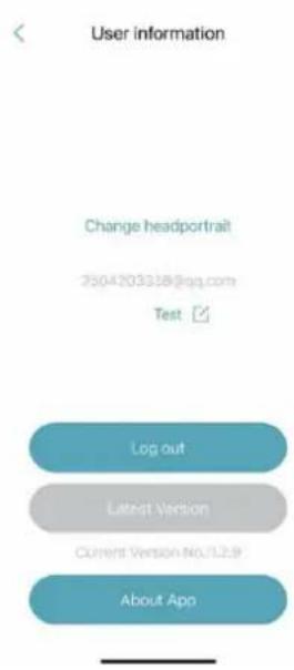
Fig. 5: Left-Hand Menu

Fig. 4: My Device Menu

Fig. 6: Add Device Menu
Once you have logged in, you will enter the My Device screen (Fig.4) where you can add your device and set up the wi-fi connection.
Note: ensure your Bluetooth is turned on in your phone settings and enabled in the app settings. The app will ask for permission to use Location, Camera & Bluetooth, ensure you always allow these as the app requires them to function.
- To add your device, press the + button in the top right corner and then select the BOTTOM Wi-Fi option (Fig. 6).
- Press and hold the button on the Wi-Fi module for a second until two lights turn on. This means the AP connection is activated and ready to connect. Press 'Next' (Fig. 7).
- Enter your home router's Wi-Fi password then press OK (ensure it is correct!). The app will now search for your device, you may need to sit near the heat pump during this process (Fig. 8-9)
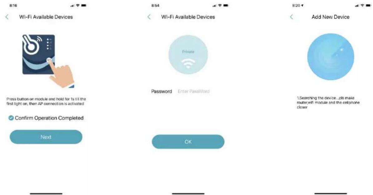
Fig. 7: Wi-Fi Module On Menu
Fig. 8: Enter Wi-Fi Password
Fig. 9: Searching for Device
- Once your device has been recognised (Fig. 10) you will then need to link your device using the barcode (Fig. 11 - 12). You can either use the camera to scan the barcode or enter it manually, the correct barcode will start with a WF.

Fig. 10: Device Bonded

Fig. 11: Manually Input Barcode

Fig. 12: Scan Barcode
- Once you have linked the correct barcode, you can complete the connection and name your device if required (e.g. Holiday Home Heater).
- Once complete, you will enter the device management menu (Fig. 14) where you can go into the unit to view and adjust the settings.

Fig. 13: Connection Complete

Fig. 14: Device Management

Fig. 15: Device Main Menu
5.3.3 DEVICE MANAGEMENT
Once Wi-Fi and Bonding has been completed, enter the 'My Device' menu to access a range of functions.
ICON NAME FUNCTIONS
 | ON/OFF | Turn the unit on or off |
 | SILENT MODE (OFF) | Silent mode is not activated |
 | SILENT MODE (ON) | Silent mode has been activated. |
 | COOLING | Cooling mode, press to select a different mode. |
 | HEATING | Heating mode, press to select a different mode. |
 | AUTO | Auto mode, press to select a different mode. |
 | TIMER SETTINGS | Adjust timer on/off & mute timer settings |

TROUBLESHOOTING View errors
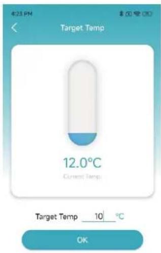
Fig. 16: Modify Target Temperature
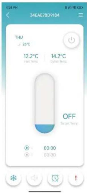
Fig. 17: Main Menu

Fig. 18: Right-Hand Menu

Fig. 19: Mode Menu
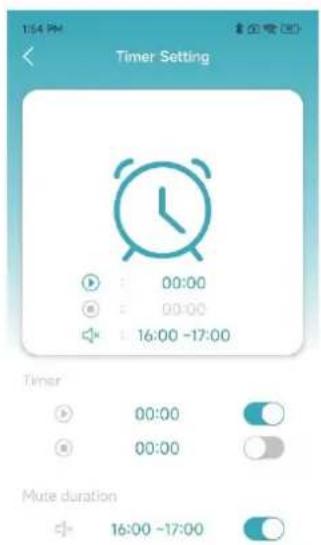
Fig. 20: Timer Settings
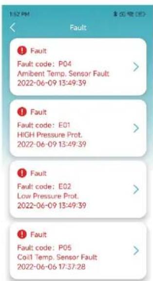
Fig. 21: Troubleshooting Menu
6. MAINTENANCE & INSPECTION
Check that the heat pump has good water flow. Avoid the condition of no water or air entering the system, this will influence unit's performance and reliability.
You should clear the pool/spa filter regularly to avoid damage to the unit as a result of the dirty or clogged filter.
The area around the unit should be dry, clean and well ventilated. Clean the side heating exchanger regularly to maintain good heat exchange.
The operation pressure of the refrigerant system should only be serviced by a certified technician.
Check the power supply and cable connection often, should the unit begin to operate abnormally, switch it off and contact a qualified technician.
CHECKS TO THE AREA
Prior to beginning work on systems containing flammable refrigerants, safety checks are necessary to ensure that the risk of ignition is minimised. For repair to the refrigerating system, the following precautions shall be complied with prior to conducting work on the system.
WORK PROCEDURE
Work shall be undertaken under a controlled procedure to minimise the risk of a flammable gas or vapour being present while the work is being performed.
GENERAL WORK AREA
All maintenance staff and others working in the local area shall be instructed on the nature of work being carried out. Work in confined spaces should be avoided. The area around the workspace should be sectioned off. Ensure that the conditions within the area have been made safe by control of flammable material.
CHECKING FOR PRESENCE OF REFRIGERANT
The area should be checked with an appropriate refrigerant detector prior to and during work, to ensure the technician is aware of potentially flammable atmospheres. Ensure that the leak detection equipment being used is suitable for use with flammable refrigerants, i.e. non-sparking, adequately sealed or intrinsically safe.
PRESENCE OF FIRE EXTINGUISHER
If any hot work is to be conducted on the refrigeration equipment or any associated parts, appropriate fire extinguishing equipment shall be available to hand. Have a dry powder or CO2 fire extinguisher adjacent to the charging area.
NO IGNITION SOURCES
No person carrying out work in relation to a refrigeration system which involves exposing any pipe work that contains or has contained flammable refrigerant shall use any sources of ignition in such a manner that it may lead to the risk of fire or explosion. All possible ignition sources, including cigarette smoking, should be kept sufficiently far away from the site of installation, repairing, removing and disposal, during which flammable refrigerant can possibly be released to the surrounding space. Prior to work taking place, the area around the equipment is to be surveyed to make sure that there are no flammable hazards or ignition risks. No Smoking signs shall be displayed.
VENTILATED AREA
Ensure that the area is in the open or that it is adequately ventilated before breaking into the system or conducting any hot work. A degree of ventilation shall continue during the period that the work is carried out. The ventilation should safely disperse any released refrigerant and preferably expel it externally into the atmosphere.
CHECKS TO THE REFRIGERATION EQUIPMENT
Where electrical components are being changed, they shall be fit for the purpose and to the correct specification. At all times the manufacturer's maintenance and service guidelines shall be followed. If in doubt consult the manufacturer's technical department for assistance.
The following checks shall be applied to installations using flammable refrigerants:
• The charge size is in accordance with the room size within which the refrigerant containing parts are installed;
- The ventilation machinery and outlets are operating adequately and are not obstructed; If an indirect refrigerating circuit is being used, the secondary circuit shall be checked for the presence of refrigerant;
- Marking to the equipment continues to be visible and legible. Markings and signs that are illegible shall be corrected;
- Refrigeration pipe or components are installed in a position where they are unlikely to be exposed to any substance which may corrode refrigerant containing components, unless the components are constructed of materials which are inherently resistant to being corroded or are suitably protected against being so corroded.
CHECKS TO ELECTRICAL DEVICES
Repair and maintenance to electrical components must include initial safety checks and component inspection procedures. If a fault exists that could compromise safety, then no electrical supply should be connected to the circuit until it is satisfactorily dealt with. If the fault cannot be corrected immediately but it is necessary to continue operation, an adequate temporary solution is to be used. This must be reported to the owner of the equipment so all parties are advised.
Initial safety checks shall include:
• That capacitors are discharged: this must be done in a safe manner to avoid possibility of sparking;
- That there no live electrical components and wiring are exposed while charging, recovering or purging the system;
• That there is continuity of earth bonding.
REPAIRS TO SEALED COMPONENTS
1) During repairs to sealed components, all electrical supplies shall be disconnected from the equipment being worked upon prior to any removal of sealed covers, etc. If it is absolutely necessary to have an electrical supply to equipment during servicing, then a permanently operating form of leak detection must be located at the most critical point to warn of a potentially hazardous situation.
2) Particular attention must be paid to the following to ensure that by working on electrical components, the casing is not altered in such a way that the level of protection is affected. This must include damage to cables, excessive number of connections, terminals not made to original specification, damage to seals, incorrect fitting of glands, etc.
ENSURE THAT APPARATUS IS MOUNTED SECURELY.
Ensure that seals or sealing materials have not degraded such that they no longer serve the purpose of preventing the ingress of flammable atmospheres. Replacement parts must be in accordance with the manufacturer's specifications.
NOTE: The use of silicon sealant may inhibit the effectiveness of some types of leak detection equipment. Intrinsically safe components do not have to be isolated prior to working on them.
REPAIR TO INTRINSICALLY SAFE COMPONENTS
Do not apply any permanent inductive or capacitance loads to the circuit without ensuring that this will not exceed the permissible voltage and current permitted for the equipment in use.
Intrinsically safe components are the only types that can be worked on while live in the presence of a flammable atmosphere. The test apparatus must be at the correct rating. Replace components only with parts specified by the manufacturer. Other parts may result in the ignition of refrigerant in the atmosphere from a leak.
CABLING
Check that cabling will not be subject to wear, corrosion, excessive pressure, vibration, sharp edges or any other adverse environmental effects. The check must also take into account the effects of aging or continual vibration from sources such as compressors or fans.
DETECTION OF FLAMMABLE REFRIGERANTS
Under no circumstances should potential sources of ignition be used in the searching for or detection of refrigerant leaks. A halide torch (or any other detector using a naked flame) must not be used.
LEAK DETECTION METHODS
The following leak detection methods are deemed acceptable for systems containing flammable refrigerants.
Electronic leak detectors are to be used to detect flammable refrigerants, but the sensitivity may not be adequate, or may need re-calibration. (Detection equipment must be calibrated in a refrigerant-free area.) Ensure that the detector is not a potential source of ignition and is suitable for the refrigerant used. Leak detection equipment must be set at a percentage of the LFL of the refrigerant and should be calibrated to the refrigerant employed and the appropriate percentage of gas (25% maximum) is confirmed.
Leak detection fluids are suitable for use with most refrigerants but the use of detergents containing chlorine must be avoided as the chlorine may react with the refrigerant and corrode the copper pipe-work.
If a leak is suspected, all naked flames shall be removed/ extinguished.
If a leakage of refrigerant is found which requires brazing, all of the refrigerant shall be recovered from the system, or isolated (by means of shut off valves) in a part of the system remote from the leak. Oxygen free nitrogen (OFN) shall then be purged through the system both before and during the brazing process.
REMOVAL AND EVACUATION
When breaking into the refrigerant circuit to make repairs or for any other purpose conventional procedures must be used. However, it is important that best practice is followed since flammability is a consideration. The following procedure shall be adhered to:
- Remove refrigerant;
- Purge the circuit with inert gas;
- Evacuate;
- Purge again with inert gas;
- Open the circuit by cutting or brazing.
The refrigerant charge must be recovered into the correct recovery cylinders. The system must be "flushed" with OFN to render the unit safe. This process may need to be repeated several times. Compressed air or oxygen cannot not be used for this task.
Flushing is achieved by breaking the vacuum in the system with OFN and continuing to fill until the working pressure is achieved, then venting to atmosphere, and finally pulling down to a vacuum. This process must be repeated until no refrigerant is within the system. When the final OFN charge is used, the system is to be vented down to atmospheric pressure to enable work to take place. This operation is absolutely vital if brazing operations on the pipe-work are to take place. Ensure that the outlet for the vacuum pump is not close to any ignition sources and there is ventilation available when working on them.
LABELLING
Equipment must be labelled stating that it has been de-commissioned and emptied of refrigerant. The label is to be dated and signed. Ensure that there are labels on the equipment stating the equipment contains flammable refrigerant.
RECOVERY
When removing refrigerant from a system, either for servicing or decommissioning, it is recommended good practice that all refrigerants are removed safely.
When transferring refrigerant into cylinders, ensure that only appropriate refrigerant recovery cylinders are employed. Ensure that the correct number of cylinders for holding the total system charge is available. All cylinders to be used are designated for the recovered refrigerant and labelled for that refrigerant (i.e. special cylinders for the recovery of refrigerant). Cylinders must be complete with pressure relief valve and associated shut-off valves in good working order. Empty recovery cylinders are evacuated and, if possible, cooled before recovery occurs.
The recovery equipment must be in good working order with a set of instructions concerning the equipment that is at hand and shall be suitable for the recovery of flammable refrigerants. In addition, a set of calibrated weighing scales must be available and in good working order. Hoses need to be complete with leak-free disconnect couplings and in good condition. Before using the recovery machine, check that it is in satisfactory working order, has been properly maintained and that any associated electrical components are sealed to prevent ignition in the event of a refrigerant release. Consult manufacturer if in doubt.
The recovered refrigerant needs to be returned to the refrigerant supplier in the correct recovery cylinder, and the relevant Waste Transfer Note arranged. Do not mix refrigerants in recovery units and especially not in cylinders.
If compressors or compressor oils are to be removed, ensure that they have been evacuated to an acceptable level to make certain that flammable refrigerant does not remain within the lubricant. The evacuation process shall be carried out prior to returning the compressor to the suppliers. Only electric heating to the compressor body is to be employed to accelerate this process. When oil is drained from a system, it must be carried out safely.
DECOMMISSIONING
Before carrying out this procedure, it is essential that the technician is completely familiar with the equipment and all its detail. It is recommended good practice that all refrigerants are recovered safely. Prior to the task being carried out, an oil and refrigerant sample shall be taken in case analysis is required prior to re-use of reclaimed refrigerant. It is essential that electrical power is available before the task is commenced.
a) Become familiar with the equipment and its operation.
b) Isolate system electrically.
c) Before attempting the procedure ensure that:
• Mechanical handling equipment is available, if required, for handling refrigerant cylinders;
• All personal protective equipment is available and being used correctly;
• The recovery process is supervised at all times by a competent person;
• Recovery equipment and cylinders conform to the appropriate standards.
d) Pump down refrigerant system, if possible.
e) If a vacuum is not possible, make a manifold so that refrigerant can be removed from various parts of the system.
f) Make sure that cylinder is situated on the scales before recovery takes place.
g) Start the recovery machine and operate in accordance with manufacturer's instructions.
h) Do not overfill cylinders. (No more than 80% volume liquid charge).
i) Do not exceed the maximum working pressure of the cylinder, even temporarily.
j) When the cylinders have been filled correctly and the process completed, make sure that the cylinders and the equipment are removed from site promptly and all isolation valves on the equipment are closed off.
k) Recovered refrigerant is not be charged into another refrigeration system unless it has been cleaned & checked.
CHARGING PROCEDURES
In addition to conventional charging procedures, the following requirements must be followed.
- Ensure that contamination of different refrigerants does not occur when using charging equipment. Hoses or lines are to be as short as possible to minimise the amount of refrigerant contained in them.
• Cylinders must be kept upright. - Ensure that the refrigeration system is earthed prior to charging the system with refrigerant.
- Label the system when charging is complete (if not already). Extreme care must be taken not to overfill the refrigeration system.
Prior to recharging the system, it must be pressure tested with OFN. The system needs to be leak tested on completion of charging but prior to commissioning. A follow up leak test should be carried out prior to leaving the site.
The safety wire model is 5*20_5A/250VAC, and must meet explosion-proof requirements
7. APPENDIX
7.1 CABLE SPECIFICATIONS
Cable specifications must meet local regulations and be supplied by a qualified electrician.
7.2 REFRIGERANT SATURATION TEMPERATURE
Comparison table of refrigerant saturation temperature.
| Pressure (MPa) | 0 | 0.3 | 0.5 | 0.8 | 1 | 1.3 | 1.5 | 1.8 | 2 | 2.3 |
| Temperature (R410A)(°C) | -51.3 | -20 | -9 | 4 | 11 | 19 | 24 | 31 | 35 | 39 |
| Temperature (R32)(°C) | -52.5 | -20 | -9 | 3.5 | 10 | 18 | 23 | 29.5 | 33.3 | 38.7 |
| Pressure (MPa) | 2.5 | 2.8 | 3 | 3.3 | 3.5 | 3.8 | 4 | 4.5 | 5 | 5.5 |
| Temperature (R410A)(°C) | 43 | 47 | 51 | 55 | 57 | 61 | 64 | 70 | 74 | 80 |
| Temperature (R32)(°C) | 42 | 46.5 | 49.5 | 53.5 | 56 | 60 | 62 | 67.5 | 72.5 | 77.4 |
7.3 INTERFACE DIAGRAMS
Wire control interface diagram & definitions.
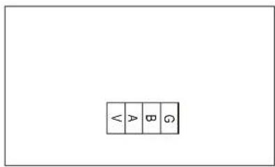
| Sign | Meaning |
| V | 12V (power +) |
| A | 485A |
| B | 485B |
| G | GND (power -) |
Controller interface diagram & definitions.


Connections explained:
| No. | Sign Meaning | |
| 01 | P10-1/2/3(U/V/W) Compressor | |
| 02 | CN66 Compressor signal | |
| 03 | CN97 DC motor | |
| 04 | CN11 4-way valve | |
| 05 | CN18 Water pump | |
| 06 | CN13 Reserved | |
| 07 | P1 P2 | Live wire Neutral wire |
| 08 | CN10 | Program download interface |
| 09 | RS485 | Color line controller communication/WiFi |
| 10 | RS485-2 | The port for centralized control |
| 11 | CN15 | Electronic expansion valve |
| 12 | P13(L) | Resistance |
| 13 | P14(L) | Resistance |
| 14 | HP | System high pressure |
| 15 | LP | System low pressure |
| 16 | FS | Water flow switch |
| 17 | MODE | Mode switch |
| 18 | REMOTE | Emergency switch |
| 19 | IT | Water input temperature |
| 20 | SUT | System suction temperature |
| 21 | CT | System fan coil temperature |
| 22 | OT Water output temperature | |
| 23 | ET | System exhaust temperature |
| 24 | AT | Ambient temperature |
| 25 | CN99 | Low pressure sensor |
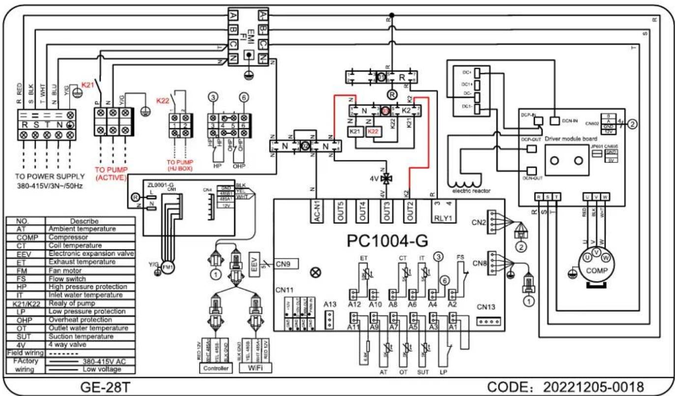
7.4 WIRING DIAGRAMS


7.5 WARRANTY TERMS
The only warranties given by the company are as set out in this warranty statement. The company gives no other conditions, guarantee, warranty or assurance and in particular, as the buyer is a business consumer who purchases for the purpose of resale, the provisions of the Consumer Guarantees Act 1993 or Australian consumer acts are excluded. The company warranties are offered subject to the goods having been installed and operated in accordance with procedures by the company and those recognized as standard industry practices. This in no way absolves the company from its liability as a manufacturer to the consumer under the Consumer Guarantees Act 1993 and or Australian consumer acts.
| 25 YEARS 3 YEARS | 2 YEARS 1 YEAR | ||
| Titanium heat exchanger | Compressor | Parts | Labour |
- Warranty terms are from date of purchase.
- This warranty excludes any defect or injury caused by or resulting from misuse, abuse, neglect, accidental damage, improper voltage, vermin infestation, incompetent installation, any fault not attributable to faulty manufacture or parts, any modifications which affect the reliability or performance of the unit.
- This warranty does not cover the following:
a. Natural Disasters (hail, lightening, flood, fire etc.)
b. Damage by foreign objects
c. Rust or damage to paintwork caused by a corrosive atmosphere
d. When serviced by an unauthorized person without the permission of Guardian
e. When a unit is installed by an unqualified person
f. Where a unit is incorrectly installed
g. When failure occurs due to improper or faulty installation
h. Failure due to improper maintenance (refer Operating Instructions)
i. Costs associated with delivery, handling, freighting, or damage to the product in transit.
- If warranty service is required, you should:
a. contact Guardian Support at: support@guardianpoolheating.com.au
b. provide as much detail on the issues you are encountering
c. provide a copy of your receipt as proof of purchase
d. have completed the online Warranty Registration Form
- Onsite technical service is available within a 25km radius of your Guardian Service Agents. Service outside this area will incur a traveling fee.
- Unless otherwise specified to the purchaser, the benefits conferred by this express warranty and additional to all other conditions, warranties, rights and remedies expressed or implied by the Trade Practices Act 1974 and similar consumer protection provisions contained in legislation of the States and Territories and all other obligations and liabilities on the part of the manufacturer or supplier and nothing contained herein shall restrict or modify such rights, remedies, obligations or liabilities.
LABOUR COSTS
Warranty for installation labour is twelve (12) months from date of purchase.
Any product found to be faulty due to installation/labour fault shall be covered under warranty and will be repaired or replaced by Guardian at their cost for a period of twelve (12) months from date of installation.
All replacement parts / components will be supplied direct by the company. Should the buyer purchase parts / components from their own supplier the company may at their own discretion reject or reimburse the cost to which the company can purchase the part for.
- GUARDIAN
- ECOPRO SERIES
- TROUBLESHOOTING GUIDE....12
- MAINTENANCE & INSPECTION....19
- APPENDIX....23
- BEFORE YOU BEGIN
- FOREWARD
- Thank you!
- WARNINGS
- SPECIFICATIONS
- PERFORMANCE DATA
- LOCATION OF INSTALLATION
- PLUMBING OF THE UNIT
- ELECTRICAL WIRING
- FIRST TIME STARTUP
- STARTUP PROCEDURE
- TIME DELAY
- USE & OPERATION
- THE CONTROL PANEL
- USING THE CONTROL PANEL
- ON/OFF MODE
- SWITCHING MODES
- SMART, BOOST & ECO MODES
- SETTING THE TEMPERATURE
- CLOCK SETTINGS
- TIMER SETTINGS
- SETTING ON/OFF TIMER
- SILENT SETTINGS
- SETTING A SILENT TIMER
- ONE-CLICK SILENT
- KEYBOARD LOCK
- FAULT INTERFACE
- TROUBLESHOOTING GUIDE
- WI-FI OPERATION
- INTRODUCTION
- Troubleshooting:
- INSTALLATION
- APP SETUP
- CREATE AN ACCOUNT
- ADD YOUR DEVICE & CONFIGURE WI-FI
- DEVICE MANAGEMENT
- MAINTENANCE & INSPECTION
- CHECKS TO THE AREA
- WORK PROCEDURE
- GENERAL WORK AREA
- CHECKING FOR PRESENCE OF REFRIGERANT
- PRESENCE OF FIRE EXTINGUISHER
- NO IGNITION SOURCES
- VENTILATED AREA
- CHECKS TO THE REFRIGERATION EQUIPMENT
- CHECKS TO ELECTRICAL DEVICES
- REPAIRS TO SEALED COMPONENTS
- ENSURE THAT APPARATUS IS MOUNTED SECURELY.
- REPAIR TO INTRINSICALLY SAFE COMPONENTS
- CABLING
- DETECTION OF FLAMMABLE REFRIGERANTS
- LEAK DETECTION METHODS
- REMOVAL AND EVACUATION
- LABELLING
- RECOVERY
- DECOMMISSIONING
- CHARGING PROCEDURES
- APPENDIX
- CABLE SPECIFICATIONS
- REFRIGERANT SATURATION TEMPERATURE
- INTERFACE DIAGRAMS
- WARRANTY TERMS
- LABOUR COSTS
Brand : Guardian
Model : Eco Pro GE-12
Category : Water heater