MT42 - Tondeuse à fil Maruyama - Free user manual and instructions
Find the device manual for free MT42 Maruyama in PDF.


| Product Type | Mini Tiller/Cultivator |
| Engine Displacement | 41.8 cc |
| Fuel Tank Capacity | 33.8 oz (1 liter) |
| Oil/Gas Ratio | 50:1 (2.6 oz per gallon) |
| Tilling Width | 6 - 10 inches |
| Tilling Depth | 4 inches maximum |
| Tine Speed | 250 rpm |
| Wheel Size | 1.375 x 7.0 inch diameter |
| Dimensions (L x W x H) | 23 x 20 x 20 inches |
| Transmission | Gear driven, ratio 32:1 |
| Carburetor | Walbro diaphragm type |
| Ignition | Solid state |
| Spark Plug | NGK BPM8Y (gap 0.024-0.028 in) |
| Anti-Vibration | Dual isolation grip and engine mount |
| Sound Power Level | 93 dBA |
| Depth Control | Adjustable drag stake |
| Wheel Adjustment | 3 positions for transport and tilling |
| Tines | Replaceable, set of 4 (A, B, C, D) |
| Fuel Type | Unleaded regular (89+ octane, max 10% ethanol) |
| Oil Type | BLUE Ultra-Shield 2-cycle synthetic blend |
| Safety Features | Throttle control, engine stop switch, spark arrester, safety decals |
Frequently Asked Questions - MT42 Maruyama
User questions about MT42 Maruyama
0 question about this device. Answer the ones you know or ask your own.
Ask a new question about this device
Download the instructions for your Tondeuse à fil in PDF format for free! Find your manual MT42 - Maruyama and take your electronic device back in hand. On this page are published all the documents necessary for the use of your device. MT42 by Maruyama.
USER MANUAL MT42 Maruyama
THANK YOU AND CONGRATULATIONS...
on your purchase of a new MT42 MINI TILLER/CULTIVATOR from Maruyama. We have worked to ensure that your Maruyama Auger will be one of the most trouble-free and satisfying pieces of equipment you have ever owned. With proper care, your powerhead will provide many years of service.
Please take the time to read this manual carefully to learn how to correctly operate and maintain your equipment. Maruyama reserves the right to change, alter or improve the product and this document at any time without prior notice.
CONTENTS
Introduction 2
Warnings and Safety Precautions....3-7
Specifications/Features 8
Assembly 9-10
Operation 11-13
Maintenance & Storage....14-17
Troubleshooting and Repair....17-18
Parts Breakdown....19-25
Border-Edger Kit Installation....26
Dethatcher Kit Installation 27
Warranty 28-29
Declarations of Conformity 30-31
FEDERAL EMISSIONS INFORMATION
MARUYAMA warrants to the retail purchaser, that this small, off-road engine was designed, built and equipped to conform at the time of initial sale to all applicable regulations of the U.S. Environmental Protection Agency (EPA).
REGISTRATION, SERVICE AND MAINTENANCE LOG
Record the model number and serial number In the space provided for easy reference. Warranty is valid only if the completed registration is received by MARUYAMA within 30 days of purchase. You can register your warranty online by visiting www.getearthquake.com. If you do not have a computer, call our customer service department at (800) 000-0000 Mondays through Fridays from 8 a.m. to 5 p.m. CST.
| OWNERSHIP RECORDS | ||
| Owner's Name: | ||
| Owner's Address: | ||
| City: | State/Province: | Zip Code/Postal Code: |
| Model Number: | Serial Number: | |
| Date of Purchase: | ||
| Notes: | ||
This instruction book contains information for several models. Read and keep this book for future reference. This book contains important information on SAFETY, ASSEMBLY, OPERATION, AND MAINTENANCE. The owner must be certain that all the product information is included with the unit. This information includes the INSTRUCTION BOOKS, the REPLACEMENT PARTS and the WARRANTIES. This information must be included to make sure state laws and other laws are followed.
WARNINGS AND SAFETY PRECAUTIONS
OWNER'S RESPONSIBILITY
Accurate assembly and safe and effective use of the machine is the owner's responsibility.
• Read and follow all safety instructions.
• Carefully follow all assembly instructions.
- Maintain the machine according to directions and schedule included in this Earthquake operator's manual.
- Ensure that anyone who uses the machine is familiar with all controls and safety precautions.
SPECIAL MESSAGES
Your manual contains special messages to bring attention to potential safety concerns, machine damage as well as helpful operating and servicing information. Please read all the information carefully to avoid injury and machine damage.
NOTE: General information is given throughout the manual that may help the operator in the operation or service of the machine.

This symbol points out important safety instructions which if not followed could endanger your personal safety. Read and follow all instructions in this manual before attempting to operate this equipment.
BEFORE OPERATING ENGINE:
Please read this section carefully. Read entire operating and maintenance instructions for this product. Failure to follow instructions could result in serious injury or death. Operate the machine according to the safety instructions outlined here and inserted throughout the text. Anyone who uses this machine must read the instructions and be familiar with the controls.

WARNING
WARNING INDICATES A HAZARD WHICH, IF NOT AVOIDED, COULD RESULT IN DEATH OR SERIOUS INJURY AND/OR PROPERTY DAMAGE.

CAUTION
CAUTION INDICATES YOU CAN BE HURT OR YOUR EQUIPMENT DAMAGED IF THE SAFETY INSTRUCTIONS THAT FOLLOW THIS SIGNAL WORD ARE NOT OBEYED.

IMPORTANT
INDICATES HELPFUL INFORMATION FOR PROPER ASSEMBLY, OPERATION, OR MAINTENANCE OF YOUR EQUIPMENT.

WARNING
CALIFORNIA PROPOSITION 65 WARNING
ENGINE EXHAUST FROM THIS PRODUCT CONTAINS CHEMICALS KNOWN TO THE STATE OF CALIFORNIA TO CAUSE CANCER, BIRTH DEFECTS, OR OTHER REPRODUCTIVE HARM.

WARNING
YOU MUST READ, UNDERSTAND AND COMPLY WITH ALL SAFETY AND OPERATING INSTRUCTIONS IN THIS MANUAL BEFORE ATTEMPTING TO SETUP AND OPERATE YOUR MACHINE.
FAILURE TO COMPLY WITH ALL SAFETY AND OPERATING INSTRUCTIONS CAN RESULT IN LOSS OF MACHINE CONTROL, SERIOUS PERSONAL INJURY TO YOU AND/OR BYSTANDERS, AND RISK OF EQUIPMENT AND PROPERTY DAMAGE. THE TRIANGLE IN THE TEXT SIGNIFIES IMPORTANT CAUTIONS OR WARNINGS WHICH MUST BE FOLLOWED.


Intended Use / Foreseeable Misuse
This is a motorized mini-cultivator that cultivates and loosens soil. It is pedestrian controlled. It has a petrol-fuelled internal combustion engine that powers the tines. It shall not be used for any other purpose.
GENERAL SAFETY RULES
- Read, understand, and follow all instructions on the machine and in the manual(s). Be thoroughly familiar with the controls and the proper use of the machine before starting.
• Use this equipment for its intended purpose only. - Familiarize yourself with all of the safety and operating decals on this equipment and on any of its attachments or accessories.
• Do not put hands or feet near or under rotating parts. - Only allow responsible individuals who are familiar with the instructions to operate the machine. Do not allow children to operate this machine. Do not allow adults to operate the machine without proper instruction.
- Thoroughly inspect the area where the machine is to be used and remove all foreign objects. Your equipment can propel small objects at high speed causing personal injury or property damage. Stay away from breakable objects, such as house windows, automobile, greenhouses, etc.
- Wear appropriate clothing such as a long-sleeved shirt or jacket. Also wear long trousers or slacks. Do not wear shorts. Never wear sandals, sneakers, or open shoes, and never operate the machine with bare feet.
- Do not wear loose clothing or jewelry. They can get caught in moving parts. Always keep hands, feet, hair and loose clothing away from any moving parts on engine and machine.
- Always wear safety goggles or safety glasses with side shields when operating the machine to protect your eyes from foreign objects which can be thrown from the unit. Always wear a protective hearing device.
• Always wear work gloves and sturdy footwear. Wear footwear that will improve footing on slippery surfaces. Leather work shoes or short boots work well for most people. These will protect the operator's ankles and shins from small sticks, splinters, and other debris. - It is advisable to wear protective headgear to prevent the possibility of being struck by small flying particles, or being struck by low hanging branches, twigs, or other objects which may be unnoticed by the operator.
- Do not operate the machine without proper guards or other safety protective devices in place.
- See manufacturer's instructions for proper operation and installation of accessories. Only use accessories approved by the manufacturer.
• Operate only in daylight or good artificial light. -
Do not operate product when fatigued or under the influence of alcohol, drugs or other medication which can cause drowsiness or affect your ability to operate this machine safely.
-
Never operate machine in wet grass. Always be sure of your footing; keep a firm hold on the handle and walk; never run.
- Watch for traffic when operating near, or when crossing roads.
- If the equipment should start to vibrate abnormally, stop the engine (motor), disconnect the spark plug wire and prevent it from touching the spark plug. Check immediately for cause. Vibration is generally a warning of trouble. If the noise or vibrations of the machine increase, stop immediately and perform an inspection.
- Never leave the machine unattended when the engine is running. Remove the wire from the spark plug.
• Regularly inspect the machine. Make sure parts are not bent, damaged or loose. - Temperature of muffler and nearby areas may exceed 150° F (65° C). Allow muffler and engine areas to cool before touching. Never pick up or carry the machine while the engine is running.
- Prolonged exposure to noise and vibration from gasoline engine-powered equipment should be avoided. Take intermittent breaks and/or wear ear protection from engine noise as well as heavy work gloves to reduce vibration in the hands.
- Keep all screws, nuts and bolts tight.
- Do not transport the machine from one place to another with the engine running.
- When moving the packaged machine, always do so with a partner.
- Check local regulations for age restrictions on use of this machine.
PRODUCT-SPECIFIC SAFETY RULES
- Do not cultivate above underground utilities, including water lines, gas lines, electric cables, or pipes. Do not operate the machine on terrain/soil with large rocks and foreign objects which can damage the equipment.
• After striking a foreign object, stop the engine. Remove the wire from the spark plug. Inspect the machine for damage. If damaged, repair before starting and operating the machine. - The tines of the cultivator should not rotate when the engine is idling. If it does rotate when engine is idling, contact Earthquake for instructions.
- If an object becomes lodged in the tines, turn engine off, remove the wire from the spark plug and secure, allow to cool before attempting to remove the foreign object.
- The clutch will transfer maximum power after about two hours of normal operation. During this break-in period clutch slippage may occur. The clutch should be kept free of oil or other moisture for efficient operation.
ENGINE SAFETY PRECAUTIONS
Warning Carbon Monoxide Poisoning
Engines give off carbon monoxide, an odorless, colorless, poisonous gas. Carbon monoxide may be present even if you do not smell or see any engine exhaust. Breathing carbon monoxide can cause nausea, fainting or death, in addition to drowsiness, dizziness and confusion. If you experience any of these symptoms, seek fresh air and medical attention immediately.
If your product comes with a separate engine manual, be sure to read and follow all safety and warning precautions outlined there, in addition to any in this manual.
Preventing Carbon Monoxide Poisoning
• Always start and run engine outdoors. Do not start or run engine in an enclosed area, even if doors or windows are open.
- Never try to ventilate engine exhaust indoors. Carbon monoxide can reach dangerous levels very quickly.
- Never run engine outdoors where exhaust fumes may be pulled into a building.
- Never run engine outdoors in a poorly ventilated area where the exhaust fumes may be trapped and not easily taken away. (Examples include: in a large hole or areas where hills surround your working area.)
- Never run engine in an enclosed or partially enclosed area. (Examples include: buildings that are enclosed on one or more sides, under tents, car ports or basements.)
• Always run the engine with the exhaust and muffler pointed in the direction away from the operator.
- Never point the exhaust muffler towards anyone. People should always be many feet away from the operation of the engine and its attachments.
- Do not change the engine governor settings or over-speed the engine.
Gasoline Fires and Handling Fuel Safely
Use extra care in handling gasoline and other fuels. They are flammable and vapors are explosive.
- When storing extra fuel be sure that it is in an appropriate container and away from any fire hazards.
- Prevent fire and explosion caused by static electric discharge. Use only nonmetal, portable fuel containers approved by the Underwriter's Laboratory (U.L.) or the American Society for Testing & Materials (ASTM).
• Always fill fuel tank outside in a well ventilated area. Never fill your fuel tank with fuel indoors. (Examples Include: basement, garage, barn, shed, house, porch, etc.) Never fill tank near appliances with pilot lights, heaters, or other ignition sources. If the fuel has to be drained, this should

WARNING
ENGINES GIVE OFF CARBON MONOXIDE, AN ODORLESS, COLORLESS, POISONOUS GAS. CARBON MONOXIDE MAY BE PRESENT EVEN IF YOU DO NOT SMELL OR SEE ANY ENGINE EXHAUST. BREATHING CARBON MONOXIDE CAN CAUSE NAUSEA, FAINTING OR DEATH, IN ADDITION TO DROWSINESS, DIZZINESS AND CONFUSION.
IF YOU EXPERIENCE ANY OF THESE SYMPTOMS, SEEK FRESH AIR AND MEDICAL ATTENTION IMMEDIATELY.

CAUTION
HOT GASES ARE A NORMAL BY-PRODUCT OF A FUNCTIONING CATALYTIC CONVERTER. FOLLOW ALL SAFETY INSTRUCTIONS TO PREVENT BURNS AND FIRES.
DO NOT ALTER/MODIFY ENGINE:
NEVER ALTER OR MODIFY THE ENGINE FROM THE FACTORY. SERIOUS INJURY OR DEATH MAY OCCUR IF ENGINE IS MODIFIED OR ALTERED.
WHEN WORKING ON OR REPLACING PARTS FOR THE ENGINE OR PRODUCT, YOU MUST ALWAYS DISCONNECT SPARK PLUG WIRE FROM THE SPARK PLUG AND KEEP IT AWAY FROM THE SPARK PLUG.
be done outdoors. The drained fuel should be stored in a container specifically designed for fuel storage or it should be disposed of carefully.
- Never remove the fuel cap or add fuel with the engine running. Stop engine and allow to cool before filling.
- Do not smoke.
• Never drain fuel from engine in an enclosed area.
• Always wipe up excess (spilled) fuel from engine before starting. Clean up spilled fuel immediately. If fuel is spilled, do not start the engine but move product and fuel container from area. Clean up spilled fuel and allow to evaporate and dry after wiping and before starting. - Allow fuel fumes/vapors to escape from the area before starting engine.
- Test the fuel cap for proper installation before starting and using engine.
• Always run the engine with fuel cap properly installed on the engine.
• Always unscrew gas cap vent screw while engine is running.
• Never smoke while refilling engine fuel tank. - Do not store engine with fuel in fuel tank indoors. Fuel and fuel vapors are highly explosive.
• During storage, screw down gas cap vent screw tightly.
• Never pour fuel from engine fuel tank.
• Never siphon fuel by mouth to drain fuel tank.
• Always have an adult fill the fuel tank and never allow children to fill the engine.
- Never allow an adult or anyone under the Influence of drugs or alcohol to fill engine.
- When storing gasoline or equipment with fuel in the tank, store away from furnaces, stoves, water heaters or other appliances that have a pilot light or other ignition source because they can ignite gasoline vapors.
BURNS AND FIRES
The muffler, muffler guard and other parts of the engine become extremely hot during the operation of the engine. These parts remain extremely hot after the engine has stopped.
Prevention of Burns and Fires
• Never remove the muffler guard from the engine.
- Never touch the muffler guard because it is extremely hot and will cause severe burns.
- Never touch parts of the engine that become hot after operation.
• Always keep materials and debris away from muffler guard and other hot parts of the engine to avoid fires.
- This engine is designed to operate using a catalytic converter which contributes to the engine's compliance with the EPA.
CHILDREN AND BYSTANDERS
Tragic accidents can occur if the operator is not alert to the presence of children and/or bystanders. Never assume that others will remain where you last saw them.
- Keep the area of operation clean of all persons, especially small children and pets. Keep children under the watchful care of a responsible adult.
• Be alert and turn machine off if children enter the area.
• Before and while moving backwards, look behind and down for small children.
• Never allow children to operate the machine.
• Use extra care when approaching blind corners, shrubs, trees, or other objects that may obscure vision.
SERVICE
- Always stop the engine whenever you leave the equipment, before cleaning, repairing or inspecting the unit. Engine should be turned off and cool, spark plug wire must be removed from spark plug before any repairs or adjustments are attempted. Never make adjustments or repairs with the engine (motor) running. Disconnect the spark plug wire, and keep the wire away from the plug to prevent accidental starting. Remove the ignition key if equipped with an electric start.
• Always wear eye protection when you make adjustments or repairs. - Keep all nuts and bolts tight and keep equipment in good condition.
- Never tamper with safety devices. Check their proper operation regularly.
- When servicing or repairing the machine, do not tip the machine over or up unless specifically instructed to do so in this manual. Service and repair procedures can be done with the machine in an upright position. Some procedures will be easier if the machine is lifted on a raised platform or working surface.
• To reduce fire hazard, keep machine free of grass, leaves, or other debris build-up. Clean up oil or fuel spillage. Allow machine to cool before storing. - Stop and inspect the equipment if you strike an object. Repair, if necessary, before restarting.
• Clean and replace safety and instruction decals as necessary.
• To guard against engine over-heating, always have engine debris filter mounted and clean. - Inspect machine before storage. When not in use, disconnect spark plug lead and store indoors in a dry place locked or otherwise inaccessible to children.
• Use only original equipment parts from Maruyama, including all nuts and bolts.
SAFETY DECALS
This mini-cultivator has been designed and manufactured to provide you with the safety and reliability you would expect from an industry leader in outdoor power equipment manufacturing.
Reading this manual and the safety instructions it contains will provide you with the necessary basic knowledge to operate this equipment safely and effectively. We have placed a safety decal on the cultivator to remind you of some of this important information while you are operating the unit.
These Important safety decals are illustrated below, and are shown here to help familiarize you with the location and content of the safety messages you will see as you perform normal cultivating operations. Please review these decals now, and if you have any questions regarding its meaning or how to comply with these instructions, reread the complete safety instruction text in this manual, or contact your local dealer.
Should a decal become unreadable because of being worn, faded, or otherwise damaged during the use of your mini-cultivator, please use the part number information provided to order a replacement label from your local authorized dealer. These decals are easily applied, and will act as a constant visual reminder to you, and others who may use the equipment, to follow the safety instructions necessary for safe, effective operation of your mini-cultivator.
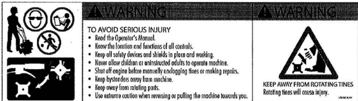

WARNING AND OTHER DECALS

natural_image
Silhouette of a person wearing headphones and glasses, enclosed in a black circular frame (no text or symbols)Wear ear and eye protection while using product

Keep away from
moving parts

Hot surfaces. Do not touch.

Declared noise level
SPECIFICATIONS
| ENGINE DISPLACEMENT | 41.8cc |
| FUEL TANK CAPACITY | 33.8 oz. / 1 liter |
| OIL/GAS RATIO | 50:1 - 2.6 ounces per gallon |
| OIL TYPE | BLUE Ultra-Shield (# 841250) |
| GASTYPE | Unleaded Regular Gas |
| SPARK PLUG | NGK BPM8Y |
| SPARK PLUG GAP | 0.024-0.028 (0.6-0.7 mm) |
| TRANSMISSION | Gear Driven |
| GEAR RATIO | 32:1 |
| TILLING WIDTH | 6" minimum - 10" maximum |
| TILLING DEPTH | 4" maximum |
| TINE SPEED | 250 rpm |
| WHEEL SIZE | 1.375 x 7.0 inch diameter |
| WEIGHT OF UNIT | |
| UNIT SIZE L x W x H (inches) | 23" x 20" x 20" |
| EPA Approved | Yes |
| Anti-Vibration | Dual Isolation-grip & engine mount |
| Carburetor | Walbro Diaphragm Type |
| Ignition | Solid State |
FEATURES
CE SOUND AND VIBRATION LEVELS
| Model | 2006/42/ECOperator Ear L_PA (dBA) | 2006/42/ECSound Power Level L_WA (dBA) |
| MT42 | 71 | 93 |
| Model | 2006/42/ECHand/Arm VibrationMax m/s ^2 | 2006/42/ECVibration Time Limit |
| MT42 | 4.83 | EAV: 2h 9mELV: 8h 34m |
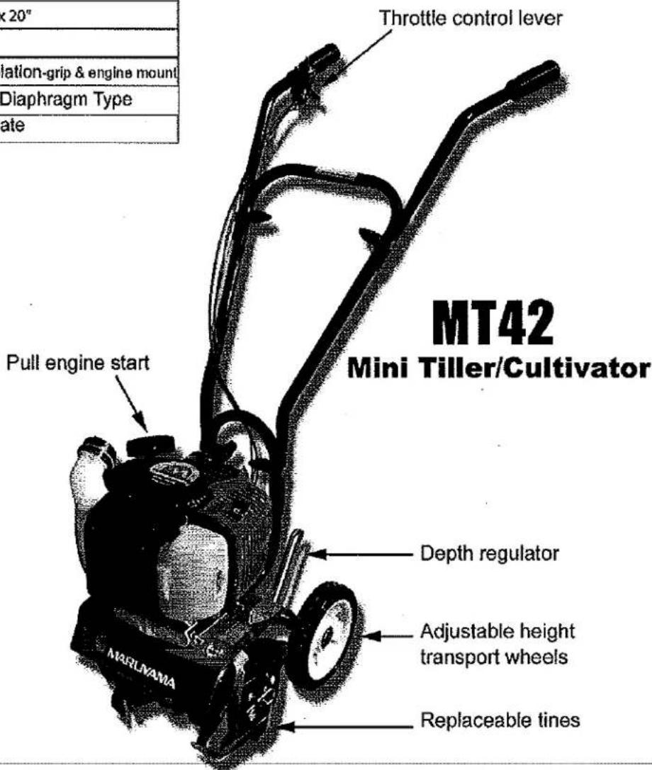
ASSEMBLY
UNPACK MINI-CULTIVATOR
- Carefully lift the mini-cultivator out of the box, remove any packing material and cut any ties holding the handlebar pieces to the mini-cultivator assembly.
ASSEMBLY
- Stand the mini-cultivator assembly upright with tines and wheels on a level surface. Wheels should be set in the lowest position. DO NOT place the mini-cultivator on a high surface where it can fall and cause property-damage or personal injury.
- Using two tee handle nuts (4640), two bolts (4642), and two curved washers (4641), assemble the middle handlebar (4693) to the lower handlebar (4695) that is already attached to the mini-cultivator assembly. SEE FIGURE 1. The middle handlebar can be installed in two positions one high and one low. DO NOT overtighten the tee handle nuts.
- Attach the upper right and left handlebars (4689 & 4690) to the middle handlebar using the two remaining tee handle nuts, bolts, and curved washers. SEE FIGURE 1. DO NOT overtighten the tee handle nuts.
- The drag stake is shipped with point facing upwards. Before using, remove detent pin and turn the drag stake around so the point is directed in the downward position facing towards the tines. Re-insert detent pin. SEE FIGURE 2.
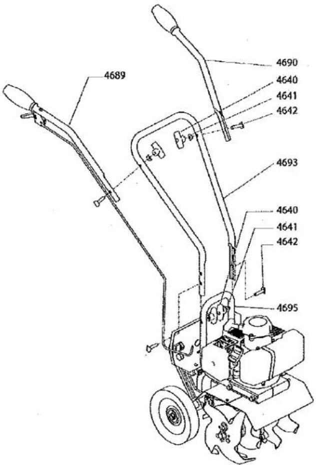
Figure 1
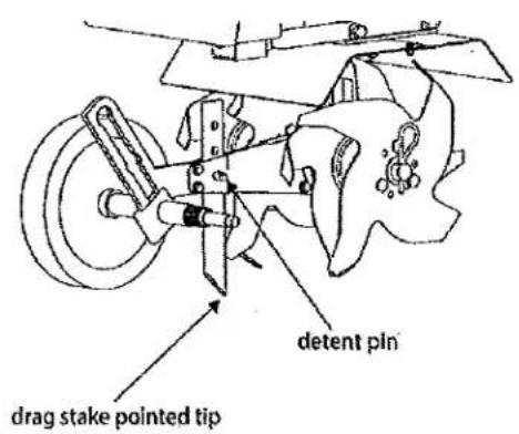
Figure 2
OPERATION
PREPARING ENGINE FOR STARTING
GAS AND OIL
Quality
To operate the engine, we recommend using Maruyama's BLUE Ultra-Shield™ 2-cycle Synthetic Blend Oil to extend the life of the engine and to ensure that the engine performs at its maximum potential.
Use only unleaded regular gasoline (89+ octane or higher). Use gasoline with no more than 10% alcohol/ethanol.
Mixture
Run engine with a 50:1 ratio.

Fuel Mixture Chart
| Gasoline | 50:1 2-cycle oil |
| 1 gallon | 2.6 oz. |
| 2 gallons | 5.1 oz. |
| 5 gallons | 12.8 oz. |
| 1 liter | 20 ml |
| 5 liter | 100 ml |
MIXING FUEL AND FILLING FUEL TANK
Mixing Fuel
- Fuel must be mixed in a container outside in a well ventilated area.
- Fill certified fuel container 1/4 full of recommended fuel.
- Add recommended amount of 2 cycle oil.
- Screw container cap on straight and tight.
- Shake the container to mix fuel and oil.
- Unscrew gas cap slowly to vent, add the remainder of fuel requirements.
- Wipe away any spilled fuel or oil and allow to evaporate before moving or transporting.

CAUTION
NEVER STORE ENGINE WITH FUEL IN THE TANK INDOORS. FUEL AND FUEL VAPORS ARE HIGHLY FLAMMABLE.
NEVER MIX FUEL AND OIL DIRECTLY IN ENGINE FUEL TANK. USE ONLY NONMETAL, PORTABLE FUEL CONTAINERS APPROVED BY THE UNDERWRITER'S LABORATORY (U.L.) OR THE AMERICAN SOCIETY FOR TESTING & MATERIALS (ASTM).
AN ADULT MUST ALWAYS HANDLE AND FILL THE ENGINE WITH FUEL.
ALWAYS HANDLE GAS IN A WELL VENTILATED AREA, OUTDOORS, AWAY FROM FLAMES OR SPARKS.
DO NOT START ENGINE IF FUEL IS SPILLED. WIPE OFF EXCESS FUEL AND ALLOW TO DRY. REMOVE ENGINE FROM AREA TO AVOID SPARKS.

IMPORTANT
THIS ENGINE USES A GAS/OIL MIXTURE. DO NOT RUN ON STRAIGHT GAS ONLY, ENGINE DAMAGE WILL RESULT.
Note:
Never use a mixing ratio less than 50:1 regardless of the oil package mixing instructions. Ratios less than 50:1, (for example, 60:1, 80:1, 100:1), reduce the amount of lubrication to the internal moving parts of the engine and can cause damage.
Filling Fuel Tank
- Shut-off engine and allow engine to completely cool before refilling the fuel tank.
- Move to a well ventilated area, outdoors, away from flames and sparks.
- Clean debris from area around the fuel cap.
- Loosen fuel cap slowly. Place the cap on a clean, dry surface.
- Carefully add fuel without spilling.
- Do not fill gas tank completely full, allow space for fuel to expand.
- Immediately replace fuel cap and tighten. Wipe off spilled fuel and allow to dry before starting engine.
OPERATION TIPS
- The clutch will transfer maximum power after about two hours of normal operation. During this break-in period clutch slippage may occur. The clutch should be kept free of oil and other moisture for efficient operation.
- Cultivate without placing excessive body weight on the unit. The mini-cultivator operates most efficiently with the weight of the unit itself.
- Never run engine indoors. Exhaust fumes are deadly.
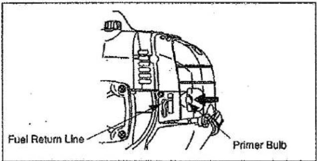
Cold Starting Procedure
The carburetor on this engine is equipped with a fuel primer and a choke system. To start a "cold" engine properly, perform the following procedure:
- Pump the primer bulb until fuel can be seen flowing through the fuel return line to the fuel tank. (Flowing fuel should be almost clear, not foamy or full of bubbles.)
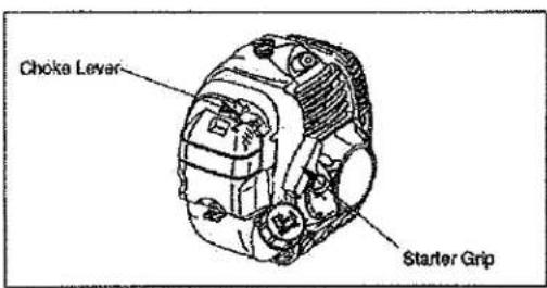
- Turn the choke lever to the Close position.
- With the stop switch "ON", and the throttle trigger positioned at Fast-idle position, pull the starter grip.

WARNING
MAKE SURE THE UNIT IS IN A STABLE POSITION BEFORE PULLING THE STARTER HANDLE.
WHEN THE UNIT STARTS TO FIRE OR RUN, RELEASE THE THROTTLE CONTROL MOMENTARILY WITH YOUR RIGHT HAND AND RETURN YOUR LEFT HAND TO THE HANDLEBAR POSITION TO MAINTAIN CONTROL AND STABILITY OF THE UNIT WITH BOTH HANDS.

CAUTION
IF ENGINE FAILS TO START AFTER TRYING STARTING PROCEDURES, PLEASE CONTACT OUR CUSTOMER SERVICE DEPARTMENT AT 800-345-6007.
STARTER ROPE CAN CAUSE AN UNANTICIPATED JERK TOWARDS ENGINE. PLEASE FOLLOW INSTRUCTIONS TO AVOID INJURY.
NEVER LEAVE ENGINE RUNNING WHILE UNATTENDED. TURN OFF AFTER EVERY USE.
NEVER CARRY MINI-CULTIVATOR FROM ONE LOCATION TO ANOTHER WHILE ENGINE IS RUNNING.
ALWAYS WEAR A PROTECTIVE HEARING DEVICE.
DO NOT START ENGINE IF FUEL IS SPILLED. WIPE OFF EXCESS FUEL AND ALLOW TO DRY.

CAUTION
- Do not pull the Starter rope all the way out.
NOTE: If engine fails to start after 5-6 pulls, push primer 1 time and pull starter rope again.
- After engine starts running, move choke lever to HALF CHOKE position until the unit runs smoothly.
NOTE: Half choke is defined when the choke lever is between STOP/OFF and START/ON.
- Move choke lever to the ON position and move throttle to desired speed.
*Do not let unit run idle for extended periods of time.
- To stop engine, push rocker switch to STOP.
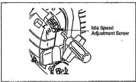
Idle Speed Adjustment
The CER420 engine is equipped with a non-adjustable fuel mixture carburetor. The engine idle speed is the only adjustment for the operator.
To adjust the engine idle speed, rotate the idle speed adjustment screw on the carburetor (see below).
* Turn the idle speed screw clockwise to Increase the engine idle speed.
* Turn the speed adjust. screw Counterclockwise to decrease the engine idle speed.
ADJUSTING WHEELS AND DRAG STAKE
The wheels on the mini-cultivator can be adjusted to one of three positions. The lowest wheel position is used for transporting the mini-cultivator across a smooth level surface while the engine is not running. The two higher positions are used when cultivating in soil and help stabilize the unit when cultivating at different depths. SEE FIGURE 4.
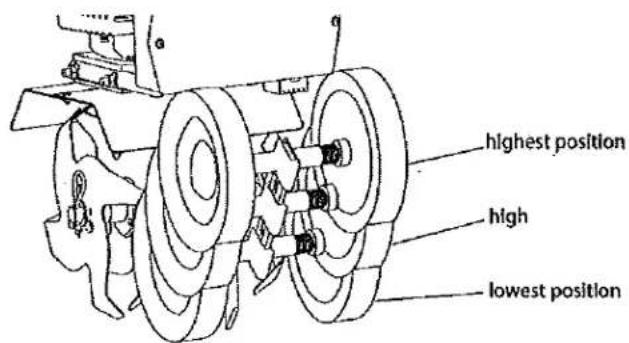
Figure 4
To adjust wheels up or down, SEE FIGURES 5 AND 6.
- Pull the locking metal sleeve against the spring until it releases from one of the three holes in the vertical guide.
- Slide the wheel set up or down to the desired position, and release the locking metal sleeve until it locks into one of the three holes in the vertical guide.
The drag stake is used to help regulate cultivating depth and control the mini-cultivator from leaping forward during operation. Resistance to forward motion is greatest when the drag stake is set in its lowest position allowing for deeper cultivation.
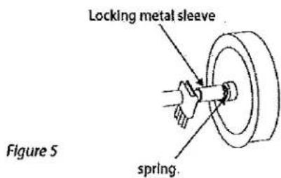
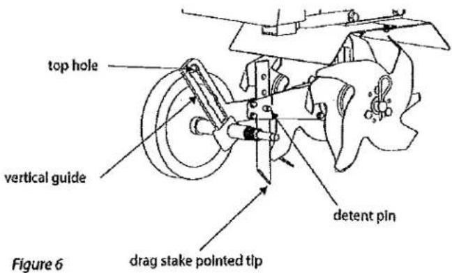
To adjust the drag stake (SEE FIGURE 6):
- Pull the pin out of the drag stake mount hole.
- Position the drag stake so the pointed tip is directed downward.
- Insert the pin into the hole that achieves desired depth.
MAINTENANCE AND STORAGE
STEPS FOR WORKING ON EQUIPMENT
- Turn off engine switch.
- Disconnect the spark plug wire from the spark plug.
- Securely place the disconnected spark plug wire away from the spark plug and any metal parts. This must always be done or arcing may occur between spark plug wire and metal parts.
- Replace or repair the part on the mini-cultivator.
- Check all parts that were repaired, or removed during repair, that they are secure and fit correctly.
NOTE: All repair parts must come from the factory. Never replace parts that are not specifically designed for the mini-cultivator. - Reconnect the spark plug wire.
MINI-CULTIVATOR MAINTENANCE
- The transmission case has grease installed at the factory. It is recommended that once a year the gear case be split by a qualified service professional and the grease level checked. Add a molyllithium type grease only if level of grease is below top of the gears. DO NOT OVERFILL.
- Keep all screws, nuts, and bolts tight.
- For cold weather operation, store the unit in a cool environment. Transferring the unit from a cold to a warm place can cause the build up of harmful condensation.
ENGINE MAINTENANCE
Please read the maintenance schedule and observe these recommendations to extend the life of your engine.
Good maintenance is essential for safe, economical, and trouble-free operation. It will also help reduce air pollution. To help you properly care for your engine, the following pages include a maintenance schedule, routine inspection procedures, and simple maintenance procedures using basic hand tools. Other service tasks that are more difficult, or require special tools, are best handled by professionals and are normally performed by a technician or other qualified mechanic.
Maintenance, replacement or repair of the emissions control devices and systems may be performed by any non-road engine repair establishment or individuals. However, items must be serviced by an authorized dealer to obtain "no charge" emissions control service.
The maintenance schedule applies to normal operating conditions. If you operate your engine under unusual conditions, such as sustained high-load or high-temperature operation, or use in unusually wet or dusty conditions, consult your servicing dealer for recommendations applicable to your individual needs and use.

CAUTION
PRACTICE SAFETY AT ALL TIMES. ENGINE MUST BE TURNED OFF AND ALLOWED TO COOL, AND SPARK PLUG WIRE MUST BE DISCONNECTED BEFORE ATTEMPTING ANY MAINTENANCE OR REPAIR.
TO PREVENT ACCIDENTAL STARTING:
ENGINE MUST BE TURNED OFF AND COOL, AND SPARK PLUG WIRE MUST BE REMOVED FROM SPARK PLUG BEFORE CHECKING AND ADJUSTING ENGINE OR EQUIPMENT.
TEMPERATURE OF MUFFLER AND NEARBY AREAS MAY EXCEED 150° F (65° C). AVOID THESE AREAS.
CHECK MINI-CULTIVATOR OFTEN FOR LOOSE NUTS AND BOLTS. KEEP THESE ITEMS TIGHTENED.
NEVER STORE ENGINE WITH FUEL IN THE TANK INSIDE A BUILDING. POTENTIAL SPARKS MAY BE PRESENT FOR IGNITION OF FUEL AND FUEL VAPORS.
AN ADULT MUST ALWAYS DO MAINTENANCE AND REPAIR ON ENGINE AND MINI-CULTIVATOR.
ENGINE MUST BE SHUT-OFF, COOL, AND SPARK PLUG WIRE REMOVED BEFORE ANY REPAIR OR MAINTENANCE CAN BE DONE.
MAINTENANCE SCHEDULE
| MAINTENANCE ITEM | Every 8 hours (daily) | Every 20 hours or seasonally | Each Year | |
| Clean Engine and Check Bolts & Nut | X | |||
| Air Filter(See Air Filter section) | Check | X | ||
| Clean * | X | |||
| Replace | X | X | ||
| Spark Plug(Gap .028")(See Spark Plug section) | Check/Adjust | X | ||
| Replace | X | |||
* Service more frequently under dusty conditions
MAINTENANCE:
Air Filter Cleaning
Maintenance Interval
- The air filter should be cleaned daily, or more often when working in extremely dusty conditions.
-
Replace after every 100 hours of operation.
-
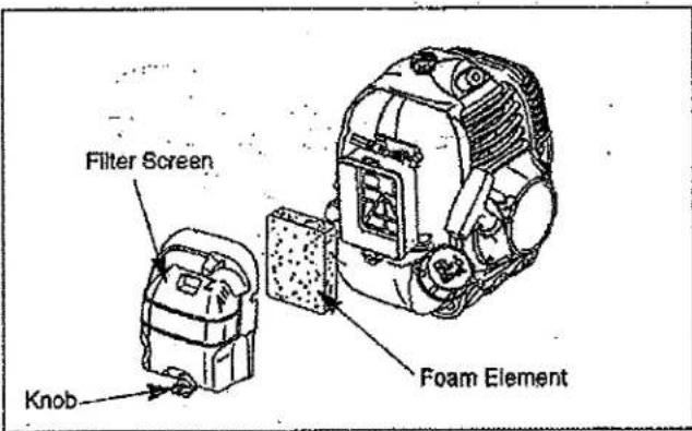
Loosen the knob and remove the air filter cover.
- Remove the foam element.
- Clean the foam element with warm, soapy water. Let the element dry completely.
- Apply a light coat of SAE 30 motor oil to the foam element and squeeze out all excess oil.
- Reassemble the foam element and filter cover.

IMPORTANT
NEVERTWIST AIR FILTERS WHEN CLEANING. ALWAYS PRESS.
Cylinder Cooling Fins
Maintenance Interval
- The cylinder cooling fins should be cleaned after every 25 hours of operation, or once a week, whichever comes first.
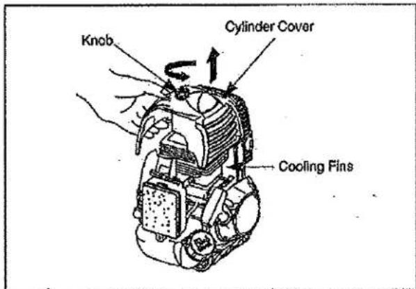
- Air must flow freely around and through the cylinder cooling fins to prevent engine overheating. Leaves, grass, dirt and debris buildup on the fins will increase the operating temperature of the engine, which can reduce engine performance and shorten engine life.
Cooling Fin Cleaning
- With the engine at ambient (room) temperature, loosen the knob and remove the air filter cover.
- Loosen the knob and lift off the cylinder cover.
- Clean all dirt and debris from the cooling fins and from around the cylinder base.
- DO NOT overlook cleaning of the cooling air intake area below the crankcase and above the fuel tank! This area must be free of debris and obstruction for the engine to cool properly.
- Reinstall the cylinder cover.
Fuel Filter
Maintenance Interval
The fuel filter should be replaced after every 100 hours of operation.
Fuel filters needing more frequent replacement may indicate debris in fuel tank.
Fuel Filter Replacement
The fuel filter is attached to the end of the fuel pick-up hose inside the fuel tank.
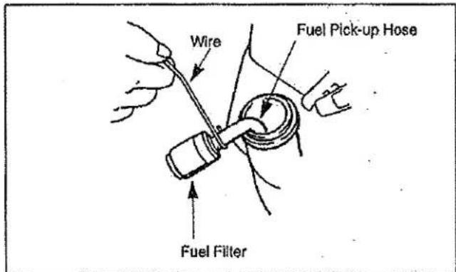
To replace the fuel filter:
- Make sure the fuel tank is empty.
- Remove the fuel cap.
- Using a wire hook, gently pull the fuel filter out through the fuel filler opening.
Use caution not to "fishook" the fuel tube. Replace immediately if punctured! - Grasp the fuel hose next to the fuel filter fitting and remove the filter, but do not release the hose.
- While still holding on to the fuel hose, attach the new fuel filter.
- Drop the new fuel filter back into the fuel tank.
- Make sure that the fuel filter is not stuck in a corner of the tank, and that the fuel hose is not doubled over (kinked) before refueling.
Spark Plug
Maintenance Interval
- The spark plug should be removed from the engine and checked after each 25 hours of operation.
- Replace the spark plug after every 100 hours of operation.
Spark Plug Maintenance
- Twist the high tension lead boot on the spark plug back and forth a couple of times to loosen the boot, then pull the boot off of the spark plug.
- Remove the spark plug.
- Clean the electrodes with a stiff brush.
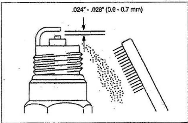
- Adjust the electrode air gap to .024-.028 in (0.6-0.7 mm).
- Replace the spark plug if it is oil-fouled, damaged, or if the electrodes are worn down.
- Do not overtighten the spark plug when installing. The tightening torque is 95-148 in. lbs. (10.7-16.6 N·m).
- Always use only the specific heat range of spark plug. This is particularly critical with today's low-emission engines. For best results, use the exact replacement.
Spark Arrester
Maintenance Interval
- The spark arrester should be inspected and cleaned after every 25 hours of use.
- Replace the screen if it cannot be thoroughly cleaned, or if it is damaged.
Spark Arrester Maintenance
- With the engine at ambient (room) temperature, loosen the knob and remove the air cleaner cover.
- Loosen the knob and lift off the cylinder cover.
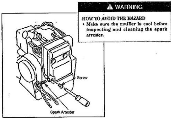
- Remove a screw located on the side of the exhaust outlet holds the spark arrester in place.
- Withdraw the spark arrester, using a suitable pair of pliers.
Note: Do not crush or distort the spark arrester flange during removal.
- The screen can be cleaned using a non-flammable solvent and stiff wire brush.
Note: If any part cannot be thoroughly cleaned, it must be replaced.
-
To install insert the spark arrester into the exhaust outlet while aligning the holes in the arrester flange and outlet for the retaining screw. Then install the screw.
-
Reinstall the cylinder and air filter covers.
Exhaust Muffler
Maintenance Interval
The muffler should be inspected and cleaned after each 100 hours of use.
Muffler Maintenance
- With the engine at ambient (room) temperature, loosen the knob and remove the air filter cover.
- Loosen the knob and lift off the cylinder cover.
- Withdraw the spark arrester using a suitable pair of pliers.
Note: Do not crush or distort the spark arrester flange during removal.
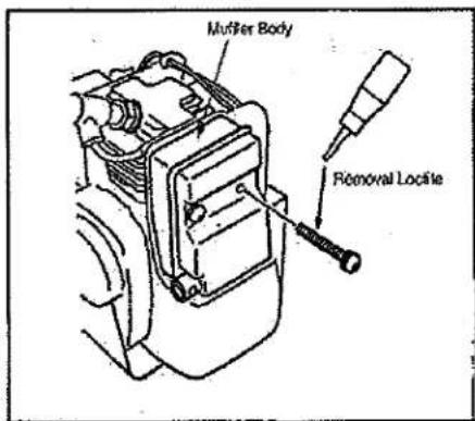
- Remove the three socket head screws holding the muffler body from cylinder.
- Clean exhaust port of cylinder, exhaust outlet of muffler and spark arrester with safety solvent and stiff brush.
IMPORTANT: Be careful not to allow any dirt or debris to fall into the exhaust ports, as this can cause engine damage.
- To reassemble the muffler body to the cylinder, apply Removal Loctite to the three socket head screws, then reinstall and tighten the three screws.
- Reinstall the spark arrester onto the muffler body, then reinstall and tighten the screw.
- Reinstall the cylinder and air filter covers.
TINE REMOVAL AND INSTALLATION
To Remove Tines
-
Remove the cotter pins from each end of the tine shaft.
-
Slide the four tines off the shaft.
To Install Tines
-
First slide the inside tines onto each end of the tine shaft. One inside tine is stamped with a "B" and the other is stamped with a "C".
-
Slide the outside tine "A" and tine "D" onto each end of the shaft next. The tines should be installed in the correct order so that they are positioned left to right A, B, C, D, as viewed from the user's position on the mini-cultivator. Make sure that the hub collars on both the right and left pairs of tines face each other so that there is adequate spacing between the tine blades. SEE FIGURE 12.
-
Insert the cotter pins into the holes at each end of the tine shaft to lock the tines into place.
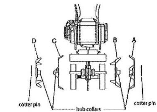
Figure 12 (Front View)

CAUTION
TO AVOID INJURY OR DEATH, NEVER SIPHON FUEL BY MOUTH.
NEVER STORE MINI-CULTIVATOR WITH FUEL IN THE FUEL TANK INSIDE AN ENCLOSED AREA OR BUILDING.
TRANSPORTING YOUR MINI-CULTIVATOR
- After using the mini-cultivator and before transporting it in a truck bed, screw the gas cap screw and gas cap on (clockwise) tightly. The gas cap will not leak during transporting if gas cap is tight and the screw at the top is tight. Never transport engine inside an enclosed space within a vehicle. Fuel or fuel vapors may ignite causing serious injury or death.
- If fuel is present in the fuel tank, transport in an open vehicle in an upright position.
- If an enclosed vehicle must be used, remove gas into an approved red fuel container. DO NOT siphon by mouth.
- Run engine to use up the fuel in the carburetor and fuel tank. Always run engine in a well ventilated area.
- Wipe away any spilled fuel from engine and mini-cultivator. Allow to dry.
- Gas cap and gas cap vent screw should be turned down tightly before transporting mini-cultivator in a vehicle.
LONG-TERM STORAGE
If your mini-cultivator will not be used for more than one month, prepare it for long term storage.
Steps for Long Term Storage
- Remove the remainder of the fuel from the gas tank into an approved fuel container.
- Store mini-cultivator engine in a vertical position.
- Remove all debris from cultivator tines and engine.
TROUBLESHOOTING GUIDE
| PROBLEM | POSSIBLE CAUSE | REMEDY/ACTION |
| Engine will not start | 1. Power switch off | 1. Flip switch to ON position |
| 2. Spark plug wire disconnected | 2. Connect spark plug wire to spark plug | |
| 3. Out of fuel | 3. Refuel | |
| 4. Spark plug wet, faulty or improperly gapped | 4. Clean, replace or gap spark plug | |
| 5. Throttle control not held open | 5. Hold throttle control open when pulling recoil handle | |
| 6. Fuel line hose not positioned in bot- tom of gas tank | 6. Push fuel line down Into fuel In gas tank | |
| Engine runs rough, floods during operation | 1. Dirty air filter | 1. Clean or replace air filter |
| 2. Choke partially engaged | 2. Turn off choke | |
| 3. Carburetor out of adjustment | 3. Call factory | |
| Engine is hard to start | 1. Stale fuel | 1. Drain old fuel and replace with fresh. Use gas stabilizer at end of season |
| 2. Spark plug wire loose | 2. Make sure spark wire is securely attached to spark plug | |
| 3. Dirty carburetor | 3. Clean carburetor, use gas stabilizer, new gas can | |
| 4. Throttle control not held open | 4. Prime unit 3 more times, then hold throttle open when pulling recoil handle | |
| Engine misses or lacks power | 1. Clogged gas tank | 1. Remove and clean gas tank |
| 2. Clogged air filter | 2. Clean or replace air filter | |
| 3. Carburetor out of adjustment or bad | 3. Call factory | |
| 4. Spark plug wet, faulty or improperly gapped | 4. Clean, replace or gap spark plug | |
| Engine runs, then quits | 1. Gas cap not venting | 1. Clean or replace gas cap, check vent |
| 2. Plugged fuel filter | 2. Clean or replace fuel filter | |
| 3. Carburetor out of adjustment or bad | 3. Call factory | |
| Engine revs too high | 1. Carburetor out of adjustment | 1. Call factory |
| Tines turn at Idle | 1. Idle speed too high | 1. Adjust Idle speed lower |
| 2. Broken clutch spring | 2. Replace spring |
PARTS BREAKDOWN
HANDLEBAR PARTS EXPLOSION
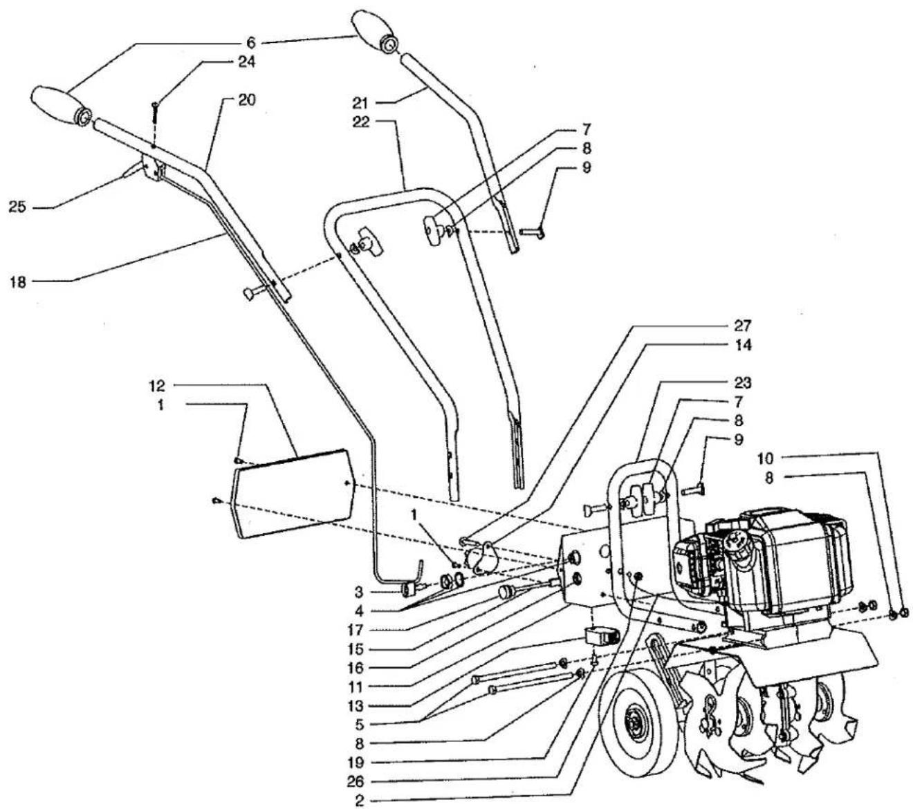
MT42 HANDLEBAR PARTS LIST
| KEY | PART # | DESCRIPTION | QTY. |
| 1 | 300471 | BOLT, M5 X 12MM | 3 |
| 2 | 300523 | GROUND WIRE | 1 |
| 3 | 46139 | KEY ONLY | 1 |
| 4 | 46140 | KEY SWITCH | 1 |
| 5 | 46141 | BOLT, HEX HD M8 X 1.25 X 160MM | 2 |
| 6 | 4639 | GRIP, HANDLEBAR | 2 |
| 7 | 4640 | NUT, T-HANDLE | 4 |
| 8 | 4641 | WASHER | 8 |
| 9 | 4642 | BOLT, HANDLE CLAMP | 4 |
| 10 | 4655 | NUT, HEX HD M8 X 1.25 | 2 |
| 11 | 4656 | BATTERY BOX MC43E | 1 |
| 12 | 4657 | COVER, BATTERY BOX | 1 |
| 13 | 4659 | VOLTAGE RECTIFIER | 1 |
| 14 | 4660 | SOLENOID | 1 |
| 15 | 4661 | CHARGER PIGTAIL | 1 |
| 16 | 4662 | NUT, CHARGER PIGTAIL | 1 |
| 17 | 4663 | CAP, CHARGER PIGTAIL | 1 |
| KEY | PART # | DESCRIPTION | QTY. |
| 18 | 4667 | THROTTLE CABLE | 1 |
| 19 | 4669 | BOLT, M6 X 1MM X 12MM PAN HD | 1 |
| 20 | 4689 | HANDLEBAR, UPPER RIGHT | 1 |
| 21 | 4690 | HANDLEBAR, UPPER LEFT | 1 |
| 22 | 4693 | HANDLEBAR, MIDDLE | 1 |
| 23 | 4695 | HANDLEBAR, LOWER | 1 |
| 24 | 4814 | BOLT, PHILLIPS TRUSS HD ZN 10-24 X 1-1/4 | 1 |
| 25 | 4819 | TRIGGER ASSEMBLY, LONG THROW W/O CABLE | 1 |
| 26 | 53106 | NUT, LOCK BI-WAY 1/4-20 | 2 |
| 27 | 6041612 | BOLT, PTH ZN 1/4-20 X 1-1/2 | 2 |
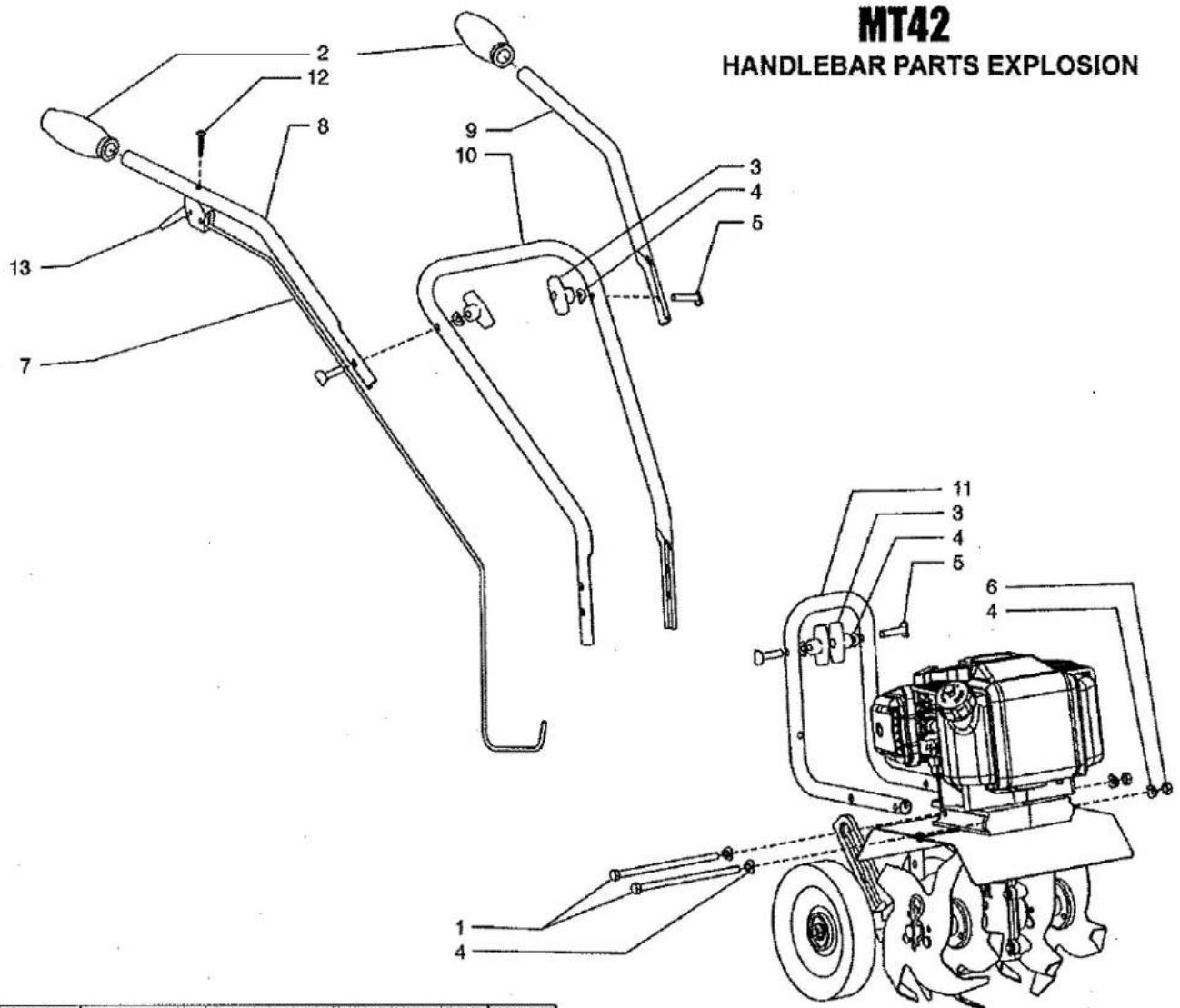
| KEY | PART # | DESCRIPTION | QTY. |
| 1 | 46141 | BOLT, HEX HD M8 X 1.25 X 160MM | 2 |
| 2 | 4639 | GRIP, HANDLEBAR | 2 |
| 3 | 4640 | NUT, T-HANDLE | 4 |
| 4 | 4641 | WASHER | 8 |
| 5 | 4642 | BOLT, HANDLE CLAMP | 4 |
| 6 | 4655 | NUT, HEX HD M8 X 1.25 | 2 |
| 7 | 4667 | THROTTLE CABLE | 1 |
| 8 | 4689 | HANDLEBAR, UPPER RIGHT | 1 |
| 9 | 4690 | HANDLEBAR, UPPER LEFT | 1 |
| 10 | 4693 | HANDLEBAR, MIDDLE | 1 |
| 11 | 4695 | HANDLEBAR, LOWER | 1 |
| 12 | 4814 | BOLT, PHILLIPS TRUSS HD ZN 10-24 X 1-1/4 | 1 |
| 13 | 4819 | TRIGGER ASSEMBLY, LONG THROW W/O CABLE | 1 |
HOOD & TINES PARTS EXPLOSION
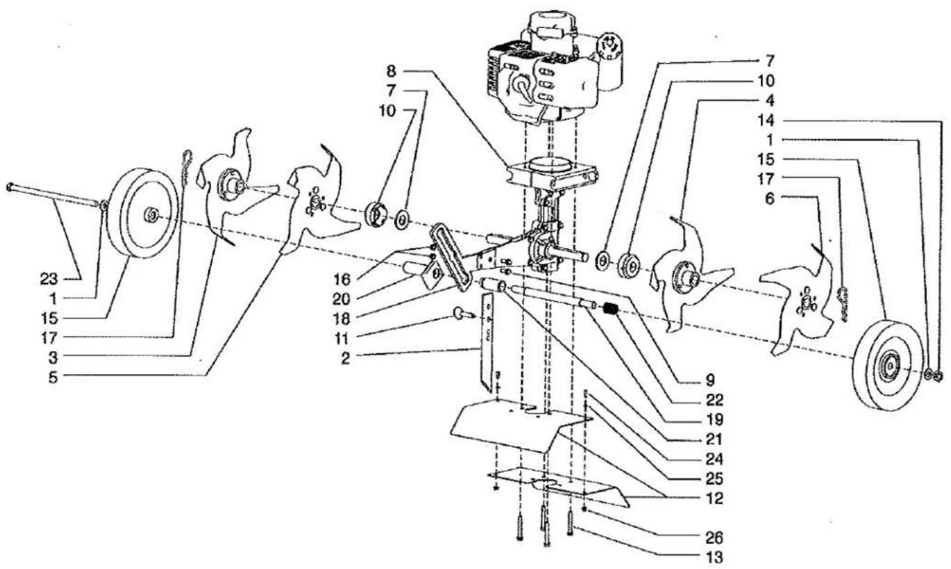
| KEY | PART # | DESCRIPTION | QTY |
| 1 | 2431 | WASHER, 10MM NARROW FLAT | 2 |
| 2 | 4600 | DRAG BAR | 1 |
| 3 | 4601 | TINE "A" RIGHT OUTSIDE | 1 |
| 4 | 4602 | TINE "C" LEFT INSIDE | 1 |
| 5 | 4603 | TINE "B" RIGHT INSIDE | 1 |
| 6 | 4604 | TINE "D" LEFT OUTSIDE | 1 |
| 7 | 4606 | WASHER, FIBER | 2 |
| 8 | 46138 | TRANSMISSION ASSEMBLY | 1 |
| 9 | 46142 | BOLT M6 X 1.0 X 15MM FLANGED HEX HD | 2 |
| 10 | 46144 | DUST CAP | 2 |
| 11 | 46145 | DETENT PIN 5/16 X 1-1/2" | 1 |
| 12 | 46146 | TINE SHIELD | 2 |
| 13 | 4625 | BOLT, M6 X 1.0 X 42MM FLANGED HEX HD | 4 |
| 14 | 4629 | NUT M10 X 1.5 CENTER LOCK HEX HD | 1 |
| KEY | PART # | DESCRIPTION | QTY. |
| 15 | 4634 | WHEEL | 2 |
| 16 | 4650 | NUT M6 X 1.0 FLANGED HEX HD | 2 |
| 17 | 4652 | HAIR PIN, 5/8-3/4 COTTER | 2 |
| 18 | 4673 | WHEEL HOLDER | 1 |
| 19 | 4674 | WHEEL TUBE | 1 |
| 20 | 4678 | GUIDE, WHEEL TUBE | 1 |
| 21 | 4684 | TUBE, WHEEL LOCK | 1 |
| 22 | 4685 | SPRING, WHEEL LOCK | 1 |
| 23 | 4687 | BOLT M10 X 1.5 X 225MM HEX HD | 1 |
| 24 | 4691 | BOLT, M4 X 0.7 X 10MM PHILLIPS PAN HD | 2 |
| 25 | 4692 | WASHER, M4 FLAT | 2 |
| 26 | 4694 | NUT M4 X 0.7 FLANGED HEX HD | 2 |
| -- | E43CCMCV | ENGINE 43CC CAT CONVERT | 1 |
| -- | E43MCEVE | ENGINE 43CC CAT CONVERT ELEC START | 1 |

WARNING:

The engine exhaust from this product contains chemicals known to the State of California to cause cancer, birth defects or other reproductive harm.
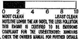
THE AIR INDEX OF THIS ENGINE IS 3
FEDERAL EMISSION CONTROL WARRANTY STATEMENT YOUR WARRANTY RIGHTS AND OBLIGATIONS
The U.S. Environmental Protection Agency (EPA) and Maruyama Manufacturing Company, Inc. are pleased to explain the emission control system warranty on your small nonroad engine. New 1997 and later model year small nonroad engines must be designed, built and equipped, at the time of sale, to meet the U.S. EPA regulations for small nonroad engines. The equipment engine must be free from defects in materials and workmanship which cause it to fail to conform with U.S. EPA standards for the first two years of engine use from the date of sale to the ultimate purchaser. Maruyama Manufacturing Company, Inc. must warrant the emission control system on your small nonroad engine for the period of time listed above provided there has been no abuse, neglect or improper maintenance of your small nonroad engine.
Your emission control system may include parts such as the carburetor or fuel injection system, the ignition system, and catalytic converter. Also included may be hoses, belts, and connectors and other emission related assemblies.
Where a warrantable condition exists, Maruyama Manufacturing Company, Inc. will repair your small nonroad engine at no cost to you, including diagnosis (if the diagnostic work is performed at an authorized dealer), parts, and labor.
MANUFACTURER'S WARRANTY COVERAGE:
1997 and later model year small nonroad engines are warranted for two years. If any emission-related part on your engine is defective, the part will be repaired or replaced by Maruyama Manufacturing Company, Inc. free of charge.
OWNER'S WARRANTY RESPONSIBILITIES:
(a) As the small nonroad engine owner, you are responsible for the performance of the required maintenance listed in your owner's manual.
Maruyama Manufacturing Company, Inc. recommends that you retain all receipts covering maintenance on your small nonroad engine, but Maruyama Manufacturing Company, Inc. cannot deny warranty solely for the lack of receipts or for your failure to ensure the performance of all scheduled maintenance. Any replacement part or service that is equivalent in performance and durability may be used in non-warranty maintenance or repairs, and shall not reduce the warranty obligations of the engine manufacturer.
(b) As the small nonroad engine owner, you should be aware, however, that Maruyama Manufacturing Company may deny you warranty coverage if your small nonroad engine or a part has failed due to abuse, neglect, improper maintenance or unapproved modifications.
(c) You are responsible for presenting your small nonroad engine to a Maruyama Manufacturing Company, Inc. service center as soon as a problem exists. The warranty repairs should be completed in a reasonable amount of time, not to exceed 30 days.
If you have any questions regarding your warranty rights and responsibilities, you should contact Maruyama U.S., Inc. at 1-866-783-7400.
COVERAGE
Maruyama Manufacturing Company, Inc. warrants to the ultimate purchaser and each subsequent purchaser that your small nonroad engine will be designed, built and equipped, at the time of sale, to meet all applicable regulations. Maruyama Manufacturing Company, Inc. also warrants to the initial purchaser and each subsequent purchaser that your small nonroad engine is free from defects in materials and workmanship which cause the engine to fail to conform with applicable regulations for a period of two years.
1997 and later model years, EPA requires manufacturers to small nonroad engines for two years. These warranty periods will begin on the date the small nonroad engine is purchased by the initial purchaser. If any emission-related part on your engine is defective, the part will be replaced by Maruyama Manufacturing Company, Inc. at no cost to the owner.
Maruyama Manufacturing Company, Inc. shall remedy warranty defects at any authorized Maruyama Manufacturing Company, Inc. engine dealer or warranty station. Any authorized work done at an authorized dealer or warranty station shall be free of charge to the owner if such work determines that a warranted part is defective. Any manufacturer-approved or equivalent replacement part may be used for any warranty maintenance or repairs on emission-related parts, and must be provided free of charge to the owner if the part is still under warranty, Maruyama Manufacturing Company, Inc. is liable for damages to other engine components caused by the failure of a warranted part still under warranty.
EPA's regulations do not include a parts list, but EPA considers emission-related warranted parts to include all the parts listed below. These warranted parts are: the carburetor assembly, the ignition coil assembly, the ignition rotor, the spark plug and the fuel tank.
MAINTENANCE REQUIREMENTS
The owner is responsible for the performance of the required maintenance as defined by the Maruyama Manufacturing Company, Inc. in the owner's manual.
LIMITATIONS
This Emission Control System Warranty shall not cover any of the following:
(a) repair or replacement required because of misuse or neglect, lack of required maintenance, repairs improperly performed or replacements not conforming to Maruyama Manufacturing Company, Inc. specifications that adversely affect performance and/or durability, and alterations or modifications not recommended or approved in writing by Maruyama Manufacturing Company, Inc., and
(b) replacement of parts and other services and adjustments necessary for required maintenance at and after the first scheduled replacement point.
CALIFORNIA EMISSION CONTROL WARRANTY STATEMENT YOUR WARRANTY RIGHTS AND OBLIGATIONS
The California Air Resources Board (CARB), and Maruyama Manufacturing Company, Inc. are pleased to explain the emission control system warranty on your 2010 and later small off-road engine. In California, new small off-road engines must be designed, built and equipped to meet the State's stringent anti-smog standards. Maruyama Manufacturing Company, Inc. must warrant the emission control system on your small off-road engine for the period of time listed above provided there has been no abuse, neglect or improper maintenance of your small off-road engine.
Your emission control system may include parts such as the carburetor or fuel injection system, the ignition system, and catalytic converter. Also included may be hoses, belts, and connectors and other emission related assemblies.
Where a warrantable condition exists, Maruyama Manufacturing Company, Inc. will repair your small off-road engine at no cost to you, including diagnosis, parts, and labor.
MANUFACTURER'S WARRANTY COVERAGE:
The 1995 and later small off-road engines are warranted for two years. If any emission-related part on your engine is defective, the part will be repaired or replaced by Maruyama Manufacturing Company, Inc.
OWNER'S WARRANTY RESPONSIBILITIES:
(a) As the small off-road engine owner, you are responsible for the performance of the required maintenance listed in your owner's manual.
Maruyama Manufacturing Company, Inc. recommends that you retain all receipts covering maintenance on your small off-road engine, but Maruyama Manufacturing Company, Inc. cannot deny warranty solely for the lack of receipts or for your failure to ensure the performance of all scheduled maintenance
(b) As the small off-road engine owner, you should be aware, however, that Maruyama Manufacturing Company may deny you warranty coverage if your small off-road engine or a part has failed due to abuse, neglect, improper maintenance or unapproved modifications.
(c) You are responsible for presenting your small off-road engine to a Maruyama Manufacturing Company, Inc. distribution center as soon as a problem exists. The warranty repairs should be completed in a reasonable amount of time, not to exceed 30 days.
If you have any questions regarding your warranty rights and responsibilities, you should contact Maruyama U.S., Inc. at 1-866-783-7400.
Emission System Parts
Exhaust Emission
Carburetor
Muffler
Catalytic Converter
Ignition Coil / Magneto
Spark Plug
Air Filter
EGR Valve (piston)
Fuel Filter
Evaporative Emission Fuel Tank
PARTS LIST
CER420
CONTENTS
- CRANKCASE, RECOIL STARTER .... 1 \~ 4
- CARBURETOR, FUEL TANK ....5\~8
2011.10.

MARUYAMA
P/N 623296
- CER420
CRANKCASE, RECOIL STARTER
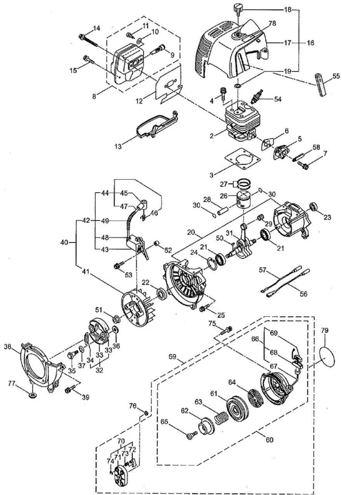
| Ref. No. | Part No. | Part Name | Q'ty | Remarks |
| 1-1 | 362300 | CER420 | 1 | 858954 (CE420/07) |
| 1-2 | 286278 | Cylinder | 1 | New gasket required |
| 1-3 | 285772 | Gasket | 1 | |
| 1-4 | 261246 | Cap Screw | 4 | M5x25 |
| 1-5 | 285778 | Insulator | 1 | New gasket required |
| 1-6 | 285779 | Gasket | 1 | |
| 1-7 | 265924 | Cap Screw | 2 | M5x25 |
| 1-8 | 286788 | Muffler Ass'y | 1 | Incl.9-11 |
| 1-9 | 262395 | Spark Arrester | 1 | |
| 1-10 | 284052 | Washer | 1 | M3 |
| 1-11 | 089530 | Tapping Screw | 1 | M3x10 |
| 1-12 | 285783 | Gasket | 1 | |
| 1-13 | 285784 | Under Cover | 1 | |
| 1-14 | 266713 | Cap Screw | 2 | M5x60 |
| 1-15 | 283315 | Screw | 1 | M5x12W-12 |
| 1-16 | 286916 | Top Cover Ass'y | 1 | Incl.17-19 |
| 1-17 | 285786 | Top Cover | 1 | |
| 1-18 | 262556 | Knob | 1 | |
| 1-19 | 286362 | Washer | 1 | M6 |
| 1-20 | 285789 | Crankcase | 1 | |
| 1-21 | 262658 | Bearing | 2 | #6202C3 |
| 1-22 | 262660 | Oil Seal | 1 | TC15357 |
| 1-23 | 262565 | Oil Seal | 1 | ISCD15257 |
| 1-24 | 012380 | Snap Ring | 1 | #35 |
| 1-25 | 261612 | Cap Screw | 4 | M5x30 |
| 1-26 | 285795 | Piston | 1 | |
| 1-27 | 262476 | Piston Ring | 2 | (2)Required |
| 1-28 | 262749 | Piston Pin | 1 | |
| 1-29 | 262659 | Bearing,Needle | 1 | KTV111414EG01B2 |
| 1-30 | 262479 | Clip,Piston Pin | 2 | |
| 1-31 | 285797 | Crankshaft/Conn.Rod Ass'y | 1 | |
| 1-32 | 262577 | Clutch Ass'y | 1 | Incl.33,34 |
| 1-33 | 282624 | Clutch Shoe | 2 | (2)required |
| 1-34 | 263615 | Spring,Clutch | 1 | |
| 1-35 | 282321 | Cap Screw | 2 | M8x1.25 |
| 1-36 | 262683 | Washer | 2 | 8x22xt1.2 |
| 1-37 | 262682 | Wave Washer | 2 | |
| 1-38 | 282285 | Fan Cover | 1 | |
| 1-39 | 261250 | Cap Screw | 4 | M5x20 |
| 1-40 | 285803 | Magneto Ass'y | 1 | Incl.41-49 |
| 1-41 | 286207 | Rotor/Fan | 1 | |
| 1-42 | 285804 | Ignition Coil Ass'y | 1 | Incl.43-49 |
| 1-43 | 285805 | Coil | 1 | |
| 1-44 | 285806 | Spark Plug Wire Ass'y | 1 | Incl.45-47 |
| 1-45 | 261074 | Plug Boot | 1 |
1. CER420
CRANKCASE, RECOIL STARTER
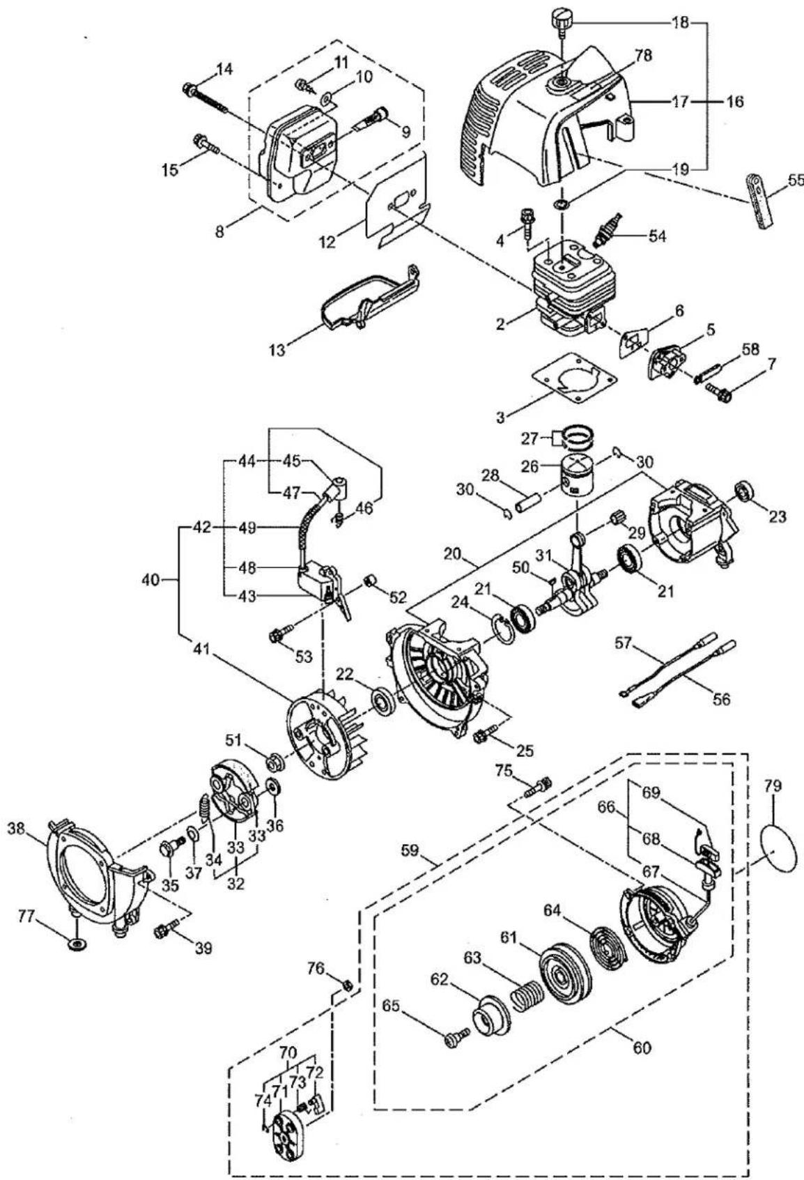
| Ref. No. | Part No. | Part Name | Q'ty | Remarks |
| 1-46 | 261075 | Connector | 1 | |
| 1-47 | 286273 | Spark Plug Wire | 1 | |
| 1-48 | 261072 | Cap | 1 | |
| 1-49 | 284759 | Insulator | 1 | |
| 1-50 | 261076 | Woodruff Key | 1 | 3x10 |
| 1-51 | 262731 | Nut,Rotor | 1 | M10 |
| 1-52 | 280381 | Spacer | 2 | |
| 1-53 | 261256 | Cap Screw | 2 | M4x25 |
| 1-54 | 285982 | Spark Plug | 1 | NGK BPM8Y |
| 1-55 | 286988 | Grommet | 1 | |
| 1-56 | 283735 | Wire, Coil | 1 | |
| 1-57 | 284541 | Wire,Lead | 1 | |
| 1-58 | 264588 | Clamp | 1 | |
| 1-59 | 285809 | Recoil Starter Ass'y | 1 | Incl.60-74 |
| 1-60 | 285810 | Starter Ass'y | 1 | Incl.61-69 |
| 1-61 | 286291 | Reel | 1 | |
| 1-62 | 286292 | Cam Plate | 1 | |
| 1-63 | 286293 | Damper Spring | 1 | |
| 1-64 | 280995 | Spiral Spring | 1 | |
| 1-65 | 286295 | Set Screw | 1 | |
| 1-66 | 286296 | Starter Rope Ass'y | 1 | Incl.67-69 |
| 1-67 | 286297 | Starter Rope | 1 | 3.8x1000 |
| 1-68 | 262633 | Starter Grip | 1 | |
| 1-69 | 262981 | Cap | 1 | |
| 1-70 | 285679 | Starter Pulley Ass'y | 1 | Incl.71-74 |
| 1-71 | 285680 | Starter Pulley | 1 | |
| 1-72 | 285681 | Pawl | 2 | |
| 1-73 | 285682 | Return Spring | 2 | |
| 1-74 | 262638 | E-Ring | 2 | |
| 1-75 | 268940 | Screw | 4 | M5x18 |
| 1-76 | 285736 | Nut | 1 | M8 |
| 1-77 | 285735 | Packing | 4 | |
| 1-78 | 287272 | Label | 1 | |
| 1-79 | 288469 | Label | 1 | CER420 |
2. CER420
CARBURETOR, FUEL TANK
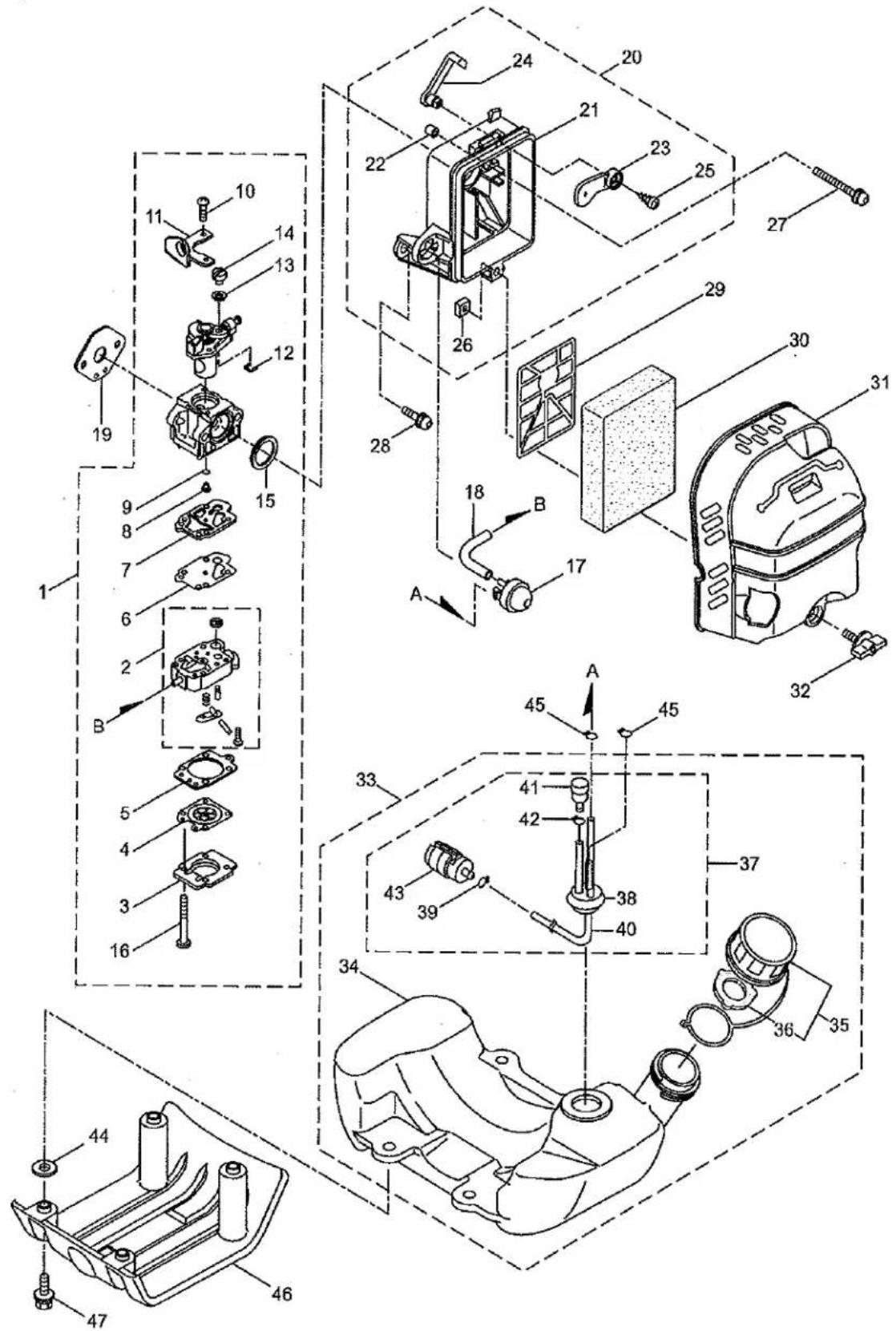
| Ref. No. | Part No. | Part Name | Q'ty | Remarks |
| 2-1 | 287021 | Carburetor Ass'y | 1 | Incl.2-16 New gasket required |
| 2-2 | 283124 | Pump Body | 1 | |
| 2-3 | 263726 | Cover Plate | 1 | |
| 2-4 | 283905 | Diaphragm, Meterring | 1 | |
| 2-5 | 263727 | Gasket | 1 | |
| 2-6 | 262994 | Diaphragm,Fuel Pump | 1 | |
| 2-7 | 282576 | Gasket | 1 | |
| 2-8 | 287061 | Main Jet | 1 | |
| 2-9 | 261871 | O-Ring | 1 | |
| 2-10 | 261875 | Screw | 2 | |
| 2-11 | 264677 | Bracket | 1 | |
| 2-12 | 261876 | E-Ring | 1 | |
| 2-13 | 264678 | Washer | 1 | |
| 2-14 | 261658 | Swivel | 1 | |
| 2-15 | 261657 | Packing | 1 | |
| 2-16 | 263737 | Screw | 4 | |
| 2-17 | 282299 | Pump | 1 | |
| 2-18 | 282512 | Fuel Pipe | 1 | |
| 2-19 | 282301 | Gasket | 1 | |
| 2-20 | 282302 | Case Ass'y | 1 | Incl.21-26 |
| 2-21 | 282303 | Case Body | 1 | |
| 2-22 | 282484 | Sleeve | 3 | |
| 2-23 | 282304 | Valve | 1 | |
| 2-24 | 282305 | Lever | 1 | |
| 2-25 | 269032 | Screw | 1 | |
| 2-26 | 269423 | Nut | 1 | |
| 2-27 | 261814 | Cap Screw | 2 | M5x50 |
| 2-28 | 264807 | Cap Screw | 1 | M5x16 |
| 2-29 | 282481 | Plate | 1 | |
| 2-30 | 282306 | Element | 1 | |
| 2-31 | 285814 | Cleaner Cover | 1 | |
| 2-32 | 281438 | Knob | 1 | |
| 2-33 | 285816 | Fuel Tank Ass'y | 1 | Incl.34-43 |
| 2-34 | 285817 | Fuel Tank | 1 | |
| 2-35 | 281564 | Fuel Tank Cap Ass'y | 1 | Incl.36 |
| 2-36 | 269377 | Gasket | 1 | |
| 2-37 | 286794 | Fuel Pipe Pick-up Ass'y | 1 | Incl.38-43 |
| 2-38 | 268065 | Grommet | 1 | |
| 2-39 | 261117 | Clip | 1 | |
| 2-40 | 262649 | Fuel Pipe | 1 | |
| 2-41 | 261590 | Breather | 1 | |
| 2-42 | 261117 | Clip | 1 | |
| 2-43 | 267328 | Fuel Filter Ass'y | 1 | |
| 2-44 | 285735 | Packing | 4 | |
| 2-45 | 261117 | Clip | 2 |
2. CER420
CARBURETOR, FUEL TANK
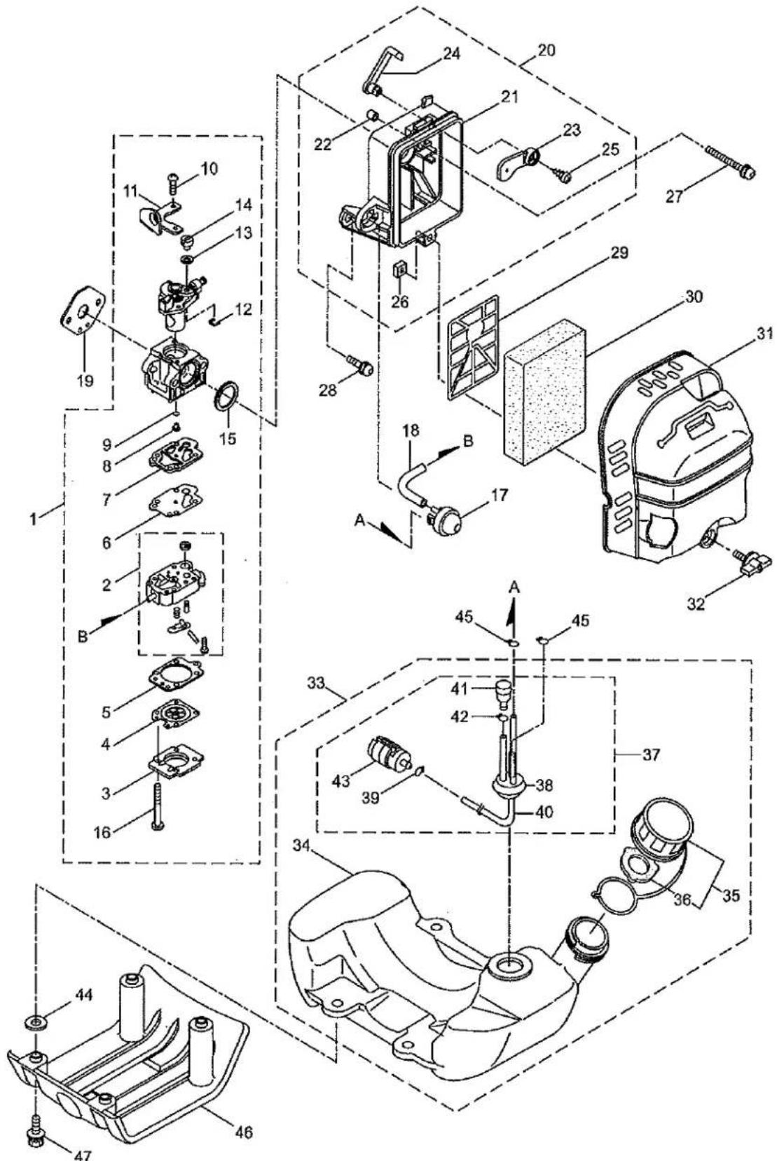
| Ref. No. | Part No. | Part Name | Q'ty | Remarks |
| 2-46 | 285819 | Stand | 1 | |
| 2-47 | 281714 | Cap Screw | 4 | M5x20 |
- THANK YOU AND CONGRATULATIONS...
- CONTENTS
- FEDERAL EMISSIONS INFORMATION
- REGISTRATION, SERVICE AND MAINTENANCE LOG
- WARNINGS AND SAFETY PRECAUTIONS
- OWNER'S RESPONSIBILITY
- SPECIAL MESSAGES
- BEFORE OPERATING ENGINE:
- WARNING
- CAUTION
- IMPORTANT
- Intended Use / Foreseeable Misuse
- GENERAL SAFETY RULES
- PRODUCT-SPECIFIC SAFETY RULES
- ENGINE SAFETY PRECAUTIONS
- Warning Carbon Monoxide Poisoning
- Preventing Carbon Monoxide Poisoning
- Gasoline Fires and Handling Fuel Safely
- DO NOT ALTER/MODIFY ENGINE:
- BURNS AND FIRES
- Prevention of Burns and Fires
- CHILDREN AND BYSTANDERS
- SERVICE
- SAFETY DECALS
- WARNING AND OTHER DECALS
- ASSEMBLY
- UNPACK MINI-CULTIVATOR
- OPERATION
- PREPARING ENGINE FOR STARTING
- MIXING FUEL AND FILLING FUEL TANK
- Mixing Fuel
- Filling Fuel Tank
- OPERATION TIPS
- Cold Starting Procedure
- Idle Speed Adjustment
- ADJUSTING WHEELS AND DRAG STAKE
- To adjust wheels up or down, SEE FIGURES 5 AND 6.
- To adjust the drag stake (SEE FIGURE 6):
- MAINTENANCE AND STORAGE
- STEPS FOR WORKING ON EQUIPMENT
- MINI-CULTIVATOR MAINTENANCE
- ENGINE MAINTENANCE
- TO PREVENT ACCIDENTAL STARTING:
- MAINTENANCE:
- Air Filter Cleaning
- Maintenance Interval
- Cylinder Cooling Fins
- Cooling Fin Cleaning
- Fuel Filter
- Fuel Filter Replacement
- Spark Plug
- Spark Plug Maintenance
- Spark Arrester
- Spark Arrester Maintenance
- Exhaust Muffler
- Muffler Maintenance
- TINE REMOVAL AND INSTALLATION
- To Remove Tines
- To Install Tines
- TRANSPORTING YOUR MINI-CULTIVATOR
- LONG-TERM STORAGE
- Steps for Long Term Storage
- PARTS BREAKDOWN
- HOOD & TINES PARTS EXPLOSION
- WARNING:
- FEDERAL EMISSION CONTROL WARRANTY STATEMENT YOUR WARRANTY RIGHTS AND OBLIGATIONS
- MANUFACTURER'S WARRANTY COVERAGE:
- OWNER'S WARRANTY RESPONSIBILITIES:
- COVERAGE
- MAINTENANCE REQUIREMENTS
- LIMITATIONS
- CALIFORNIA EMISSION CONTROL WARRANTY STATEMENT YOUR WARRANTY RIGHTS AND OBLIGATIONS
- Emission System Parts
- PARTS LIST
- CER420
- CRANKCASE, RECOIL STARTER
- CER420
- CARBURETOR, FUEL TANK
Brand : Maruyama
Model : MT42
Category : Tondeuse à fil