
3440A - Loudspeaker GENELEC - Free user manual and instructions
Find the device manual for free 3440A GENELEC in PDF.


| Product Type | Active Studio Monitor Speaker |
| Brand | Genelec |
| Model | 3440A |
| Dimensions (H x W x D) | 280 mm x 183 mm x 230 mm |
| Weight | 6.8 kg |
| Amplifier Power | 50 W + 30 W (Bi-amplified) |
| Frequency Response | 52 Hz – 20 kHz (-6 dB) |
| Maximum SPL | 105 dB |
| Woofer Size | 5.0 inches (127 mm) |
| Tweeter Size | 0.75 inches (19 mm) metal dome |
| Input Connectors | XLR balanced, RCA unbalanced |
| Input Impedance | 10 kΩ (balanced), 20 kΩ (unbalanced) |
| Power Consumption | Idle: 10 W, Max: 80 W |
| Power Supply | AC 100-240 V, 50/60 Hz |
| Protection Features | Overload protection, thermal shutdown |
| Mounting Options | Iso-Pod stand, wall mount with optional bracket |
| Recommended Usage | Studio monitoring, nearfield listening |
| Cleaning Instructions | Wipe with dry cloth; do not use solvents |
| Safety Certifications | CE, RoHS |
| Package Contents | Speaker, power cord, user manual |
Frequently Asked Questions - 3440A GENELEC
User questions about 3440A GENELEC
0 question about this device. Answer the ones you know or ask your own.
Ask a new question about this device
Download the instructions for your Loudspeaker in PDF format for free! Find your manual 3440A - GENELEC and take your electronic device back in hand. On this page are published all the documents necessary for the use of your device. 3440A by GENELEC.
USER MANUAL 3440A GENELEC
natural_image
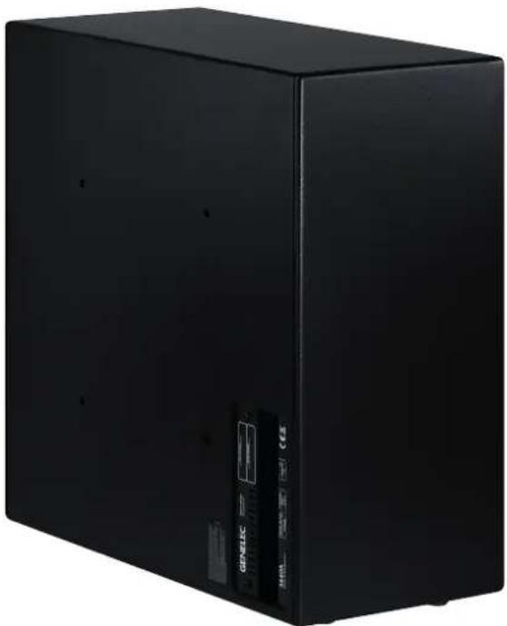
Two black and white rectangular electronic devices, one labeled 'GENELEC', shown against a white background (no additional text or symbols visible)Genelec 3440 Smart IP Subwoofer
natural_image
Black rectangular electronic device with a visible label and QR code (no readable text or symbols beyond branding)Introduction
The Genelec 3440A Smart IP subwoofer is a high performance subwoofer designed to support Genelec's 4400 Series Smart IP loudspeakers. It requires only one CAT cable to connect, making installation easy. The 3440A is powered using the standard Power-over-Ethernet (PoE) technology, using PoE+ or PoE standards. Using PoE+ is recommended for achieving the full performance of the 3440A. The proprietary internal power supply in 3440A delivers an impressive short-term SPL.
The cabinet is made from MDF with rounded corners and hardwearing textured surface. The driver is concealed inside an efficiency boosting cavity, which also protects it from physical damage. The driver is specially front loaded to improve both the passband efficiency and stopband rejection. Reflex ports are generously sized with radiused exits to prevent air chuffing noises.
The 3440A supports Genelec Smart IP technology, which provides scalable power, audio, and loudspeaker configuration. Supervision and calibration features are accessed via a standard CAT cable, offering integrators unrivalled power, flexibility, cost effectiveness, and simplicity of installation.
The 3440A has been designed for excellent sound quality over a very long lifetime. The 3340A is manufactured using certified sustainable methods, and all essential parts of the subwoofer can be recycled.
The 3440A subwoofer contains
• A highly efficient dedicated Class D power amplifier
- Switched-mode power supply technology offering high SPL output using standard PoE+ and PoE power supply with an IP switch or power injector
• Electronic system protection
• Audio-over-IP streaming input
• Balanced analogue line input
- Flexible room acoustic compensation tool set built in
- A cavity over the driver boosts the driver's efficiency and acoustically attenuates possible distortion components
The 3440A is designed for indoor use in temperatures 15-35 Celsius and non-condencing humidity
Unpacking
A Genelec 3440A package includes the following items. Check that nothing is missing or damaged in transit. If there is a problem with the product, contact your local Genelec dealer.
• 3440A subwoofer
- Euroblock connector for analogue audio (connected to the subwoofer)
Installation
When placed on the floor, the 3440A can be placed in an upright position (factory default) or flat on its side. If placed sideways, the base pads must be removed from the original threads and screwed into the thread inserts on the connector panel side to provide sufficient clearing for the cables and avoid scratching. Wall and ceiling mounting is possible using a Genelec 3440-400 bracket available as an accessory. In all cases, there must be a free space of 10 cm (4 in) in front of the reflex ports and all cabling must be routed so that there is no tension or pinching. When mounted on a wall or ceiling, the base pads can be removed for a cleaner appearance.
Cabling
To get started, connect an Ethernet cable from the PoE+ output in an IP switch to
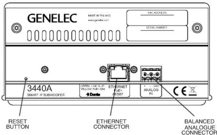
Figure 1. Connector panel of the 3440A
flowchart
graph TD
    A["8 port PoE enabled IP switch"] --> B["Unpowered ports"]
    A --> C["PoE+ powered ports"]
    A --> D["4 x PoE+ power"]
    D --> E["IP switch power supply"]
    F["3440A"] --> G["4435A or other Genelec IP loudspeakers"]
    G --> H["Mains in"]
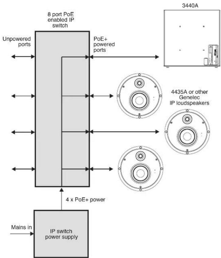
Figure 2. 3440A and three 4435A In-Ceiling loudspeakers powered with PoE+ IP switch.
the 3440A Ethernet port. Use CAT 5 or better flexible cable. When the balanced line input is used the subwoofer must still receive PoE power on the Ethernet cable.
The pin sequence for the line input is shown in Figure 5. The subwoofer powers up automatically.
To create a working system, you will need the following:
- An IP switch with a PoE+ (802.3at) output for the 3440A subwoofer or an IP switch with no PoE support and a PoE+ power injector
- CAT 5 or higher category Ethernet cable with RJ45 connectors
• AES67 or Dante audio-over-IP stream source - For 3440A setup and configuration, a computer running Windows 10 or Windows 11 operating system
• Genelec Smart IP Manager software - Dante Controller software. Additionally you may use Director or DDM to control and manage IP audio parameters
Figure 2 shows an example of powering the 3440A with a PoE+ enabled IP switch. With this method, the power budget available for all outputs connected to the IP switch must enable each 3440A to run at full PoE+ power. For 4 loudspeakers, the power supply must support 4 x PoE+ power level.
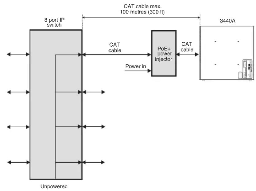
Figure 3 shows an example of powering the 3440A with a PoE+ power injector. This method enables the use of standard non-PoE IP switches. Each power injector must support full PoE+ power level into the device.
How PoE Power Management Works
The 3440A internal power supply stores power for peak output. This enables the output power to exceed the input power for short durations (Figure 4). Music and speech signals are dynamic. They contain high peaks above the average level. These peaks are supplied from the energy stored in the subwoofer power supply. The power supply has been dimensioned to work with audio and speech signals, including highly compressed wideband audio signals. The duration of peak output is limited more by the PoE supply and therefore Genelec recommends the use of PoE+ supply. When the audio signal demands more output power than available at the PoE power source, the amplifier scales down the output audio level keeping the audio quality excellent at all times.
PoE Budget Calculation
The 3440A supports automatic negotiation with the IP switch or IP power injector to set the PoE power level. However, in some cases it may be necessary to set the PoE power level in the switch manually.
There are several Power-over-Ethernet standards. The 3440A subwoofer supports the PoE+ standard but also works with the lower power PoE standard. When the 3440A also works with lower PoE power, the duration of high SPL output is shortened, and long continuous output signals play at smaller sound level than when the PoE+ power level is used. Genelec recommends using PoE+ power level with 3440A.
Each PoE supply device (IP switch or power injector) has a certain maximum output power capacity. This can limit the number of PoE outputs that can be set on. For 3440A subwoofer, calculate the output power for each output as 15 W for PoE and 30 W for PoE+. Ensure that the total power does not exceed the switch or power injector total power.
Example: IP switch total power is 150 W. You use PoE+ and four outputs are connected. The total output power is 4 × 30 W = 120 W. This is smaller than the capacity of the IP switch, 150 W. This scenario is acceptable.
PoE Cable Loss Calculation
There is power loss in the Ethernet cable. The reason for this is that the CAT cable conductor is thin and has considerable resistance. The power loss increases with increasing cable length. The maximum cable length is 100 meters (333 feet). Calculate the power loss in cable at 25 mW/m or 7.4 mW/ft. The 3440A will automatically adapt to the power loss in the cable, but lower input power will affect slightly the duration of the maximum SPL output. In order to minimize the cable loss and to maximize the duration at maximum SPL, consider using power injectors close to the loudspeakers or short cable runs.
Selection of IP Switch
Smart IP and 3440A are fully compatible with standard Ethernet and IP switch technology. Genelec recommends using gigabit speed managed IP switches with full PoE+ on each of the outputs intended for the 3440A subwoofer. Managed IP switches offer the ability to configure, manage and monitor the local area network, typically using a web browser user interface, and this helps in creating a well working system.
flowchart
graph LR
    A["8 port IP switch"] -->|CAT cable max. 100 metres (300 ft)| B["PoE+ power injector"]
    B -->|CAT cable| C["3440A"]
    D["Unpowered"] -->|Power in| B
Figure 3. 3440A powered by an IP PoE+ power injector
The IP switches should support Quality of Service (QoS) and be media ready. Differentiated services (DiffServ) typically implements QoS prioritization of IP traffic.
Smart IP works perfectly with all high-quality standard IP switches with these capabilities. Use of 100 Mbps IP switches is not recommended.
Network Structure
Genelec recommends always designing a network structure with star topology. Only one IP device (for example, one 3440A) should be connected at one port in an IP switch. IP device ports should not be daisy chained to several IP devices.
Audio-over-IP requires the use of cable-based LAN network. Low-latency uncompressed audio-over-IP streaming does not work over WLAN.
Inputs and Management
Audio-over-IP streaming supports unlimited number of channels in the playback system. These audio channels are automatically synchronized perfectly in time by the audio-over-IP streaming technology, forming a single playback system. The 3440A accepts AES67 and Dante audio-over-IP streams. The streams are set up with Dante Controller software. Each 3440A supports reproduction of one or the sum of two audio audio channels in the stream. The stream audio sample rate can range 32-96 kHz, with 16-24 bit resolution.
The 3440A contains one interface for Ethernet IP network connectivity. The network interface speed is 100 Mbps. The interface also allows Genelec's Smart IP Manager software to work on the 3440A. This software is available for AV installers at Genelec web site and runs on Windows 10 or Windows 11 computers. The software allows AV installers to configure an almost unlimited number of rooms, zones, loudspeakers and audio channels, and includes device discovery, a versatile room acoustic equalisation tool set, system organisation and status monitoring.
The 3440A contains an application programming interface (API) supporting control via third-party hardware, software or house automation. The API enables integration to all house and home automation systems. Detailed information about the API are provided in a separate document from Genelec.
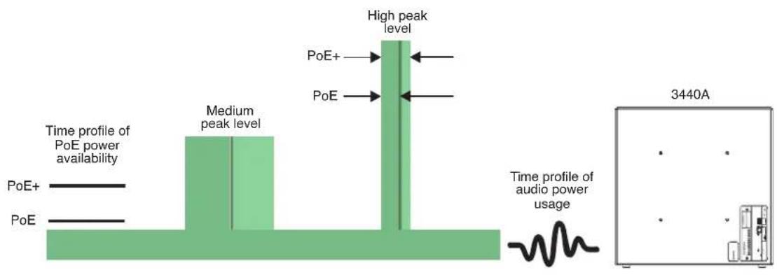
Figure 4. 3440A power supply enables high output level peaks exceeding the incoming PoE power level; the PoE standard limits the duration of the peaks
| Name Standard Power at switch Min. | power at 3440A | |
| PoE IEEE 802.3af-2003 15 W 13 W | ||
| PoE+ IEEE 802.3at-2009 30 W 26 W |
Table 1. PoE and PoE+ power levels
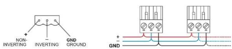
Figure 5. Balanced analogue input Euroblock connector pin-out (left) and parallel connecting of loudspeakers on the same analogue output using the input Euroblock connectors (right)
A balanced line input is available on 3440A besides the IP interface. The balanced line analogue audio input can be configured with Genelec Smart IP Manager software.
Setting Up Audio Streams
The 3440A can be set to receive one audio channel or a sum of two audio channels in a stream. In addition, using the Smart IP Manager software, 3440A can be set to also sum in the analog input signal as well. Audio stream setup is done by using Dante Controller software. Download the software from https://www.audinate.com/products/software/dante-controller.
Some audio streaming devices support only two flows, which is insufficient for a L+R stereo system with a subwoofer requiring three flows. In this case, a multicast stream can be created and the Left and Right channels assigned to it. This multicast stream is then subscribed to all loudspeakers and subwoofers in the system.
An AES67 audio stream supported by the subwoofer can have the maximum of 8 audio channels. The 3440A can select one audio channel or a sum of two channels in a stream.
The AES67 compatibility mode must turned ON to enable reception of AES67 streams. Follow these instructions:
- Double click on the loudspeaker to be configured. The Device View window opens
- Click AES67 Config -tab
- In the AES67 Mode panel, go to New: and select Enabled
- In the Reset Device panel, click Reboot to reboot loudspeaker with AES67 enabled
Analogue Input
An analogue audio input is provided using a screw-mount Euroblock connector. This enables easy connectivity and the option of connecting the balanced audio signal to several loudspeakers in parallel (see figure 8).
The input impedance of the analogue input is 10 kOhm. The pin sequence of the connector is shown in Figure 5. The number of loudspeakers that can be connected is set by the capability of the source device analogue output. The loudspeakers appear electrically in parallel, reducing the load impedance presented to the source device. Typically, 10 to 20 loudspeakers or subwoofers can be connected on one balanced line output.
Avoid connecting 3440A to the power amplifier outputs. If this must be done, use a balanced attenuator. Typically, an attenuation of about 20 dB is needed. Beware that some power amplifiers can provide a signal that exceeds the maximum voltage at the analogue input, and this can result in failure of the analogue input.
Genelec Smart IP Manager Software
Acoustic calibration, zone setup, input selection and loudspeaker management are done using Genelec Smart IP Manager software. This is a software intended for AV installers. Genelec recommends using the Application Programming Interface (API) inside the loudspeaker with house automation systems for the end-user control.
Download Smart IP Manager through your MyGenelec account, and follow the instructions to install.
ISS Autostart
The automatic power function ISS (Intelligent Signal Sensing) powers the subwoofer automatically down when it is not used and up again when the use resumes. ISS can be activated and adjusted with the Smart IP Manager software. Powering down to standby happens after a set time when playback has ended. Playback automatically resumes with an input signal exceeding the level configured using the Smart IP Manager. There is a slight delay in the automatic powering up. If this is undesirable, ISS can be disabled with Smart IP Manager.
The intended use of this subwoofer requires that the IP network interface is continuously enabled also in the standby mode. This enables the ISS to wake up with an API command or in response to IP audio stream. The power consumption in the ISS state for 3440A is 4 W. To save more power, the PoE+ power supply in the Ethernet switch or PoE injector can be turned off. However, subwoofer wakeup will then take slightly longer time and the subwoofer does not respond to any command on the IP network while it is not powered.
Reset Button
If necessary, the 3440A can be reset to factory settings by inserting a pin through a small hole on the connector panel (see fig.
1). Keep the button pressed for over ten seconds. Do not use excessive force. The subwoofer indicates that the reset process starts. Then you can release the button but do not disconnect power supplied by the Ethernet cable until the reset process is complete. Once the reset is complete, the subwoofer becomes available and active on the Smart IP Manager again. This typically takes less than one minute.
The factory setting for all acoustic settings is "OFF", sensitivity attenuator set to 0 dB, and delay set to 0 ms. These give a flat anechoic frequency response. Both the audio-over-IP stream and analogue inputs are selected to play. Audio stream settings are reset. With the factory settings, all that is needed to play audio is to provide a signal to the analogue input or to configure an
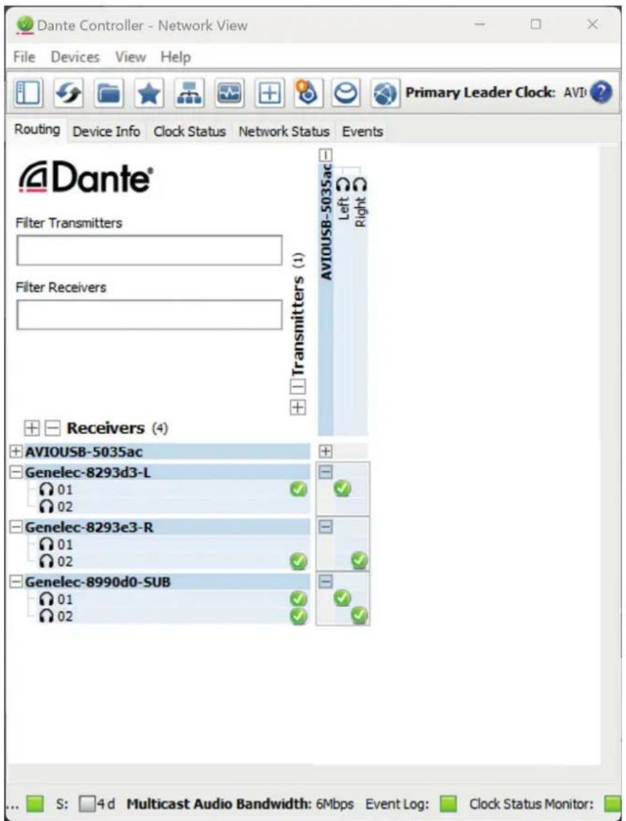
Figure 6. Setting up audio streams in the Dante controller
| Colour Indication | |
| Green Normal operation | |
| Green blink every 10 sec ISS power down state | |
| Yellow Muted | |
| Blinking yellow Device identification (controlled from Dante controller) | |
| Red Audio clipped, turn input level down | |
| Red Audio protection active, turn input level down | |
| Red Power failure, check POE budget | |
Table 2. 3440A LED Operating modes
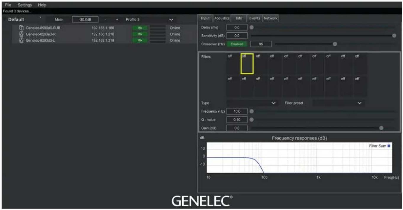
Figure 7. Smart IP Manager user interface with Acoustics tab selected
audio-over-IP stream in the stream input. Set stream again to resume normal streaming operation.
Status Indicator LED
The LED light on the front baffle has some status indication functions that are listed in Table 2.
Automatic Protection Circuits
The 3440 system has protection circuits against loudspeaker driver thermal overload and amplifier overheating. The protection system resets automatically so the user only has to turn the input level down to ensure that it does not reactivate.
Driver thermal overload protection protects the drivers from damage caused by prolonged overdriving with excessively high or distorted signal. If this occurs, the circuit automatically reduces playback volume. To avoid this, lower the listening volume if the sound becomes harsh and distorted at high sound pressure levels.
Maintenance
There are no user serviceable parts within the subwoofer. Any maintenance or repair should only be undertaken by qualified service personnel.
Bass Management
Bass management for the 3440A subwoofer and main loudspeakers in the system is done in Smart IP Manager software. Figure 7 shows the main screen of the software with a list of two loudspeakers and a subwoofer on the left. On the right side of the screen the Acoustics tab is selected. Adjustments made there apply to the speakers selected on the list on the left side of the screen. This allows making adjustments to individual loudspeakers or groups of loudspeakers.
The main adjustments for bass management are Delay, Sensitivity and Crossover. The following chapters give only a basic description of these functions, please refer to the Smart IP Manager Operating Instructions for more detail of their use.
Delay
The Delay adjustment sets a delay to a loudspeaker or a group of loudspeakers selected in the list. This can be used for matching the phase between the subwoofer and main loudspeakers.
Sensitivity
This adjustment can be used to match the playback level of the subwoofer and main loudspeakers.
Crossover
This adjustment sets a crossover frequency between the main loudspeakers and the subwoofer. It applies a low pass filter to the subwoofer and a matching high pass filter on the main speakers. A good starting point is 85 Hz. Select all loudspeakers and subwoofers on the list and set the frequency. This way it applies to all of them.
Safety Considerations
- Servicing and adjustment may only be performed by qualified service personnel.
• The subwoofer must not be opened. - Do not expose the subwoofer to water or moisture.
- Do not place objects filled with liquid, such as vases, on the subwoofer or near it.
- This subwoofer can produce sound pressure levels in excess of 85 dB, which may cause permanent hearing damage.
- Free flow of air on the connector panel side of the subwoofer is necessary to maintain sufficient cooling.
- The subwoofer is not disconnected from the power supply unless the CAT cable is removed from the subwoofer.
- Ensure that the mounting in the ceiling or wall is able to carry the full weight of the subwoofer in all circumstances, the
installations have been designed and are implemented according to the local safety regulations and follow principles of good workmanship. Using a safety wire is recommended.
- Genelec products and accessories come with instructions on the proper methods of installation and use. Follow these instructions.
WARNING!
This equipment is capable of delivering Sound Pressure Levels in excess of 85 dB, which may cause permanent hearing damage.
Guarantee
This product is supplied with a two year guarantee against manufacturing faults or defects that might alter the performance of the unit. Refer to supplier for full sales and guarantee terms.
line
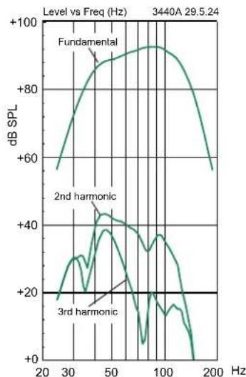
| Frequency (Hz) | Fundamental (dB SPL) | 2nd harmonic (dB SPL) | 3rd harmonic (dB SPL) | | -------------- | -------------------- | --------------------- | --------------------- | | 20 | ~60 | ~20 | ~20 | | 30 | ~80 | ~40 | ~20 | | 50 | ~90 | ~45 | ~20 | | 100 | ~95 | ~35 | ~20 | | 200 | ~60 | ~20 | ~20 |Figure 8. The curves above show the fundamental and harmonic distortion components of the 3440A in half space
SYSTEM SPECIFICATIONS
| Lower cut-off frequency, -6dB 35 Hz | |
| Upper cut-off frequency, -6dB 120 Hz | |
| Maximum short-term sine wave output on axis in half space, average 40 Hz to 85 Hz, at 1 m, using PoE+ power | ≥ 106 dB SPL |
| Maximum long-term RMS acoustic output in same conditions with band-limited random pink noise, at 1 m using PoE+ power (limited by driver unit protection circuit) | ≥ 101 dB SPL |
| Self-generated noise level in free space, at 1 m on the acoustical axis, A-weighted | ≤ 5 dBA |
| Harmonic distortion at 90 dB SPL at 1 m on axis in half space 40...85 Hz2nd3rd | ≤ 2%≤ 1% |
| Driver 165 mm (6.5 in) cone | |
| Weight 14.5 kg (32 lb) | |
| Dimensions H x W x DEnclosure without padsEnclosure height with pads (vertical orientation)Enclosure height with pads (horizontal orientation) | 475 x 475 x 220 mm (18 3/4 x 18 3/4 x 8 5/8 in)484 mm (19 1/16 in)229 mm (9 in) |
Maximum short-term output level is limited by the PoE technology being used and the crest factor of the audio signal. The stated values are typical for music and speech signals. Maximum long-term output level can be further limited by loudspeaker system protection. Genelec recommends using PoE+ whenever possible. Using lower-power PoE can limit short-term maximum and long-term maximum, depending on the characteristics of the signal being reproduced. User selectable filters can be set to positive gain. Positive gain must be used with care as it is possible to cause premature overload of the loudspeaker at specific frequencies.
INPUT / CROSSOVER SECTION
| Ethernet connection 100BASE-TX 1 x RJ45 | |
| Nominal SPL with 0 dBFS digital audio input at maximum sensitivity 130 dB SPL | |
| Audio-over-IP streaming formats AES67, Dante | |
| Analogue input, connector type 3 pin Euroblock | |
| Analogue input, Input impedance 10 kOhm, balanced | |
| Analogue input level for 100 dB SPL at 1 m -6 dBu | |
| Analogue input, maximum input signal 24 dBu | |
| Number of user-adjustable filters 20 | |
| User selectable filters, choice of function for each user-adjustable filter Parametric notchHigh frequency shelfLow frequency shelfBass roll-offBass tiltTreble tilt | |
| User selectable filters, parameter adjustment ranges for a notch filterGainQ-valueCenter frequency | -20...+2 dB0.1...2010 Hz...16 kHz |
| Sensitivity adjustment range | -60...0 dB |
| Delay adjustment range | 0...98 ms |
| Distributed bass management adjustment range | 50...120 Hz in 5 Hz steps |
| AMPLIFIER SECTION | |
| Bass amplifier output power, short-term 70 W | |
| Supply power at switch, power-over-EthernetPoE+ (Class 4)PoE (Class 3) | 30 W15.4 W |
| Supported PoE standardsPoE+ (supports signature and LLDP)PoE (supports signature) | IEEE 802.3atIEEE 802.3af |
| Ethernet cable specification 5, 5e, 6 | |
| Maximum Ethernet cable length 100 m (333 ft) | |
| Power consumption in idle 5 W | |
| Power consumption in ISS power-down mode 4 W | |
![200 mm [7 7/8 inch] 200 mm [7 7/8 inch] 4 M6 thread inserts. Maximum screw length 20 mm (3/4 inch)](/content/2026/05/854484/images/4892bb026c7a8555418c8d4b6eb11d6dff0f9d40defabeddfcd9a3ea197ad536.jpg)
![220 mm [8 11/16 inch]](/content/2026/05/854484/images/a0727a29d5748e745d19a610562ad9049108b413c4d6113d459ed092da60d6fe.jpg)
![475 mm [18 11/16 inch] 475 mm [18 11/16 inch] 8 mm [5/16 inch]](/content/2026/05/854484/images/d0f59dbcec18c8dc8c26c117cc9e18d19898162834ecc342773410f296d71583.jpg)

natural_image
Empty rectangular frame with black border (no text or symbols)Figure 8. Dimensions of the 3440A
Genelec Document D0219R001. Copyright Genelec Oy 4.2024. All data subject to change without prior notice
www.genelec.com
GENELEC®
International enquiries:
Genelec, Olvitie 5
FIN-74100, lisalmi, Finland
Phone +35B 17 83BB1
Fax +358 17 812 267
Email genelec@genelec.com
In the U.S. please contact:
Genelec, Inc., 7 Tech Circle
Natick, MA 0176D, USA
In China please contact:
Beijing Genelec Audio Co.Ltd
Room 101, Building B33,
Universal Business Park,
No.10 Jiuxianqiao Road,
Chaoyang District,
100015 Beijing, China
Phone +86 (10) 5823 2014
+86 400 700 1978
Email genelec.china@genelec.com
In Japan, please contact:
Genelec Japan Inc.
2-22-21 Akasaka, Minato-ku
07-0052, Tokyo
Phone +81-3-6441-0591
genelec.japan@genelec.com
Email genelec.japan@genelec.com
In Sweden please contact
Genelec Sverige
Tureholmsvägen 12
125 35 Älvsjö
Sweden
Phone +46 8 449 5220
Email sweden@genelec.com

- Genelec 3440 Smart IP Subwoofer
- Introduction
- Unpacking
- Installation
- Cabling
- How PoE Power Management Works
- PoE Budget Calculation
- PoE Cable Loss Calculation
- Selection of IP Switch
- Network Structure
- Inputs and Management
- Setting Up Audio Streams
- Analogue Input
- Genelec Smart IP Manager Software
- ISS Autostart
- Reset Button
- Status Indicator LED
- Automatic Protection Circuits
- Maintenance
- Bass Management
- Delay
- Sensitivity
- Crossover
- Safety Considerations
- WARNING!
- Guarantee
Brand : GENELEC
Model : 3440A
Category : Loudspeaker