
FEV150 - Meter FLUKE - Free user manual and instructions
Find the device manual for free FEV150 FLUKE in PDF.


| Product Type | EV Charging Station Analyzer |
| Model | FEV150 |
| Brand | Fluke |
| Plug Types Included | Type 1 (SAE J1772) and Tesla type plug |
| Display | High-visibility industrial-quality LCD |
| Power Supply | 4 AA batteries (not included) |
| Memory | Internal memory for test results |
| Connectivity | Bluetooth for TruTest software transfer |
| Test Functions | PE Pre-Test, Visual Inspection, Earth Bond, Insulation, Loop/Line Impedance, 30 mA RCD Trip, 6 mA RDC-DD Trip, Mains Voltage/Phase Sequence, Nominal Voltage, GFCI Trip, Control Pilot, Proximity Pilot, Error Test |
| Measurement Terminals | L1 (Live), L2/N (Neutral/Second Live), PE (Protective Earth) |
| Plug Connection Port | For Type 1, Type 2, or Tesla type plugs |
| Accessories Included | TPAK magnetic strap, carrying case |
| Software Compatibility | TruTest desktop software for reports and firmware updates |
| Warranty | 2 years from date of shipment |
| Standards Compliance | Designed to test AC EV charging stations per industry standards |
| Maintenance | Clean case with damp cloth and mild detergent; replace batteries as needed |
| Safety Features | PE Pre-Test for hazardous voltage detection; high voltage warning indicator |
| Operating Environment | Indoor/outdoor, handheld use |
Frequently Asked Questions - FEV150 FLUKE
User questions about FEV150 FLUKE
0 question about this device. Answer the ones you know or ask your own.
Ask a new question about this device
Download the instructions for your Meter in PDF format for free! Find your manual FEV150 - FLUKE and take your electronic device back in hand. On this page are published all the documents necessary for the use of your device. FEV150 by FLUKE.
USER MANUAL FEV150 FLUKE
EV Charging Station Analyzer
Users Manual
LIMITED WARRANTY AND LIMITATION OF LIABILITY
Each Fluke product is warranted to be free from defects in material and workmanship under normal use and service. The warranty period is 2 years and begins on the date of shipment. Parts, product repairs, and services are warranted for 90 days. This warranty extends only to the original buyer or end-user customer of a Fluke authorized reseller, and does not apply to fuses, disposable batteries, or to any product which, in Fluke's opinion, has been misused, altered, neglected, contaminated, or damaged by accident or abnormal conditions of operation or handling. Fluke warrants that software will operate substantially in accordance with its functional specifications for 90 days and that it has been properly recorded on non-defective media. Fluke does not warrant that software will be error free or operate without interruption.
Fluke authorized resellers shall extend this warranty on new and unused products to end-user customers only but have no authority to extend a greater or different warranty on behalf of Fluke. Warranty support is available only if product is purchased through a Fluke authorized sales outlet or Buyer has paid the applicable international price. Fluke reserves the right to invoice Buyer for importation costs of repair/ replacement parts when product purchased in one country is submitted for repair in another country.
Fluke's warranty obligation is limited, at Fluke's option, to refund of the purchase price, free of charge repair, or replacement of a defective product which is returned to a Fluke authorized service center within the warranty period.
To obtain warranty service, contact your nearest Fluke authorized service center to obtain return authorization information, then send the product to that service center, with a description of the difficulty, postage and insurance prepaid (FOB Destination). Fluke assumes no risk for damage in transit. Following warranty repair, the product will be returned to Buyer, transportation prepaid (FOB Destination). If Fluke determines that failure was caused by neglect, misuse, contamination, alteration, accident, or abnormal condition of operation or handling, including overvoltage failures caused by use outside the product's specified rating, or normal wear and tear of mechanical components, Fluke will provide an estimate of repair costs and obtain authorization before commencing the work. Following repair, the product will be returned to the Buyer transportation prepaid and the Buyer will be billed for the repair and return transportation charges (FOB Shipping Point).
THIS WARRANTY IS BUYER'S SOLE AND EXCLUSIVE REMEDY AND IS IN LIEU OF ALL OTHER WARRANTIES, EXPRESS OR IMPLIED, INCLUDING BUT NOT LIMITED TO ANY IMPLIED WARRANTY OF MERCHANTABILITY OR FITNESS FOR A PARTICULAR PURPOSE. FLUKE SHALL NOT BE LIABLE FOR ANY SPECIAL, INDIRECT, INCIDENTAL OR CONSEQUENTIAL DAMAGES OR LOSSES, INCLUDING LOSS OF DATA, ARISING FROM ANY CAUSE OR THEORY.
Since some countries or states do not allow limitation of the term of an implied warranty, or exclusion or limitation of incidental or consequential damages, the limitations and exclusions of this warranty may not apply to every buyer. If any provision of this Warranty is held invalid or unenforceable by a court or other decision-maker of competent jurisdiction, such holding will not affect the validity or enforceability of any other provision.
Fluke Corporation
6920 Seaway Blvd
Everett, WA 98203
U.S.A.
Fluke Europe B.V.
P.O. Box 1186
5602 BD Eindhoven
The Netherlands
Table of Contents
Title Page
Introduction.... 1
Contact Fluke 1
Safety Information.... 2
The Product 2
Features.... 4
Display.... 5
Main Menu 7
Menu Controls.... 8
Test Menu 9
Set up a Test.... 9
Project List Menu 9
Create a Project 10
Add a Project.... 10
Delete a Project.... 10
Enter Project Client and Site Codes.... 10
Project Menu.... 11
Add a Station.... 11
Copy a Station 11
Edit a Station.... 12
Delete a Station.... 12
Configure a Station.... 13
Earth Bond Configuration (FEV350) 18
Connect the Plug.... 20
Connect the TPAK Strap 21
Station and Connection Point Tests.... 22
Function Buttons in Tests.... 23
Symbols on Test Screens 24
Do a Test 27
PE Pre-Test.... 27
Visual Inspection Test 28
How to do Tests.... 29
Earth Bond Tests.... 30
Insulation Input or Output Tests.... 30
Loop/Line Impedance Test 30
30 mA RCD Trip Test 31
6 mA RDC-DD Trip Test 31
Mains Voltage/Phase Sequence Test 31
Nominal Voltage Test.... 31
GFCI Trip Test.... 31
Control Pilot Test.... 32
Proximity Pilot Test.... 32
Error Test.... 32
Settings Menu 33
Manual CP Menu.... 34
Troubleshoot GFCI Menu 35
TruTest™ Software Menu 36
Maintenance.... 36
Clean the Product 36
Battery Replacement 37
Product Disposal 37
Introduction
The Fluke FEV150/FEV350 Electric Vehicle (EV) Charging Station Analyzer (the Product or Analyzer) is a handheld test instrument to test ac electric vehicle (EV) charging stations (the Station or EVSE).
The Product verifies the safety and functionality of the Station through a preset test sequence, including Control Pilot (CP) charge state analysis. The product is designed to test ac electric vehicle charging stations in accordance with industry standards.
Use the FEV150 with a:
- Type 1 plug to test a station with a fixed cable connector.
- Tesla type plug to test a station with a Tesla type connector.
Use the FEV350 with a:
- Type 2 plug to test a station with a fixed cable or socket-outlet connector.
- Type 1 plug to test a station with a fixed cable connector.
The FEV350 allows for full installation certification in combination with a compatible multifunction tester (MFT) such as the Fluke 1664 FC. See the users manual for the MFT for instructions on how to set up, zero, and use the MFT.
The Product shows images on a high-visibility, industrial-quality LCD screen. The Product saves data to the internal memory. Use TruTest™ desktop software to transfer the saved results from the Product to the TruTest software through a Bluetooth connection.
Use TruTest software to generate professional reports and update the firmware of the Product. To download TruTest software, go to: https://www.fluke.com/en-us/support/software-downloads/trutest-software-downloads.
This Users Manual shows English screens in examples and images of the FEV350 model.
Contact Fluke
Fluke Corporation operates worldwide. For local contact information, go to our website: www.fluke.com+1-425-446-5500 fluke-info@fluke.com
To register your product, or to view, print, or download the latest manual or manual supplement, go to our website.
Safety Information
General Safety Information is in the printed Safety Information document that ships with the Product and at www.fluke.com. More specific safety information is listed where applicable.
A Warning identifies hazardous conditions and procedures that are dangerous to the user. A Caution identifies conditions and procedures that can cause damage to the Product or the equipment under test.
The Product
Table 1 shows the items included with the Product as part of a kit or purchased separately.
Table 1. Prod uct
| FEV150FEV350 | ||
| Item Description Function | ||
| ① | FEV150/FEV350 The Product | |
| ② | TY1 Type 1 plug (FEV150) Use with a station with a fixed cable connector. | |
| ③ | Tesla type plug (FEV150) Use with a station with a Tesla type connector. | |
| ④ | TY1 Type 1 plug (FEV350) Use with a station with a fixed cable connector. | |
| ⑤ | Type 1 zero adapter (FEV350) | Attach to a Type 1 plug to zero the connector or the test leads. |
Table 1. Product (cont)
| Item Description Function | ||
| 6 | TY2 Type 2 plug (FEV350) Use | with a station with a socket-outlet or a fixed cable connector. |
| 7 | Type 2 zero adapter (FEV350) | Attach to a Type 2 plug to zero the connector or the test leads. |
| 8 | Fluke 1664 FC Multi-function tester (MFT) | Use with the FEV350 for specific tests. See Table 8. |
| 9 | TPAK Magnetic strap Use to attach the Product to a station with metal housing. See Figure 2. | |
| -- Carrying case Not shown. | ||
Features
Table 2 shows the features of the Product.
Table 2. Features
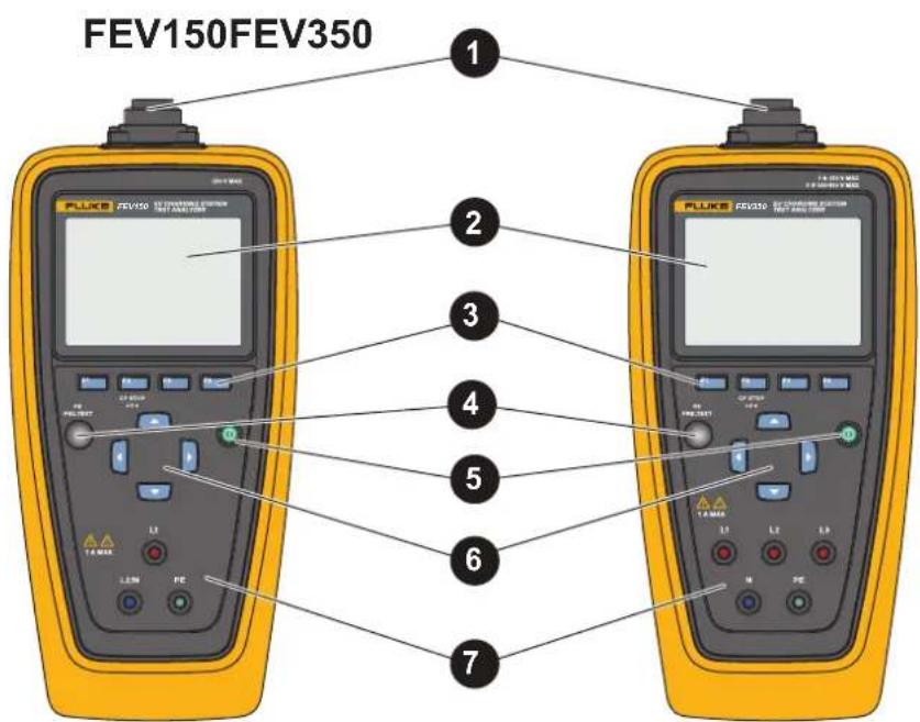
| Item Description Function | ||
| 1 | Plug connection port | Use to connect a Type 1, Type 2, or Tesla type plug to the Product. |
| 2 | Display See Display. | |
| 3 | Function buttonsF1(F1), F2(F2),F3(F3), F4(F4) | Do the action that shows on the display above the function button. |
| 4 | PE PRE-TEST sensor | Use to verify the station is properly grounded. See PE Pre-Test. |
| 5 | Power button | Turns on and off the Product. |
| 6 | Arrow buttons/ [IMAGE] | Use to navigate the menu to highlight a selection or change a numerical value. |
| 7 | Measurement terminals Use to connect test leads to the Product.FEV150:L1: Live wireL2/N: Neutral/second live wire for use with a split phase systemPE: Protective earth or groundFEV350:L1, L2, L3: Three line voltage phasesN: NeutralPE: Protective earth or ground | |
Display
When you turn on the Product for the first time, the language selection screen shows on the display.
To select a language:
-
Push ▲ / ▼ to highlight a language.
-
Push F1 (Select) to select the language for the user interface (UI).
Table 3 shows the items on the display.
Table 3. Display
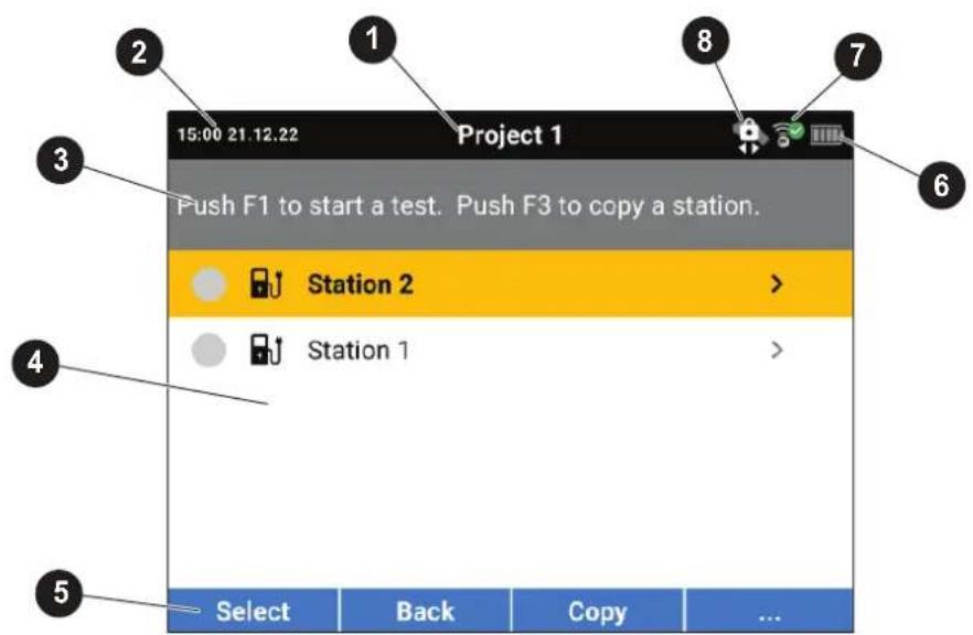
| Item Description Function | ||
| 1 | Name of the screen Name | of the screen you are in. |
| 2 | Time and date The time and date. | |
| 3 | Instruction subheader Shows the instructions for the screen. | |
| 4 | Screen content Main body of the screen. | |
| 5 | Soft keys Use with the function buttons to interact with the UI. | |
6 | Battery status icon ShowsBluetooth connection indicator. (FEV350) | the status of battery power.☐: Batteries have full power.☐: Replace batteries.Indicates the status of a Bluetooth connection between the Product and a compatible MFT. : The connection is in progress. : The connection is in progress. : The Product is connected. : The Product is connected. : The Product is not connected. : The Product is not connected. |
| 8 | Control pilot status indicator | Indicates when it is safe to disconnect the Plug from the Station. See Table 10. |
Main Menu
Table 4 lists the submenus available on the Main menu.
Table 4. Main Menu
| Submenu Function | ||
| [707Y] | Test | Select to add, view, or set up a project to do a test. See Test Menu. |
 | Settings | Select to set user preferences and view information about the Product. See Settings Menu. |
 | Manual CP Use to manually select states and values to troubleshoot a Station. See Manual CP Menu. | |
 | Trou bleshoot GFCI (FEV150) | Use to troubleshoot GFCI circuits. See Troubleshoot GFCI Menu. |
 | Tru Tes tTM Soft ware Use Bluetooth to connect the Product to TruTest software on a PC. See TruTestTM Software Menu | |
Menu Controls
Use the menu controls to navigate the menus, change settings, set up a project, and do a test. Table 5 lists the functions of the menu controls.
Some menus contain a scroll bar on the right side to indicate there are additional options or rows. To view additional options, push ▲ / ▼. The scroll bar indicates the location in the menu. The scroll bar is not a control.
Note
The arrow and function buttons, especially the F1 button, do different things based on where you are in the UI. Follow the directions carefully, or you might not configure the station as you intended. For example, some tests are not available or the results are adversely affected.
To change settings:
- Push ▲ / ▼ to highlight a menu.
- Push F1 (Select) to open an option menu.
- Push ▲ / ▼ to highlight a selection.
To change a setting that uses a toggle button, follow the directions carefully based on where you are in the UI.
- Push F1 (Select) to set the selection and go back to the previous screen, or push
F2 (Back) to cancel the changes and go back to the previous screen.
Table 5. Menu Controls
| Item Control Function | ||
| Additional menu, test, or step indicator | > | Indicates there is another menu or test.With a submenu or option menu highlighted, pushF1 (Select) to open the menu to adjust a setting, start a test, or to follow the on-screen instructions to connect the Product to an MFT or to TruTest software. |
| Bold text -- With a row highlighted, the selected option shows in bold text.For example:Connection Points 1 2 indicates there are two connection points selected.Push / to bold and select an option. | ||
| Toggle switch |   | Turns a feature on or off. Push / to toggle a feature.Indicates a feature is on or enabled.Indicates a feature is off or disabled. |
| Radio button selection indicator | [24TW][3474] | Indicates an option is selected.Indicates an option is not selected. |
Test Menu
Use the Test menu to set up and do tests.
Set up a Test
To set up a test, use the project list menu to create a project, the project menu to add a station to a project, and the station configuration menu to configure a station.
Project List Menu
Use the Project List menu to manage projects.
Create a Project
To create a project:
- Highlight the Test menu, and push F1 (Select).
The Project List menu shows with Add Project highlighted.
- Push F1 (Select) to create a new project.
Add a Project
To add a project:
- Highlight the Test menu, and push F1 (Select).
The Project List menu shows.
- With at least one project created, push F3 (Add) to add another project with the next sequential project number. The Project List can contain a maximum of 10 projects.
Delete a Project
To delete a project:
- Go to Test > Project List.
The Project List menu shows.
-
Push ▲ / ▼ to highlight a project to delete.
-
Push F4 (...) and highlight Delete.
-
Push F1 (Select) to delete the project.
-
Follow the on-screen instructions to confirm you want to delete the project.
Enter Project Client and Site Codes
To enter project client and site codes for a project:
- Go to Test > Project List.
The Project List menu shows.
-
Push ▲ / ▼ to highlight a project.
-
Push F4 (...) and highlight Enter Code.
- Push F1 (Select).
The Project List Enter Client and Site Code option menu shows.
- Push ◀ / ▶ to highlight a numerical field.
- Push ▲ / ▼ to increase or decrease a numerical value.
- With all fields complete, push List menu. F1 (Select) to save the codes and go back to the Project
Project Menu
Use the project menu to configure and manage stations.
Add a Station
To add the first station to a project:
- Go to Test > Project List.
The Project List menu shows.
- Highlight a project, and push F1 (Select) to open the project.
The Project menu shows with Add Station highlighted.
- Push F1 (Select) to create a new station.
The Station Configuration menu shows.
- Configure the station. See Configure a Station.
Copy a Station
To copy a station:
- Go to Test > Project List.
The Project List menu shows.
- Highlight a project, and push F1 (Select) to open the project.
The Project menu shows.
- Push ▲ / ▼ to highlight a station to copy.
Note
Fully configure the original station before you copy the station.
- Push F3 (Copy) to create a new station with the next sequential station number and the same configuration settings as the original station. A project may contain a maximum of 20 stations.
Edit a Station
To edit the configuration of a station:
- Go to Test > Project List.
The Project List menu shows.
- Highlight a project, and push F1 (Select) to open the project.
The Project menu shows.
-
Push ▲ / ▼ to highlight a station to edit.
-
Push F4 (...) and highlight Edit.
-
Push F1 (Select) to edit the station.
The Station Configuration menu shows.
- Configure the station as needed for the test. See Configure a Station.
Delete a Station
To delete a station:
- Go to Test > Project List.
The Project List menu shows.
- Highlight a project, and push F1 (Select) to open the project.
The Project menu shows.
- Push / to highlight a station to delete.
- Push F4 (...) and highlight Delete.
- Push F1 (Select) to delete the station.
- Follow the on-screen instructions to confirm you want to delete the station.
Configure a Station
To configure a station:
- Add a new station or select a station to edit.
The Station Configuration menu shows.
- Configure the Station as needed for the test.
a. On an FEV350, set the Station Type first.
b. Then, set the other settings in order from the top to the bottom of the list.
Table 7 is a list of the settings in the station configuration menu on the FEV350. Table 6 is a list of the settings in the station configuration menu on the FEV150.
Caution
A setting that is incompatible with a previously selected setting causes a change to the previous setting. Some settings can reduce the options available in other settings and the availability of some tests. Before you save the configuration, review all the settings.
- With the station configured, push F3 (Save) to save the station configuration settings and return to the project menu.
Table 6. Station Configuration Menu (FEV150)
| Setting Description | |
| Connection Points | Set the number of fixed cable or Tesla type connection points (the Connection Points) on the station. The maximum connection points on a station is two.The default setting isConnection Point 1.NoteYou cannot change the number of connection points in another menu. If only one connection point is selected on a station with two connection points, you need to configure the station again and do all the tests again. |
| Voltage Supply | Set the voltage value of the voltage supply of the station. The default setting is240 V.The Product uses the voltage value to determine the results of Nominal Voltage and Control Pilot tests SeeNominal Voltage TestandControl Pilot Test. |
| Max Charge Current | Set the maximum charge current of the station. The default setting is32 A.NoteIf the max charge current of the station does not show in the list, select the most appropriate max charge current to use for tests.Use the max charge current setting to determine:The test measurements and results in a Proximity Pilot test. SeeProximity Pilot Test.The reported station amperage in a Control Pilot test. SeeControl Pilot Test. |
| Ventilation required | When disabled, the Product uses Control Pilot states A, B, and C as the active charge state. Control Pilot state D shows as an error. The default setting is disabled.When enabled, the Product uses Control Pilot states A, B, and D as the active charge states. |
Table 7. Station Configuration Menu (FEV350)
| Setting Description | |
| Station Type | Set the station type. The default setting isType 2 with cable.Type 1 with cable:L2 and L3 measurements are not available on tests. 3 is not available as a Voltage Supply option.Uses32 A Max Charge Current for Proximity Pilot tests.Max Cable Ampacityis not available on tests.Type 2 with cable:Uses Max Cable Ampacityfor Proximity Pilot tests.Type 2 with socketMax Cable Ampacityis not available on tests. |
| Connection Points | Set the number of socket outlet or fixed cable connection points (the Connection Points) on the Station. The maximum connection points on a station is two.The default setting isConnection Point 1.NoteYou cannot change the number of connection points in another menu. If only one connection point is selected on a station with two connection points, you need to configure the station again and do all the tests again. |
| Protection Class | Set the protection class of the housing of the station. The default setting isProtection Class I.WithProtection Class IIselected:In the Earth Bond Limits menu, Test Point does not show as an option.In a station test menu,Earth Bond Housingtest does not show, and the Product does not do a Earth Bond Housing test. |
| Earth Bond Limit | Set the limit in ohms to use on an earth bond test. See Earth Bond Configuration (FEV350). The default setting is 0.3 Ω.Test Point: Use with an MFT to do an Earth Bond Housing test on the station.With Protection Class II selected, Test Point does not show.Connection Point: Use with an MFT to do an Earth Bond Connection Point test. Shows the number of connection points set. |
| Mains System | Set the mains type of the station. The default setting is TN.The mains type of the station works together with the voltage set in Voltage Supply to define the current limits used in a Loop/Line Impedance and time limits used in a 30 mA RCD Trip tests. See Loop/Line Impedance Test and 30 mA RCD Trip Test. |
| Voltage Supply Set | the voltage value and number of phases of the voltage supply of the station. The default setting is 230 / 400 V 3 φ.With 1 φ selected, L2 and L3 measurements are not available on tests.See Insulation Input or Output Tests, Loop/Line Impedance Test. and Mains Voltage/Phase Sequence Test.The Product uses the voltage value to determine the results of:Mains Voltage/Phase Sequence tests. See Mains Voltage/Phase Sequence Test.30 mA RCD Trip tests. 30 mA RCD Trip Test. |
| Fuse Type and Rating | Set the fuse type of the station. Then set the fuse rating of the fuse type.The default fuse type is LS C. The default fuse rating is 20 A.NoteIf the fuse type or rating of the station does not show in the list,select the most appropriate fuse type or rating to use for tests.Use with an MFT to do a Loop/Line Impedance test on a connection point.The fuse type and rating uses standards to determine the limit for Loop/Line Impedance tests. See Loop/Line Impedance Test. |
| Max Charge Current | Set the maximum charge current of the station. The default setting is 16 A.NoteIf the max charge current of the station does not show in the list,select the most appropriate max charge current to use for tests.Use the max charge current setting to determine:The test measurements and results in a Proximity Pilot test. See Proximity Pilot Test.The reported station amperage in a Control Pilot test. See Control Pilot Test. |
| Max Cable Ampacity | With the station type set as Type 2 fixed cable, set the maximum amperage or current capacity of the cable. The default setting is 32 A.The Product uses the maximum cable ampacity to determine the test measurements and results of a Proximity Pilot test. See Proximity Pilot Test. |
| RCD Type | Set the RCD type to enable the subtests in a 30 mA RCD Trip test. The default setting isType A /F 30 mA.With the RCD type set toNone, the 30 mA RCD Trip test does not show.The RCD type can affect RCD test steps and the shape of the RCD test current. |
| RDC-DD | Disable (○) the feature if the station does not have a 6 mA RDC-DD.With the feature disabled, the 6 mA RDC-DD test does not show in the test menu.Enable (○) the feature if the station has a 6 mA RDC-DD. With the feature enabled, the 6 mA RDC-DD test shows in the test menu. The default setting is enabled.With RDC-DD enabled:The RCD type affects RCD test steps and the shape of the RCD test current.Loop measurements between L1, L2, or L3 and PE are not available. |
| Ventilation required | When disabled, the Product uses Control Pilot states A, B, and C as the active charge state. Control Pilot state D shows as an error. The default setting is disabled.When enabled, the Product uses Control Pilot states A, B, and D as the active charge states. |
Earth Bond Configuration (FEV350)
Set the limit to use on Earth Bond Housing tests. Copy a test point to assign each metal piece on the station housing an individual test point. The maximum number of earth bond housing test points is 10. The default number of test points is one. If needed, delete a test point. Use the first Earth Bond Housing test point to measure the earth bond connection between the Station and the distribution panel.
Set the limit to use on Earth Bond Connection Point tests. To change the number of socket-outlet or vehicle connection points on the station, see Connection Points in Table 7.
To configure a station to do an Earth Bond test:
- Go to Test > Project List.
- Select a project, select a station, and highlight Earth Bond Limits.
- Push F1 (Select).
The Earth Bond Limits menu shows.
- Push ▲ / ▼ to highlight a test point or a connection point.
- Push F1 (Select).
The Earth Bond Limit menu shows.
- Manually set the limit:
a. Push ◀ / ▶ to highlight a field.
b. Push ▲ / ▼ to increase or decrease the numeric value.
c. Push F1 (Select) to set the limit.
- If necessary, add another Earth Bond Housing test point:
a. Push ▲ / ▼ to highlight a test point to copy.
b. Push F3 (Copy) to create another test point with the same limit setting as the original test point.
- To delete an Earth Bond Housing test point, highlight a test point, and push F4 (Delete).
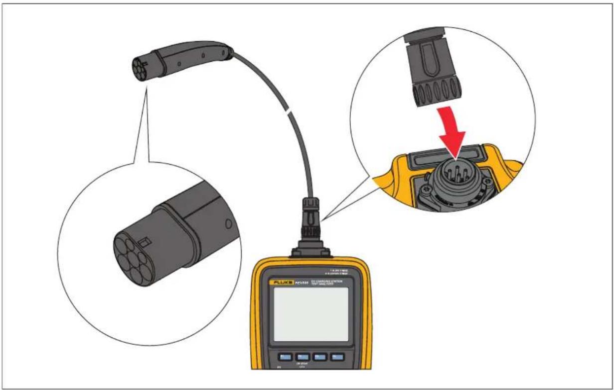
Connect the Plug
Figure 1 shows how to connect a plug to the Product.
Figure 1. Connect the Plug
Connect the TPAK Strap
Warning
Configure a station and do a PE Pre-Test and visual inspection test before you attach the TPAK strap to the station housing. See Do a Test.
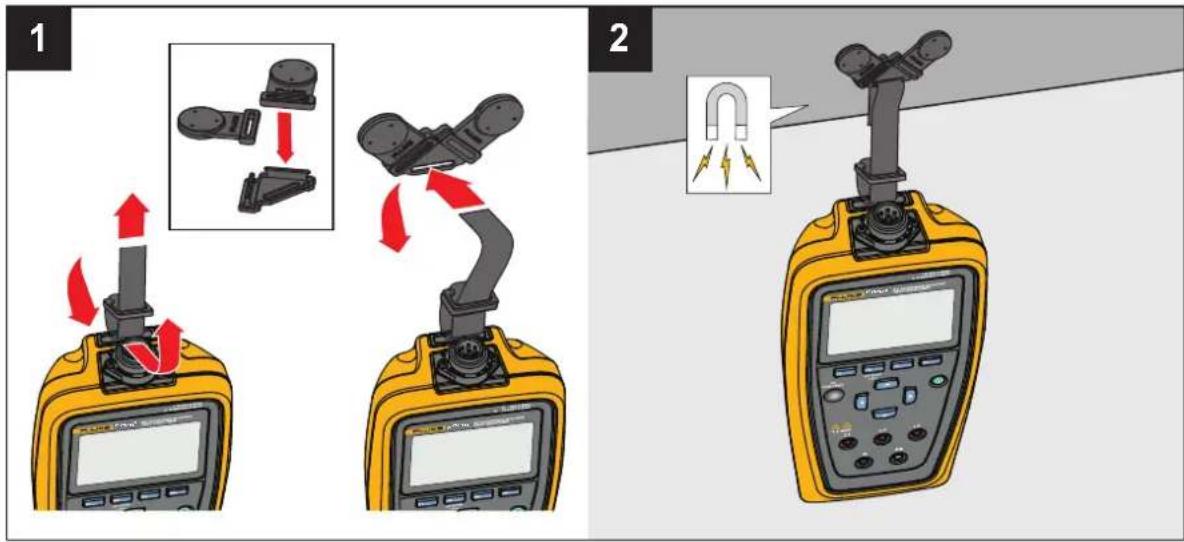
Figure 2 shows how to connect the TPAK magnetic strap to the Product.
Figure 2. Connect the TPAK Strap
Station and Connection Point Tests
Warning
Configure a station and do a PE Pre-Test and visual inspection test before you touch the station housing or do any other station or connection point tests.
Table 8 lists the Station and Connection Point tests the Product can do and notes which test requires an MFT to do the test. To connect the Product to an MFT, see Table 12.
Table & Tests
| Test FEV150 FEV350 Requires an MFT | |||
| Station Test | |||
| PE Pre-Test ● | ● | ||
| Visual Inspection ● | ● | ||
| Earth Bond Housing ● | ● | ||
| Insulation Input ● | ● | ||
| Connection Point Test | |||
| Earth Bond Connection Point | ● | ● | |
| Insulation Output | ● | ● | |
| Loop / Line Impedance | ● | ● | |
| 30 mA RCD Trip | ● | ||
| 6 mA RDC-DD Trip | ● | ||
| Mains Voltage / Phase Sequence | ● | ||
| Nominal Voltage | ● | ||
| GFCI Trip Test | ● | ||
| Control Pilot | ● | ● | |
| Proximity Pilot | ● | ● | |
| Error Test | ● | ● | |
Function Buttons in Tests
Table 9 shows some of the actions the function buttons may do. Not all functions are available in all tests.
Table 9. Function Buttons in Tests
| Button Function | |
 | Select: With a test highlighted, push to open the main menu of the test.Start: Push to start a test.Next: Push to do the next step of a test. |
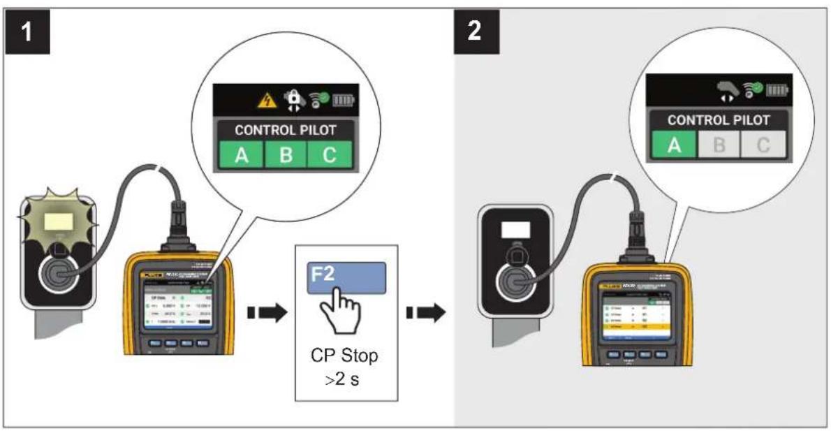
 | Back: Push to go back to the previous screen and not save changes or test results.Stop: Push to stop the test, go back to the main menu of the test to do the test again, and not save the results.Exit: Push to stop the test, go back to the station test menu., and not save the results.CP Stop >2 s: Push and hold for >2 s to turn off the control pilot, turn off the Station, and not save the results. See Figure 3. |
 | Results: Push to view the results of a test. |
 | ...: Push to show additional options.: Push to indicate a test is not applicable. |
Figure 3. CP Stop
flowchart
graph LR
    A["Device 1"] --> B["Control PILOT"]
    B --> C["F2: Click hand pointing to CP Stop >2 s"]
    C --> D["Control PILOT"]
    D --> E["Output"]
Symbols on Test Screens
Table 10 describes the symbols that can be on a test screen.
Table 10. Symbols on Test Screens
| Symbol Description FEV150 FEV350 | |||
| Test visibility | |||
 | Indicates a Station or Connection Point test menu is not open. Push F1 to open the menu to view the tests. | ● | ● |
 | Indicates a Station or Connection Point test menu is open. Not all tests may show on the display. Push F1 to hide the tests and see more items on the display. | ● | ● |
| Symbol | Description | FEV150 | FEV350 |
| MFT required | |||
 | Indicates a test requires a compatible MFT. To connect the Product to an MFT, see Table 12. | ● | |
| Test status | |||
 | A test is not started, or a test is in process and not completed. | ● | ● |
 | A test passed. ● ● | ||
 | A test failed. ● ● | ||
 | A test is not applicable. ● ● | ||
| Waveform indicator | |||
 | An ac test that starts at 0°. ● | ||
 | An ac test that starts at 180°. ● | ||
 | A halfwave test that starts at 0°. ● | ||
 | A halfwave test that starts at 180°. | ● | |
 | A dc test that starts at 0°. ● | ||
 | A dc test starts at 180°. ● | ||
 | An RCD or RDC-DD ramp current test that may start at 0° or 180°. | ● | |
| RCD/RDC-DD or GFCI circuit status | |||
 | Indicates an RCD or RDC-DD device has not been tripped. | ● | |
| Indicates a GFCI device has not been tripped. ● | |||
| Phase direction indicators | |||
 | Indicates clockwise rotation. | ● | |
 | Indicates counter-clockwise rotation. | ● | |
| Symbol Description FEV150 FEV350 | |||
| Earth bond test current indicator | |||
| Ω± | Indicates an earth bond test was taken with positive and negative test current. The Product shows the result of the one with the greatest resistance value. | ● | |
| Voltage detection indicator | |||
| L1 | Indicates the Product detects phase L1. ● ● | ||
| L2 | Indicates the Product detects phase L2. ● ● | ||
| L3 | Indicates the Product detects phase L3. ● | ||
| Control Pilot state indicator | |||
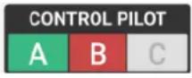 | Shows the state of the control pilot.Gray indicates the control pilot signal is off for the CP state.Yellow indicates the control pilot signal is in the process to determine if the signal is within the limits of the CP state.Green indicates the control pilot signal is within the limits for the CP state.Red indicates the control pilot signal is not within the limits for the CP state. | ● | ● |
| CP activity status | |||
 | Control Pilot is in state B, C, or D. Do not disconnect the plug from the Station. | ● | ● |
 | Control Pilot is in state A. You may disconnect the plug from the station. | ● | ● |
| High voltage indicator | |||
 | WARNING. HAZARDOUS VOLTAGE. Risk of electric shock. | ● | ● |
Do a Test
Warning
Configure a station and do a PE Pre-Test and visual inspection test before you touch the station housing or do any other station or connection point tests.
PE Pre-Test
Warning
Do not touch the housing of the charging station until the results show ≤50 V.
The PE Pre-Test is a safety feature of the Product. Do a PE Pre-Test to verify the protective earth (PE) conductor connects to the station and ground correctly before you do any other test.
The PE Pre-Test detects the presence of hazardous voltage on the Station housing and PE, but the test may not detect an open PE. An open PE is a PE connection that is not connected to ground and may be hazardous. An open PE can happen when the PE conductor is connected to phase or when PE is disconnected.
With incorrect connection to ground (for example, isolated placement of your body), the test result might not be accurate. Do not wear gloves.
To do a PE Pre-Test:
- Set up and select a station.
- Connect the Product to the charging station.
-
Highlight PE Pre-Test.
-
Push F1 (Select) to open the test menu.
-
Push F1 (Start) to start the test.
-
Touch and hold a bare finger to the PE PRE-TEST sensor (●) for 3 s.
-
Push F1 (Next) to view the result.
⚠ Warning
If the result shows >50 V, stop the test immediately. There may be hazardous voltage present at the PE terminal and metal parts of the charging station.
Note
It might be important to do this test again after the mains voltage to the Station turns on.
Visual Inspection Test
Make sure a PE Pre-Test passes, before you do a Visual Inspection test. Use a checklist to visually inspect a station for signs of damage or hazardous conditions that might need repair before you do other tests. The visual inspection list on the Product is an example of items you can inspect. See the documentation provided by the manufacturer of the Station for specific visual inspection requirements.
Warning
If a checklist item fails, make sure there are no hazardous conditions and that repairs are complete before you do any other station or connection point tests.
To do a visual inspection test:
- Push / to highlight Visual Inspection Test.
- Push F1 (Select) to open the test menu.
- Push ▲ / ▼ to highlight an item.
- Push the appropriate button to set an item on the checklist to pass, fail, or not applicable for a station. See Table 11.
Table 11. Checklist Item Functionality
| Button Description | |
 | Push to set a single item on the checklist to pass. Push and hold >2 s to set all items on the checklist to pass. |
 | Push to set a single item on the checklist to fail. Push and hold >2 s to set all items on the checklist to fail. |
 | Push to set a single item on the checklist to not applicable. Push and hold >2 s to set all items on the checklist to not applicable. |
How to do Tests
To do a test:
- If not done previously:
a. Set up and select a station.
b. Do a PE Pre-Test and a visual inspection test. See PE Pre-Test and Visual Inspection Test.
- If needed for the test, pair the Product with an MFT. See Table 12.
⚠ Warning
For tests that use an MFT, connect the test leads to the MFT and then to the Product.
Note
For tests that use an MFT, the Product shows the settings to use on the MFT in red. The settings on the Product change to green when the settings are set correctly on the MFT.
- Push ▲ / ▼ to highlight a Station or Connection Point test.
- Push F1 (Select) to open a test menu to do a test.
A test screen shows on the display.
-
If necessary, highlight a test.
-
Push F1 (Start) to start the test and overwrite existing results if √ or ✗.
-
Follow the instructions on the display to do the test.
If necessary while in a test, push F2 (Back) to go back to the previous screen, or push F2 (Stop) to stop the test and go back to the project and station test menu.
Earth Bond Tests
The tests require a compatible MFT and uses the limit set in the station configuration menu. See Configure a Station.
An earth bond housing test measures the resistance of the earth from the ground pin of the mains supply of the Station to the housing of the Station.
An earth bond connection point test measures the resistance of the PE connection from the mains supply of the Station to the Connection Points of the Station.
Insulation Input or Output Tests
An insulation input test measures the integrity of the insulation of the wires from the mains into the Station. An insulation output test measures the integrity of the insulation of the wires from the Station to the Product. The tests require a compatible MFT.
The tests use a fixed limit of 1 MΩ to determine the results.
Loop/Line Impedance Test
Loop and line impedance tests measure the impedance of the electrical system. The test measures the impedance and calculates the prospective fault current and earth fault current in the system to make sure sufficient current flows to open a breaker or fuse.
The test uses the limit set in the station configuration menu based on the fuse type and rating. See Configure a Station.
With RDC-DD set to ☐, the Product may run a loop and line impedance test.
With RDC-DD set to ☐, the Product runs a line test only.
With RDC-DD set to ☐, a loop impedance test causes the circuit of the RDC-DD to open.
30 mA RCD Trip Test
Trip Time: The test applies a ground fault or current imbalance to make sure a 30 mA RCD opens the circuit in the time listed in the standard based on the Mains System, Voltage Supply, and RCD Type set in the Station Configuration menu. See Configure a Station.
Trip Current: The test applies ground faults or current imbalance of different current levels to make sure a 30 mA RCD opens the circuit at the sufficient current listed in the standard based on the settings in the station configuration menu. See Configure a Station.
6 mA RDC-DD Trip Test
Trip Time: The test applies a ground fault or current imbalance to make sure a 6 mA RDC-DD opens the circuit in the time listed in the standard.
Trip Current: The test applies ground faults or current imbalance of different current levels to make sure a 6 mA RDC-DD opens the circuit at the sufficient current listed in the standard.
Mains Voltage/Phase Sequence Test
The mains voltage test measures the voltage and frequency the Station outputs to the Connection Points. In a test of a three phase system, the test also determines if the phase rotation is in the correct sequence.
Nominal Voltage Test
The nominal voltage test measures the voltage and frequency the Station outputs to the Connection Points.
GFCI Trip Test
In North America, a station is required to use a GFCI device to protect the user. On many stations, after the GFCI device trips, the GFCI device automatically resets to protect the user. When you push the GFCI button on the Station, the Station should terminate the charging cycle.
Control Pilot Test
The Control Pilot test makes sure the Control Pilot signal from the Station has the correct voltage, frequency, and duty cycle for the Station Type set in the station configuration menu. See Configure a Station.
The test measures the CP signal of the Station while the Station changes from CP state A to CP state C and makes sure the signal meets the limit in the standard.
The test converts the duty cycle to I_max . The Product saves up to 10 changes in CP state and output voltage L1/L2/L3 on the FEV350 and L1/L2 on the FEV150.
With a test complete, the display shows a summary list of the events.
To see more information about the results:
-
To see the details of each event, push F3 (Results).
-
To view the results in a table or as a curve diagram, push ▲/▼.
Proximity Pilot Test
For a Station with a charge cable that is attached to the Station, a Proximity Pilot (PP) test makes sure the current coding resistors or auxiliary switch with resistors are the correct values and the resistors work properly in the charge cable of the Station.
For a Station with a socket-outlet connection, the FEV350 simulates the current capability of different cable assemblies. The test makes sure the indicated charge current on the Control Pilot signal does not exceed the maximum allowable current of the simulated charge cable or the max charge current of the Station set in the station configuration menu. See Configure a Station.
A proximity pilot test shows the max output current of the Station and makes sure the output current and power are in the allowable range required by the electrical energy provider.
Error Test
The test applies various error states to the Control Pilot signal to make sure the Station recognizes the errors and disconnects voltage and power until the error is resolved.
After an error is applied, you might need to turn off the Station and then turn on the Station again. Refer to the documentation of the Station.
Settings Menu
Table 12 is a list of the options available in the Settings menu. When the Product is turned off and back on, the Product uses the last saved settings.
To change settings:
- Push ▲ / ▼ to highlight the Settings menu.
- Push F1 (Select) to open an option menu.
- Push ▲ / ▼ to highlight a selection.
- For options with toggles, push ▶/▶ to toggle the feature.
- Push F1 (Select) to set the selection and go back to the previous screen, or push F2 (Back) to cancel the changes and return to the previous screen.
Table 12. Settings Menu
| Option Description | |
| Pair with MFT (FEV350) | Follow the instructions on the display to pair the Product with a Fluke MFT.With more than one MFT on and in FC mode, the Product pairs with the MFT with the strongest signal. To pair with a specific MFT, turn off all MFTs except for the MFT you want to pair to. |
| Firmware Version Shows the firmware version of the Product. | |
| Hardware Version Shows the hardware version of the Product. | |
| Serial Number Shows the serial number of the Product. | |
| Display Settings Use to set the brightness level of the display. | |
| Auto Power Off Use to set the time until the Product turns off automatically. | |
| Option | Description |
| Sounds Use to turn on or off:Basic sound settings such as sounds that indicate button pushes.Pass and Fail condition sounds such as when a test fails based on the requirements for the test. | |
| Factory Reset | Deletes all settings and test results, and resets the Product to the factory default settings. |
| Product Registration Shows a QR code to scan to register the Product. | |
| Product Information | View some of the product specifications (FEV350), all the radio approved certificates, and the last calibration date of the Product.For the complete product specifications, see the FEV150/FEV350 Product Specifications document on fluke.com. |
| Language Use to select a language. | |
Manual CP Menu
Use the Manual CP screen to troubleshoot a station. The test uses the Voltage Supply value set in the Station Configuration menu. See Configure a Station. The results cannot be saved to TruTest soft ware.
To manually troubleshoot a station:
-
Push / to highlight Manual CP.
-
Push F1 (Select) to open the test menu.
The Manual CP screen opens. The Product uses default settings to do a test automatically, and the results show on the display.
The FEV150 default settings are:
- CP State: A
- Value: -
- Error: None
With CP State A selected, Value cannot be set. To set the Value to Low, Nominal, or High, select CP State B, C, or D.
The FEV350 default settings are:
- CP State: A
- Value: -
- PP: 32 A
- Error: None
To change settings and do a test:
a. Push F3 (Edit) to open the Manual CP settings menu.
b. Push F1 (Select) to open a submenu.
c. Push ▲ / ▼ to highlight a selection.
d. Push F1 (Select) to set the selection.
e. With the selections set, push F3 (Apply) to use the selections to do a test.
Troubleshoot GFCI Menu
Use to troubleshoot the GFCI circuit of the Station. The results cannot be saved to TruTest software.
To troubleshoot the GFCI circuit of the Station:
- Push / to highlight Troubleshoot GFCI.
- Push F1 (Select) to open the test menu.
-
Push ▲ / ▼ to highlight a selection.
-
Push F1 (Select) to set the selection.
- Push F1 (Start) to start the test.
- If the GFCI trips, the seconds show on the display to indicate the length of time the GFCI took to trip. If the GFCI does not trip, 📍 shows on the display.
TruTest™ Software Menu
Use Bluetooth to connect the Product to TruTest software on a PC. To download TruTest software, go to: https://www.fluke.com/en-us/support/software-downloads/trutest-software-downloads.
To connect the Product to TruTest software:
- Push ▲ / ▼ to highlight the TruTest menu.
- Push F1 (Select) to open the menu.
- Follow the on-screen instructions to connect the Product to TruTest software.
Maintenance
Periodically wipe the case with a damp cloth and mild detergent. Do not use abrasives or solvents. Dirt or moisture in the terminals can affect readings.
⚠ Warning
To prevent possible electrical shock, fire, or personal injury:
- Do not open the case. You cannot repair or replace parts in the case.
- Remove the input signals before you clean the Product.
- Have an approved technician repair the Product.
Clean the Product
Clean the case and display with a soft cloth dampened with water and a mild soap solution. Do not use solvents, isopropyl alcohol, or abrasive cleansers.
To clean the ports, use a pressurized can of air or a dry nitrogen-ion gun, if available, to blow the particulates from the ports.
Battery Replacement
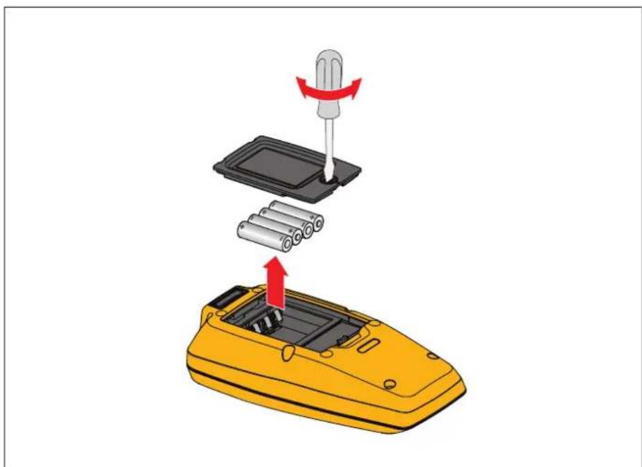
Figure 4 shows how to replace the batteries.
Figure 4. Battery Replacement
natural_image
Illustration of a yellow handheld device with battery pack and screwdriver being inserted into it (no text or symbols)Product Disposal
Dispose of the Product in a professional and environmentally sound manner:
- Delete personal data on the Product before disposal.
- Remove batteries that are not integrated into the electrical system before disposal and dispose of batteries separately.
- If this Product has an integral battery, put the entire Product in the electrical waste.
All Product names are trademarks of their respective companies. Specifications are subject to change without notice. Fluke Corporation. All rights reserved.


- EV Charging Station Analyzer
- LIMITED WARRANTY AND LIMITATION OF LIABILITY
- Table of Contents
- Title Page
- Introduction
- Contact Fluke
- Safety Information
- The Product
- Features
- Display
- Main Menu
- Menu Controls
- Note
- To change settings:
- Test Menu
- Set up a Test
- Project List Menu
- Create a Project
- To create a project:
- Add a Project
- To add a project:
- Delete a Project
- To delete a project:
- Enter Project Client and Site Codes
- To enter project client and site codes for a project:
- Project Menu
- Add a Station
- Copy a Station
- Edit a Station
- Delete a Station
- Configure a Station
- Caution
- Earth Bond Configuration (FEV350)
- Connect the Plug
- Connect the TPAK Strap
- Station and Connection Point Tests
- Warning
- Function Buttons in Tests
- Symbols on Test Screens
- Do a Test
- PE Pre-Test
- ⚠ Warning
- Visual Inspection Test
- How to do Tests
- For tests that use an MFT, connect the test leads to the MFT and then to the Product.
- Earth Bond Tests
- Insulation Input or Output Tests
- Loop/Line Impedance Test
- mA RCD Trip Test
- mA RDC-DD Trip Test
- Mains Voltage/Phase Sequence Test
- Nominal Voltage Test
- GFCI Trip Test
- Control Pilot Test
- Proximity Pilot Test
- Error Test
- Settings Menu
- Manual CP Menu
- Troubleshoot GFCI Menu
- TruTest™ Software Menu
- Maintenance
- Clean the Product
- Battery Replacement
- Product Disposal
Brand : FLUKE
Model : FEV150
Category : Meter