
PicoScope 3205D - Meter Pico - Free user manual and instructions
Find the device manual for free PicoScope 3205D Pico in PDF.


| Product Type | PC-based Digital Oscilloscope |
| Model | PicoScope 3205D |
| Bandwidth | 100 MHz |
| Analog Channels | 2 |
| Digital Channels | None (non-MSO model) |
| Maximum Sampling Rate | 1 GS/s |
| Buffer Memory | 256 MS |
| External Trigger | Yes (EXT input, BNC) |
| Arbitrary Waveform Generator | Yes (built-in, BNC output) |
| Input Voltage Range (Full Scale) | ±20 V |
| Overvoltage Protection | ±100 V |
| Connectivity | USB 3.0 SuperSpeed (also USB 2.0) |
| Power Supply | USB bus-powered, 5 V, 1.2 A |
| Probe Compensation | Required, compensation pin on front panel |
| Operating Temperature | 0 °C to +40 °C (+15 °C to +30 °C for accuracy) |
| Storage Temperature | -20 °C to +60 °C |
| Humidity (Operating) | 5% to 80% RH (non-condensing) |
| Software | PicoScope 6 (Windows); beta for Linux & macOS |
| Warranty | 5 years |
| Included Accessories | Quick Start Guide, Software CD, USB 3.0 cable, 2x 150 MHz probes (x1/x10) |
| Maintenance | Clean with soft cloth and mild soap solution; do not allow liquids inside |
| Safety Compliance | EN 61010-1:2010, double insulation, not for hazardous live signals |
| Repair | No user-serviceable parts; return to Pico Technology |
Frequently Asked Questions - PicoScope 3205D Pico
User questions about PicoScope 3205D Pico
0 question about this device. Answer the ones you know or ask your own.
Ask a new question about this device
Download the instructions for your Meter in PDF format for free! Find your manual PicoScope 3205D - Pico and take your electronic device back in hand. On this page are published all the documents necessary for the use of your device. PicoScope 3205D by Pico.
USER MANUAL PicoScope 3205D Pico
PicoScope® 3000 Series
D and D MSO model oscilloscopes
User's Guide
pico®
Technology
Contents
1 Introduction .... 1
1 Safety information .... 3
1 Symbols 4
2 Maximum input ranges .... 5
3 Grounding 6
4 External connections .... 6
5 Environment 7
6 Care of the instrument 7
2 Conformance 8
3 Software license conditions 9
4 Trademarks 9
5 Warranty 10
2 Product information 11
1 Connector diagrams ...... 11
1 2-channel model connector diagram ...... 12
2 4-channel model connector diagram ...... 13
3 2-channel MSO model connector diagram 14
4 4-channel MSO model connector diagram 15
5 Digital inputs on MSO models 16
2 Connectivity, power and installation 17
3 Minimum system requirements 19
4 Pack contents 20
5 Compensating probes 21
3 Glossary 22
Index 25
pico®
Technology
1 Introduction
Thank you for buying a PicoScope 3000D Series Oscilloscope from Pico Technology.
The PicoScope 3000D Series oscilloscopes are a range of high-specification real-time measuring instruments that connect to the USB port of your computer. With the PicoScope software you can use these devices as oscilloscopes, spectrum analyzers, and arbitrary waveform generators, plus as a logic analyzer on the mixed-signal models. The various model options offer portability, deep memory, two or four analog channels, mixed-signal inputs, fast sampling rates and high bandwidth, making these highly versatile oscilloscopes suitable for a wide range of applications.
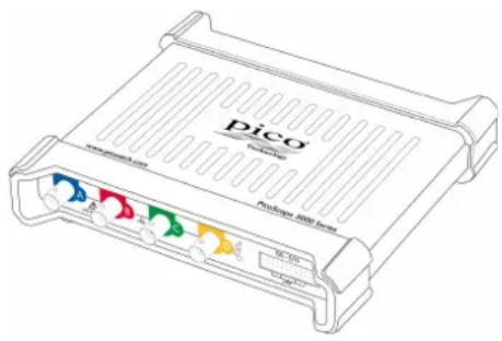
The PicoScope 3000D deep-memory oscilloscopes all feature a maximum sampling rate of 1 GS/s, USB 3.0 connectivity, and an arbitrary waveform generator, as well as the specifications below:
| Analog channels | Digital channels | External trigger | Bandwidth | Buffer memory | |
| 3203D | 2 | - | √ | 50 MHz | 64 MS |
| 3203D MSO | 16 | - | |||
| 3204D | 2 | - | √ | 70 MHz | 128 MS |
| 3204D MSO | 16 | - | |||
| 3205D | 2 | - | √ | 100 MHz | 256 MS |
| 3205D MSO | 16 | - | |||
| 3206D | 2 | - | √ | 200 MHz | 512 MS |
| 3206D MSO | 16 | - | |||
| 3403D | 4 | - | √ | 50 MHz | 64 MS |
| 3403D MSO | 16 | - | |||
| 3404D | 4 | - | √ | 70 MHz | 128 MS |
| 3404D MSO | 16 | - | |||
| 3405D | 4 | - | √ | 100 MHz | 256 MS |
| 3405D MSO | 16 | - | |||
| 3406D | 4 | - | √ | 200 MHz | 512 MS |
| 3406D MSO | 16 | - |
For full specifications, refer to the PicoScope 3000 Series Data Sheet on the Software and Reference CD or to the PicoScope 3000 Series section of www.picotech.com.
Some of the benefits provided by the PicoScope 3000D Series oscilloscopes are:
- Portability. Take the unit with you and simply plug it in to any Windows PC. (Linux and Mac OS X are also supported in the Beta software).
Performance. Up to 200 MHz bandwidth, 512 MS buffer, and a 1 GS/s sampling rate.
Mixed signal capability. Display analog and digital signals on the same timebase with the MSO models.
Flexibility. Use the device as an oscilloscope, spectrum analyzer, signal generator, or high-speed data acquisition interface.
Programmability. The PicoScope 3000A SDK lets you write your own programs, in your chosen programming language, to control all of the features of the scope. Using the API functions, you can develop your own programs to collect and analyze data from the oscilloscope. Refer to the PicoScope 3000 Series (A API) Programmer's Guide for more information.
Long-term support. Software upgrades are available to download from www.picotech.com. You can also call our technical specialists for support. These services are available free of charge for the lifetime of the product.
Value for money. You don't have to pay twice for features already available on your PC, as the PicoScope 3000 Series oscilloscope contains the specialized hardware you need and nothing more. - Convenience. The software makes full use of the display, disk storage, user interface, and networking built into your PC using a fast USB connection.
Five-year warranty. Your oscilloscope is covered against manufacturing faults for five years from the day of purchase. We don't charge a penny extra for this.
1.1 Safety information
To prevent possible electrical shock, fire, personal injury, or damage to the product, carefully read this safety information before attempting to install or use the product. In addition, follow all generally accepted safety practices and procedures for working with and near electricity.
The product has been designed and tested in accordance with the European standard publication EN 61010-1: 2010 and left the factory in a safe condition.
The following safety descriptions are found throughout this guide:
A WARNING identifies conditions or practices that could result in injury or death.
A CAUTION identifies conditions or practices that could result in damage to the product or equipment to which it is connected.
Each of these safety instructions applies to all of the PicoScope 3000 Series oscilloscopes covered by this User's Guide unless otherwise specified.
1.1.1 Symbols
These safety and electrical symbols may appear on the product and throughout this guide.
| Symbol | Description |
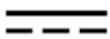 | Direct current |
 | Alternating current |
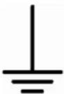 | Earth (ground) terminalThis terminal can be used to make a measurement ground connection. It is not a safety or protective earth. |
 | Chassis terminal |
 | Equipment protected throughout by double or reinforced insulation. |
 | Possibility of electric shock |
 | CautionAppearance on the product indicates a need to read these safety instructions. |
 | Do not dispose of this product as unsorted municipal waste. |

WARNING
To prevent injury or death, use the product only as instructed. Protection provided by the product may be impaired if used in a manner not specified by the manufacturer.
1.1.2 Maximum input ranges
Observe all terminal ratings and warnings marked on the product.
The table below indicates the full scale measurement range and overvoltage protection range for each oscilloscope model. The full scale measurement ranges are the maximum voltages that can be accurately measured by each instrument. The overvoltage protection ranges are the maximum voltages that can be applied without damaging the oscilloscope.

WARNING
To prevent electric shock, do not attempt to measure voltages outside the specified full scale measurement range below.
| Model | Full scale measurement range | Overvoltage protection | ||
| Input channels / EXT trigger | Signal generator | Digital channels (MSO models) | ||
| All PicoScope 3000D Series models | ±20 V | ±100 V | ±20 V | ±50 V |
WARNING
Signals exceeding the voltage limits in the table below are defined as "hazardous live" by EN 61010. To prevent electric shock, take all necessary safety precautions when working on equipment where hazardous live voltages may be present.
| Signal voltage limits of EN 61010 | ||
| ±70 V DC | 33 V AC RMS | ±46.7 V pk max. |
WARNING
PicoScope 3000D Series oscilloscopes are not designed to measure hazardous live signals as defined by EN 61010. To prevent electric shock, do not attempt to measure voltages outside of the limits shown in the table above or the specified full scale measurement range, whichever is lower.
WARNING
To prevent injury or death, the oscilloscope must not be directly connected to the mains (line power). To measure mains voltages, use a differential isolating probe specifically rated for mains use, such as the TA041 listed at www.picotech.com.

CAUTION
Exceeding the overload protection range on any connector can cause permanent damage to the oscilloscope and other connected equipment.
1.1.3 Grounding

WARNING
The oscilloscope's ground connection through the USB cable is for measurement purposes only. The oscilloscope does not have a protective safety ground.
WARNING
Never connect the ground input (chassis) to any electrical power source. To prevent personal injury or death, use a voltmeter to check that there is no significant AC or DC voltage between the oscilloscope ground and the point to which you intend to connect it.

CAUTION
Applying a voltage to the ground input is likely to cause permanent damage to the oscilloscope, the attached computer, and other equipment.
CAUTION
To prevent measurement errors caused by poor grounding, always use the high-quality USB cable supplied with the oscilloscope.
1.1.4 External connections

WARNING
To prevent injury or death, only use the power adaptor supplied with the product, where applicable. This is approved for the voltage and plug configuration in your country.
| PicoScope model | USB connection | Ext DC power input | |||
| USB 2.0* | USB 3.0 | Voltage (V) | Current (A pk) | Total power (W) | |
| 3203D | |||||
| 3204D | √ | √ | - | - | - |
| 3205D | |||||
| 3206D | |||||
| 3403D | |||||
| 3404D | √ | √ | 5 V | 1.2 A | 6.0 W |
| 3405D | |||||
| 3406D | |||||
| 3203D MSO | |||||
| 3204D MSO | √ | √ | - | - | - |
| 3205D MSO | |||||
| 3206D MSO | |||||
| 3403D MSO | |||||
| 3404D MSO | √ | √ | 5 V | 1.3 A | 6.5 W |
| 3405D MSO | |||||
| 3406D MSO | |||||
* Can be powered from a single USB 2.0 port, provided the port supplies the required power. The PicoScope software will notify you if the port is not suitable.
1.1.5 Environment

WARNING
To prevent injury or death, do not use in wet or damp conditions, or near explosive gas or vapor.

CAUTION
To prevent damage, always use and store your oscilloscope in appropriate environments. Recommended temperatures and humidity conditions are shown in the table below.
| PicoScope 3000D Series | ||
| Storage | Operating | |
| Temperature | -20 °C to +60 °C | 0 °C to +40 °C+15 °C to +30 °C(for quoted accuracy) |
| Humidity | 5% to 95% RH(non-condensing) | 5% to 80% RH(non-condensing) |
| Altitude | 2000 m | |
| Pollution degree | 2 | |
1.1.6 Care of the instrument
The oscilloscope and its accessories contain no user-serviceable parts. Repair, servicing, and calibration require specialized test equipment and must only be performed by Pico Technology or an approved service provider. There may be a charge for these services unless covered by the Pico five year warranty.

WARNING
To prevent injury or death, do not use the instrument if it appears to be damaged in any way, and stop use immediately if you are concerned by any abnormal operations.
WARNING
To prevent electric shock, do not tamper with or disassemble the oscilloscope, case parts, connectors, or accessories.
WARNING
When cleaning the oscilloscope, use a soft cloth and a solution of mild soap or detergent in water. To prevent electric shock, do not allow liquids to enter the casing, as this will cause damage to the electronics or insulation inside.

CAUTION
Do not tamper with or disassemble the oscilloscope, connectors or accessories. Internal damage will affect performance.
1.2 Conformance
1.2.1 FCC notice
This equipment has been tested and found to comply with the limits for a Class A digital device, pursuant to Part 15 of the FCC Rules. These limits are designed to provide reasonable protection against harmful interference when the equipment is operated in a commercial environment. This equipment generates, uses, and can radiate radio frequency energy and, if not installed and used in accordance with the instruction manual, may cause harmful interference to radio communications. Operation of this equipment in a residential area is likely to cause harmful interference in which case the user will be required to correct the interference at his or her own expense.
For safety and maintenance information see section 1.1.
1.2.2 CE notice
This product meets the intent of the EMC directive 2004/108/EC and has been tested to EN61326-1:2006 Class A Emissions and Basic Immunity.
The product also meets the intent of the Low Voltage Directive and has been designed to meet the BS EN 61010-1:2010 (safety requirements for electrical equipment for measurement, control, and laboratory use) standard.
1.3 Software license conditions
The software supplied with this product is licensed, not sold. Pico Technology Limited grants a license to the person who installs this software, subject to the conditions listed below:
Access. The licensee agrees to allow access to this software only to persons who have been informed of these conditions and agree to abide by them.
Usage. The software in this release is for use only with Pico Technology products or with data collected using Pico Technology products.
Copyright. Pico Technology Limited claims the copyright of, and retains the rights to, all material (software, documents etc.) contained in this release. You may copy and distribute the PicoScope and PicoLog software and drivers with no modifications, additions or omissions. You may copy and modify the SDK example programs.
Liability. Pico Technology and its agents shall not be liable for any loss, damage or injury, howsoever caused, related to the use of Pico Technology equipment or software, unless excluded by statute.
Fitness for purpose. Because no two applications are the same, Pico Technology cannot guarantee that its equipment or software is suitable for a given application. It is your responsibility, therefore, to ensure that the product is suitable for your application.
Mission-critical applications. This software is intended for use on a computer that may be running other software products. For this reason, one of the conditions of the license is that it excludes usage in mission-critical applications such as life-support systems.
Viruses. This software was continuously monitored for viruses during production, but you are responsible for virus-checking the software once it is installed.
Support. If you are dissatisfied with the performance of this software, please contact our technical support staff, who will try to fix the problem within a reasonable time. If you are still dissatisfied, please return the product and software to your supplier within 14 days of purchase for a full refund.
Upgrades. We provide upgrades, free of charge, from www.picotech.com. We reserve the right to charge for updates or replacements sent out on physical media.
1.4 Trademarks
Windows is a registered trademark or trademark of Microsoft Corporation, registered in the U.S. and other countries.
Linux is the registered trademark of Linus Torvalds, registered in the U.S. and other countries.
Mac and OS X are trademarks of Apple Inc., registered in the U.S. and other countries.
Pico Technology Limited and PicoScope are trademarks of Pico Technology Limited, registered in the United Kingdom and other countries.
PicoScope and Pico Technology are registered in the U.S. Patent and Trademark Office.
1.5 Warranty
Pico Technology warrants upon delivery, and for a period of 5 years unless otherwise stated from the date of delivery, that the Goods will be free from defects in material and workmanship.
Pico Technology shall not be liable for a breach of the warranty if the defect has been caused by fair wear and tear, wilful damage, negligence, abnormal working conditions or failure to follow Pico Technology's spoken or written advice on the storage, installation, commissioning, use or maintenance of the Goods or (if no advice has been given) good trade practice; or if the Customer alters or repairs such Goods without the written consent of Pico Technology.
2 Product information
2.1 Connector diagrams
Standard oscilloscope connectors
The analog input channels have standard BNC connectors and standard input impedances. They are therefore compatible with most oscilloscope probes including x10 and switched x1/x10 variants. For optimum performance, always use the probes supplied with your PicoScope.
Arbitrary waveform generator output
The built-in arbitrary waveform generator (AWG) can generate a waveform of almost any shape. The generated waveform can be injected into the device you wish to test and then analyzed as it progresses through the device to confirm correct operation, or to highlight a fault.
- If you are using the PicoScope 6 software, refer to the PicoScope 6 User's Guide for information on how to configure the arbitrary waveform generator.
- If you are writing your own software, refer to the PicoScope 3000 Series (A API) Programmer's Guide.
Digital inputs for mixed-signal oscilloscopes (D MSO models only)
Alongside the analog channels, the mixed-signal 3000D MSO Series oscilloscopes also feature 16 digital inputs. The PicoScope software allows you to view both digital and analog signals simultaneously. Your digital inputs are easily manageable, and can be reordered, grouped, and renamed.
Features such as triggering and serial decoding can also be used on the digital channels.
See Digital inputs for PicoScope 3000D Series MSO models for more information.
External trigger (EXT) input (D models only)
The EXT input can be used as a trigger source. Select it from the Trigger menu in the PicoScope software, or by using a function call if you are writing your own software.
The EXT input uses dedicated circuitry, in combination with a software-configurable threshold, to detect a trigger signal. This leaves the analog channels free for viewing signals. The input characteristics of the EXT input are matched to a scope channel so that the supplied, compensated probes can be used with the EXT input to give high vertical accuracy.
Where trigger timing accuracy is critical, we recommend using one of the main input channels as the trigger source. These channels use accurate digital triggering (to one sample period) and have a vertical resolution of 1 LSB.
USB port
All models have a SuperSpeed USB 3.0 port for connection to a PC. See Connectivity, power and installation for more information.
Earth terminal
External noise may sometimes interfere with your measurements if the PicoScope is used with a computer which does not have a ground connection. If this is the case, connect the earth terminal to an external ground point (for example, on the system you are testing) to provide a ground reference for the oscilloscope.
2.1.1
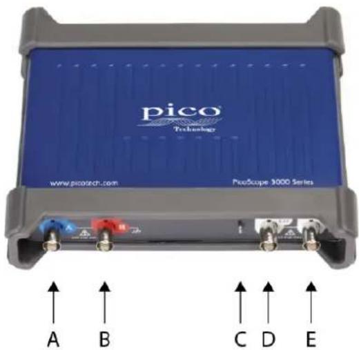
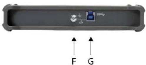
2-channel model connector diagram
PicoScope 3203D, 3204D, 3205D, and 3206D.
natural_image
Diagram of a device casing with internal components and directional arrows labeled F and G (no text or symbols on the main body)A. Input channel A
B. Input channel B
C. Probe compensation pin (above)
LED (below)
Flashes green when the oscilloscope is sampling data
D. External trigger (EXT) input
E. Arbitrary waveform generator output
F. Earth terminal
G. USB port
2.1.2
4-channel model connector diagram
PicoScope 3403D, 3404D, 3405D, and 3406D.
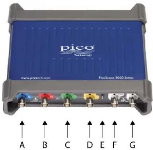
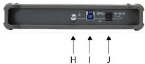
A. Input channel A
B. Input channel B
C. Input channel C
D. Input channel D
E. Probe compensation pin (above)
LED (below)
Flashes green when the oscilloscope is sampling data
F. External trigger (EXT) input
G. Arbitrary waveform generator output
H. Earth terminal
I. USB port
J. DC power input
2.1.3
2-channel MSO model connector diagram
PicoScope 3203D MSO, 3204D MSO, 3205D MSO, and 3206D MSO.
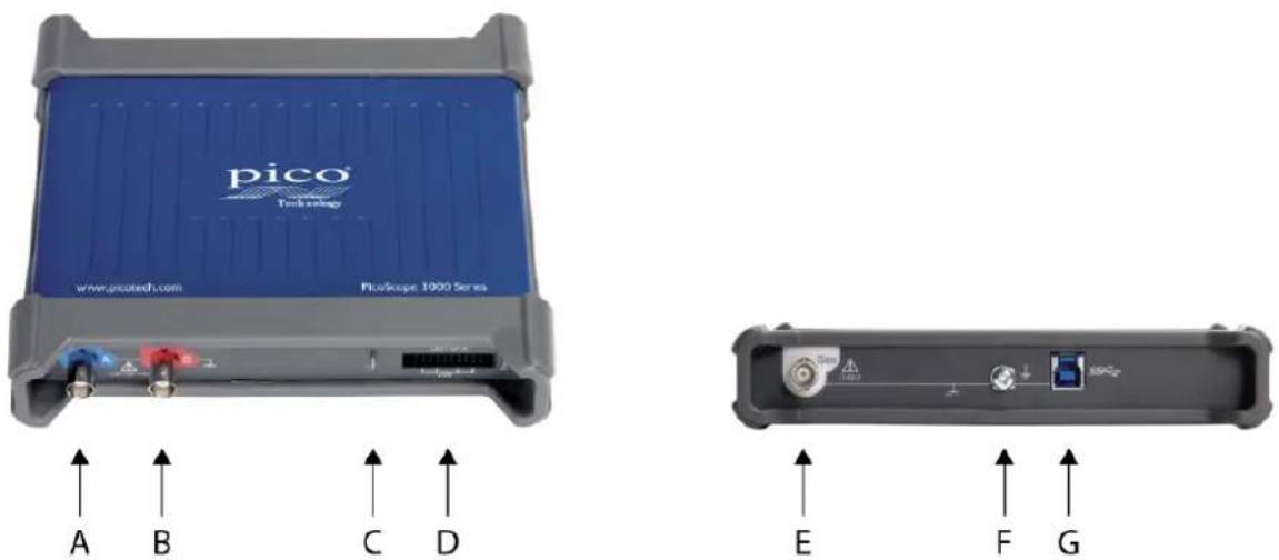
A. Input channel A
B. Input channel B
C. Probe compensation pin (above)
LED (below)
Flashes green when the oscilloscope is sampling data
D. Digital inputs D0 to D15
E. Arbitrary waveform generator output
F. Earth terminal
G. USB port
2.1.4
4-channel MSO model connector diagram
PicoScope 3403D MSO, 3404D MSO, 3405D MSO, and 3406D MSO.
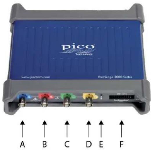
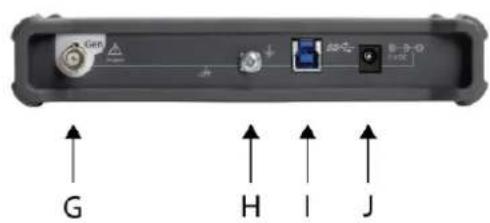
A. Input channel A
B. Input channel B
C. Input channel C
D. Input channel D
E. Probe compensation pin (above)
LED (below)
Flashes green when the oscilloscope is sampling data
F. Digital inputs D0 to D15
G. Arbitrary waveform generator output
H. Earth terminal
I. USB port
J. DC power input
2.1.5 Digital inputs on MSO models
The digital input pins of the 20-pin IDC header plug are shown below. The diagram is drawn as you look at the front panel of the oscilloscope.
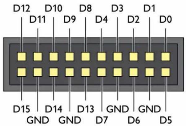
To avoid crosstalk on the digital inputs when probing signals with very fast edges, always take extra care to:
- Keep leads carrying fast signals separate from other input leads.
- Keep leads carrying fast signals as close as possible to the ground leads.
- Connect all four black ground leads to the ground of the circuit under test.
2.2 Connectivity, power and installation
1. PicoScope software installation
Before setting up your PicoScope 3000 Series oscilloscope, it is recommended that you first install the PicoScope 6 software by following the instructions in the supplied Quick Start Guide.
There are different connectivity and power supply options for each oscilloscope model depending on its specifications.
2. USB connectivity
For best results, use only the high-quality USB cables supplied with your PicoScope
- If your computer has a USB 3.0 port, connect the oscilloscope to it using the USB 3.0 cable supplied (image below).
- The oscilloscope is also compatible with a single USB 2.0 port, and can be connected using the USB 3.0 cable (image below), provided the port supplies the required power. The PicoScope software will notify you if the port is not suitable.
- If your computer does not have a USB 3.0 port or a suitable USB 2.0 port available, you can use a double-headed USB 2.0 cable (available separately) instead, which allows you to use a second USB port for additional power.
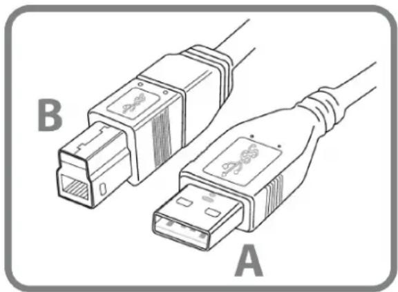
natural_image
Illustration of two USB connectors labeled A and B, showing internal wiring (no text or symbols beyond labels)Connector A: Connect to the USB port on your PC
Connector B: Connect to the USB port on your PicoScope 3000 Series oscilloscope
3. Oscilloscope installation
Once you have connected your oscilloscope to a PC using the appropriate USB cable, Windows will install the device. You will see different alerts depending on your operating system. There is no need to reinsert the software CD.
- Windows XP
A New Hardware Found wizard will be displayed. Simply click Next to run through the installation. If a Windows Logo Testing warning is displayed, click Continue Anyway.
- Windows Vista, Windows 7, Windows 8 and Windows 10
The process is automatic. An Installing device driver software message will be displayed during the installation.
Note: If you move your oscilloscope to a different USB port at any point the installation process will be repeated.
4. External power supply
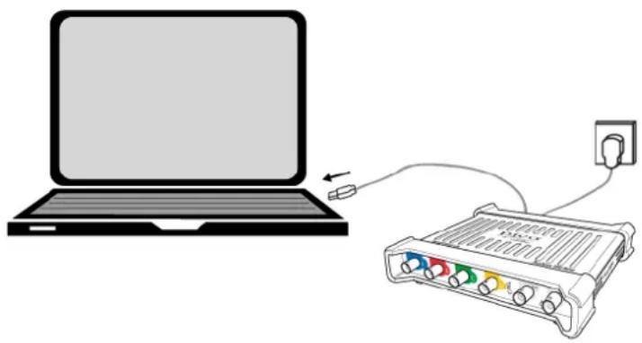
For PicoScopes with 4 analog channels, the supplied AC power adaptor may be required if the USB port(s) provide less than 1200 mA. The PicoScope software will notify you if the AC adaptor is required. Simply connect the adaptor and USB cable as shown below.
Note: if the AC adaptor is connected or disconnected while the oscilloscope is in operation, it will restart automatically and any unsaved data will be lost.
natural_image
Illustration of a laptop connected to an audio player with an attached power outlet (no text or symbols)5. Running the PicoScope software
Once you have connected the oscilloscope, start the PicoScope software. Signals connected to the scope inputs should now be displayed. If you touch a connected probe's tip with your finger, you should see a small 50 or 60 Hz signal in the oscilloscope window.
2.3 Minimum system requirements
To ensure that your PicoScope 3000 Series oscilloscope operates correctly, you must have a computer with the system requirements and one of the operating systems shown in the table below. The performance of the oscilloscope will be better with a more powerful PC, and will greatly benefit from a multi-core processor.
| Item | Specification |
| Operating system | Windows 7, Windows 8 (not Windows RT), Windows 10*.32 bit and 64 bit versions.Beta software is also available for Linux and OS X operating systems. |
| Processor | As required by the operating system |
| Memory | |
| Free disk space | |
| Ports | USB 3.0 or USB 2.0 port(s)** |
* PicoScope version 6.11 and SDKs are compatible with Windows XP SP3 and Vista SP2 in addition to the Windows versions listed above. For best performance we recommend Windows 7 or later.
** See Connectivity, power and installation for more information.
2.4 Pack contents
All PicoScope 3000 Series oscilloscope kits contain:
• PicoScope 3000 Series oscilloscope
- Quick Start Guide
- Software and reference CD
- USB 3.0 cable*
Each model is also supplied with probes and additional items as shown below.
| Probes (x1/ x10, 1.2 m) | Digital cable | Test clips | AC power adaptor | |
| 3203D | 60 MHz (x2) | - | - | - |
| 3203D MSO | √ | √ | ||
| 3204D | 150 MHz (x2) | - | - | |
| 3204D MSO | √ | √ | ||
| 3205D | 150 MHz (x2) | - | - | |
| 3205D MSO | √ | √ | ||
| 3206D | 250 MHz (x2) | - | - | |
| 3206D MSO | √ | √ | ||
| 3403D | 60 MHz (x4) | - | - | √ |
| 3403D MSO | √ | √ | ||
| 3404D | 150 MHz (x4) | - | - | |
| 3404D MSO | √ | √ | ||
| 3405D | 150 MHz (x4) | - | - | |
| 3405D MSO | √ | √ | ||
| 3406D | 250 MHz (x4) | - | - | |
| 3406D MSO | √ | √ |
* For more information on USB cables, see Connectivity, power and installation.
Each PicoScope 3000 Series oscilloscope is supplied with two or four probes that have been selected for use with that model. For optimal performance, always use the probes provided. Although other oscilloscope probes can be used, the specified performance cannot be guaranteed. Replacement probes can be ordered at www.picotech.com.
2.5 Compensating probes
We recommend that you compensate each oscilloscope probe before using it with your PicoScope, and repeat the procedure before using the probes for any precise measurement applications.
Specific compensation instructions and all required compensation accessories are supplied with each probe kit.
Connecting a probe for compensation
- Plug the probe's BNC connector into an input channel on the oscilloscope.
- Fit the spring hook on to the probe tip.
- Attach the spring hook to the probe compensation pin on the front panel of the oscilloscope.
- Attach the ground lead to the probe.
- Connect the crocodile clip to the ground shell of another input channel.
-
Run the PicoScope software.
-
Follow these steps using the PicoScope software:
a. Set the input coupling to DC.
b. Set the scope trigger to the channel you are compensating.
c. Click Auto Setup.
- Follow the compensation instructions supplied with the probe kit.
3 Glossary
API. Application Programming Interface. A set of function calls that give programmers access to the PicoScope 3000 Series (A API) driver.
AWG. Arbitrary waveform generator. A signal generator that can play back a waveform of any shape defined by the user.
Bandwidth. The range of input frequencies over which the measured signal amplitude is no more than 3 decibels below its true value.
Buffer size. The size of the oscilloscope buffer memory, measured in samples. In block mode, the buffer memory is used by the oscilloscope to store temporary data. This allows the oscilloscope to sample data independently of the speed at which it can transfer data to the computer.
Driver. A program that controls a piece of hardware. The driver for the PicoScope 3000 Series (A API) oscilloscopes is supplied in the form of a 32-bit or 64-bit Windows DLL, ps3000a.dll. This is used by the PicoScope software, and by user-designed applications, to control the oscilloscopes.
External trigger. The BNC connector marked EXT on the oscilloscope. It can be used as a trigger source but not as a waveform input.
GS/ s. Gigasamples (billions of samples) per second. Used to quantify the sampling rate of an oscilloscope.
Maximum sampling rate. A figure indicating the maximum number of samples the oscilloscope can acquire per second. Maximum sampling rates are usually given in MS/s (megasamples per second) or GS/s (gigasamples per second.) The higher the sampling rate of the oscilloscope, the more accurate the representation of the high-frequency details in a fast signal.
MS/ s. Megasamples (millions of samples) per second. Used to quantify the sampling rate of an oscilloscope.
MSO. Mixed-signal oscilloscope. An oscilloscope that has both analog and digital inputs.
PC oscilloscope. A virtual instrument formed by connecting a PicoScope oscilloscope to a computer running the PicoScope software.
PicoScope software. The software product that accompanies all Pico Technology oscilloscopes. It enables your PC to be an oscilloscope, spectrum analyzer, and meter display.
Signal generator. A built-in circuit that generates signals suitable for driving an external device under test. Its output is the BNC connector marked GEN or AWG on the oscilloscope. Connect a BNC cable between this output and one of the channel inputs to send a signal into the channel.
Timebase. A timer that controls the speed at which the scope captures data. At slow timebases this process is visible as PicoScope draws the trace across the scope view from left to right. At fast timebases PicoScope draws the whole trace in a single operation. The timebase is measured in units of time (such as seconds) per division. There are ten divisions across the scope view, so the total time across the width of the view is ten times the "per division" setting.
USB. Universal serial bus. A standard port that enables you to connect external devices to a computer.
USB 1.1. An early version of the USB standard, found on some older PCs. PicoScopes will operate slowly using a USB 1.1 port; performance will be greatly improved by using the recommended USB 2.0 or 3.0 port.
USB 2.0. A USB 2.0 port uses signaling speeds of up to 480 megabits per second and is backwards-compatible with USB 1.1.
USB 3.0. A USB 3.0 port uses signaling speeds of up to 5 gigabits per second and is backwards-compatible with USB 2.0 and USB 1.1.
Vertical resolution. A value, in bits, indicating the precision with which the oscilloscope converts input voltages to digital values. The resolution enhancement function can enhance the effective vertical resolution.
Voltage range. The range of input voltages that the oscilloscope can measure. For example, a voltage range of ±20 V means that the oscilloscope can measure voltages between -20 V and +20 V. Input voltages outside of this range will not be measured correctly. However they will not damage the instrument as long as they remain within the overvoltage protection range stated in the specifications.
pico®
Technology
Index
Power adaptor 6, 20
Probe compensation pin 13, 14, 15
Probes 20
compensating 21
A
Arbitrary waveform generator (Gen) 12, 13, 14, 15
R
Repair 7
C
CE notice 8
Cleaning 7
S
Safety symbols 4
Servicing 7
Software and reference CD 20
System requirements 19
D
DC power 13, 15
Digital inputs 14, 15, 16
T
Temperature 7
Trademarks 9
E
Earth terminal 12, 13, 14, 15
EXT connector 12, 13
External trigger 12, 13
U
USB cable 20
USB port 12, 13, 14, 15, 17, 19
USB power 17
F
FCC notice 8
W
Warranty 10
G
Gen output 12, 13, 14, 15
Grounding 6
H
Humidity 7
|
Input channels 12, 13, 14, 15
Input ranges 5
Installation guide 20
L
LED 12, 13, 14, 15
License conditions 9
M
Mixed-signal oscilloscope (MSO) 14, 15, 16
P
PicoScope software 18, 19
United Kingdom headquarters
Pico Technology
James House
Colmworth Business Park
St. Neots
Cambridgeshire
PE19 8YP
United Kingdom
Tel: +44 (0) 1480 396 395
Fax: +44 (0) 1480 396 296
sales@picotech.com
support@picotech.com
www.picotech.com
United States headquarters
Pico Technology
320 N Glenwood Blvd
Tyler
Texas 75702
United States
Tel: +1 800 591 2796
Fax: +1 620 272 0981
- PicoScope® 3000 Series
- D and D MSO model oscilloscopes
- Contents
- Introduction .... 1
- Safety information .... 3
- Conformance 8
- Software license conditions 9
- Trademarks 9
- Warranty 10
- Product information 11
- Connector diagrams ...... 11
- Connectivity, power and installation 17
- Minimum system requirements 19
- Pack contents 20
- Compensating probes 21
- Glossary 22
- Index 25
- Introduction
- Safety information
- Symbols
- WARNING
- Maximum input ranges
- CAUTION
- Grounding
- External connections
- Environment
- Care of the instrument
- Conformance
- FCC notice
- CE notice
- Software license conditions
- Trademarks
- Warranty
- Product information
- Connector diagrams
- Standard oscilloscope connectors
- Arbitrary waveform generator output
- Digital inputs for mixed-signal oscilloscopes (D MSO models only)
- External trigger (EXT) input (D models only)
- USB port
- Earth terminal
- 2.1.1
- 2.1.2
- 2.1.3
- 2.1.4
- Digital inputs on MSO models
- Connectivity, power and installation
- PicoScope software installation
- USB connectivity
- Oscilloscope installation
- - Windows XP
- - Windows Vista, Windows 7, Windows 8 and Windows 10
- External power supply
- Running the PicoScope software
- Minimum system requirements
- Pack contents
- Compensating probes
- Connecting a probe for compensation
- Glossary
- Index
- A
- R
- C
- S
- D
- T
- E
- U
- F
- W
- G
- H
- |
- L
- M
- P
Brand : Pico
Model : PicoScope 3205D
Category : Meter