
DPS5015 - Battery charger Joy-It - Free user manual and instructions
Find the device manual for free DPS5015 Joy-It in PDF.


| Product Type | Programmable Power Supply / Battery Charger |
| Input Voltage | 6V - 60V DC |
| Output Voltage | 0 - 50V (adjustable in 10mV steps) |
| Output Current | 0 - 15A (adjustable in 1mA steps) |
| Output Power | 0 - 750W |
| Voltage Accuracy | ± 0.5% |
| Current Accuracy | ± 0.5% |
| Display | 1.44" Color LCD |
| Display Module Dimensions | 80 x 42 x 45 mm |
| Power Module Dimensions | 40 x 67 x 91 mm |
| Weight | 152g |
| Protection Features | Over-Voltage Protection (OVP), Over-Current Protection (OCP), Over-Power Protection (OPP) |
| Data Groups | 10 programmable memory groups (M0 - M9) |
| Special Functions | Keyboard lock, auto-restore last settings, quick selection of M1/M2 |
| Connections | Screw terminals for input (IN+, IN-) and output (OUT+, OUT-); LCD and key interface via included cables |
Frequently Asked Questions - DPS5015 Joy-It
User questions about DPS5015 Joy-It
0 question about this device. Answer the ones you know or ask your own.
Ask a new question about this device
Download the instructions for your Battery charger in PDF format for free! Find your manual DPS5015 - Joy-It and take your electronic device back in hand. On this page are published all the documents necessary for the use of your device. DPS5015 by Joy-It.
USER MANUAL DPS5015 Joy-It
natural_image
Electronic components including a black DETER controller, flexible fiber optic cables, and a green circuit board with capacitors and inductors (no visible text or symbols)DPS5015
Programmable power supply unit
TABLE OF CONTENTS
- Introduction
- General informations
- Technical specifications
- Connection details
- Panel and display
- Use of the device
6.3 Configuration of data groups
6.4 Data group quick selection
6.6 keyboard lock - Other informations
- Support
6.1 Output voltage and current limitation
6.2 Setting the data and protection values
6.5 Activating and deactivating the output
1. INTRODUCTION
Dear customer,
thank you very much for choosing our product. In the following we have listed what you have to consider during commissioning.
2. GENERAL INFORMATIONS
This power supply combines analog and digital technologies in an advanced design, offering outstanding precision and accuracy. The adjustable output reaches up to 50V or 15A and can be precisely configured in 10mV or 1mA steps.
The power supply is additionally equipped with a switch-off parameter memory and ten programmable data memories. The operation of the device has been optimised for particularly simple operation and the colour display offers a particularly detailed and comprehensive display of information. Among other things, the current voltage and current values, presettings and output powers can be displayed here. Dynamic notification symbols also facilitate clarity.
The additional settings menu offers maximum control of overcurrent and overvoltage values as well as other parameters. The DPS5015 offers modern design and advanced technology in a compact package, making it the ideal power supply.
3. TECHNICAL SPECIFICATIONS
| Input voltage | 6V - 60V |
| Output voltage | 0 - 50V |
| Output current | 0 - 15A |
| Output power | 0 - 750W |
| Weight 152g | |
| Display size 1,44" | |
| Display Module Size 80 x 42 x 45 mm | |
| Power Module Size 40 x 67 x 91 mm | |
| Accuracy of the output voltage | ± 0,5% |
| Accuracy of the output current | ± 0,5% |
3. CONNECTION DETAILS
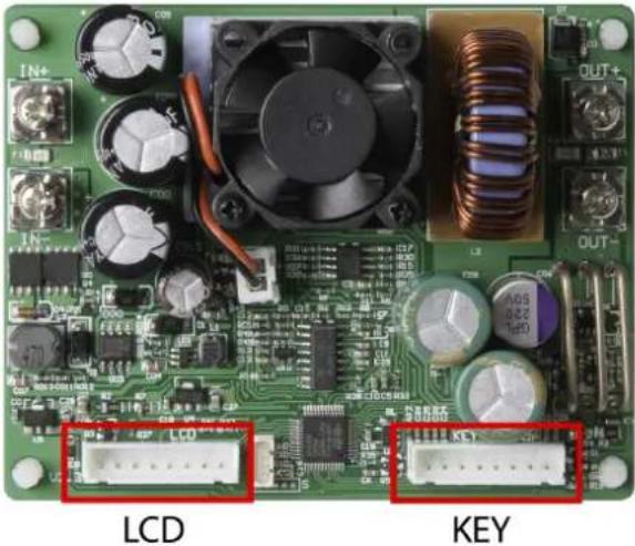
natural_image
Close-up of a green printed circuit board with labeled components including LCD, power supply, and key (no readable text beyond labels)First connect the display module with the enclosed cables to the corresponding LCD and key interface. In the next step, you can connect the inputs and outputs to the device via the screw terminals.
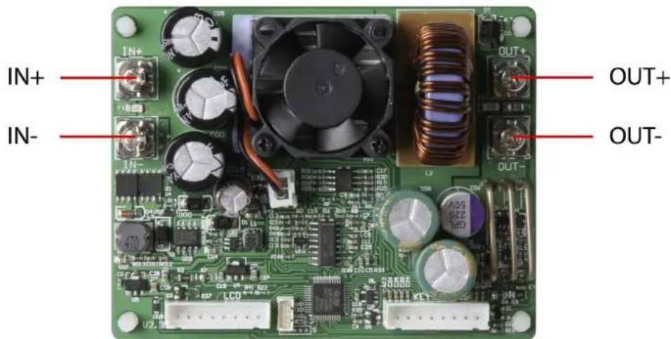
| IN+ Positive Input | |
| IN- Negative Input | |
| OUT+ Positive Output | |
| OUT- Negative Output |

Attention! Make sure that the input voltage is always Ensure that the input voltage is always at least 1.1 times the

The permissible input voltage range is 6 - 60V (DC). Always ensure a sufficient safety distance and never exceed the maximum permissible input voltage. Non-observance can lead to considerable damage to the device.

Operate the device exclusively with direct current! Operating the device with alternating current can lead to fatal electric shocks and irreparable damage to the device.
4. PANEL AND DISPLAY
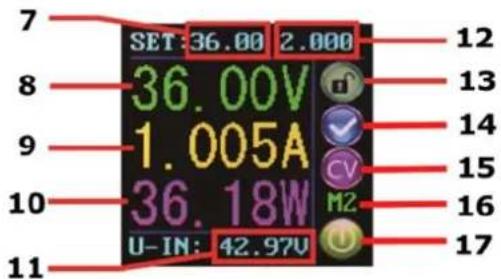
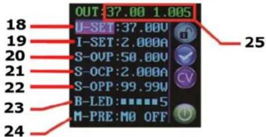
After the first start, the welcome screen is displayed followed by the main screen. Selected voltage and current limits are displayed on the main screen. When the output is active, the current actual values are also displayed. On the right side of the screen there are icons and prompts that indicate the system status. For a detailed description of the display, refer to the following illustrations:
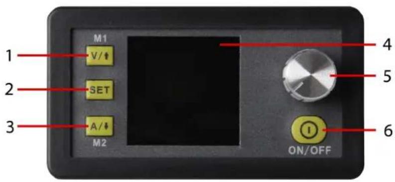
| 1 Voltage setting / up arrow / M1 Data group | |
| 2 | Data input / Extract data from a data group / Save value to selected data group |
| 3 Limit value settings / Down arrow / M2 Data group | |
| 4 | 1,44“ LCD-Display |
| 5 Rotary switch / key lock | |
| 6 Output Activate/deactivate | |
The main interface
Data setting interface
| 7 Output voltage (default) | |
| 8 Output voltage (current value) | |
| 9 Output current (current value) | |
| 10 Output power (current value) | |
| 11 Rotary switch / key lock | |
| 12 Output current Limit | |
| 13 Lock/unlock keyboard | |
| 14 Normal/Anormal Status | |
| 15 Constant voltage/constant current | |
| 16 data group number | |
| 17 Output active/inactive | |
| 18 Preset output voltage | |
| 19 Preset output current limitation | |
| 20 Preset overvoltage limit | |
| 21 | Preset overcurrent limit |
| 22 | Preset overload limit |
| 23 | Preset screen brightness |
| 24 | Preset data group number |
| 25 | Actual value of output voltage and output current |
6. USE OF THE DEVICE
6.1 OUTPUT VOLTAGE AND CURRENT LIMITATION
Press V/↑ to enter the voltage setting mode. Press the Rotary encoder to move the cursor to the numeric value you want to change. Turning the knob clockwise increases the value and counterclockwise decreases the value. Press V/↑ erneut to exit. Alternatively, after 30 seconds of inactivity, the setting mode will automatically exit. Press A/↓ um to set the output current limit in the same way.
6.2 SETTING THE DATA AND PROTECTION VALUES
In the main menu, press the SET button to open the data setting menu.
SET VOLTAGE AND CURRENT LIMITS
Navigate through the menu to go to the U-SET (voltage) or I-SET (voltage limit) option. Set the output voltage and/or the output current limit here according to your needs. You can then use the SET button to return to the menu options. Press the SET button again to exit the menu.
SETTING THE PROTECTION VALUES
Navigate through the menu to access the limit value options Option S-OVP (Over-Voltage-Protection), S-OCP (Over-Current-Protection) or S-OPP (Over-Power-Protection). Use the Rotary encoder to set the desired value. Press the SET button to return to the menu options and press the SET button again to exit the menu. The output is automatically deactivated when one of the protection value limits is reached.

Attention! These are the global system protection limits! These are the global system protection limits and should not be confused with preset voltages and currents.
Navigate to the B-LED option to configure the display brightness. Turn the Rotary encoder to adjust the brightness from 0 to 5.0 defines the darkest setting and 5 the brightest setting. Press the SET button to return to the menu options and press the SET button again to exit the menu.
6.3 CONFIGURATION OF DATA GROUPS
DATA GROUP M0
The M0 data group is a special case. It is the standard data group. Each time an alternative data group is selected or changes are made to the existing settings, M0 is immediately overwritten with the newly selected data.
M0 is therefore a real-time duplicate of the currently selected data group and data values. It is also the data set that is stored when the device is switched off and recalled the next time it is switched on. This is done automatically and transparently without user input.
SELECTION OF THE DATA GROUP TO BE PROCESSED
Navigate to the M-PRE option to edit a data group. Turn the Rotary encoder to select the number of the data group you want to view and edit. When the desired setting is complete, press and hold the SET button until the data group number is displayed on the right side of the screen. Press the SET button again to return to the data group settings.
ACTIVATION/DEACTIVATION
Navigate to the M-PRE option, and then press the Rotary encoder. Turn the Rotary encoder to select the number of the data group you want to view and edit, and press the Rotary encoder again to change the M-PRE option.
When this option is enabled, the output state remains unchanged when a data group is accessed. If you deactivate this option, the output is automatically switched off when you call up a data group.
Press and hold the SET key until the data group number is displayed on the right side of the screen. The data value is now stored under the specified data group number. Press the Set button again to return to the Data Group menu items. To exit the Data Group menu, press the Set key again.
6.4 DATA GROUP QUICK SELECTION
KEY COMBINATION FOR SELECTION OF M1/M2
Press and hold V/↑ or A/↓ for more than 3 seconds to quickly access the M1 or M2 data group. The corresponding data group number is displayed on the right side of the screen. Data groups M1 and M2 are ideal for frequently used settings due to the DeepL access function.
SELECTION OF ANY DATA GROUP
Press and hold the SET button for more than 3 seconds, M0 will be displayed on the right side of the screen. Turn the Rotary encoder to select the desired data group (M1 through M9). To activate the selected data group, press the SET button.
PROCESSING OF THE SELECTED DATA GROUP
To edit the selected data group, first use V/↑ or A/↓ to navigate up or down through the menu options. Then press the knob and the corresponding numeric value will be highlighted by the cursor. Additional knob operations scroll through the available characters. After setting the desired value, press and hold the SET button until the data group number is displayed on the right side of the screen. The data value is now stored under the specified data group number. Press the Set button again to return to the previous menu. Repeat the above procedure to change one of the other numeric values for the selected data group. To exit the menu, press the Set button again.
STATUS OF THE SELECTED DATA GROUP WHEN SWITCHING ON
You can configure the device to automatically activate the output when the device is turned on. To do this, navigate to the S-INI option and set the value to ON to activate the option. After selecting the desired setting, press and hold the SET button until the data group number is displayed on the right side of the screen. The data value is now stored. Press the Set button again to return to the previous menu. To exit the menu, press the Set button again.
6.5 ACTIVATING AND DEACTIVATING THE OUTPUT
You can press the ON/OFF button at any time to activate or deactivate the output.
6.6 KEYBOARD LOCK
Keyboard operation can be disabled to prevent accidental operation and unwanted changes. You can simply hold down the knob for more than 3 seconds at any time to lock or unlock all keys. The lock status is indicated by the lock icon on the right side of the screen.
7. OTHER INFORMATIONS
Our information and take-back obligations according to the Electrical and Electronic Equipment Act (ElektroG)
Symbol on electrical and electronic equipment:

This crossed-out dustbin means that electrical and electronic equipment does not belong in the household waste. You must return the old appliances to a collection point.
Before handing over waste batteries and accumulators that are not enclosed by waste equipment must be separated from it.
Return options:
As an end user, you can return your old appliance (which essentially fulfils the same function as the new appliance purchased from us) free of charge for disposal when you purchase a new appliance.
Small appliances with no external dimensions greater than 25 cm can be disposed of in normal household quantities independently of the purchase of a new appliance.
Possibility of return at our company location during opening hours:
Simac GmbH, Pascalstr. 8, D-47506 Neukirchen-Vluyn
Possibility of return in your area:
We will send you a parcel stamp with which you can return the device to us free of charge. Please contact us by e-mail at Service@joy-it.net or by telephone.
Information on packaging:
If you do not have suitable packaging material or do not wish to use your own, please contact us and we will send you suitable packaging.

8. SUPPORT
We also support you after your purchase. If there are any questions left or if you encounter any problems, please feel free to contact us by mail, phone or by our ticket-system on our website.
E-Mail: service@joy-it.net
Ticket-System: http://support.joy-it.net
Phone: +49 (0)2845 98469 - 66 (9:30 - 17:00 o'clock)
For further information please visit our website:
www.joy-it.net
- DPS5015
- TABLE OF CONTENTS
- INTRODUCTION
- GENERAL INFORMATIONS
- TECHNICAL SPECIFICATIONS
- CONNECTION DETAILS
- PANEL AND DISPLAY
- USE OF THE DEVICE
- OUTPUT VOLTAGE AND CURRENT LIMITATION
- SETTING THE DATA AND PROTECTION VALUES
- SET VOLTAGE AND CURRENT LIMITS
- SETTING THE PROTECTION VALUES
- CONFIGURATION OF DATA GROUPS
- DATA GROUP M0
- SELECTION OF THE DATA GROUP TO BE PROCESSED
- ACTIVATION/DEACTIVATION
- DATA GROUP QUICK SELECTION
- SELECTION OF ANY DATA GROUP
- PROCESSING OF THE SELECTED DATA GROUP
- STATUS OF THE SELECTED DATA GROUP WHEN SWITCHING ON
- ACTIVATING AND DEACTIVATING THE OUTPUT
- KEYBOARD LOCK
- OTHER INFORMATIONS
- Return options:
- Possibility of return in your area:
- Information on packaging:
- SUPPORT
Brand : Joy-It
Model : DPS5015
Category : Battery charger