
Alpha - Drone Autel - Free user manual and instructions
Find the device manual for free Alpha Autel in PDF.


| Product Type | Quadcopter Drone |
| Brand | Autel |
| Model | Alpha |
| Dimensions (folded) | 210 x 120 x 90 mm |
| Weight (with battery) | 800 g |
| Max Flight Time | 30 minutes |
| Max Transmission Range | 7 km |
| Camera Resolution | 4K @ 60fps |
| Gimbal | 3-axis stabilized |
| Battery Type | LiPo 4S 4500 mAh |
| Charging Time | Approx. 90 minutes |
| Max Ascent Speed | 5 m/s |
| Max Descent Speed | 3 m/s |
| Max Wind Resistance | Level 5 (8-10 m/s) |
| Operating Temperature | 0°C to 40°C |
| Storage Temperature | -10°C to 60°C |
| GPS | GPS + GLONASS |
| Obstacle Avoidance | Forward & Downward |
| Max Payload | Not applicable (integrated camera) |
| Maintenance | Clean optics with soft cloth; update firmware regularly |
| Safety Features | Return to Home, Low battery warning, Geofencing |
| Spare Parts Available | Propellers, batteries, landing gear |
Frequently Asked Questions - Alpha Autel
User questions about Alpha Autel
0 question about this device. Answer the ones you know or ask your own.
Ask a new question about this device
Download the instructions for your Drone in PDF format for free! Find your manual Alpha - Autel and take your electronic device back in hand. On this page are published all the documents necessary for the use of your device. Alpha by Autel.
USER MANUAL Alpha Autel
natural_image
Line drawing of a quadcopter drone with four propellers and control panels (no text or symbols)Copyright
This manual is copyrighted by Autel Robotics Co., Ltd. with all rights reserved. Without prior written authorization from the company, no person (or entity) may copy, scan, store, distribute, reproduce, sell, transfer, or modify any part or all of this manual in any form for personal use or use by others. Users should only refer to this manual and the content thereof as instructions to operate this product. This manual should not be used for other purposes.
Trademark Information
Autel Alpha ^™ , Autel Enterprise ^™ and AUTEL ^® trademarks are registered trademarks of the Autel Robotics Co., Ltd. (hereinafter referred to as "Autel Robotics") in China or other countries/regions.
Reading Assistance
- This manual is an electronic PDF document that supports high-resolution printing.
- If you are using a PDF reader such as Adobe Reader or Microsoft Edge to read this manual, press Ctrl+F on Windows or Command+F on Mac to search for keywords.
- View the content structure in the table of contents and click on titles to navigate to the respective pages.
Thank you for purchasing and using the Autel Alpha aircraft (hereinafter referred to as "aircraft") from Autel Robotics. Relevant user documents for this product are provided in electronic and print form along with the product, and download links are provided in this manual. Before using this product, please carefully read the operation steps and precautions in this manual, so that you can quickly understand the characteristics and usage methods of this product, so as to ensure safe use of the product.
| ● The final interpretation right of this document and all related documents of this product belongs to Autel Robotics.● This document is subject to update without notice. |
Legend
The following symbols are used in this manual to draw the user's attention to important safety and operating information. Please be sure to follow the notes or requirements under each symbol, otherwise, it may affect the safety features of the product or cause personal injury.
| Symbol | Definition |
 | Warning: Alerts to a potentially hazardous situation. |
 | Important: Reminds the user to pay attention to a point. |
 | Remarks: Supplementary information. |
 | Tips: Quick tips to get the best possible experience. |
Read Before Your First Flight
To ensure safe use of the Autel Alpha aircraft, Autel Robotics provides you with the following documents and relevant tutorial videos. Please scan the QR codes in this manual or use the provided links to access them.
- "Packing List": A list of everything that should be included in the packing box.
- "Disclaimer and Safety Operation Guidelines": Instructions on how to operate the product safely.
- "Battery Safety Operation Guidelines": Basic knowledge and safe handling of smart batteries.
- "Quick Start Guide": Basic knowledge of operating the product.
- "User Manual": A guide for you to master the operation method of the product proficiently.
- "Maintenance Manual": Instructions on how to maintain the aircraft and its accessories.
We recommend that you first check the completeness of the items in the packing box according to the "Packing List", then read the "Disclaimer and Safety Operation Guidelines" carefully, and then watch the tutorial videos and read the "Quick Start Guide" to get a basic understanding of how to use the product.
Before your first flight, please read the "Battery Safety Operation Guidelines" and "User Manual" carefully to get a more detailed understanding of how to use the product.
Getting Tutorial videos, User Documents, and Relevant Software
You can scan the QR codes below or visit the following links to access tutorial videos and user documents or download relevant software for the Autel Alpha aircraft:
To watch tutorial videos, please visit:
https://www.autelrobotics.com/videos/autel-alpha/.

To download resources, please visit:
https://manuals.autelrobotics.com/?dir=/Autel%20Alpha/Aircraft/.

Manual Guide
This manual contains 7 main chapters and 3 appendices. You can refer to the corresponding chapters for the desired information.
| Chapter Chapter Overview | |
| Product Overview | This chapter introduces the main functions of the Autel Alpha aircraft. |
| Flight Safety | This chapter introduces the flight environment, wireless communication requirements, and important flight safety features of the aircraft. |
| Aircraft | This chapter introduces the functions and usage of various components of the Autel Alpha aircraft. |
| Remote Controller | This chapter introduces the functions of the Autel Smart Controller V3, including how to use the controller to operate the aircraft. |
| Smart Battery | This chapter introduces how to use, store, and maintain the smart battery of the aircraft. |
| Autel Enterprise App | This chapter introduces the interfaces and functions of the Autel Enterprise App. |
| Firmware Updates and Maintenance | This chapter introduces how to perform firmware updates and routine maintenance for the aircraft. |
| Appendix A | This chapter provides technical specifications for the Autel Alpha aircraft and its accessories. |
| Appendix B | EU Declaration of Conformity for Autel Alpha Aircraft. |
| Appendix C | EU Drones Pilot Information Notices. |
Disclaimer
To ensure the safe and successful operation of this product, please read and fully understand all user documents listed above and strictly follow the operating instructions and steps described in this manual. Store the aircraft and its accessories out of the reach of children and pets. If you do not abide by the Safety Operation Guidelines, Autel Robotics shall not be responsible for any product damage or personal and property loss during use, and shall not provide any warranty service. Never modify the product using any incompatible component or in any way that does not conform to the official instructions of Autel Robotics. Please make sure that the operations you perform do not endanger the personal or property safety of yourself or those around you. By starting to use this product, you agree that you have read and accepted all terms related to this product. You undertake to be responsible for your own actions and all consequences arising therefrom. You undertake to use this product only for legitimate purposes and agree to these terms and any relevant policies or guidelines that Autel Robotics may establish.

Important
- When unboxing the product for the first time, carefully check the aircraft and other accessories included in the packing box according to the "Packing List".
- The content of this manual will be updated from time to time based on the function updates of the product.
- Please be aware that in the absence of flight logs from the Autel Enterprise App, Autel Robotics may not be able to analyze the causes of product damage or accidents and provide after-sales service.

Warning
- Using the Autel Alpha aircraft of Autel Robotics involves certain safety risks. Do not allow minors to operate the aircraft.
- The operation of this aircraft requires obtaining flight certifications in accordance with the relevant local laws and registrations of the country or region where it is being operated.
● The equipment and its accessories may only be operated and serviced by Skilled users. - This equipment is not suitable for operational use in locations where children are likely to be present.
Warranty Policy
Autel Robotics guarantees users who purchase products through its official authorized channels that:
- Under normal use, the Autel Robotics products you purchase will be free from material and workmanship defects during the warranty period.
- If you can provide a valid purchase receipt, the warranty period of this product is calculated from the midnight of the next day after you receive the product.
- If you cannot provide a valid purchase receipt, the warranty start date will be postponed by 90 days from the date of manufacture indicated by the product's serial number or as defined by Autel Robotics.
| Tip |
| ● For the after-sales policy of the product, please visit:https://www.autelrobotics.com/service/policy/. |
After-Sales Support
If you have any questions or concerns about our products, please contact Autel Robotics customer support:
Hotline: (844) MY AUTEL or (844) 692-88 35
Maintenance Service
If your equipment needs to be inspected or repaired, please contact Autel Robotics through the following methods:
- Email after-sale@autelrobotics.com or support@autelrobotics.com.
- Call Autel Robotics customer support at (844) MY AUTEL or (844) 692-88 35.
- Contact dealers authorized by Autel Robotics.
| Important |
| ● All data stored on the product may be erased during the repair process. To avoid data loss, please back up important files in your aircraft or remote controller before the product is under warranty. |
Company Information
Manufacturer:
Autel Robotics Co., Ltd.
Address:
601,701,801,901, Block B1, Nanshan iPark, No. 1001 Xueyuan Avenue, Nanshan District, Shenzhen, Guangdong, 518055, China
Official Website:
www.autelrobotics.com.
Table of Contents
Chapter 1 Product Overview....1
1.1 Introduction....1
1.2 What's In The Rugged Case.... 2
1.3 Product Acceptance Checklist 3
1.4 UAS Introduction....5
Chapter 2 Flight Safety 8
2.1 Legal Use Notice....8
2.1.1 Chinese Mainland 8
2.1.2 The U.S. 9
2.1.3 The EU 9
2.1.4 Other Countries and Regions 10
2.2 Flight Operation Guidelines....10
2.3 Flight Environment Requirements....10
2.4 Wireless Communication Requirements....11
2.5 Declaration of Maximum Take-off Mass....11
2.6 Obstacle Avoidance System....12
2.6.1 Introduction to Visual Sensing System and Millimeter-Wave Radar Sensing System 12
2.6.2 Observation Range....13
2.6.3 Visual Positioning Function 15
2.6.4 Visual Obstacle Avoidance Function....16
2.6.5 Precautions for Using Obstacle Avoidance Systems 16
2.7 Auto-return 17
2.7.1 Manual Auto-return Activation.... 17
2.7.2 Low Battery Auto-return Activation....17
2.7.3 Behavior-based Auto-return Activation 18
2.7.4 Auto-return Mechanism 19
2.7.5 Auto-return Obstacle Avoidance Process 19
2.7.6 Landing Protection Function 20
2.8 Rebuilding the C2 Link....20
2.9 Flight Restrictions and Unlocking Restricted Zones 21
2.9.1 Geofencing System 21
2.9.2 Restricted Zones 22
2.9.3 UGZ Import....24
2.9.4 Unlocking No-Fly Zones 25
2.10 Altitude and Distance Limits 25
2.11 Aircraft Calibration....26
2.11.1 Compass Calibration....26
2.11.2 IMU Calibration....28
2.11.3 Gimbal Calibration 30
2.12 Emergency Stop Propellers During Flight....31
2.13 Mid-flight Sensing 32
2.14 Direct Remote Identification 32
2.15 Standard Flight Operation Process 33
2.15.1 Pre-Flight Checklist....33
2.15.2 Basic Flight Process....34
2.16 List of Safeguard 34
Chapter 3 Aircraft 35
3.1 Aircraft Activation....35
3.2 Aircraft Components 35
3.3 Preparation Of Aircraft....40
3.3.1 Replacing Propellers 40
3.3.2 Fold/Unfold The Arms....42
3.4 Arm Light 43
3.5 Strobe 45
3.6 Auxiliary Bottom Light 46
3.7 Camera 47
3.7.1 Camera Structure 47
3.7.2 Camera Operations....48
3.7.3 Gimbal Structure 49
3.7.4 Gimbal Mechanical Rotation Range....50
3.7.5 Gimbal Operations....50
3.7.6 Replacing The Gimbal 51
3.7.7 Other Functions....53
3.8 Flight Control System....53
3.8.1 Flight Status....53
3.8.2 Flight Modes....54
3.8.3 Intelligent Flight Function....55
3.8.4 Hot Swap Battery....55
3.9 Installing the microSD Card 56
3.10 Connecting to PC/MAC 56
3.11 Extension Interface....57
3.12 Protection Rating 58
3.13 Noise....58
3.14 Autel SkyLink Image Transmission Function....59
Chapter 4 Remote Controller....63
4.1 Introduction 63
4.1.1 Remote Controller Components 63
4.1.2 Communication Frequency Bands....66
4.2 Installing the Remote Controller Lanyard 69
4.3 Installing/Storing Command Sticks....69
4.4 Turning the Remote Controller On/Off 70
4.5 Checking the Battery Level of the Remote Controller 71
4.6 Charging the Remote Controller....73
4.7 Adjusting the Antenna Position of the Remote Controller 73
4.8 Remote Controller System Interfaces 74
4.8.1 Remote Controller Main Interface 74
4.8.2 Shortcut Menu 77
4.9 Frequency Pairing With the Remote Controller 78
4.9.1 Using the Autel Enterprise App 78
4.9.2 Using Combination Keys (For Forced Frequency Pairing) 79
4.10 Selecting Stick Mode....80
4.10.1 Stick Modes 80
4.10.2 Setting Stick Mode....82
4.10.3 Starting/Stopping the Aircraft Motor 84
4.11 Remote Controller Keys 84
4.11.1 Custom Keys C1 and C2 84
4.11.2 Take-off/Return-to-Home Button and Pause Button 86
4.12 Turning On/Off the Remote Controller Prompt Sound 87
4.13 Calibrating the Remote Controller 87
4.14 HDMI Screen Output 88
Chapter 5 Smart Battery....89
5.1 Battery Introduction 89
5.2 Smart Battery Functions 90
5.3 Smart Battery Usage....91
5.3.1 Installing/Removing the Smart Battery 92
5.3.2 Checking Battery Level 93
5.3.3 Smart Battery Self-heating....94
5.3.4 Charging the Smart Battery 96
5.4 Storing and Transporting the Smart Battery....97
5.5 Maintaining and Handling the Smart Battery 98
5.5.1 Maintaining the Smart Battery 98
5.5.2 Standard Charging and Discharging Process 99
5.5.3 Smart Battery Replacement Standards....99
5.5.4 Recycling the Smart Battery....99
Chapter 6 Autel Enterprise App....100
6.1 Software Introduction .... 100
6.2 Main Interface....100
6.3 Status Notification Bar 102
6.4 Shortcut Toolbar 103
6.5 "Settings" Interface....106
6.5.1 Flight Control Parameter Setting....107
6.5.2 OA Settings....109
6.5.3 RC Settings....111
6.5.4 Image Transmission Settings....112
6.5.5 Aircraft Battery 113
6.5.6 Gimbal Settings....115
6.5.7 RTK Settings 116
6.5.8 More....117
6.6 Attitude Ball 120
6.7"Map" Interface 121
6.8 Camera Interfaces....124
6.8.1 Camera Function Area....124
6.8.2 "Zoom Camera" Interface....127
6.8.3 "Thermal Camera" Interface 128
6.8.4 "Wide Angle Camera" Interface 130
6.9 Flight Missions 131
6.9.1 Waypoint....132
6.9.2 Rectangle Mission 138
6.9.3 Polygon 144
6.9.4 Pre-flight Check....147
6.9.5 Resume Mission 148
6.9.6 Mission and Favorites....149
6.9.7 Personal Center 150
Chapter 7 Firmware Updates and Maintenance....151
7.1 Aircraft and Remote Controller Firmware Updates 151
7.2 Aircraft Parts Maintenance....152
7.3 Troubleshooting Guide 153
Appendix A Product Specifications 157
A.1 Aircraft....157
A.2 Gimbal Camera 161
A.3 Remote Controller 166
A.4 Smart Battery 168
Appendix B Declaration of Conformity....170
Chapter 1 Product Overview
1.1 Introduction
The Autel Alpha aircraft is a small drone, equipped with an industry-leading high-performance processing chip, has powerful autonomous flight and self-organizing network mission capabilities, is integrated with a visual sensing system and a millimeter-wave radar sensing system, and has an omnidirectional obstacle avoidance system. With an excellent power management system, the aircraft can reach a flight time of up to 40 minutes. Also, it utilizes a three-axis stabilized gimbal, allowing you to view observed videos and data from different lenses in real time through the Autel Enterprise App.
The Autel Alpha aircraft adopts a foldable arm design and can hold its propellers for easy storage and transportation. The aircraft is equipped with 4 interfaces, allowing you to add different industry-specific mounts on the top, bottom, left and right side of the aircraft to meet various operational needs.
The Autel Alpha aircraft comes with a built-in ADS-B receiver, which can detect the status of manned aircraft and provide alerts on the Autel Enterprise App. This allows for quick and safe operation, thereby avoiding potential collisions. The top and bottom of the aircraft are equipped with high-intensity strobes for indicating the aircraft's position in the air, while the bottom is equipped with auxiliary lights to improve visual positioning performance in weak light conditions, thus enhancing flight safety during landing.
The Autel Smart Controller V3 (hereinafter referred to as "remote controller") adopts the Autel SkyLink 2.0 Image Transmission solution, has strong anti-interference capabilities, and can achieve stable transmission of HD videos to the display screen of the Remote Controller. The remote controller is equipped with multiple function buttons, enabling quick aircraft control and camera operation.
The remote controller features a 7.9-inch 2048×1536 high-brightness touchscreen with a maximum brightness of 2000 nits. It adopts a customized Android system that supports the installation of third-party apps and offers functions such as satellite-based positioning, Wi-Fi, Bluetooth, and HDMI output. Moreover, it supports the PD65 fast charging protocol, allowing it to operate up to 4.0 hours on a full charge.

Tip
- The visual sensing system and millimeter-wave radar sensing system have limitations in usage environments and regions. Please read the "Disclaimer and Safety Operation Guidelines" to learn about relevant safety precautions.
- The flight time of the aircraft is measured in a laboratory environment (The aircraft flies at a constant speed of 10 meters per second in a light breeze environment) and is for reference only. The actual flight time may vary depending on factors such as environmental conditions and flight mode.
- The 4.0-hour operating time of the remote controller is measured with the screen brightness set to 50% and is for reference only. The operating time may vary in different scenarios.
Warning
- If multiple aircraft are flying in an area at the same time, please keep an appropriate air distance to avoid any accidents.
What's In The Rugged Case
| 1 Aircraft | Includes propellers. When storing it, please fold the arms and hold the propellers. | |
| 2 Document Bag | Includes "Quick Start Guide" "Manuel" and a camera lens cleaning cloth. | |
| 3 | Clean Kit | Including 6 dampeners, lens cleaner, soft brush. |
| 4 | Spare propellers for front arms | Spare propellers (CW×1 and CCW×1) |
| 5 | Remote Controller | Comes with 1 Autel Smart Controller V3. |
| 6 AC Power Cable For battery charging. | ||
| 7 | Gimbal Camera | Comes with a L35T gimbal camera. |
| 8 | Battery Charger | / |
| 9 | Dust Blower and spare propellers for rear arms | Comes with a dust blower, spare propellers (CW×1 and CCW×1).For store battery charger output cable. |
| 10 | Smart Battery | Comes with 2 batteries as standard. |
| 11 | Accessory Area | Includes a remote controller charger, a USB-C to USB-C data cable, a USB-C to USB-A data cable, a remote controller lanyard, maintenance screwdrivers (x1) and spare sticks (x2). |
Important
- Upon receiving the product, please inspect the rugged case in its entirety and confirm that its outer packaging is intact, with no signs of unpacking. Meanwhile, save the unboxing video for potential logistics damage claims.
1.3 Product Acceptance Checklist
After unboxing the product, please check whether the actual items match the items described in the following packing list and carefully inspect the appearance of the aircraft and all accessories. If anything missing or damage is found, please contact Autel Robotics After-Sales Support or authorized dealers promptly.
Table 1-1 Packing List
| No. | Item | Model/Specification | Quantity | Note |
| 1 | Aircraft | MDH | 1 | Includes 4 propellers. |
| 2 Gimbal Camera DG-L35T 1 | Includes 128GB microSD Card. | |||
| 3 | Dampener | 6 | ||
| 4 | Gimbal Protective Cover | 1 | ||
| 5 | Lens Cleaner | 1 | ||
| 6 | Soft Brush | 1 | ||
| 7 | Dust Blower | 1 | ||
| 8 | Gimbal Interface Cover | 2 | On the aircraft and gimbal camera separately. | |
| 9 | Smart Battery | MDH_10000_23700 | 2 | |
| 10 | Remote Controller | EF9-3 1 | Autel Smart Controller V3 comes with 2 command sticks and 2 antennas. | |
| 11 | Battery Charger | DF_CHARGER | 1 | |
| 12 AC Power Cable 1 | Used with the battery charger. | |||
| 13 | Remote Controller Charger | GaN-001US 1 | ||
| 14 | USB-C to USB-C Data Cable | 1 | Used with the remote controller charger. | |
| 15 | USB-C to USB-A Data Cable | 1 | ||
| 16 | CW Spare Propeller | 2 | ||
| 17 | CCW Spare Propeller | 2 | ||
| 18 | Propeller Fastening Screw | 8 | ||
| 19 | Propeller Sleeve | 4 | ||
| 20 Spare Stick 2 | ||||
| 21 | Remote Controller Lanyard | 1 | ||
| 22 | Smart Controller Cover | 1 | ||
| 23 | Maintenance Screwdriver | 2 | ||
| 24 Quick Start Guide 1 | Placed in the document bag. | |||
| 25 User Manual 1 | Placed in the document bag. | |||
| 26 | Lens Cleaning Cloth | 1 | Placed in the document bag. | |
| 27 | Product Certification | 1 | ||
1.4 UAS Introduction
Before first flight, please perform a comprehensive inspection of the UAS to ensure that all components meet the following requirements. A complete UAS consists of two parts: the aircraft and the remote controller. The relevant requirements and explanations are as follows :
■ Aircraft Components And Payload
Please be noted that a complete aircraft includes the aircraft body, gimbal camera, propellers, and the battery. Any damage or missing of these components may result in a malfunction.
Table 1-2 Autel Alpha Component List
| Item | Product Info | Manufacturer | Note |
| Autel Alpha Aircraft | Max. weight: 6340 gMax. Dimension: 1206×982×272 mmEAN: 6924991126140UPC: 889520206143 | Autel Robotics | Includes propellers, battery, and an L35TGimbal. |
| MDH_10000_23700 Smart Battery | Max. weight: 988 gMax. Dimension: 200×76.8×50 mmEAN: 6924991126201UPC: 889520206204 | Autel Robotics Included | |
| CCW Propeller (Left Front Arm) | Max. weight: 60 gMax. Dimension: 19 inchesEAN: 6924991131892UPC: 889520211895 | Autel Robotics Included | |
| CW Propeller (Right Front Arm) | Max. weight: 60 gMax. Dimension: 19 inchesEAN: 6924991133391UPC: 889520213394 | Autel Robotics Included | |
| CW Propeller (Left Rear Arm) | Max. weight: 60 gMax. Dimension: 19 inchesEAN: 6924991133407UPC: 889520213400 | Autel Robotics Included | |
| CCW Propeller (Right Rear Arm) | Max. weight: 60 gMax. Dimension: 19 inchesEAN: 6924991133414UPC: 89520213417 | Autel Robotics Included | |
| Payload DG-L35T | Max. weight: 920 gMax. Dimension: 144.7×133.3×158.4mmEAN: 6924991126195UPC: 8889520206198 | Autel Robotics Included | |
■ Remote Controller Components & The App
A complete remote controller includes the controller body (equipped with a functional touchscreen and buttons), joysticks, and antennas. Any damage or missing of these components may result in a malfunction. The Autel Enterprise App, serving as the flight application software that controls the aircraft, should be maintained to ensure comprehensive control over the UAS.
Table 1-3 Remote Controller Components List
| Item Product Info | Operating System | Manufacturer | Note | |
| Autel Smart Controller V3 | Max. weight: 1194 gMax. Dimension:269×302×87 mmEAN: 6924991129011UPC: 889520209014 | Android 11 | Autel Robotics | Includes command sticks and antennas. |
Table 1-4 Firmware and Software version explanation
| No. | Item | Release Version | Note | Release Date |
| 1 | Image Transmission | V1.6.0.13 | / | 23Q3 |
| 2 | Remote Controller | V6.0.4.3 | / | 23Q3 |
| 3 | Android System | V1.6.0.13 | Based on Android 11 | 23Q3 |
| 4 Autel Enterprise 1.4.5 | Flight Control Software | 23Q3 | ||

Tip
- The above information is for reference only. Both the remote controller and the aircraft have been upgraded to the latest versions before shipment. Users can use accordingly.
- When the remote controller and the aircraft are frequency-paired and the remote controller is connected to the internet, Autel Enterprise App will automatically check for firmware updates. More instructions, see "7.1 Aircraft and Remote Controller Firmware Updates" in the Chapter 7.
- When there's any prompt for updates, please follow the instructions to update accordingly to address any issues and to enjoy the new features. Users also have the option to temporarily pause updates; however, this won't affect the existing functions.
Table 1-5 List of Pre-installed Apps on the Remote Controller
| NO. | Pre-installed App | Software Version | Note |
| 1 | Autel Enterprise | 1.4.5 | Flight Control Software |
| 2 | Files | 11 | System Software |
| 3 | Gallery | 1.1.40030 | System Software |
| 4 | Chrome | 68.0.3440.70 | System Software |
| 5 | Settings | 11 | System Software |
| 6 Maxitools 2.45 System Software | |||
| 7 | Google Pinyin Input | 4.5.2.193126728-arm64-v8a | System Software |
| 8 | Android Keyboard (AOSP) | 11 System Software | |

Tip
- The pre-installed system apps mentioned are the basic application for the remote controller. Users also have the option to install third-party software if desired.
Chapter 2 Flight Safety
When unboxing the product for the first time, please scan the QR code provided in the "Quick Start Guide" to access the electronic version of this manual, and then carefully read and understand the contents of this manual, so as to ensure safe and proper use of the aircraft.
Before operating any actual flight, be sure to first carry out relevant basic flight training (such as watching tutorial videos and receiving guidance from a professional) and be familiar with the functions and characteristics of the aircraft and the remote controller.
Before the flight, please understand all the local laws and regulations regarding civil unmanned aerial vehicles (UAVs) in advance, and according to the local flight requirements and restrictions, select an appropriate flight environment and set a reasonable flight altitude for legal flights. There may be legal risks when using an aircraft in an unsuitable flight environment.
Before flying, be sure to read the "Disclaimer and Safety Operation Guidelines" to understand all safety precautions.

Important
- Before using the aircraft, users are required to purchase third-party insurance for the aircraft based on states or regions where they are.
2.1 Legal Use Notice
When unboxing the product for the first time, please comply with your local regulations in accordance with the laws and regulations of the following countries and regions to complete the real-name registration of the aircraft.
2.1.1 Chinese Mainland
- According to the “Regulations on Real-name Registration of Civil Unmanned Aerial Vehicles” issued by the Civil Aviation Administration of China (CAAC), upon purchasing a civil drone, the owner must register the drone on the “Civil UAV Comprehensive Management Platform” (https://uom.caac.gov.cn) in real name and paste the QR code registration mark on the drone. Those who fail to implement real-name registration and paste registration marks will be punished by the regulatory authorities in accordance with relevant regulations.
- The Autel Alpha aircraft is a light unmanned drone. Autel Robotics prohibits youth under the age of 18 from operating this aircraft.
- We recommend that you read the "Interim Regulations on the Management of Unmanned Aircraft Flights" before flying to learn more about the regulations.
Important
- According to the regulations outlined in the "Civil Unmanned Aerial Vehicle System Safety Requirements" in Chinese Mainland, users are required to input their real-name registration number in the Autel Enterprise App after registration. Additionally, users should enable the DRI system and the Civil Aviation Administration's flight dynamic data reporting function. For more details, see "2.14 Direct Remote Identification" in this Chapter and "6.5.8 More" in Chapter 6.
2.1.2 The U.S.
- Before using a drone, the owner of the drone must register the drone on the FAA website (https://faadronezone-access.faa.gov/#/) in real name (Registrants must be 13 years of age or older). Failure to register an unmanned aircraft that is required to be registered may result in regulatory and criminal penalties.
- The Federal Aviation Administration (FAA) may assess civil penalties up to \27,500. Criminal penalties include fines of up to \250,000 and/or imprisonment for up to three years.
2.1.3 The EU
- Drone operators/owners must register with the National Aviation Authority (NAA) of the Member State in which they reside. (https://www.easa.europa.eu/drones/NAA).
● This product is not a toy and should not be used by children under the age of 16. -
In the EU, the Autel Alpha aircraft is a drone classified as C3. When using the aircraft, you must comply with the following operational limitations in subcategory A3 in an urban environment:
-
Must not overfly uninvolved people.
- Maintain a horizontal distance of 150m from uninvolved people and urban areas.
- Maintain flight altitude below 120m above ground level.
- Remote pilot should obtain a 'Proof of completion for online training' for A1/A3 'open' subcategory by:
- Completing the online training.
- Passing the online theoretical exam.
- Before using this product, click the following link to learn the detailed information on safety operation limitations about EASA Class 3 drones. (https://www.easa.europa.eu/document-library/general-publications/drones-information-notices).
Important
- According to the relevant laws and regulations in the EU, the Autel Alpha aircraft is equipped with sensors (gimbal cameras) that can detect personal data. Users are required to register in compliance with the laws and regulations when using the aircraft.
- After registration, please enter the operator registration number in the Autel Enterprise App and activate the DRI system. For more information, see "2.14 Direct Remote Identification" in this chapter.
2.1.4 Other Countries and Regions
Before flying, consult local legal professionals or aviation authorities to learn about local laws, regulations, and policies regarding civil UAVs and follow relevant guidelines for legal registration.
2.2 Flight Operation Guidelines
Before flying, be sure to understand and adhere to the following flight operation guidelines to avoid serious consequences and legal violations:
- Do not operate the aircraft while under the influence of alcohol, drugs, medication, dizziness, fatigue, or nausea, or in any other poor physical or mental conditions.
- Do not fly near manned aircraft, and make sure that the aircraft does not interfere with large manned aircraft in the same flight path when flying. Keep vigilant at all times and avoid other aircraft. Land immediately if necessary.
- Do not fly in areas prohibited by local regulations without authorization. The prohibited areas may include airports, borders, major cities, densely populated areas, large event sites, emergencies (e.g., forest fires), and sensitive building facilities (e.g., nuclear power plants, power stations, hydroelectric power stations, prisons, traffic arteries, government buildings, and other related facilities).
- Do not use the aircraft at large event sites, including but not limited to sports arenas and concerts.
- Do not fly in airspace above the altitude limit specified in regulations.
- Do not use the aircraft to carry any illegal or hazardous goods.
- Be aware of the flight activity category (e.g., recreational, official, or commercial). Before flying, be sure to obtain the necessary permits from relevant authorities. If necessary, consult local legal professionals for a detailed explanation of flight activity categories.
- When using the aircraft for filming or photography, respect the privacy rights of others. Do not use the aircraft for unauthorized surveillance activities, including but not limited to monitoring individuals, groups, events, performances, exhibitions, or buildings.
- Note that using cameras to film or photograph individuals, groups, events, performances, exhibitions, or buildings without authorization may infringe upon copyrights, privacy rights, or other legal rights of others. Therefore, it is essential to familiarize yourself with and comply with local laws and regulations before using the aircraft.
2.3 Flight Environment Requirements
- Do not fly in severe weather conditions such as strong winds, snow, rain, heavy fog, dust storms, extreme cold, or extreme heat. The aircraft has a maximum wind resistance of 12 meters per second.
● Make sure that the aircraft takes off from and lands on open, unblocked, and flat ground, away from crowds, nearby buildings, trees, etc., and within a visual line of sight for flight safety.
● Fly at an altitude below 4500 meters.
- Due to insufficient lighting conditions, no GNSS signal, and narrow space, some functions may be limited. Always pay attention to the surrounding environment of the aircraft and maintain control of the aircraft at all times.
- When flying at night, turn on the strobe and make sure that the Aux Light is enabled during landing for flight safety.
- Do not take off from or land on moving surfaces such as moving vehicles or boats.
- Do not take off from or land on sandy surfaces to prevent sand particles from affecting the motor service life.
- The performance of the aircraft's smart battery is subject to ambient temperature and air density. Please use the aircraft within the temperature range of -20^ to +50^ .
- When using the aircraft in post-disaster scenarios such as fires, explosions, lightning, storms, tornadoes, heavy rain, floods, earthquakes, and dust storms, pay special attention to the safety of take-off and landing points and changes in the surrounding environment and prioritize personal safety.
- Keep the aircraft away from steel structures, iron ore mines, etc., to avoid interfering with the compass of the aircraft.
2.4 Wireless Communication Requirements
- Keep the aircraft at least 200 meters away from areas with strong electromagnetic interference, such as radar stations, microwave stations, mobile communication base stations, and drone interference equipment.
- When flying near sources of electromagnetic interference, exercise caution and continuously observe and assess the stability of image transmission signals and videos of the remote controller. Common sources of electromagnetic interference include but are not limited to high-voltage power lines, high-voltage substations, mobile communication base stations, and television broadcasting signal towers. If the aircraft encounters significant signal interference when flying near these locations, it may not be able to work normally. In this case, please return to the home point for landing as soon as possible.
- Fly in open, unblocked areas or highlands. Tall mountains, rocks, urban buildings, and forests may block the GNSS signal and image transmission signals of the aircraft.
- It is recommended to turn off unnecessary Wi-Fi and Bluetooth devices in the vicinity to avoid interference with the signals of the remote controller.
2.5 Declaration of Maximum Take-off Mass
During flight operations, make sure that the actual take-off mass of the aircraft does not exceed the maximum take-off mass (MTOM) declared for the aircraft. Exceeding this limit can lead to safety accidents. For detailed data, see Appendix A "A.1 Aircraft".
The actual take-off mass of the aircraft consists of the aircraft's mass and the mount mass. Before adding any mount, make sure that the mount mass is within a reasonable range.

Note
- The aircraft's mass comprises the mass of the fuselage, gimbal camera, propellers, and smart battery. Different models of gimbal cameras may have varying masses. If you change the gimbal camera to a different model, re-weigh the aircraft to determine its mass.
- Mounts consist of functional module mounts and physical mounts. When adding mounts to the aircraft, always re-weigh the actual take-off mass of the aircraft.
- The mount mass should satisfy: Maximum Mount Mass≤MTOM – Aircraft's Mass.
- As the gravity center of the aircraft is located at around the center of the aircraft, it is recommended that users install mounts as nearly to the center as possible. In this way, the balance of the aircraft will not be affected usually after installing mounts as long as the aircraft mass does not exceed MTOM.
2.6 Obstacle Avoidance System
2.6.1 Introduction to Visual Sensing System and Millimeter-Wave Radar Sensing System
The aircraft adopts a dual-sensing system design of "Visual Sensing System + Millimeter-Wave Radar Sensing System". The integration of these two systems provides excellent omnidirectional obstacle avoidance performance and ensures precise positioning and safe flight of the aircraft. The visual sensing system is an image positioning system that uses visual image ranging to sense obstacles and obtain aircraft position information. The visual sensing system of the aircraft is located on the front, rear, upper left, upper right, and bottom of the fuselage. The aircraft uses a "double fisheye lens" structure to achieve omnidirectional visual obstacle avoidance.

natural_image
Line drawing of a train front view with illuminated windows and tracks (no text or symbols)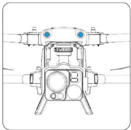
natural_image
Technical line drawing of a mechanical device with blue circular components and control knobs (no text or symbols)Fig 2-1 Front and rear visual lens modules of the aircraft

natural_image
Technical line drawing of a mechanical component with mounting holes and central hub (no text or symbols)
natural_image
Top-down schematic of a mechanical device with four arms and central control panel (no text or symbols)Fig 2-2 Upper left, upper right, and bottom visual lens modules of the aircraft

Warning
- Do not block the lenses of the visual sensing system during flight, as it will affect the visual obstacle avoidance performance of the aircraft, potentially leading to flight accidents.
The millimeter-wave radar sensing system senses the distances and positions of obstacles by emitting electromagnetic waves. According to the regulations of different countries and regions, the millimeter-wave radar sensing system of the aircraft can either integrate six 60 GHz millimeter-wave radars inside the fuselage in six directions (front, rear, left, right, top, and bottom) or integrate a 24 GHz millimeter-wave radar under the fuselage for sensing.

Note
- For detail frequency bands and Effective Isotropic Radiated Power (EIRP) data of the millimeter-wave radar, see Appendix A "A.1 Aircraft".
- For the six millimeter-wave radars used in the Autel Alpha aircraft, the front, rear, left, right, and top millimeter-wave radars use the 60 GHz frequency band, while the frequency band used for the bottom millimeter-wave radar depends on local regulations.
- Please be noted that the frequency band of the millimeter-wave radar is a hardware parameter, which cannot be adjusted through software. Autel Robotics ensures that the millimeter-wave radar frequency band of the Autel Alpha aircraft complies with local legal regulations.
2.6.2 Observation Range
■ Observation Range of Visual Sensing System
By using fisheye lenses, the visual sensing system achieves a 360^ field of view (FOV) in both horizontal and vertical directions, allowing for 720^ all-around observation.
Important
- The visual obstacle avoidance performance of the visual sensing system is not 100% reliable, as the system may be affected by ambient lighting and object surface texture. When the visual obstacle avoidance system is enabled during flight, always pay attention to the image transmission screen in the Autel Enterprise App.
■ Observation Range of Millimeter-wave Radar Sensing System
Note
- Please be aware that millimeter-wave radars of different frequency bands may have varying observation performance.


Fig 2-3 Observation Range of Millimeter-wave Radars
Warning
- The obstacle avoidance distance of the millimeter-wave radar sensing system varies with the obstacle's ability to reflect electromagnetic waves and its surface size.
- The gray area represents the blind spot of a millimeter-wave radar, where the radar cannot detect obstacles.
■ Observation Range of Radar and Visual Sensing Systems
With the integration of radar and visual sensing systems, the aircraft achieves 720° omnidirectional obstacle avoidance and supports nighttime obstacle avoidance.
Note
- If the aircraft uses a 60 GHz bottom millimeter-wave radar, it supports nighttime obstacle avoidance by millimeter-wave radars.
- If the aircraft uses a 24 GHz bottom millimeter-wave radar, the front, rear, left, right and top millimeter-wave radars are disabled by default. The aircraft does not support nighttime obstacle avoidance by millimeter-wave radars and only supports visual obstacle avoidance
in good lighting conditions. Additionally, it uses the bottom millimeter-wave radar only for assisted landing.
2.6.3 Visual Positioning Function
The aircraft supports the visual positioning function even without GNSS signals. It means that the aircraft can provide flight positioning capability in case of poor or no GNSS signal to ensure flight safety.
When there is GNSS positioning information, the visual positioning function supplements the aircraft's position information, enhancing positioning accuracy.
When there is no GNSS signal and the environment and height cannot meet the visual sensing system, that is, when there is no GNSS signal and visual positioning failure at the same time, the ATTI mode will be activated.

Warning
- If you do not have extensive flight experience, do not fly the aircraft beyond your visual line of sight.
- When the aircraft relies on visual positioning to fly, please do not approach mirror reflection areas such as water or snow. When the GNSS signal is poor, please make sure that the aircraft flies in a well-lit environment and over object surfaces with clear texture.

Tip
In the event of GNSS signal loss or weakening during flight, the remote controller will display the following warning prompts:
- If the takeoff point is inaccurate: The Autel Enterprise App will display a warning saying "GNSS signal is weak, home point may have deviation." with a corresponding verbal warning.
- If GNSS signal is weak: The Autel Enterprise App will show a warning saying "GNSS signal is weak, please fly away from buildings." with a corresponding verbal warning.
- If GNSS is being spoofed: The Autel Enterprise App will display a warning saying "Aircraft is being subjected to GNSS spoofing." with a corresponding verbal warning.
- If the aircraft is in ATTI mode, the Autel Enterprise App will show a warning saying "No GNSS and visual positioning, please be cautious." with a corresponding verbal warning.
- If GNSS is manually turned off and aircraft positioning is available, the Autel Enterprise App will show a warning saying "GNSS is turned off, visual positioning signal is normal/weak, please fly with caution." with a corresponding verbal warning.
- If GNSS is manually turned off and aircraft positioning is lost, the Autel Enterprise App will display a warning saying "No GNSS and visual positioning, please be cautious." with a corresponding verbal warning.
2.6.4 Visual Obstacle Avoidance Function
The visual obstacle avoidance function is suitable for scenarios where the aircraft flies in a well-lit environment and encounters obstacles that are not too sparse during the flight, such as sparse fine wire meshes or small branches at the outer edges of trees. Additionally, due to inertia, the aircraft needs to brake at an effective distance under control. The flight control system limits the aircraft's attitude angle to no more than 30^ and the maximum flight speed to less than 15 meters per second during deceleration. For more information, see "6.5.2 OA Settings" in Chapter 6.

Warning
- The obstacle avoidance function of the aircraft cannot be enabled in Ludicrous mode.
2.6.5 Precautions for Using Obstacle Avoidance Systems
The measurement accuracy of the visual sensing system is easily affected by factors such as light intensity and object surface texture. Exercise caution when using the visual sensing system in the following scenarios:
- Flying over pure-colored surfaces (e.g., pure white, pure black, pure red, and pure green) and low-texture surfaces.
● Flying over surfaces with strong reflections.
● Flying over moving objects (e.g., crowds, swaying reeds, bushes, and grasses).
● Flying over water surfaces or transparent object surfaces. - Flying in environments with rapid and intense changes in lighting or direct exposure to strong light sources.
- Flying over extremely dim (with light intensity of less than 15 lux) or extremely bright object surfaces.
● Flying over small obstacles (e.g., iron wires, electric wires, and tree branches).
● Lenses contamination (e.g., water droplets and fingerprints).
● Flying in low-visibility conditions (e.g., heavy fog and heavy snow).
● Flying at an altitude below 2 meters with a very fast flight speed.
The millimeter-wave radar sensing system operates as an auxiliary enhancement system for visual obstacle avoidance and can work continuously throughout the day.

Note
- Please be noted that when flying in low-light conditions (such as at night), the aircraft's visual perception system is affected, so the obstacle avoidance is not working.
- If you need to fly in low-light conditions (such as at night), please confirm that the aircraft is 60 GHz version with downward millimeter-wave radar (aircraft with the 24 GHz version of downward radar does not have nighttime millimeter-wave obstacle avoidance capability). Additionally, please operate cautiously in nighttime flights, as in the nighttime obstacle avoidance is not 100% functional. It is recommended to fly in open areas.
2.7 Auto-return
The aircraft is equipped with an auto-return function. When the GNSS signal is good, once the auto-return condition is triggered, the aircraft automatically returns to the home point and lands to avoid possible accidents.
The aircraft provides three methods of activating the auto-return function: manual auto-return activation, low battery auto-return activation, and behavior-based auto-return activation.

Note
- Home point: the landing point of the aircraft during an auto-return flight. In the Autel Enterprise App, you can set the home point of the aircraft as "Aircraft" or "RC". For more information, see "6.5.1 Flight Control Parameter Setting" in Chapter 6.
- If no home point is set in the Autel Enterprise App, the take-off point is used as the home point.
- During an auto-return, the control function of the remote controller for the aircraft is disabled. In this case, you can quickly press the pause button "⑪" on the remote controller or long press it for two seconds or pull the pitch stick to pause or exit the auto-return function and regain control of the aircraft. For more information, see "4.11.2 Take-off/Return-to-Home Button and Pause Button" in Chapter 4.

Warning
- When the GNSS signal is poor, the auto-return function cannot be activated.
- If the obstacle avoidance system is disabled during an auto-return flight, the aircraft will not be able to automatically avoid obstacles.
- If the home point of an auto-return flight is not suitable for the aircraft to land (such as uneven grounds and crowds), please exit the auto-return function first, and then manually assume control to land.
2.7.1 Manual Auto-return Activation
During the flight, you can long press the return-to-home button “💡” on the remote controller for 2 seconds to manually activate the auto-return function.
2.7.2 Low Battery Auto-return Activation
During the flight, to prevent unnecessary risks caused by insufficient power of the smart battery, the aircraft will automatically check whether the current battery level is sufficient based on the aircraft's current position.
If the current battery level is only enough to complete the return journey, the Autel Enterprise App will prompt a warning saying "The remaining battery is only enough for Return to Home. The aircraft will Return to Home in 10s." to reminder users to decide i to execute low battery auto-return. If you choose to execute it or don't take any action within 10 seconds, the aircraft will initiate low battery auto-return after 10 seconds.
If you cancel the execution and continue flying with a low battery level, when the battery level is only enough for landing, the aircraft will activate a critically low battery landing. This landing process cannot be canceled, and you will lose control of the aircraft in this process.

Tip
- The low battery auto-return and critically low battery landing mentioned here have no direct relation with the low battery warning and critically low battery warning set in the Autel Enterprise App.

Warning
- When the low battery auto-return is triggered in the aircraft, the auto-return process should not be canceled. Otherwise, the aircraft may be unable to return to the home point due to insufficient power.
- Try not to let the aircraft enter the critically low battery landing process. Once the critically low battery landing process is initiated, regardless of whether the landing point meets safe landing standards, the aircraft will forcibly land, which may lead to aircraft damage.
- When the Autel Enterprise App displays a warning alert, it should be processed according to the corresponding references immediately.
2.7.3 Behavior-based Auto-return Activation
During a flight mission, if "Finish Action" is set to "Auto RTH", the aircraft will activate auto-return after completing the mission; if "Signal Loss Action" is set to "Auto RTH", when the remote controller disconnects from the aircraft for 4 seconds, the aircraft will activate auto-return. For more information, see "6.9 Flight Missions" in Chapter 6.
During the flight, if "Lost Action" is set to "Return to Home", when the remote controller disconnects from the aircraft for 4 seconds, the Autel Enterprise App will display a warning saying "Aircraft disconnected." and the aircraft will activate auto-return. For more information, see "6.5.1 Flight Control Parameter Setting" in Chapter 6.

Tip
- In the Autel Enterprise App, "Lost Action" is set to "Return to Home" by default.
- Within 4 seconds of the remote controller disconnecting from the aircraft, the aircraft will continuously decelerate and attempt to reconnect the remote controller. If the reconnection is not successful within 4 seconds, the aircraft will activate the lost action auto-return.
- During the lost action auto-return process, even if the aircraft resumes connection with the remote controller, the aircraft will continue to execute auto-return.
2.7.4 Auto-return Mechanism
Table 2-1 Auto-return Mechanism
| Aircraft distance when the return mechanism is triggered | Return-to-Home Mechanism |
| Distance from the home point ≤ 10 meters | The aircraft returns to the home point at the current altitude. |
| 10 metersIf the current flight altitude is lower than 20 meters, the aircraft ascends to the altitude of 20 meters and returns to the home point.If the current flight altitude is higher than 20 meters, the aircraft returns to the home point at the current altitude. | If the current flight altitude is lower than 20 meters, the aircraft ascends to the altitude of 20 meters and returns to the home point.If the current flight altitude is higher than 20 meters, the aircraft returns to the home point at the current altitude. |
| 25 meters < Distance from the home point ≤ 50 meters | If the current flight altitude is lower than 30 meters, the aircraft ascends to the altitude of 30 meters and returns to the home point.If the current flight altitude is higher than 30 meters, the aircraft returns to the home point at the current altitude. |
| Distance from the home point > 50 meters | If the flight altitude is lower than the set RTH altitude, the aircraft ascends to the RTH altitude.If the flight altitude is higher than the set RTH altitude, the aircraft returns to the home point at the current altitude. |

Note
● Home point: the point where the aircraft will return and land during an auto-return.
- Aircraft distance refers to the horizontal distance from the current aircraft to the home point.
2.7.5 Auto-return Obstacle Avoidance Process
When the obstacle avoidance system is enabled and the visual sensing system is in appropriate lighting conditions, the aircraft will achieve obstacle avoidance during the return process. The specific situations are as follows:
- During manual flight, in case of a lost action auto-return, low battery auto-return, or manual activation of auto-return, when an obstacle is detected in front of the aircraft, the aircraft will automatically brake within the set brake distance and automatically ascend to avoid the obstacle until it can safely fly over it.
- During flight missions, the obstacle avoidance mode is set to "Bypass". In the case of a lost action auto-return, low battery auto-return, or mission completion auto-return, when an
obstacle is detected in front of the aircraft, the aircraft will automatically brake within the set brake distance and autonomously choose a random direction from the left, right, or upward directions to bypass the obstacle.
Important
- During the obstacle avoidance process, if the aircraft's ascent altitude reaches the maximum altitude limit and obstacle avoidance is not yet achieved, the aircraft will hover in place until a critically low battery landing is triggered. In this case, please manually take control of the aircraft in advance.
- When the obstacle avoidance mode is set to "Bypass", the aircraft will prioritize planning to bypass the obstacle from the left or right direction. If neither left nor right directions are feasible, it will choose to bypass the obstacle from above.
- During flight missions, if the obstacle avoidance mode is set to "Off", the aircraft will not have obstacle avoidance capabilities.
2.7.6 Landing Protection Function
When the landing protection function is enabled, the aircraft will assess whether the ground conditions are suitable for landing before landing. For more information, see "6.5.2 OA Settings" in Chapter 6.
During the auto-return process, when the aircraft reaches above the home point and the landing protection function is enabled, the aircraft will execute the following strategies:
- If the landing protection function detects that the ground is suitable for landing, the aircraft will land directly.
- If the landing protection function detects that the ground is not suitable for landing (e.g., uneven ground or water below), the aircraft will keep hovering, send a prompt in the Autel Enterprise App, and wait for you to take action. In this case, the aircraft will start descending only when a critically low battery landing is triggered, and you cannot cancel this process.
- If the landing protection function cannot detect ground conditions, the aircraft will descend to an altitude of 1.2 meter above the ground and enter the assisted landing process.
Note
- Assisted landing: During the landing process, when the aircraft reaches an altitude of 1.2 meter above the ground, it will automatically descend slowly and you do not need to lower the throttle stick.
- Before entering the assisted landing process, make sure that the landing point is suitable for the aircraft to land.
2.8 Rebuilding the C2 Link
To ensure the safety and controllability of flight behaviors, the Autel Alpha aircraft will stay in reconnection status and constantly attempt to reestablish a connection with the ground control
station (remote controller) after losing the C2 link. In practice, this process is divided into the following stages:
- Within the first 4 seconds after the link is disconnected, the aircraft will automatically decelerate and attempt to restore the C2 link. If the connection is restored within 4 seconds, the remote controller regains control of the aircraft.
- If the link is not restored within 4 seconds, the aircraft will automatically trigger the lost action. At this point, the aircraft will automatically execute relevant flight control actions according to the set lost actions.
- During the execution of a lost action, the aircraft will continue its attempts to restore the C2 link. When the aircraft successfully restores the C2 link with the remote controller, the remote controller still cannot control the flight of the aircraft. To make the remote controller regain control of the aircraft, you must long press the pause button “” on the remote controller for 2 seconds or pull the pitch stick to exit the lost action.
| Tip |
| ● During the flight, as long as the aircraft and the remote controller can communicate normally, the C2 link will remain active.● If there are decoding errors that persist for a certain duration, leading to communication failure, the C2 link will be disconnected, and the aircraft will enter the reconnection status.● The lost actions of the Autel Alpha aircraft include RTH, hover, and land.● If Autel Alpha aircraft lost connection with C2 link, the Autel Enterprise App will display a warning saying “Aircraft disconnected.” with a corresponding verbal warning.● For details about pitch stick, please refer to “4.10 Selecting Stick Mode”. |
2.9 Flight Restrictions and Unlocking Restricted Zones
| Important |
| ● Before flying, always carefully plan out the airspace in which you intend to fly in accordance with local laws and regulations. |
2.9.1 Geofencing System
Autel Robotics has developed a geofencing system for its aircraft to ensure safe and legal flights. This system can provide real-time updates on airspace restriction information worldwide. In different restricted zones, the flight functions of the aircraft are subject to varying degrees of restrictions. The geofencing system also supports the function of unlocking restricted zones. If you need to perform a flight mission in a specific restricted zone, you need to obtain legal authorization for unlocking the restricted zone, and then the relevant flight restriction of the aircraft will be unlocked within the authorization validity period.
The geofencing system does not strictly follow local laws and regulations. Before each flight, you should consult and understand local laws, regulations, and regulatory requirements to ensure flight safety.
The flight control system of the Autel Alpha aircraft is pre-configured with the geofencing system. Before each flight, make sure that the remote controller can connect to the Internet to automatically update airspace restriction information and synchronously upload it to the aircraft. During the flight, relevant airspace restriction information will be synchronously displayed in the Autel Enterprise App to ensure the safe and legal flight of the aircraft.

Tip
- Due to information lag, the airspace restriction information provided by the geofencing system may not always be completely consistent with the latest local laws and regulations. All information is subject to local laws and regulations.
- For temporary airspace restrictions, Autel Robotics can obtain the relevant regulatory announcements in a timely manner and synchronously upload the relevant airspace restriction information to the geofencing system. When you take flight actions in relevant zones, be sure to synchronize and update flight airspace restriction information.

Important
- When GNSS signal is poor, Autel Enterprise App will prompt "GNSS signal is weak, and geo-awareness may be disabled". At this time, the geofencing system may not function properly.
2.9.2 Restricted Zones
The geofencing system divides airspace restrictions into four categories: no-fly zones, restricted altitude zones, caution zones, and unlocked zones. The Autel Enterprise App will provide different prompts based on the specific zone.
Table 2-2 Flight Restrictions of Restricted Zones
| Restricted Zones Flight | Restriction Description |
| No-Fly Zones(appear in red on the map) | No-fly zones are divided into permanent no-fly zones and temporary no-fly zones.Permanent no-fly zones: The zones are pre-configured in the geofencing system at the factory and are regularly updated.Temporary no-fly zones: The zones are added by Autel Robotics in the geofencing system backend.Update method: After the remote controller is connected to the Internet, it will automatically retrieve update information related to no-fly zones and push it to the aircraft. Flight restrictions: Aircraft cannot take off or fly in no-fly zones. If you obtain authorization from relevant authorities to fly in a no-fly zone, contact Autel Robotics to request for unlocking the zone. |
| Restricted Altitude Zones (appear in grey on the map) | Autel Robotics only provides altitude restrictions setting, allowing users to set the altitude limit accordingly. Update process: Users enable height restrictions and set the altitude limit within the Autel Enterprise App, based on the local legal regulations of the country and region. For detailed information, see "2.10 Altitude and Distance Limits" in Chapter 2 and "6.5.1 Flight Control Parameter Settings" in Chapter 6. Flight restrictions: When flying in a restricted altitude zone, the actual flight altitude of the aircraft will not exceed the set altitude limit. |
| Warning Zones (appear in yellow on the map) | Warning zones are pre-configured in the geofencing system at the factory and are regularly updated. Update method: After the remote controller is connected to the Internet, it will automatically retrieve update information related to warning zones and push it to the aircraft. Flight restrictions: In a warning zone, an aircraft can fly unrestrictedly (relevant flights must comply with local regulations). |
| Unlocked Zones (appear in blue on the map) | If you unlock a no-fly zone with a valid permit, you can legally fly the aircraft within the validity period in the unlocked zone. |

Tip
In the Autel Enterprise App, if you tap on a restricted zone on the map, the following geofencing information will be displayed for this zone:
- No-fly Zone: zone name, zone level (no-fly zone), region (prefecture-level city), and no-fly time (visible only for temporary no-fly zones).
- Restricted altitude zone: zone name, zone level (restricted altitude zone), altitude limit (AGL), and region (prefecture-level city).
- Warning zone: zone name, zone level (warning zone), altitude limit (AGL), and region (prefecture-level city).
- Unlocked zone: zone name, zone level (unlocked zone), altitude limit (AGL), region (prefecture-level city), and validity period.

Note
- Before any flight, users must fully understand the local regulations regarding altitude restrictions for unmanned aerial vehicles (UAVs) and set them in the Autel Enterprise App.
- It is important to note that it is not suggested to fly cross regions with different legal altitude restrictions. The altitude limit setting is only effective for the takeoff area, the limit may not comply with regulations in neighboring regions. Users should adjust the corresponding altitude limits when flying across different regions.
An aircraft in flight has a specific initial velocity. To prevent the aircraft from accidentally entering no-fly zones (before unlocking) and warning zones, a buffer zone with a horizontal distance of 200-meter and a vertical distance of 120-meter is set beyond the boundaries of these zones in the geofencing system.
Table 2-3 Buffer Zone Details
| Buffer Zone Type | Buffer Zone Details |
| Buffer zones of no-fly zones | When an aircraft flies from the outside toward a no-fly zone: When the aircraft approaches the buffer zone boundary, the Autel Enterprise App will display a warning alert says “The aircraft is close to the no-fly zone.” and the aircraft will automatically start to decelerate and eventually brake and hover within the buffer zone. |
| Buffer zones of warning zones | When an aircraft flies from the outside toward a warning zone: The aircraft can directly fly into the restricted altitude zone without limitation.When the aircraft approaches the warning zone boundary, the Autel Enterprise App will display a warning alert says “The aircraft is close to the warning zone.” and after enter the warning zone, the App will display “Aircraft enters warning zone” to remind users to be cautious. |

Note
- When there is a GNSS signal, if an aircraft accidentally enters a no-fly zone while the aircraft is still locked from the zone, the aircraft will automatically land upon regaining the GNSS signal. During the landing process, the throttle stick will not work, but you can control the horizontal movement of the aircraft.
- When there is no GNSS signal, if an aircraft accidentally enters a restricted altitude zone, the aircraft will automatically descend to the altitude limit upon regaining the GNSS signal. During the descending process, the throttle stick will not work, but you can control the horizontal movement of the aircraft.
- When an aircraft is hovering in the buffer zone, you can control the aircraft to exit the buffer zone along the normal direction of the boundary.
For flights in an unlocked zone, if an aircraft is within the authorized airspace and validity period specified in the permit, the aircraft can fly normally in the zone. Once the aircraft flies beyond the authorized airspace or reaches the validity period, the aircraft will comply with the airspace restrictions of the current area.
2.9.3 UGZ Import
The aircraft supports for importing the UGZ (UAS Geographical Zones) file, if users get the no-fly zone data files of their own country or region, they can upload the data to the aircraft's flight
control system. When the aircraft approaches relevant airspace during flight, it will execute corresponding responses to ensure flight safety (including warnings and slow down and other actions).

Tip
- The UGZ import supports JSON format. Users can import no-fly zone data files published by local aviation authorities.
- Operation path: Copy the JSON file into the root path of the remote controller. On the map interface of the Autel Enterprise App, tap "☐" > "Import Geo-fence" on the right side. Follow the on-screen instructions to complete the operations.
2.9.4 Unlocking No-Fly Zones
To apply for unlocking a specific airspace within a no-fly zone, prepare the following information in advance according to your flight plan:
- Identity and contact information of the applicant.
- Unlock permit: a scanned copy or image of the valid permit for the flight application issued by local authorities (local public security bureau, aviation management department, or any other relevant organization/agency).
- Unlocked zone: a cylindrical area. It includes the following information:
- Name of the unlocked zone.
- Coordinates of the center point of the flight airspace plane (latitude and longitude, with 6 decimal places).
-
Radius of the flight airspace plane (in meters, with 2 decimal places).
● Flight altitude (in meters, with 2 decimal places). -
Unlock date: Enter the unlock date according to the valid permit. The date is recommended to be accurate to day/hour/second.
-
Aircraft S/N (Serial number): Multiple serial numbers can be applied at once.
-
Autel account of UAS operator: Multiple accounts can be applied at once.
Log in to the official website of Autel Robotics at www.autelrobotics.com/service/noflight/, enter the relevant information, and complete the waiver application.
After the unlocking application is approved, you will obtain an unlock permit. The permit contains the aircraft serial number, UAS operator account, and unlocked zone (including the validity period).

Tip
- After the waiver application is submitted, it will be approved within 24 hours, and unlocking will be completed within 48 hours. Please make a reasonable flight plan in advance.
2.10 Altitude and Distance Limits
The altitude limit is the maximum flight altitude of the aircraft, while the distance limit is the maximum radius (distance from the take-off point) that the aircraft can fly.
You can set altitude and distance limits in the Autel Enterprise App to ensure the safe flight of the aircraft. For more information, see "6.5.1 Flight Control Parameter Setting" in Chapter 6.

Fig 2-4 Diagram of altitude and distance limits

Tip
- In the Autel Enterprise App, the altitude limit should be set between 20 meters and 800 meters, and the distance limit should be set between 20 meters and 5000 meters. During actual flights, the maximum altitude limit should be set no greater than the maximum altitude specified by local laws and regulations. For example, Chinese Mainland, the United States, and the European Union all limit the maximum flight altitude of aircraft to no more than 120 meters or 400 feet.
- When setting the maximum altitude limit, consider the reasonableness of the RTH altitude, which should not exceed the maximum altitude limit.
- The RTH altitude should be set higher than the altitude of the highest obstacle in the flight area.
2.11 Aircraft Calibration
2.11.1 Compass Calibration
The compass (magnetometer) has been calibrated at the factory, and no user calibration is required under normal conditions.
If the Autel Enterprise App prompts that the compass displays an error message, the flight direction of the aircraft is inconsistent with the control input direction of the remote controller, or the flight location deviates too much from the calibration location, please follow the steps below to calibrate it.
Important
- The compass is very easy to be affected by electromagnetic interference. Electromagnetic interference may lead to compass errors and degradation in flight quality.
- Please choose an open outdoor area for calibration.
- During calibration, please stay away from areas with a strong magnetic field or large metal objects, such as magnetic ore mines, parking lots, construction areas with underground reinforcing steel bars, underground areas, or locations near overhead power transmission lines.
- During calibration, do not carry ferromagnetic materials or metal objects on your person, such as mobile phones and watches.
- During the calibration process, please stay away from charged objects and make the aircraft fly 1.5 meters above the ground.
- During the calibration process, please do not turn off the power of the aircraft or start the motors.
Table 2-4 Compass Calibration
| Step | Operation | Diagram |
| 1 | After turning on the aircraft and the remote controller, tap "☐" > "☐" > "☐" > "Compass Calibration" > "Start Calibration" in the main interface of the Autel Enterprise App.When the calibration process begins, the rear arm light of the aircraft turns yellow and blinks. | < Compass Calibration · Please stay away from metal or charged objects, and keep the aircraft away the ground 1.5m. · Do not power off the aircraft or start the motors.Start calibration · Please stay away from metal or charged objects, and keep the aircraft away the ground 1.5m. · Do not power off the aircraft or start the motors.Start calibration |
<
Compass Calibration
2
Hold the aircraft to keep it in a horizontal direction.
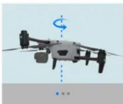
Rotate the aircraft 360^ horizontally until the rear arm light of the aircraft turns green and blinks.
natural_image
Drone with directional arrow and control panel, no visible text or symbolsStep 1
Rotate the aircraft horizontally 360° as shown.
| 3 | Hold the aircraft to keep it in a vertical direction with the nose up.Rotate the aircraft 360° horizontally until the rear arm light of the aircraft turns green and blinks. | Compuse Calibration | |
 | Step 2Rotate the aircraft vertically 360° as shown. | ||
Compass Calibration
4
Hold the aircraft to keep it with the nose to the left and the side down.
Rotate the aircraft 360° horizontally until the rear arm light of the aircraft turns green and is always on.

natural_image
Diagram of a quadcopter drone with rotation arrow and ground level indicator (no text or symbols)Step 3
Side rotate the aircraft 360° as shown

Tip
- Please perform the calibration steps according to the tips shown in the compass calibration interface of the Autel Enterprise App.
- If the calibration fails, the rear arm light of the aircraft will turn red and is always on, and the above steps should be repeated at this time.
- If the compass still cannot work properly after the calibration, fly the aircraft to other places and calibrate the compass again.
2.11.2 IMU Calibration
The IMU (Inertial Measurement Unit) of the aircraft has been calibrated at the factory, and no user calibration is required under normal conditions.
If the acceleration and angular velocity of the aircraft are abnormal, please follow the steps below to calibrate it.

Important
- Please place the aircraft according to the tips shown in the IMU calibration interface of the Autel Enterprise App, and keep the aircraft in a static state.
- Please place the aircraft on flat ground, and do not move, shut down, or restart the aircraft during the calibration process.
● During IMU calibration, the gimbal will not work.
Table 2-5 IMU Calibration
| Step | Operation | Diagram |
| 1 | After turning on the aircraft and the remote controller, tap "◇" > "◇" > "◇" > "IMU Calibration" > "Start Calibration" in the main interface of the Autel Enterprise App.When the calibration process begins, the rear arm light of the aircraft turns yellow and blinks. |  · Please place the aircraft on leveled surface. Do not move, power off or reboot the aircraft during calibration.Start calibration · Please place the aircraft on leveled surface. Do not move, power off or reboot the aircraft during calibration.Start calibration |
| 2 | Fold up the arms and place the aircraft flat on the ground until the rear arm light of the aircraft turns green and blinks. | 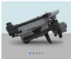 Step 1Please fold all the arms and place the aircraft on the leveled surface.Calibrating.. Step 1Please fold all the arms and place the aircraft on the leveled surface.Calibrating.. |
| 3 | Turn the aircraft over 180° and lay the aircraft facing up until the rear arm light of the aircraft turns green and blinks.Please pay attention to protecting the upward-looking camera lens. |  Step 2Turn over the aircraft and lay it on the leveled surface with the bottom facing up.Calibrating.. Step 2Turn over the aircraft and lay it on the leveled surface with the bottom facing up.Calibrating.. |
| 4 | Put the left side of the aircraft flat on the ground until the rear arm light of the aircraft turns green and blinks. | IMU Calibration Step 3 Turn the aircraft to lay the left side on the leveled surface. Calibrating... |
| 5 | Put the right side of the aircraft flat on the ground until the rear arm light of the aircraft turns green and blinks. | IMU Calibration Step 4 Turn the aircraft to lay the right side on the leveled surface. Calibrating... |
| 6 | Fold the arms, turn the aircraft nose up, and lay it on the leveled surface until the rear arm light of the aircraft turns green and is always on. Be careful not to bump the rear camera lens. | IMU Calibration Step 5 Turn the aircraft nose up and lay it on the leveled surface. Calibrating... |

2.11.3 Gimbal Calibration
The gimbal of the aircraft has been calibrated at the factory, and no user calibration is required under normal conditions.
If the rotation angle of the gimbal is abnormal, please follow the steps below to calibrate it.
Table 2-6 Gimbal Calibration
| Step | Operation | Diagram |
| 1 | Place the aircraft on a flat ground. After turning on the aircraft and the remote controller, keep the aircraft in a static state.In the main interface of the Autel Enterprise App, tap “”“Gimbal Calibration” > “Start Calibration”. | < Gimbal Calibration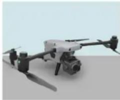 · Please place the aircraft on flat ground and keep the aircraft stationary during calibration.Start calibration · Please place the aircraft on flat ground and keep the aircraft stationary during calibration.Start calibration |
| 2 | Wait for the calibration progress bar to reach 100%. When “Calibration Successful” is displayed on the screen, the gimbal is successfully calibrated. | < Gimbal Calibration Please don't power off the aircraft Please don't power off the aircraft |
2.12 Emergency Stop Propellers During Flight
During flight, if the motors of the aircraft experience power damage or failure (e.g., damaged or missing propellers and motor failure) that makes the aircraft out of control, you can enable the "Emergency Stop Propellers During Flight" function. At the same time, you need to manipulate the dual command sticks on the remote controller inward or outward to forcibly stop propeller rotation and allow the aircraft to descend freely for an emergency landing. This can reduce the potential damage to property and harm to ground personnel caused by aircraft malfunctions.
In the event of an aircraft malfunction, you should first attempt to manipulate the command sticks to move the aircraft away from crowds or buildings and lower the altitude and horizontal speed of the aircraft before enabling the emergency propeller stop function. For how to enable this function, see "6.5.8 More" in Chapter 6.
Important
- If you stop the propellers when the aircraft has an initial velocity, the aircraft will fall along a parabolic trajectory. If the trajectory is unpredictable, do not stop the propellers.
- After completing an emergency landing, contact Autel Robotics promptly for a power system inspection and maintenance.
2.13 Mid-flight Sensing
Automatic Dependent Surveillance-Broadcast (ADS-B) is a manned aircraft monitoring technology that allows a manned aircraft to determine its position using satellite navigation systems and broadcast the information regularly, making the aircraft trackable. Other aircraft can receive the information to achieve attitude awareness and autonomous avoidance.
The Autel Alpha aircraft is equipped with ADS-B receivers that can receive flight information broadcast by ADS-B transmitters that support the 1090ES and UAT standards within a range of 10 kilometers. By analyzing the received flight information, the position, altitude, course, and speed of the manned aircraft will be obtained, and the obtained information will be compared with the current position, altitude, course, and speed information of the aircraft. The Autel Enterprise App will provide real-time risk warnings, reminding users to plan flight paths rationally and pay attention to avoidance.
Important
- The aircraft has been pre-configured with the ADS-B receiver hardware at the factory. The mid-flight sensing function will be available in subsequent versions. Please update the aircraft firmware in a timely manner.
- Operation path: Tap “☐”> “☐” > “☐” > “Safety” > “Receive ADS-B” in the main interface of the Autel Enterprise App, and follow the on-screen instructions to perform relevant operations. For more information, see “6.5.8 More” in Chapter 6.
2.14 Direct Remote Identification
The Direct Remote Identification (DRI) system allows for uploading the registration number (Remote ID) of a UAS operator to the system. During flight, it can actively broadcast some non-sensitive data to mobile devices within its broadcast range in real time via an open, documented transmission protocol. The non-sensitive data includes the registration number of the operator, the unique serial number, timestamp, geographical location, altitude above ground level or take-off point, route measured clockwise from true north, and ground speed of the unmanned aircraft, and the geographical location of the operator (if available, otherwise the geographical location of the take-off point). This system not only effectively controls potential risks to public safety posed by unmanned aircraft during flight but also provides effective information and data tools for unmanned aircraft flight regulation.
The Autel Alpha aircraft supports the DRI system and uses Wi-Fi (Wi-Fi Beacon, 802.11n) for broadcasting. To enable the DRI system, configure it in the Autel Enterprise App.

Tip
- Operation path: On the main interface of the Autel Enterprise App, tap "☐" > "☐" > "☐" > "Safety" > "Remote ID", and follow the on-screen instructions to perform relevant operations. For more information, see "6.5.8 More" in Chapter 6.
2.15 Standard Flight Operation Process
2.15.1 Pre-Flight Checklist
Before each flight, please follow the steps below to perform a comprehensive pre-flight check to ensure flight safety:
● Make sure that the batteries of the aircraft and remote controller are fully charged, and the two batteries of the aircraft is installed in place, with the battery unlock lever in a lock state.
● Make sure that the propellers of the aircraft are installed properly, tightly without damage or deformation, the motor and propellers are clean and free of foreign objects, and the propellers and arms are fully extended.
● Make sure that the microSD card is inserted into the gimbal, and that the rubber protective cover on the microSD card slot is closed firmly. Otherwise, the protection performance of the gimbal will be affected.
● Make sure the gimbal camera is well mounted on the aircraft and the gimbal unlock button is aligned with the lock symbol on the gimbal connector.
● Make sure that gimbal protective cover has been removed, the vision cameras of the aircraft, the lens of the gimbal, and the lens of the auxiliary light are free from foreign objects, dirt, or fingerprints, and are not blocked by loads or other accessories on the fuselage.
● Make sure that the three-axis movement of the gimbal is in a normal state.
● Make sure that the rubber protective cover on the fuselage is closed firmly. Otherwise, the protection performance of the aircraft will be affected.
● Make sure that the antenna of the remote control is unfolded.
- Place the aircraft in an open and flat area outdoors and make sure that there are no obstacles, buildings, trees, etc. around. You should stand at least 10 meters away from the tail of the aircraft when operating.
● Make sure that after the aircraft is powered on, the aircraft and the remote controller are connected, and the aircraft motors, gimbal, and camera are working normally.
● Make sure that the aircraft, remote controller, etc. have been upgraded to the latest version as prompted.
● Make sure that all warnings and errors displayed on the Autel Enterprise App are handled.
- Enter the Autel Enterprise App setting page to set the flight control parameters, obstacle avoidance system, stick mode, and other related flight safety parameters, and be familiar with the flight operation, so as to ensure that the parameter settings meet your own needs and guarantee flight safety.
- If multiple aircraft are flying at the same time, please keep an appropriate air distance to avoid any accidents.
2.15.2 Basic Flight Process
The aircraft provides three command stick modes: Mode 1, Mode 2, and Mode 3. Each mode controls the aircraft differently. The default mode is Mode 2. You can switch the mode in the Autel Enterprise App according to your control habit (For how to switch the mode, see "6.5.3 RC Settings" in Chapter 6). The following is the basic operation of aircraft flight:
-
Please refer to "2.15.1 Pre-Flight Checklist" to complete the preparations before flight.
-
Place the aircraft in an open and flat area outdoors and make sure that there are no obstacles, buildings, trees, etc. around.
- Press and hold the battery power button for 2 seconds to turn on the power of the aircraft, and wait for the rear arm light to turn green and blinks slowly (indicating that the current status is normal).
-
Long press the power button of the remote controller for 3 seconds to turn on the remote controller.
● Stand at least 10 meters away from the rear arms of the aircraft. -
Please refer to "4.10.3 Starting/Stopping the Aircraft Motor" in Chapter 4 to use the remote controller to start the aircraft and take off.
-
Please refer to "4.10.1 Stick Modes" and "4.10.2 Setting Stick Mode" in Chapter 4 to control the aircraft carefully.
-
Please refer to "4.10.3 Starting/Stopping the Aircraft Motor" in Chapter 4 to land the aircraft, and then turn off the motors.
2.16 List of Safeguard
Before flight, please know the following safeguard information, which helps you handle abnormal situations in a correct and safe way.
Table 2-7 List of Safeguard
| No. | Safety Function | Refer To |
| 1 | Auto Return Home | “2.7 Auto-return” in this chapter. |
| 2 | Emergency Stop Propellers During Flight | “2.12 Emergency Stop Propellers During Flight” in this chapter. |
Chapter 3 Aircraft
3.1 Aircraft Activation
When unboxing the product for the first time, you need to activate the Autel Alpha aircraft before using it. By default, the aircraft is pre-paired with the remote controller at the factory. After turning on the aircraft and the remote controller, you will see an activation prompt in the Autel Enterprise App. Please follow the steps in the Autel Enterprise App to activate the aircraft.

Important
- Make sure that the remote controller is connected to the Internet before starting the activation process. Otherwise, activation may fail.
- If activation fails, please contact Autel Robotics After-Sales Support for assistance.
- For how to pair the aircraft with the remote controller, see "4.9 Frequency Pairing With the Remote Controller" in Chapter 4.
3.2 Aircraft Components

Fig 3-1 Aircraft Front View
Table 3-1 Aircraft Front View Details
| No. | Name | Description |
| 1 | RTK Antenna | Used to realize centimeter level accurate positioning. |
| 2 | Front Arm Light | Used to identify the nose direction of the aircraft. |
| 3 | Motor | Used to drive the propeller to rotate. |
| 4 Propeller | Rotates in the air to generate thrust to propel the aircraft forward. | |
| 5 Rear Landing Gear | Used to support the aircraft to avoid damage to the bottom of the fuselage. (with built-in image transmission antenna) | |
| 6 | Forward Visual Sensing System | Used to sense the obstacles ahead and avoid the aircraft from colliding with them. |
| 7 Gimbal Camera | Integrates multiple sensors for stable shooting or measurements during flight. | |
| 8 | Front Support Legs | Used to support the aircraft to avoid damage to the bottom of the fuselage. |

Fig 3-2 Aircraft Rear View
Table 3-2 Aircraft Rear View Details
| No. | Name | Description |
| 9 | Rear Visual Sensing System | Used to sense the obstacles in the rear and avoid the aircraft from colliding with them. |
| 10 | Rear Arm Light | Used to display the current flight status of the aircraft. |
| 11 | Battery Unlock Lever | Move the battery unlock levers outward to unlock the battery and take out the smart batteries from the compartment. |
| 12 | Smart Battery | Used to provide energy for aircraft operation. |
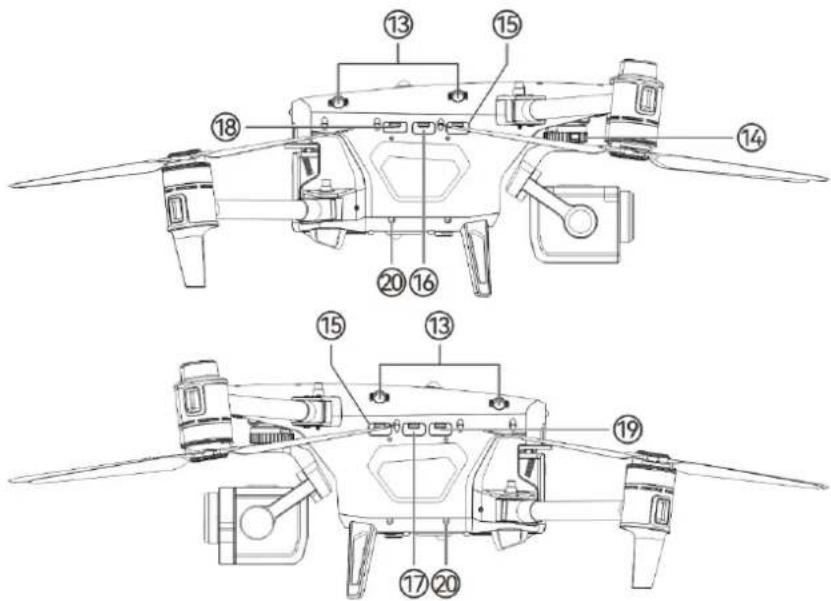
Fig 3-3 Aircraft Side View
Table 3-3 Aircraft Side View Details
| No. | Name | Description |
| 13 | Side Visual Sensing System | Used to sense the obstacles in the left and right sides and avoid the aircraft from colliding with them. |
| 14 | Gimbal Interface Used to connect to the gimbal camera. | |
| 15 | P-Port | PSDK Interface. Additional mounts can be added to the aircraft fuselage through the extension interface, such as speakers, spotlights, and RTK modules. Supports the connection of devices using MIPI protocols. (excludes USB 2.0 Full-Speed devices) |
| 16 | P-Port | PSDK Interface. Additional mounts can be added to the aircraft fuselage through the extension interface, such as speakers, spotlights, and RTK modules.When gimbal is mounted, please connect the gimbal with aircraft via this interface. |
| 17 | O-Port | OSDK interface. The OSDK interface supports the integration of additional high-bandwidth computing unit devices.This interface also allows the connection of PSDK devices using USB. (excludes USB 2.0 Full-Speed devices) |
| 18 | WLAN Interface | Pre-set interface, if the purchased drone version is equipped with relevant hardware, users can insert a mobile data card (nano-SIM card) to provide internet access for the drone.The integrated SD card slot here is not available for the moment, please do not use it. |
| 19 DEBUG | Used to connect to a computer for firmware updates or debugging. | |
| 20 | Side Expansion Mounting Holes | Located on both sides of the fuselage, 4 screw holes (with a space of 64×94 mm, for M3×6 screw) to secure additional external devices. |

Note
- Current drone version is not supported for WLAN, please do not insert SIM card. Any query, please contact Autel Robotics for detail information.

Warning
- The interfaces of the aircraft cannot be used for charging. For how to charge the aircraft, see "5.3.4 Charging the Smart Battery" in Chapter 5.
- There are rubber protective covers on the interfaces on both sides of the fuselage. Please make sure that the rubber protective covers are securely closed during flight.

Fig 3-4 Aircraft Top-Down View
Table 3-4 Aircraft Top-Down View Details
| No. | Name | Description |
| 21 | Top/Bottom Expansion Mounting Holes | Located on top and bottom side of the fuselage, 4 screw holes (with a space of 64×94 mm, for M3×6 screw) to secure additional external devices. |
| 22 | Arm Locking Button | After the drone arms are fully extended, the arm locking button will pop up. To fold the arms, press and hold the arm locking button first, then fold the arms for storage. |
| 23 | Top Strobe | Emits high-intensity strobe lights to indicate the position of the aircraft at night to avoid air traffic accidents. |
| 24 | Power button | Press and hold the power button for 2 seconds to start the aircraft. Quickly press the power button twice to enter pairing mode. |

Fig 3-5 Aircraft Bottom-Up View
Table 3-5 Aircraft Bottom-Up View Details
| No. | Name | Description |
| 25 | Test Interface | Invalid for the moment, please do not connect to any devices. |
| 26 Auxiliary Light | An LED auxiliary light. It is used to enhance the ambient brightness of the landing area during the landing process, improve downward visual sensing performance, and ensure the safe landing of the aircraft. | |
| 27 | Bottom Strobe | Emits high-intensity strobe lights to indicate the position of the aircraft at night to avoid air traffic accidents. |
| 28 | Rear Support Legs | After the drone is folded, used to support the aircraft to avoid damage to the bottom of the fuselage. |
| 29 | Downward Visual Sensing System | Used to sense obstacles below, and to the left and right of the aircraft and avoid collisions. |

Warning
- Do not disassemble the components that have been installed at the factory (except for the components explicitly permitted in the description in this manual), otherwise, the product warranty will be void.
- Please prevent the 6 millimeter-wave radars inside the fuselage from being blocked by foreign objects. The six millimeter-wave radars are located in the middle of the forward visual sensing system, the rear visual sensing system, the side of the top shell (near Auxi light), the bottom of the side visual sensing system, and near the fisheye lens at the bottom shell of the fuselage, respectively.
3.3 Preparation Of Aircraft
3.3.1 Replacing Propellers
Propellers are consumable parts that require regular maintenance and replacement to ensure the safe flight of the aircraft. The propellers are installed in the aircraft by default at the factory, and reinstallation is not required. If the propellers are damaged (e.g., broken or damaged blades), please replace them with new ones before a flight.

- Keep body parts away from fan blades.

Tip
- Aircraft propellers are wearable parts. If needed, please purchase them from Autel Robotics.
- The difference of propeller is marked on the blade. You can check the silk print on the blade near the propeller center shaft.
- Autel Robotics provides four spare propellers for each aircraft. Please refer to the "Packing List" and packaging for details.
The propellers of the Autel Alpha aircraft are divided into CCW (identified by a double half-circle on the blade) and CW (identified by a single half-circle on the blade). Before installing the propellers, make sure that the silk marking on the propeller matches the one on the motor.

Warning
- Please use the propellers provided by Autel Robotics. Do not mix propellers of different models.
- Propeller edges are sharp. When replacing propellers, it is recommended to wear protective gloves.
- Before replacing the propellers, be sure to turn off the power of the aircraft, remove the gimbal camera and battery, and unfold the front and rear arms of the aircraft to ensure that the arms are in a locked state (a clicking sound is heard when locked, and the arm lock button is popped up).
- The four propellers of the aircraft have different structures. When installing the propellers, please refer to the picture below and distinguish the propellers on different arm motors to avoid mis-installation, which may lead to flight accidents.

natural_image
Top-down diagram of a four-bladed drone with four propellers and four wheels, showing no text or symbols.Fig 3-6 Aircraft Propeller Mounting Layout (silk printings are oriented toward the top of the fuselage)
■ Replacing The Propellers On Rear Arms
- Before replacement, confirm that the propellers have the same half-circle markings as the motors.
-
Use the screwdriver to unscrew the 2 fixing screws.
-
Remove and replace the entire propeller module, ensuring that the screw holes of the propeller clamp matches the screw holes on the motor.
- Screw down to tighten the propeller clamp.
- After replacement, check again that the propellers matches the corresponding motors.
■ Replacing The Propellers On Front Arms
- Flip the aircraft and place it on a level surface. Please protect the rear lens from any scratches or damage.
- Before replacement, confirm that the propellers have the same half-circle markings as the motors.
- Use the screwdriver to unscrew the 2 fixing screws.
- Remove and replace the entire propeller module, ensuring that the screw holes of the propeller clamp matches the screw holes on the motor.
- When installing these front arm propellers, please place the propeller with silk print facing downward (towards the top of the fuselage).
- Screw down to tighten the propeller clamp.
- After replacement, check again that the propellers matches the corresponding motors.

natural_image
Diagram showing two views of a mechanical device with rotating components and directional arrows (no text or symbols)Fig 3-7 Install the Propellers
| Warning |
| ● The propellers can rotate at a maximum speed of 6000 RPM. Please operate with caution.● Before each flight, make sure that all propellers are in good condition. If there are aged, damaged, or deformed propellers, please replace them before the flight.● Before each flight, make sure that all propellers are mounted correctly and securely.● Stay away from rotating propellers or motors to avoid injuries.● Before testing the aircraft on the ground, make sure that the propellers are removed. |
3.3.2 Fold/Unfold The Arms
Before using the aircraft, place it on a level ground. Unfold the front and rear arms. After the arms are fully unfolded, you will hear a clicking sound, indicating that the arm locking button has securely locked the arms, and the arms cannot be folded at this point.

Tip
- If the arms are not fully unfolded, the motors will not be powered, and you will see corresponding warnings in the remote controller.
Please follow below instructions to fold the arms and the propellers to store in the hard case:
- Press and hold the arm locking button on the rear arms to fold both rear arms towards the front of the fuselage.
- Press and hold the arm locking button on the front arms to fold both front arms towards the rear of the fuselage. Make ensure that the propellers are well folded.

natural_image
Diagram of a quadcopter drone with propellers and control panels, showing rotational state changes (no text or symbols)Fig 3-8 Folding The Arms

Warning
- When folding the arms, make sure the lock button on the arms are held down to release the arm. Forcibly folding the arms may break the arms.
- When folding the arms, fold the rear arms first, and then the front arms to avoid interference. When unfolding the arms, reverse the sequence of operations.
3.4 Arm Light
There is an LED indicator at the end of each arm of the aircraft. After the aircraft takes off, the front arm lights will blink periodically, which can help you identify the direction of the aircraft's nose; the rear arm lights will display the current flight status of the aircraft.

natural_image
Line drawing of a quadcopter drone with four wheels and a central camera (no text or symbols)
natural_image
Line drawing of a quadcopter drone with four propellers and two control panels, labeled with number ② (no text or symbols on the diagram itself)Fig 3-9 Arm Light
Table 3-6 Arm Light Details
| Mode | Front Arm Light | Rear Arm Light |
| GNSS ModeATTI Mode | During flight, the front arm lights will blink green periodically following a pattern of (1s on/1s off) to help identify the nose direction. | During flight, the rear arm lights will blink alternately in a cycle of (green light on for 1s / red light on for 1s) to help identify the tail direction. |
Table 3-7 Rear Arm Light Status Details
| Indicator status(R: red G: green Y: yellow) | Definition |
| Normal | |
| R- Ultra-fast Blinking /Fast Blinking→Y- Fast Blinking | System Self-Test |
| Compass/IMU Calibration | |
| Y- Slow Blinking | Start Calibration |
| G- Slow Blinking | Current Step Calibration Successful |
| G- Always On | Calibration Successful |
| R- Always On | Calibration Failed |
| Warning | |
| Y- Fast Blinking | Remote Controller Not Connected to Aircraft |
| R- Slow Blinking | Low Battery Warning/ Illegal Battery |
| R- Fast Blinking | Critical Low Battery Warning |
| R- Always On | IMU Abnormal |
RY-Alternate Slow Blinking
Magnetometer Abnormal/ Calibration Required
- Slow Blinking: blinks once every 2s (0.5s on/1.5s off).
- Fast Blinking: blinks twice per second.
- Ultra-fast blinking: blinks 5 times per second.
When the aircraft performs power-on self-test and any of the following situations occurs, the following strategies will be implemented to ensure flight safety.
Table 3-8 Power-on self-Test flight strategy
| Flight strategy | Takeoff Denied | Takeoff Accepted |
| Abnormal Items | IMU AbnormalBattery Verification AbnormalAircraft ESC AbnormalRTK not Fixed in Mission FlightInternal Communication AbnormalBarometer Abnormal | Compass AbnormalRTK not Fixed but not in Mission FlightAircraft in ATTI Model |
3.5 Strobe
The aircraft is equipped with a strobe at the top and bottom of the fuselage to help identify the aircraft when flying at night. You can manually turn the strobe on or off in the Autel Enterprise App.

natural_image
Technical line drawing of a mechanical device with four arms and a central blue button (no text or symbols)
natural_image
Top-down schematic of a spacecraft or spacecraft with visible structural components and no text or symbolsFig 3-10 Strobe
| Tip |
| ● For how to turn the strobe on or off, see “6.4 Shortcut Toolbar” and “6.5.8 More” in Chapter 6. |

Warning
- Do not look directly at the strobe while they are on to avoid vision damage caused by strong light.

Risk Group 2
- CAUTION: Possibly hazardous optical radiation emitted from this product. Do not stare at operating lamp. May be harmful to the eye.
3.6 Auxiliary Bottom Light
The aircraft is equipped with auxiliary bottom lights (LED auxiliary lights) at the bottom of the fuselage. The lights are used to assist the downward visual sensing system when the aircraft is landing in weak light environments, so as to ensure better visual positioning performance and enhance the landing safety of the aircraft. You can manually turn the bottom LED auxiliary lights on or off in the Autel Enterprise App.

natural_image
Top-down schematic of a robotic device with no visible text or symbolsFig 3-11 Auxiliary Light

Tip
- For how to turn the auxiliary bottom lights on or off, see "6.4 Shortcut Toolbar" and "6.5.8 More" in Chapter 6.

Warning
- When the auxiliary bottom lights are set to automatic mode, they will turn on automatically at an altitude of 3 meters above the ground when the aircraft is landing and the ambient light is insufficient, and they will turn off automatically after a successful landing.

Risk Group 2
- CAUTION: Possibly hazardous optical radiation emitted from this product. Do not stare at operating lamp. May be harmful to the eye.
3.7 Camera
The Autel Alpha aircraft is equipped with the L35T gimbal, which integrates a high-magnification zoom camera, supporting 35 time optical zoom and 560 times hybrid zoom capability. Moreover it also adopts a wide angle camera, a laser rangefinder, and an dual thermal imaging cameras and provide capabilities such as target thermal imaging, positioning, and ranging for flight operations, enhancing the flying experience in all-day operations.
3.7.1 Camera Structure

Fig 3-12 Autel Alpha DG-L35T
Table 3-9 DG-L35T Camera Details
| No. | Name | Description |
| 1 | Zoom Camera | The zoom camera is used to shoot distant scenes, making the distant scenes clearer.1/1.8" CMOS, 48 million effective pixels, 35x continuous optical zoom, and 560x hybrid zoom. |
| 2 | Laser Rangefinder | The distance is accurately determined by measuring the time from the start of the laser emission to the time when the laser is reflected from the target.Measuring range: 10-2000 meters. |
| 3 | Infrared Thermal Imaging Camera (45mm Focal Length) | The infrared thermal imaging camera is used for radiometric measurement and night vision, which can monitor the temperature distribution of the measured target in real time, so as to judge the state of the target. Measuring range: 35 meters. Resolution: 640*512 Radiometric temperature range: -20°C ~ +150°C (high gain mode) and 0°C ~ +550°C (low gain mode). |
| 4 | Wide Angle Camera | The wide angle camera is used to capture images with a larger field of view within a shorter shooting distance. 1/2" CMOS, 48 million effective pixels, and supports 8k photos. |
| 5 | Infrared Thermal Imaging Camera (13mm Focal Length) | The infrared thermal imaging camera is used for radiometric measurement and night vision, which can monitor the temperature distribution of the measured target in real time, so as to judge the state of the target. Measuring range: 5 meters. Resolution: 640*512 Radiometric temperature range: -20°C ~ +150°C (high gain mode) and 0°C ~ +550°C (low gain mode). |

Warning
- Do not point the infrared thermal imaging camera at intensive energy sources such as the sun, lava, laser beams, and molten iron, to avoid damage to the infrared detector.
- The temperature of the observation target should be less than 600 °C. Observing objects with temperatures above this limit may result in damage to the infrared detector.
- The laser rangefinder is a Class 1 laser product that emits laser radiation. Avoid direct exposure to the eyes when in use.
3.7.2 Camera Operations
■ Remote Controller Control
- Right dial wheel: Used to adjust the zoom factor of the selected camera. Turn left to reduce the zoom factor, and turn right to increase the zoom factor.
- Video recording button: Press the button to start/end video recording.
● Shooting button: Press the button to take photos.

Tip
- For the control operations of the remote controller, see "4.1.1 Remote Controller Components" in Chapter 4.
■ Autel Enterprise App Control
For the control operations and the functions related to the camera in the Autel Enterprise App, see "6.8 Camera Interfaces" in Chapter 6.
3.7.3 Gimbal Structure
The DG-L35T is equipped with a three-axis stabilized gimbal with a high-precision motor structure, which can ensure stable camera shooting when the aircraft is flying.

Fig 3-13 Gimbal Structure
Table 3-10 Gimbal Structure Details
| No. | Name Description | |
| 1 | Connection Slot | The gimbal's connection slot is used to connect with the connector at the aircraft's gimbal interface. |
| 2 | Gimbal Lock Ring | The DG-L35T gimbal lock ring features an E-shape design for quick connection to the aircraft's gimbal interface. |
| 3 | Lock Ring Marker (Red Dot) | Used to check the installation direction of the gimbal lock ring. When installing the gimbal, rotate the marker point from aligning with the unlock indicator on the aircraft's gimbal interface to the lock indicator. |
| 4 | Gimbal lock Button | When installing or removing the gimbal camera, press and hold the gimbal lock button to ensure that the gimbal lock ring is released. |
| 5 | Roll Axis Motor | Used to control the moving range of the gimbal to roll left or right (mechanical range: -60° ~ +60°). |
| 6 | Yaw Axis Motor | Used to control the moving range of the gimbal to rotate left or right with its own axis (mechanical range: -90° ~ +90°). |
| 7 | Pitch Axis Motor | Used to control the moving range of the gimbal to rotate up or down (mechanical range: -135° ~ +45°, controllable movement range: -90° ~ +30°). |

Warning
- After using the gimbal for a long time, the gimbal may become hot due to heat dissipation, please wait until the gimbal cools down to avoid any risks of burns.
3.7.4 Gimbal Mechanical Rotation Range
The mechanical rotation ranges of the pitch, yaw, and roll axes of the gimbal are shown below.

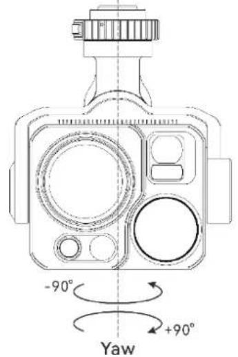

Fig 3-14 Mechanical Rotation Range of the Gimbal of the Autel Alpha Aircraft

Note
- You can control the rotation range of the gimbal pitch, ranging from -90^ to 30^ . For more setting details, see "6.5.6 Gimbal Settings" in Chapter 6.
3.7.5 Gimbal Operations
■ Remote Controller Control
- Left dial wheel: Used to adjust the gimbal pitch. Turn left to rotate the gimbal down, and turn right to rotate the gimbal up.
- Custom keys C1/C2: After setting the C1 or C2 key to "Gimbal Pitch Recenter/45°/Down", you can press the key to switch the gimbal angle.

Tip
- For the control operations of the remote controller, see "4.1.1 Remote Controller Components" and "4.11.1 Custom Keys C1 and C2" in Chapter 4.
■ Autel Enterprise App Control
For the gimbal control operations in the Autel Enterprise App, see "6.8.1 Camera Function Area" in Chapter 6.

Warning
- When the aircraft is not in use, especially when the aircraft is being transferred or stored, be sure to use the protective cover of the gimbal to fix the gimbal, so as to avoid damage to the gimbal camera due to accidental rotation or bumping.
- Please remove the protective cover of the gimbal before turning on the gimbal, otherwise, it may cause damage to the gimbal motor and circuit.
- When turning on the power switch of the aircraft, the gimbal will automatically rotate to perform self-check and calibration, please make sure there is no object near the gimbal to hinder its movement.
3.7.6 Replacing The Gimbal
The Autel Alpha aircraft has a removable gimbal design, allowing you to easily replace the gimbal to meet your flight needs in various scenarios.

Important
- Please follow the instructions below to replace the gimbal, as improper replacement may cause damage to the gimbal or poor contact with the gimbal interface.
- Do not replace the gimbal frequently. The gimbal connector is a precision element, and frequent plugging and unplugging may result in poor contact between the aircraft and the gimbal.
- Please use the gimbal model specified by Autel Robotics for replacement. Incompatible gimbals may cause damage to the aircraft.

Warning
- Do not attempt to remove or mount the gimbal when it is powered on. Wait for 15 seconds after powering off the aircraft (the internal capacitor is fully discharged) before removing or mounting the gimbal.
■ Mounting the Gimbal
- Make sure the aircraft is powered off. Remove the protective covers on the gimbal interface and the aircraft's gimbal interface. Align the red dot on the gimbal lock ring with the red dot on the aircraft's gimbal interface.
- Lift the gimbal camera upward, align the gimbal interface, and insert it into the aircraft's gimbal interface, ensuring a secure connection.
- Rotate the gimbal lock ring to the direction indicated for locking "☐" on the aircraft's gimbal interface. After the gimbal camera is locked, you will hear a clicking sound at the gimbal unlock button.
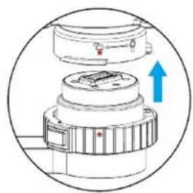
natural_image
Diagram of a mechanical device with a blue upward arrow indicating motion or force (no text or symbols present)①


natural_image
Technical line drawing of a mechanical component with flanged ends and a central hub (no text or symbols)②

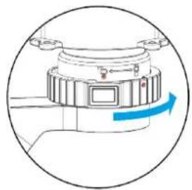
natural_image
Diagram of a mechanical component with a blue arrow indicating rotational motion (no text or symbols)③
Fig 3-15 Mounting the Gimbal
Important
- After installed the gimbal camera, you can try to rotate the gimbal lock ring in the reverse direction (do not press the gimbal unlock button). If the gimbal lock ring cannot rotate, means the gimbal is well installed.
● After installing the gimbal camera, please remove the lens cover on the gimbal camera. - Please power on the aircraft for a self-check to ensure the gimbal camera is functioning correctly. During the self-check, the gimbal camera will automatically rotate for calibration. Please make sure there are no obstacles near the gimbal camera.
■ Removing the Gimbal
- Make sure the aircraft is powered off. Hold the gimbal camera with one hand and press the gimbal unlock button with the other hand.
- Rotate the gimbal lock ring to the unlocking direction with the unlocking symbol "" on the aircraft's gimbal interface.
- After unlocking, the gimbal camera will release from the aircraft's gimbal interface.
Warning
- When removing the gimbal, please hold the gimbal camera to prevent it from falling and causing damage.

natural_image
Hand holding a mechanical component, no visible text or symbols①

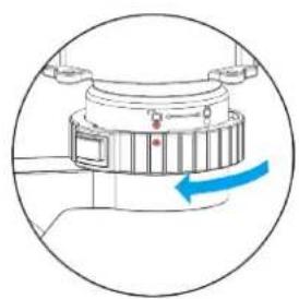
natural_image
Diagram of a mechanical component with a blue arrow indicating direction (no text or symbols present)②


natural_image
Diagram of a mechanical device with a blue arrow indicating downward motion (no text or symbols present)③
Fig 3-16 Removing the Gimbal
3.7.7 Other Functions
The DG-L35T gimbal camera supports a lens heating and defog function. When flying and shooting in environments with mist, water vapor may affect the image quality. You can improve this by tapping the "💡" icon in the tool box on the Autel Enterprise App to activate the defog function.
After enabling the defog function, the internal heating wire of the gimbal camera will heat the camera lens for physical defogging. Simultaneously, the captured images will undergo quality improvement and enhance color contrast for a better image/video output.
| Tip |
| ● For detailed introduction on operating the heating and defogging function, see "6.4 Shortcut Toolbar" in Chapter 6. |
3.8 Flight Control System
The Autel Alpha aircraft achieves stable and convenient flight control through its built-in intelligent flight control system. The system supports a number of advanced functions, including auto-return, failsafe, visual positioning system, etc.
Table 3-11 Flight Control System
| Module | Description |
| IMU | A three-axis gyroscope and a three-axis accelerometer measure acceleration and angular velocity. |
| Compass | Measures the geomagnetic field and provides reference information on the aircraft heading. |
| GNSS receiver | Receives global satellite navigation signals to measure longitude, latitude, and altitude. |
| Barometer | Measures atmospheric pressure and is used to determine the altitude of the aircraft. |
| Visual Sensing System | Provides the aircraft with 720° obstacle awareness around the fuselage. |
| Millimeter Wave Radar | Provides the aircraft with all-day and all-weather obstacle avoidance capabilities. |
3.8.1 Flight Status
Depending on the availability of GNSS signals and flight conditions, the aircraft can automatically switch between three modes.
Table 3-12 Flight Status
| Mode | Description |
| GNSS Mode | GNSS mode is activated when the aircraft detects an appropriate GNSS signal. In GNSS mode, if the obstacle avoidance system is turned on, the system will provide auxiliary information to more accurately locate and avoid obstacles, provide stable and smooth flight control, and support auto-return, failsafe, and other safety functions. |
| Visual Positioning Mode | When the aircraft is in the visual positioning mode, and the GNSS signal detected is not strong enough to activate GNSS mode, and it meets certain environmental and altitude requirements (ensure that the surrounding environment is well-lit, the ground texture is clear, and the altitude of the aircraft must be within the observation range of the visual sensing system), the visual positioning mode will be activated. |
| ATTI Mode (Attitude Mode) | When there is no GNSS signal and the environment and altitude cannot meet the requirements of the visual sensing system, that is, when there is no GNSS signal and visual positioning failure at the same time, the ATTI mode will be activated. In this mode, the obstacle avoidance system is disabled, and the aircraft only controls the altitude through the barometer. |

Warning
- If you have not fully mastered the flight control of the aircraft and the aircraft is in ATTI mode, please do not take off rashly.
3.8.2 Flight Modes
The aircraft has varying flight performance in different flight modes. You can set the flight mode of the aircraft in the Autel Enterprise App. For more information, see "6.3 Status Notification Bar" and "6.5.1 Flight Control Parameter Setting" in Chapter 6.
Table 3-13 Flight Modes
| Flight Modes | Description |
| Slow | Forward, backward, left, and right: 3 m/s; Ascend: 3 m/s; Descend: 3 m/s. |
| Smooth | Forward, backward, left, and right: 10 m/s; Ascend: 5 m/s; Descend: 5 m/s. |
| Standard | Forward and backward: 15 m/s; Left and right: 10 m/s; Ascend: 6 m/s; Descend: 6 m/s. |
Ludicrous
Forward: 25 m/s; Backward: 18 m/s; Left and right: 20 m/s; Ascend: 15 m/s; Descend: 10 m/s.

Warning
- If you have not fully mastered the flight control of the aircraft, it is not recommended for you to switch to Ludicrous mode.
- When flying close to the ground, it is recommended to switch to Slow mode for safety.
- When switching to Ludicrous mode, the obstacle avoidance function of the aircraft will become unavailable, and the aircraft will not automatically avoid surrounding obstacles during flight. Please pay attention to the surrounding environment when using it, and manually control the aircraft to avoid obstacles.
- When switching to Ludicrous mode, its flight speed is greatly improved compared with Standard mode, so the braking distance in this mode will be correspondingly extended. You should maintain a braking distance of at least 50 meters when operating the aircraft in this mode to ensure personal and flight safety.
3.8.3 Intelligent Flight Function
■ Accurate Landing
The accurate landing function uses the downward binocular visual sensing system of the aircraft to record the information at its take-off point. When the aircraft is returning to the home point or landing, vision algorithms are used to calculate the distance between the aircraft and the take-off point in real time so as to make sure that the aircraft successfully lands at the take-off point.
■ Landing Protection
The landing protection function uses the downward visual sensing system of the aircraft to create a depth image, then calculate the flatness and angle of the depth image to detect whether the surface is flat enough for a safe landing.
■ Intelligent Obstacle Avoidance
The intelligent obstacle avoidance function uses the combined observation results of the visual sensing system and the forward millimeter-wave radar sensing system of the aircraft to calculate the optimal flight path, achieving obstacle avoidance in multiple directions.
3.8.4 Hot Swap Battery
The Autel Alpha aircraft supports hot-swappable batteries, which allows you to replace smart batteries without powering off the aircraft, thus avoiding waiting for rebooting.

Important
- The detailed introduction for battery replacement please see "5.3.1 Installing/Removing the Smart Battery" in Chapter 5.
- It is recommended to label the batteries for better management. The two batteries used for replacement should have similar power levels and cycle counts to ensure consistent battery performance.
3.9 Installing the microSD Card
The aircraft comes with a 128 GB microSD card (pre-installed in the microSD card slot of the payload at the factory). If you want to replace it with a higher-capacity microSD card, please follow the steps below.

Fig 3-17 Installing the microSD Card
| Tip |
| ● If you plan to shoot high-definition videos, we recommend using a Class 10, UHS-3, or higher microSD card. |
| ⚠ Warning |
| ● To prevent data loss, please turn off the aircraft before removing the microSD card.● After installing the microSD card, close the rubber protective cover over the interface area promptly to avoid affecting the protective performance of the gimbal. |
3.10 Connecting to PC/MAC
To transfer photos and videos to a PC, MAC, or other devices, please use a data cable to connect to the device through the USB-C interface of the gimbal.

natural_image
Line drawing of a quadcopter drone connected to a laptop via cable (no text or symbols)Fig 3-18 Connect to PC/MAC via Gimbal USB-C Interface

Warning
- When connecting the gimbal camera to a PC/Mac, please do not operate the gimbal camera through the remote controller to prevent damage.
- The gimbal camera does not support PC/Mac connection when it is not powered on.
3.11 Extension Interface
The left and right sides of the aircraft are provided with expansion interfaces (PSDK interface, OSDK interface) based on the form of USB-C interface, which can provide the aircraft with additional functional expansion devices, such as searchlight, shouting device, upper gimbal and so on.

Important
- Do not plug a device (like charger) that uses other USB-C interface standards into the extension interface, as it may damage the aircraft.
- Before flight, make sure that the external mount is securely connected to the aircraft and the fixing screws on both sides are tightened.
● Pay attention to the battery level of the aircraft during flight. Mount operations consume the battery power of the aircraft, which will reduce the flight time of the aircraft.
● After removing an external mount from the aircraft, be sure to close the rubber protective cover over the interface area. Otherwise, the protective performance of the aircraft will be affected.

Note
- For external mounts, see "3.2 Aircraft Components" in this chapter for more details.

Tip
- Compatible mount list will be updated in further upgrades.
3.12 Protection Rating
Under controlled laboratory conditions, the Autel Alpha aircraft (with smart batteries installed) can achieve an IP55 protection rating following IEC 60529 standards. The protection rating is not permanent and may degrade due to long-term wear and tear.
- It is not recommended to fly in rainy conditions. In case of rain during the flight, abort the flight and return to a safe location promptly.
- Before flight, make sure that the battery connector, battery compartment interface, battery surface, and battery compartment surface are dry and water-free before inserting the battery into the aircraft fuselage.
- After completing the flight, wipe off the rainwater on the aircraft fuselage before folding and storing the aircraft to prevent water from entering the aircraft and affecting its protective performance.
- Make sure that the battery connector and surface are dry and water-free before charging the battery.
● Damage caused by immersion in liquid is not covered by the warranty.
The aircraft does not have an IP55 protection rating in the following conditions: - The aircraft is not installed with a battery or the battery is not properly installed.
- The rubber protective cover at the interface of the fuselage or the gimbal is not properly installed.
- There are other possible damage on the fuselage, such as shell cracks or waterproof adhesive failure.

Note
- Please strictly comply with the usage environment restrictions of the aircraft. Using the aircraft beyond specified conditions may lead to aircraft damage or safety incidents.
3.13 Noise
The Autel Alpha aircraft will generate a certain level of noise during operation. You should understand local noise pollution prevention regulations in advance and set an appropriate flight altitude or safe distance to ensure that it does not disturb other individuals, groups, or organizations.
■ A-weighted sound power level
The Autel Alpha aircraft has passed sound power test conducted by relevant third-party testing organizations with qualification. The results comply with the regulations concerning unmanned aerial vehicles in the European Union.
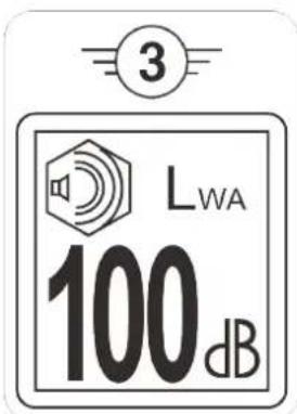
Fig 3-19 A-weighted sound power level of the Autel Alpha aircraft
■ A-weighted sound pressure level
Measurement results for the Autel Alpha aircraft, in accordance with the requirements of GB 42590-2023 in Chinese Mainland, are provided below:
Table 3-14 Noise Measurements Results (normalized to 1 m from the aircraft)
| Observation Points | Hover | Fly (1 m/s) |
| Ground Measure Point (Below) | 80.4dB 81.3dB | |
| Side Measure Point (Horizontal Plane) | 78.0dB 75.9dB |
Note: The measurement environment is an outdoor cement ground.

Tip
- Before flight, please make sure to verify the noise restrictions in the flying area in advance to avoid any violation of local regulations regarding aircraft noise.
3.14 Autel SkyLink Image Transmission Function
The Autel Alpha aircraft is equipped with Autel SkyLink 3.0 image transmission technology and has 4 image transmission antennas, with 2 channels of transmitting signals and 4 channels of receiving signals, so that the communication distance between the aircraft and the remote controller can reach up to 15 kilometers.
- It supports adaptive frequency hopping transmission of multiple frequency bands, selects the optimal channel according to the electromagnetic interference situation, and has strong anti-interference ability.
- The quality of real-time transmission reaches 1080p/30fps, and it has a high transmission bit rate of 64Mbps and low-latency transmission characteristics.
● Data link transmission uses AES-128 encryption, and data storage uses AES-256 encryption to ensure end-to-end data security.

Note
- The transmission data is based on the remote controller and comes from test data, and the test environment and conditions are different, and the data may be different.
- The transmission range is for reference only. During use, please pay close attention to the quality of the image transmission signal. When the image transmission signal is weak, reduce the flight radius in a timely manner. For more information, see "6.3 Status Notification Bar" in Chapter 6.
- Please note that the maximum communication distance of the included remote controller is 15 kilometers. To achieve a 20-kilometer communication distance with the aircraft, a ground device with stronger communication capabilities is required.
■ Information Of Communication Frequency Bands for Aircraft
The communication frequency bands of the Autel Alpha comply with regulatory requirements worldwide. The relevant certified frequency bands are listed in the table below.
In actual use, after power-on and paired the aircraft and the remote controller, the Autel Enterprise App in the remote controller will automatically determine the location based on the GNSS information received by the aircraft. It will then automatically select the radio communication frequency band that complies with local regulations for the specific country or region.

Tip
- After the aircraft is paired with the remote controller, the frequency bands between them will be automatically controlled by the Autel Enterprise App based on the geographical information of the aircraft. This is to ensure compliance with local regulations regarding frequency bands.
- Users can also manually select a legal image transmission frequency band. For detailed instructions, see "6.5.4 Image Transmission Settings" in Chapter 6.
- Before flight, please ensure that the aircraft receives a strong GNSS signal after powering on. This allows the Autel Enterprise App to receive the proper communication frequency band.
- When users adopt visual positioning mode (such as in scenarios without GNSS signals), the wireless communication frequency band between the aircraft and remote controller will default to the band used in the previous flight. In this case, it is advisable to power on the aircraft in an area with a strong GNSS signal, then start flight in the actual operational area.
Table 3-15 Global Certified Frequency Bands (Image Transmission)
| Operating Frequency | Details Bandwidth | Certified Countries & Regions | |
| 900M 902 - 928MHz | ■ BW=1.4MHz ■ BW=10MHz ■ BW=20MHz | ■ USA ■ Canada | |
| 2.4G | 2400 - 2476MHz | ■ BW=1.4MHz | ■ Chinese |
- Some countries and regions have strict restrictions on the use of radio communication frequency bands. It is crucial to use them legally, and any modification of communication modules is strictly prohibited.
- In Germany there's specific requirements for the 5.1 GHz frequency band. Unmanned aerial systems are only allowed to use the frequency within the range of 5170MHz to 5250MHz.
- If flying in any countries not listed in the above table, please consult the local communication management authorities to ensure that the aircraft communication frequency bands comply with local regulatory requirements.
- UAS will automatically match the legal frequency band based on GNSS positioning, so users can use it with confidence.
■ Remote Control Devices
The aircraft supports pairing with the Remote Controller for remote communication control over the aircraft.
Table 3-16 Remote Control Device Support List
| Control Device Information | Autel Smart Controller V3 |
| Part Number (EAN) | 6924991129011 |
| Part Number (UPC) | 889520209014 |
| Manufacturer | Autel Robotics |
| Control Software | Autel Enterprise App |
| Software Version Requirement | V1.0.0.0 or higher |
| Supplementary Information | Standard configuration |

Tip
- Autel Smart Controller V3 is a standard accessory in the aircraft package, and we also provide retail package to choose separately.
- We offer multiple retail versions for Autel Smart Controller V3. Only the remote controller installed with the Autel Enterprise App supports the control of Autel Alpha aircraft. Please consult Autel Robotics when making a purchase.
- When using the above devices to remotely control the aircraft, make sure that the control software version meets the above requirements.
Chapter 4 Remote Controller
4.1 Introduction
The Autel Smart Controller V3 is installed with the Autel Enterprise App by default, allowing you to operate and set the aircraft and the gimbal camera and transmit high-definition videos from the gimbal camera in real time. It offers a maximum communication distance of 15 kilometers.

Note
- The maximum communication distance of the Autel Smart Controller V3 is measured under unblocked and interference-free conditions and is for references only.
- It supports adaptive frequency hopping transmission, selects the optimal channel according to the electromagnetic interference situation, and has strong anti-interference ability.
- Data link transmission uses AES-128 encryption, and data storage uses AES-256 encryption to ensure end-to-end data security.
4.1.1 Remote Controller Components

Fig 4-1 Remote Controller Top-Down View
Table 4-1 Remote Controller Top-Down View Details
| No. | name | Description |
| 1 | Left Command Stick | Controls the state of motion of the aircraft. The default stick mode is Mode 2. In this mode, you can use the stick to control the ascent, descent, and heading of the aircraft. You can set the stick mode in the Autel Enterprise App. For more information, see “6.5.3 RC Settings” in Chapter 6. |
| 2 | Left Dial Wheel | Turn the dial wheel to adjust the gimbal pitch. |
| 3 | Video Recording Button | Press the button to start/end recording videos. |
| 4 Key C1 | Use the Autel Enterprise App to customize the key function. For more information, see “6.5.3 RC Settings” in Chapter 6. | |
| 5 Air Outlet | For heat dissipation of the remote controller. When using it, please pay attention to whether there are foreign objects blocking the air outlet. | |
| 6 HDMI Interface | Outputs the live view of the remote controller to a supported display device. | |
| 7 | USB-C Interface | Used for remote controller charging or device debugging. |
| 8 USB-A Interface | Connects to an expandable 4G/5G module or external USB device for data transmission. | |
| 9 Power button | Long press for 3s to turn on/off the remote controller. When the remote controller is on, quickly press the power button to switch between Screen On and Screen Off. | |
| 10 Key C2 | Use the Autel Enterprise App to customize the key function. For more information, see “6.5.3 RC Settings” in Chapter 6. | |
| 11 | Shooting Button | Press the button to take a photo. |
| 12 | Right Dial Wheel | Turn the dial wheel to adjust the zoom factor of the camera. |
| 13 Right Stick | Controls the state of motion of the aircraft. The default stick mode is Mode 2. In this mode, you can use the stick to control the translation of the aircraft in four directions: front/back/left/right. You can set the stick mode in the Autel Enterprise App. For more information, see “6.5.3 RC Settings” in Chapter 6. | |
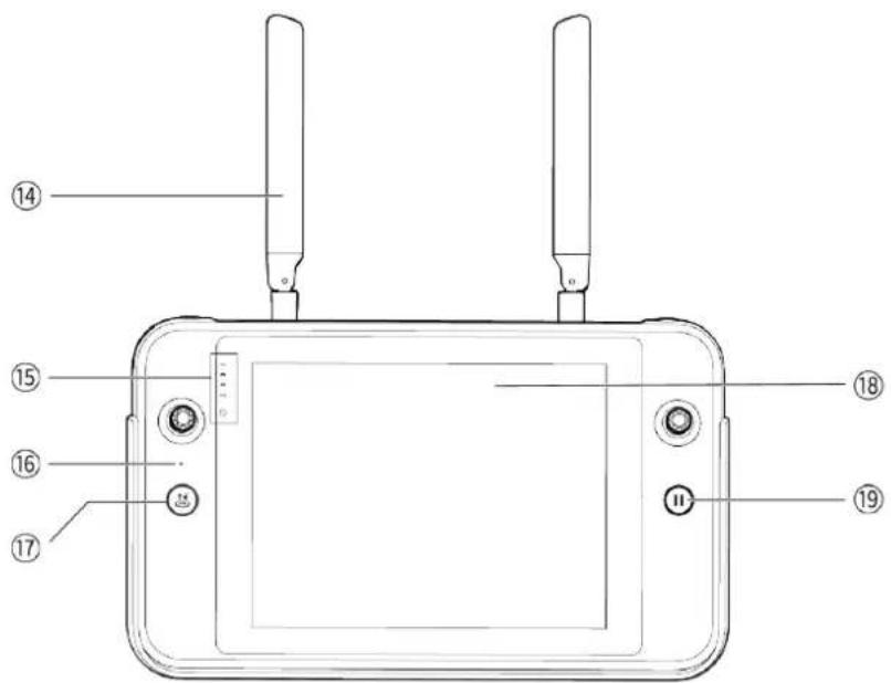
Fig 4-2 Remote Controller Front View
Table 4-2 Remote Controller Front View Details
| No. | name | Description |
| 14 | Antenna | Transmits the control signals of the remote controller and receives the image transmission information of the aircraft. |
| 15 | Battery Level Indicator | Displays the remaining battery level of the remote controller. |
| 16 | Audio Input | Receives information from an external audio source near the remote controller. |
| 17 | Take-off/Return-to-Home Button | When the aircraft is turned on but not taking off, press and hold the button for 2 seconds, and the aircraft will take off and hover at an altitude of 1.5 meters above the ground.When the aircraft is flying, press and hold the button for 2 seconds, and the aircraft will automatically begin the return-to-home process. |
| 18 | Display | Displays real-time image transmission views. with 2048×1536 resolution. Touch operation is supported. |
| 19 | Pause Button | When the aircraft is in autonomous flight mode, short press this button to control the aircraft to suspend autonomous flight and hover in place or resume autonomous flight; press and hold this button for 2 seconds to exit the autonomous flight. |

Fig 4-3 Remote Controller Rear View
Table 4-3 Remote Controller Rear View Details
| No. | name | Description |
| 20 | Speaker | Plays sound to indicate the status of the aircraft. |
| 21 Protective Cover | Optional accessory. Used to prevent external damage such as collision and abrasion of the remote controller. | |
| 22 | Lower Hook | Used to connect and fix the remote controller strap. |
| 23 | Standard 1/4 interface | Used for attaching tripods. |
| 24 Air Inlet | Used for heat dissipation of the remote controller. Please pay attention to whether there are foreign objects blocking the air inlet when using it. | |
| 25 | Command Stick Storage Slot | Used to store left and right sticks. |
4.1.2 Communication Frequency Bands
The communication frequency bands of Autel Smart Controller V3 comply with regulatory requirements worldwide. Please refer to the table below for the relevant certified frequency bands.

Tip
- After the aircraft is paired with the remote controller, the frequency bands between them will be automatically controlled by the Autel Enterprise App based on the geographical information of the aircraft. This is to ensure compliance with local regulations regarding frequency bands.
- Users can also manually select a legal image transmission frequency band. For detailed instructions, see "6.5.4 Image Transmission Settings" in Chapter 6.
- Before flight, please ensure that the aircraft receives a strong GNSS signal after powering on. This allows the Autel Enterprise App to receive the proper communication frequency band.
- When users adopt visual positioning mode (such as in scenarios without GNSS signals), the wireless communication frequency band between the aircraft and remote controller will default to the band used in the previous flight. In this case, it is advisable to power on the aircraft in an area with a strong GNSS signal, then start flight in the actual operational area.
Table 4-4 Global Certified Frequency Bands (Image Transmission)
| Operating Frequency | Details Bandwidth | Certified Countries & Regions | |
| 900M 902 - 928MHz | ■ BW=1.4MHz ■ BW=10MHz ■ BW=20MHz | ■ USA ■ Canada | |
| 2.4G 2400 - 2476MHz | ■ BW=1.4MHz ■ BW=10MHz ■ BW=20MHz | ■ Chinese Mainland | |
| 2.4G 2400 - 2483.5MHz | ■ BW=1.4MHz ■ BW=10MHz ■ BW=20MHz | ■ Taiwan, China ■ USA ■ Canada ■ EU ■ UK (UKCA) ■ Australia ■ Korea ■ Japan | |
| 5.7G 5650 - 5755MHz | ■ BW=1.4MHz ■ BW=10MHz ■ BW=20MHz | ■ Japan | |
| 5.8G 5725-5829MHz | ■ BW=1.4MHz ■ BW=10MHz ■ BW=20MHz | ■ Chinese Mainland | |
| 5.8G 5725 - 5850MHz | ■ BW=1.4MHz ■ BW=10MHz ■ BW=20MHz | ■ Taiwan, China ■ USA ■ Canada |
EU
■ UK (UKCA)
■ Australia
Korea
Table 4-5 Global Certified Frequency Bands (Wi-Fi)
| Operating Frequency Details | Certified Countries & Regions | |
| 2.4G(2400 - 2476MHz) | 802.11b/g/n ■ Chinese Mainland | |
| 2.4G(2400 - 2483.5 MHz) | 802.11b/g/n | ■ Taiwan, China■ USA■ Canada■ EU■ UK (UKCA)■ Australia■ Korea■ Japan |
| 5.1G(5150 - 5250 MHz) | 802.11a/n/ac ■ Japan | |
| 5.8G(5725 - 5850 MHz) | 802.11a/n/ac ■ Chinese Mainland | |
| 5.8G(5725 - 5850 MHz) | 802.11a/n/ac | ■ Taiwan, China■ USA■ Canada■ EU■ UK■ Australia■ Korea |

Note
- Some countries and regions have strict restrictions on the use of radio communication frequency bands. It is crucial to use them legally, and any modification of communication modules is strictly prohibited.
- If flying in any countries not listed in the above table, please consult the local communication management authorities to ensure that the aircraft communication frequency bands comply with local regulatory requirements.
- UAS will automatically match the legal frequency band based on GNSS positioning, so users can use it with confidence.
4.2 Installing the Remote Controller Lanyard

Tip
- The remote controller lanyard is an optional accessory. You can choose whether to install it as required.
- When holding the remote controller for a long time during flight operations, we recommend that you install the remote controller lanyard to effectively reduce the pressure on your hands.
■ Steps
- Clip the two metal clips on the lanyard to the narrow positions on both sides of the metal handle at the back of the controller.
- Open the metal button of the lanyard, bypass the lower hook at the bottom of the back of the controller, and then fasten the metal button.
- Wear the lanyard around your neck, as shown in the figure below, and adjust it to a suitable length.

natural_image
Line drawings of a medical device and its corresponding body frame, showing internal components and wiring (no text or symbols)Fig 4-4 Install the Remote Controller Lanyard (As Required)
4.3 Installing/Storing Command Sticks
The Autel Smart Controller V3 features removable command sticks, which effectively reduce storage space and enable easy carrying and transportation.
■ Installing command sticks
There is a command stick storage slot above the mental handle at the back of the controller. Rotate counterclockwise to remove the two command sticks and then rotate them clockwise to install them separately on the remote controller.
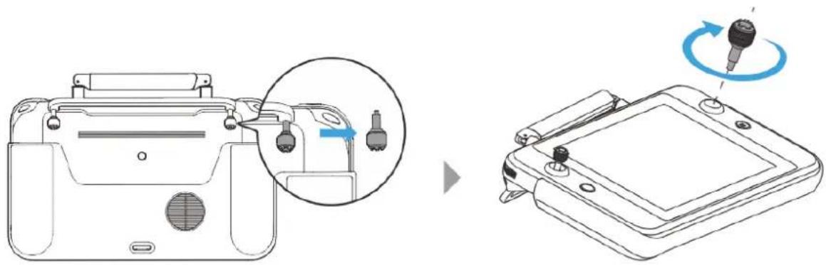
natural_image
Diagram showing a device's internal components and a close-up of its internal structure, with no visible text or symbols.Fig 4-5 Installing command sticks
■ Storing Command sticks
Simply follow the reverse steps of the above operation.

Tip
- When the command sticks are not in use (such as during transportation and temporary aircraft standby), we recommend that you remove and store them on the metal handle. This can prevent you from accidentally touching the command sticks, causing damage to the sticks or unintended startup of the aircraft.
4.4 Turning the Remote Controller On/Off
■ Turning the Remote Controller On
Press and hold the power button at the top of the remote controller for 3 seconds until the controller emits a "beep" sound to turn it on.
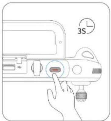
Fig 4-6 Turning the Remote Controller On

Tip
- When using a brand-new remote controller for the first time, please follow the on-screen instructions to complete the relevant setup.
■ Turning the Remote Controller Off
When the remote controller is on, press and hold the power button at the top of the remote controller until the "Off" or "Restart" icon appears at the top of the controller's screen. Tapping the "Off" icon will turn off the remote controller. Tapping the "Restart" icon will restart the remote controller.
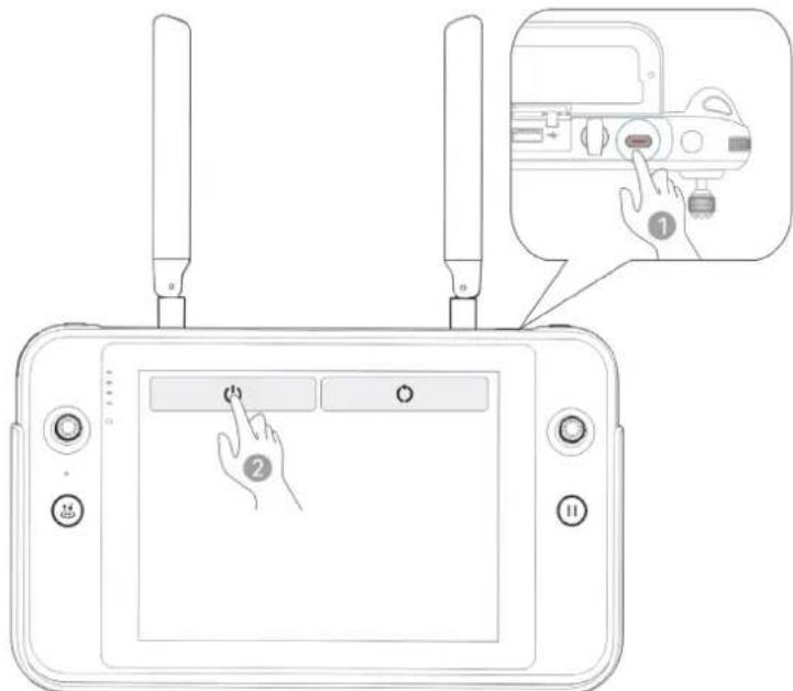
Fig 4-7 Turning the Remote Controller Off

Tip
- When the remote controller is on, you can press and hold the power button at the top of the remote controller for 6 seconds to forcibly turn it off.
4.5 Checking the Battery Level of the Remote Controller
When the remote controller is off, short press the power button of the remote controller for 1 second, and the battery level indicator will display the battery level of the remote controller.

Fig 4-8 Checking the Battery Level of the Remote Controller
Table 4-6 Battery Remaining
| Power Display | Definition | Power Display | Definition |
 | 1 light always on: 0%-25% power |  | 2 lights always on: 25%-50% power |
 | 3 lights always on: 50%-75% power |  | 4 lights always on: 75%-100% power |

Tip
When the remote controller is on, you can check the current battery level of the remote controller in the following ways:
- Check it on the top status bar of the Autel Enterprise App.
- Check it on the system status notification bar of the remote controller. In this case, you need to enable "Battery Percentage" in the "Battery" of the system settings in advance.
- Go to the system settings of the remote controller and check the current battery level of the controller in "Battery".
4.6 Charging the Remote Controller
Connect the output end of the official remote controller charger to the USB-C interface of the remote controller by using a USB-C to USB-A (USB-C to USB-C) data cable and connect the plug of the charger to an AC power supply (100-240 V\~ 50/60 Hz).
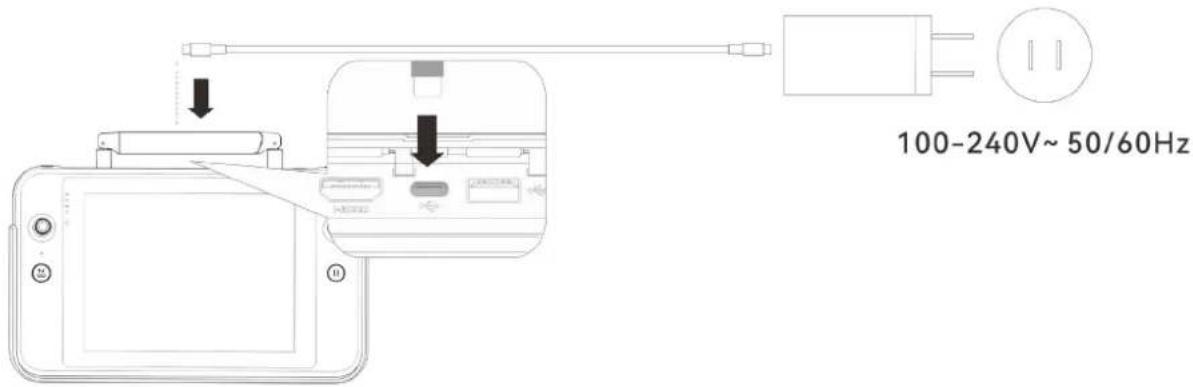
Fig 4-9 Use the remote controller charger to charge the remote controller
| Warning |
| Please use the official charger provided by Autel Robotics to charge the remote controller. Using third-party chargers may damage the battery of the remote controller.After charging is complete, please disconnect the remote controller from the charging device promptly. |
| Note |
| It is recommended to fully charge the remote controller battery before the aircraft takes off.Generally, it takes about 120 minutes to fully charge the aircraft battery, but the charging time is related to the remaining battery level. |
4.7 Adjusting the Antenna Position of the Remote Controller
During flight, please extend the antenna of the remote controller and adjust it to an appropriate position. The strength of the signal received by the antenna varies depending on its position. When the angle between the antenna and the back of the remote controller is 180^ or 270^ , and the plane of the antenna faces the aircraft, the signal quality between the remote controller and the aircraft can reach its best state.
| Important |
| ● When you operate the aircraft, make sure that the aircraft is in the place for the best communications. |
- Do not use other communication devices of the same frequency band at the same time to prevent interference with the signals of the remote controller.
- During flight, if there is a poor image transmission signal between the aircraft and the remote controller, the remote controller will provide a prompt. Please adjust the antenna orientation according to the prompt to ensure that the aircraft is in the optimal data transmission range.
- Please make sure that the antenna of the remote controller is securely fastened. If the antenna becomes loose, please rotate the antenna clockwise until it is firmly fastened.

Fig 4-10 Extend the antenna
4.8 Remote Controller System Interfaces
4.8.1 Remote Controller Main Interface
After the remote controller is turned on, it enters the main interface of the Autel Enterprise App by default.
In the main interface of the Autel Enterprise App, slide down from the top of the touch screen or slide up from the bottom of the touch screen to display the system status notification bar and navigation keys, and tap the "Home" button or the "Back" button to enter the "Remote Controller Main Interface". Swipe left and right on the "Remote Controller Main Interface" to switch between different screens, and enter other applications as needed.
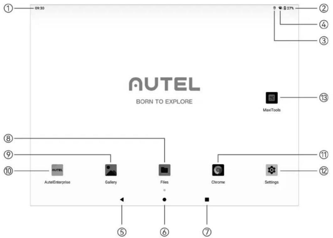
flowchart
graph TD
    A["09:30"] --> B["Autel Enterprise"]
    A --> C["Gallery"]
    A --> D["Files"]
    A --> E["Chrome"]
    A --> F["Settings"]
    G["27%"] --> H["MaxTools"]
    I["②"] --> H
    J["④"] --> H
    K["③"] --> H
    L["⑧"] --> M["⑨"]
    N["⑩"] --> O["⑪"]
    P["⑤"] --> Q["⑥"]
    R["⑦"] --> S["⑦"]
Fig 4-11 Remote Controller Main Interface
Table 4-7 Remote Controller Main Interface Details
| No. | Name Description | |
| 1 | Time | Indicates the current system time. |
| 2 | Battery Status | Indicates the current battery status of the remote controller. |
| 3 | Wi-Fi Status | Indicates that Wi-Fi is currently connected. If not connected, the icon is not displayed.You can quickly turn on or off the connection to Wi-Fi by sliding down from anywhere on the "Remote Controller Interface" to enter the "Shortcut Menu". |
| 4 | Location Info | Indicates that location information is currently enabled. If not enabled, the icon is not displayed.You can tap "Settings" to enter the "Location Information" interface to quickly turn on or off location information. |
| 5 | Back Button | Tap the button to return to the previous page. |
| 6 | Home Button | Tap the button to jump to the "Remote Controller Main Interface". |
| 7 | "Recent apps" Button | Tap the button to view all background programs currently running and take screenshots.Press and hold the application to be closed and slide up to close the application.Select the interface where you want to take a screenshot, and tap the "Screenshot" button to print, transfer via Bluetooth, or edit the screenshot. |
| 8 Files | The app is installed in the system by default. Tap it to manage the files saved in the current system. | |
| 9 Gallery | The app is installed in the system by default. Tap it to view the images saved by the current system. | |
| 10 Autel Enterprise | Flight software. The Autel Enterprise App starts by default when the remote controller is turned on. For more information, see “Chapter 6 Autel Enterprise App”. | |
| 11 Chrome | Google Chrome. The app is installed in the system by default. When the remote controller is connected to the Internet, you can use it to browse web pages and access Internet resources. | |
| 12 Settings | The system settings app of the remote controller. Tap it to enter the settings function, and you can set the network, Bluetooth, applications and notifications, battery, display, sound, storage, location information, security, language, gestures, date and time, device Name, etc. | |
| 13 Maxitools | The app is installed in the system by default. It supports the log function and can restore factory settings. | |

Tip
- The remote controller supports the installation of third-party Android apps, but you need to obtain the installation packages on your own.
- The remote controller has a screen aspect ratio of 4:3, and some third-party app interfaces may encounter compatibility issues.
Table 4-8 List of Pre-installed Apps on the Remote Controller
| No. | Pre-installed App | Device Compatibility | Software Version | Operating System Version |
| 1 | Files | √ | 11 | Android 11 |
| 2 | Gallery | √ | 1.1.40030 | Android 11 |
| 3 | Autel Enterprise | √ | 1.2.18 | Android 11 |
| 4 | Chrome | √ | 68.0.3440.70 | Android 11 |
| 5 | Settings | √ | 11 | Android 11 |
| 6 | Maxitools | √ | 2.45 | Android 11 |
| 7 | Google Pinyin Input | √ 4.5.2.193126728-arm64-v8a Android 11 | ||
| 8 | Android Keyboard (AOSP) | √ 11 Android 11 | ||

Tip
- Please be aware that the factory version of the Autel Enterprise App may vary depending on subsequent function upgrades.
4.8.2 Shortcut Menu
Slide down from anywhere on the "Remote Controller Interface", or slide down from the top of the screen in any app to display the system status notification bar, and then slide down again to bring up the "Shortcut Menu".
In the "Shortcut Menu", you can quickly set Wi-Fi, Bluetooth, screenshot, screen recording, airplane mode, screen brightness, and remote controller sound.

Fig 4-12 Shortcut Menu
Table 4-9 Shortcut Menu Details
| No. | name | Description |
| 1 | Notification Center | Displays system or app notifications. |
| 2 Time and Date | Displays the current system time, date, and week of the remote controller. | |
| Wi-Fi | Tap the “💡” icon to enable or disable the Wi-Fi function. Long press it to enter WLAN settings and select the wireless network to be connected. | |
| Bluetooth | Tap the “💡” icon to enable or disable the Bluetooth function. Long press it to enter the Bluetooth settings and select the Bluetooth to be connected. | |
| 3 | Screenshot | Tap the “💡” icon to use the screenshot function, which will capture the current screen (hide the Shortcut Menu to take a screenshot). |
| Screen Recor.. Start | After tapping on the “💡” icon, a dialog box will pop up, where you can choose whether to enable the functions of recording audio and displaying the touch screen position, and then tap the "Start" button, wait for 3 seconds, and start screen recording. Tap the icon again or tap "Screen Recorder" to turn off screen recording. | |
| Airplane mode | Tap the “💡” icon to turn on or off the airplane mode, that is, to turn on or turn off the Wi-Fi and Bluetooth functions at the same time. | |
| 4 | Screen Brightness Adjustment | Drag the slider to adjust the screen brightness. |
| 5 | Volume Adjustment | Drag the slider to adjust the media volume. |
4.9 Frequency Pairing With the Remote Controller
4.9.1 Using the Autel Enterprise App
Only after the remote controller and the aircraft are paired can you operate the aircraft using the remote controller.
Table 4-10 Frequency Pairing Process in the Autel Enterprise App
| Step | Operation | Diagram |
| 1 | Turn on the remote controller and the aircraft.After entering the main interface of the Autel Enterprise App, tap “ 📄 on the upper-right corner, tap " 🔺 ", select “ 🔺”, and then tap "Connect to aircraft". |  |
| 2 | After a dialog box pops up, double-click on the smart battery power button on the aircraft to complete the frequency pairing process with the remote controller. |  |

Note
- The aircraft included in the aircraft kit is paired with the remote controller provided in the kit at the factory. No pairing is required after the aircraft is powered on. Normally, after completing the aircraft activation process, you can directly use the remote controller to operate the aircraft.
- If the aircraft and the remote controller become unpaired due to other reasons, please follow the above steps to pair the aircraft with the remote controller again.

Important
- When pairing, please keep the remote controller and the aircraft close together, at most 50 cm apart.
4.9.2 Using Combination Keys (For Forced Frequency Pairing)
If the remote controller is turned off, you can perform forced frequency pairing. The process is as follows:
- Press and hold the power button and the take-off/return-to-home button of the remote controller at the same time until the battery level indicators of the remote controller blink quickly, which indicates that the remote controller has entered the forced frequency pairing state.
- Make sure that the aircraft is turned on. Double-click on the power button of the aircraft, and the front and rear arm lights of the aircraft will turn green and blink quickly.
- When the front and rear arm lights of the aircraft and the battery level indicator of the remote controller stop blinking, it indicates that the frequency pairing is successfully done.
4.10 Selecting Stick Mode
4.10.1 Stick Modes
When using the remote controller to operate the aircraft, you need to know the current stick mode of the remote controller and fly with caution.
Three stick modes are available, that is, Mode 1, Mode 2 (default), and Mode 3.
■ Mode 1

flowchart
graph TD
    A["Device"] --> B{Control Signals}
    B --> C["Drone"]
    C --> D["Sensor Input"]
    D --> E["Feedback Loop"]
    E --> F["Sensor Output"]
    F --> G["Drone"]
    G --> H["Sensor Input"]
    H --> I["Feedback Loop"]
    I --> J["Sensor Output"]
Fig 4-13 Mode 1
Table 4-11 Mode 1 Details
| Stick | Move Up/Down | Move Left/Right |
| Left Command Stick | Controls the forward and backward movement of the aircraft | Controls the heading of the aircraft |
| Right Stick | Controls the ascent and descent of the aircraft | Controls the left or right movement of the aircraft |
■ Mode 2

flowchart
graph TD
    A["Drone"] -->|Signal| B["Smart Phone"]
    B --> C{Signal}
    C -->|Control| D["Smart Phone"]
    D --> E["Drone"]
    E --> F["Smart Phone"]
    F --> G{Signal}
    G -->|Control| H["Smart Phone"]
    H --> I["Drone"]
    I --> J["Smart Phone"]
    J --> K{Signal}
    K -->|Control| L["Smart Phone"]
    L --> M["Drone"]
    M --> N["Smart Phone"]
    N --> O{Signal}
    O -->|Control| P["Smart Phone"]
    P --> Q["Drone"]
    Q --> R["Smart Phone"]
    R --> S{Signal}
    S -->|Control| T["Smart Phone"]
    T --> U["Drone"]
    U --> V["Smart Phone"]
Fig 4-14 Mode 2
Table 4-12 Mode 2 Details
| Stick | Move Up/Down | Move Left/Right |
| Left Command Stick | Controls the ascent and descent of the aircraft | Controls the heading of the aircraft |
| Right Stick | Controls the forward and backward movement of the aircraft | Controls the left or right movement of the aircraft |
■ Mode 3

flowchart
graph TD
    A["Drone"] --> B["Control Device"]
    B --> C{Signal}
    C -->|Yes| D["Output Signal"]
    C -->|No| E["Feedback Loop"]
    E --> F["Drone"]
    F --> G["Control Device"]
    G --> H{Signal}
    H -->|Yes| I["Output Signal"]
    H -->|No| J["Feedback Loop"]
    J --> K["Drone"]
    K --> L["Control Device"]
    L --> M{Signal}
    M -->|Yes| N["Output Signal"]
    M -->|No| O["Feedback Loop"]
Fig 4-15 Mode 3
Table 4-13 Mode 3 Details
| Stick | Move Up/Down | Move Left/Right |
| Left Command Stick | Controls the forward and backward movement of the aircraft | Controls the left or right movement of the aircraft |
| Right Stick | Controls the ascent and descent of the aircraft | Controls the heading of the aircraft |

Warning
- Do not hand over the remote controller to persons who have not learned how to use the remote controller.
- If you are operating the aircraft for the first time, please keep the force gentle when moving the command sticks until you are familiar with the operation.
- The flight speed of the aircraft is proportional to the degree of the command stick movement. When there are people or obstacles near the aircraft, please do not move the stick excessively.
4.10.2 Setting Stick Mode
You can set the stick mode according to your preference. For detailed setting instructions, see "6.5.3 RC Settings" in Chapter 6. The default stick mode of the remote controller is "Mode 2".
Table 4-14 Default Control Mode (Mode 2)
| Mode 2 | Aircraft Flight Status | Control Method |
| Left Command StickMove Up or Down |  | 1. The up-and-down direction of the left stick is the throttle stick, which is used to control the vertical lift of the aircraft.2. Push the stick up, and the aircraft will rise vertically; pull the stick down, and the aircraft will descend vertically.3. When the stick is returned to the center, the altitude of the aircraft remains unchanged.4. When the aircraft takes off, please push the stick up to above the center, and the aircraft can lift off the ground. |
 | ||
| Left Command StickMove Left or Right | 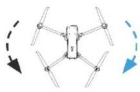 | 1. The left-and-right direction of the left stick is the yaw stick, which is used to control the heading of the aircraft.2. Push the stick to the left, and the aircraft will rotate counterclockwise; push the stick to the right, and the aircraft will rotate clockwise.3. When the stick is returned to the center, the rotational angular velocity of the aircraft is zero, and the aircraft does not rotate at this time.4. The larger the degree of the stick movement, the greater the rotational angular velocity of the aircraft. |
 | ||
| Right Stick |
Move Up or Down
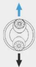

natural_image
Diagram of a drone with directional arrows indicating flight or movement (no text or symbols)Right Stick Move Left or Right

natural_image
Diagram showing a drone with two wheels and directional arrows, no text or symbols present- The up-and-down direction of the right stick is the pitch stick, which is used to control the flight of the aircraft in the forward and backward directions.
- Push the stick up, and the aircraft will tilt forward and fly towards the front of the nose; pull the stick down, and the aircraft will tilt backward and fly towards the tail of the aircraft.
- When the stick is returned to the center, the aircraft remains horizontal in the forward and backward directions.
-
The larger the degree of the stick movement, the faster the flight speed of the aircraft, and the larger the tilt angle of the aircraft.
-
The left-and-right direction of the right stick is the roll stick, which is used to control the flight of the aircraft in the left and right directions.
- Push the stick to the left, and the aircraft will tilt to the left and fly to the left of the nose; pull the stick to the right, and the aircraft will tilt to the right and fly to the right of the nose.
- When the stick is returned to the center, the aircraft remains horizontal in the left and -right directions.
- The larger the degree of the stick movement, the faster the flight speed of the aircraft, and the larger the tilt angle of the aircraft.

Note
- When controlling the aircraft for landing, pull the throttle stick down to its lowest position. In this case, the aircraft will descend to an altitude of 1.2 meter above the ground, and then it will perform an assisted landing and automatically descend slowly.
4.10.3 Starting/Stopping the Aircraft Motor
Table 4-15 Start/Stop the Aircraft Motor
| Process | Stick Operation | Description | |
| Start the aircraft motor when the aircraft is powered on |  |  | Power on the aircraft, and the aircraft will automatically perform a self-check (for about 30 seconds). Then simultaneously move the left and right sticks inward or outward for 2 seconds, as shown in the figure, to start the aircraft motor. |
 |  | ||
| Stop the aircraft motor when the aircraft is landing |  | When the aircraft is in landing state, pull the throttle stick down to its lowest position, as shown in the figure, and wait for the aircraft to land until the motor stops. | |
 |  | When the aircraft is in landing state, simultaneously move the left and right sticks inward or outward, as shown in the figure, until the motor stops. | |
 |  | ||

Warning
- When taking off and landing the aircraft, stay away from people, vehicles, and other moving objects.
- The aircraft will initiate a forced landing in case of sensor anomalies or critically low battery levels.
4.11 Remote Controller Keys
4.11.1 Custom Keys C1 and C2
You can customize the functions of the C1 and C2 custom keys according to your preferences. For detailed setting instructions, see "6.5.3 RC Settings" in Chapter 6.

natural_image
Line drawing of a device rear panel with labeled ports (C1, C2) and connectors (no text or symbols beyond labels)Fig 4-16 Custom Keys C1 and C2
Table 4-16 C1 and C2 Customizable Settings
| No. | Function Description | |
| 1 | Visual Obstacle Avoidance On/Off | Press to trigger: turn on/off the visual sensing system.When this function is enabled, the aircraft will automatically hover when it detects obstacles in the field of view. |
| 2 | Gimbal Pitch Recenter/45°/Down | Press to trigger: switch the gimbal angle.➢ Gimbal Pitch Recenter: The heading angle of the gimbal returns from the current position to be consistent with the heading of the aircraft nose, and the gimbal pitch angle returns to a 0° direction from the current angle;➢ Gimbal Pitch 45°: The heading angle of the gimbal returns from the current position to be consistent with the heading of the aircraft nose, and the gimbal pitch angle returns to a 45° direction from the current angle;➢ Gimbal Pitch Down: The heading angle of the gimbal returns from the current position to be consistent with the heading of the aircraft nose, and the gimbal pitch angle rotates to a 90° direction from the current angle. |
| 3 | Map/Image Transmission | Press to trigger: switch the map/image transmission view. |
| 4 | Speed Mode | Press to trigger: switch the flight mode of the aircraft. For more information, see “3.8.2 Flight Modes” in Chapter 3. |
| Warning | ||
| ● When the speed mode of the aircraft is switched to “Ludicrous”, the visual obstacle avoidance system will be turned off. | ||
4.11.2 Take-off/Return-to-Home Button and Pause Button

Warning
● The auto-return function will only be enabled when the GNSS signal is good.
- If the obstacle avoidance system is disabled during a return flight, the aircraft will not be able to automatically avoid obstacles.
- Before using the auto-return function, you need to set the home point in advance in the Autel Enterprise App. For more information, see "6.5.1 Flight Control Parameter Setting" in Chapter 6. If the home point is not set, the aircraft will take the take-off point as the home point by default.
To manually activate the auto-return function, press and hold the take-off/return-to-home button "on the remote controller for 2 seconds until the remote controller emits a "beep" sound. Upon receiving the command, the aircraft will automatically return and land at the preset home point.
When the aircraft is in the auto-return state, the remote controller will be disabled. You can short press the pause button "⑪" until the remote controller emits a "beep" sound to pause the auto-return, or long press the pause button "⑪ for 2 seconds until the remote controller emits a "beep" sound to exit the auto-return. After pausing or exiting the auto-return, you can reactivate the remote controller for controlling the aircraft.
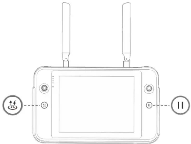
natural_image
Front view of a device with two antennas and control buttons, no text or symbols presentFig 4-17 Take-off/Return-to-Home Button and Pause Button

Tip
- When the aircraft pauses an auto-return, it will hover in place. To resume the auto-return, press the pause button “ ^11 ” again until the remote controller emits a "beep" sound.

Warning
- If the auto-return home point is not suitable for the aircraft to land (such as uneven ground and crowds), please exit the auto-return before the aircraft reaches the home point, and then manually resume control to land.
4.12 Turning On/Off the Remote Controller Prompt Sound
In some scenarios, the remote controller will send a prompt sound, such as the screen lock sound and power-on sound.

Tip
- You can access the system settings app from the main interface of the remote controller, and then drag the volume slider in "Sound" to adjust the media volume and notification volume separately.
4.13 Calibrating the Remote Controller
If the remote controller is abnormal, it is recommended to calibrate it, as shown below.
Table 4-17 Calibrating the Remote Controller
| Step | Operation | Diagram |
| 1 | Turn on the remote controller. After entering the main interface of the Autel Enterprise App, tap “☐” in the upper-right corner, tap “”, select "☐", and then tap "RC Calibration". Follow the on-screen instructions to calibrate the remote controller. |  RC CalibrationPlease do not touch the sticks before clicking the start button. Make sure to follow the instructions carefully during calibration, as failure to do so may result in a failed calibration.Start calibrating RC CalibrationPlease do not touch the sticks before clicking the start button. Make sure to follow the instructions carefully during calibration, as failure to do so may result in a failed calibration.Start calibrating |
2
Calibration of the dials and command sticks: According to the calibration guide page of the remote controller, move the left and right dial wheels and the left and right sticks according to the directions shown in the figure and hold for 1 second. At this time, a beep will be heard, and the calibration direction icon will be changed from gray to dark blue, indicating that the orientation calibration was successful.
There is no order in which directions are calibrated, until all directions are calibrated, the remote controller calibration is done.

4.14 HDMI Screen Output
The remote controller is equipped with an HDMI interface. The interface allows you to output the real-time screen of the remote controller to supported digital devices such as display screens.
Chapter 5 Smart Battery
5.1 Battery Introduction
The Autel Alpha aircraft comes standard with two MDH_10000_23700 smart batteries (hereafter referred to as smart battery) as the power battery. This battery is a rechargeable lithium-ion polymer (LiPo) battery and features high energy density and capacity. The smart battery can be charged with a DF_CHARGER.

Note
- The battery charger is included as part of the aircraft kit. You do not need to purchase it separately.

Fig 5-1 Battery Appearance
Table 5-1 Battery Appearance Details
| No. | Name | Description |
| 1 | Battery Limiting Block | When installing the smart battery into the aircraft, ensure that this side is facing up, insert the battery into the battery compartment until the battery limiting block is locked by the battery unlock lever. |
| 2 | Power Button | When battery is powered off, short power the button for 1s to check the battery level. |
| 3 | Battery Level Indicator | Used to display the current battery level of the smart battery in normal situations. |
5.2 Smart Battery Functions
The smart battery has the following functions:
■ Battery Level Display
The smart battery has a built-in battery level indicator, which shows the current battery level of the smart battery.
■ Self-heating
This function allows the smart battery to operate normally even in low-temperature environments, ensuring flight safety. For more information, see "5.3.3 Smart Battery Self-heating" in this chapter.
■ Communication
The aircraft can obtain real-time battery information, such as voltage, current, battery level, and battery temperature, through the communication interface on the smart battery.
■ Power Saving Mode
The smart battery will automatically shut down after 5 seconds of inactivity to reduce power consumption.
■ Dust and Water Resistance
When correctly installed in the aircraft, the battery has an IP43 protection rating.
■ Ultra-low Power Mode
When the smart battery is idle for 24 hours and the battery level is less than 8%, the battery BMS will enter the ultra-low power mode to reduce self-consumption. When entering ultra-low power mode, it needs to be activated by a charger before it can continue to use normally.
■ Self-discharge Protection
If the smart battery is stored in a high-temperature environment or not used for 6 days with a high battery level, the self-discharge protection will be activated. The smart battery will automatically discharge to a battery level of about 60% (by default) and the discharge process takes 2-3 days.

Tip
- Although the battery has no indication of a self-discharge cycle, you may notice that the battery is slightly warm, which is normal.
■ Sleep Mode Protection
If the smart battery has a low battery level, it will automatically enter sleep mode to prevent over-discharge. In this mode, the smart battery does not respond when the power button is pressed. To wake up the battery, you can connect it to a battery charger.
■ Charge Temperature Protection
The smart battery will stop charging when its temperature is lower than 10^ C ( 50^ F) or higher than 40^ C ( 104^ F) during charging, as charging the battery under such temperatures will damage the battery.
■ Overcurrent Protection
The smart battery will stop charging when the charging current is too high, as charging the battery with a high current can severely damage the battery.
■ Overcharge Protection
Charging will stop automatically when the smart battery is fully charged, as overcharging can severely damage the battery.
■ Balance Protection
The voltage of each battery cell in the smart battery is automatically kept balanced to protect the battery and maximize the performance of the battery.
■ Short Circuit Protection
Once a short circuit is detected, the power supply of the smart battery will be cut off to protect the battery.
■ Hot Swapping Batteries
The smart battery supports hot-swappable function. When the aircraft lands and battery replacement is needed, you can replace one fully charged battery without turning off the aircraft power and wait until the battery level indicator light turns on before replacing another battery.
■ Over-Discharge Protection
When the smart battery is installed on the aircraft and is powered on but not in use, if the battery level becomes too low, the battery will automatically disconnect power output. This feature is disabled during flight.

Warning
- Before using the smart battery, please carefully read and strictly follow the requirements in this Manual, "Battery Safety Operation Guidelines", and "Disclaimer", and those on the battery's surface sticker. The user shall undertake all consequences if he/she fails to follow the usage requirements.
5.3 Smart Battery Usage
- Please use a smart battery within the appropriate temperature range (refer to the operating temperature of the aircraft). Using it in too high or low temperatures will affect the battery's safety and lifespan and may cause spontaneous battery combustion or permanent damage to the battery.
- To ensure flight safety, the aircraft is not allowed to take off when only one single battery is installed. When the two smart batteries' power difference is greater than 12%, the Autel Enterprise App will issue a warning and restrict the aircraft from taking off.
- Do not use the aircraft in a strong electrostatic (such as thunderstorms) or electromagnetic environment. Otherwise, some functions of the smart battery may fail (e.g., abnormal battery output and power failure), resulting in serious aircraft malfunctions.
- Do not use a smart battery that has ever been dropped from the aircraft or subjected to external impacts.
- Do not use a water-soaked smart battery or immerse a smart battery in water or other liquids. Water contact inside the battery may cause corrosion, resulting in spontaneous battery combustion and even an explosion.
-
Do not use a smart battery that emits smoke, is bulged, leaks liquids, or has a damaged appearance.
-
The liquid inside the smart battery is corrosive. If it leaks, please keep away from it. If it accidentally contacts your skin or eyes, rinse immediately with clean water for at least 15 minutes and seek medical attention.
- Do not disassemble, puncture, strike, crush, or burn a smart battery in any way. Otherwise, it may lead to battery combustion or even explosion.
- Do not short-circuit the positive and negative terminals of a smart battery.
- If the battery connector of a smart battery is dirty, use a dry cloth to clean it. Otherwise, it may cause poor contact, leading to energy loss or charging failure.
- Before replacing the smart battery of the aircraft, make sure that the battery connector, battery compartment interface, battery surface, and battery compartment surface are dry and free of water, and then insert the battery into the aircraft.
5.3.1 Installing/Removing the Smart Battery
■ Install the Smart Battery
- Turn off the smart battery before installing the battery. Make sure the batteries are oriented correctly with the battery limit block facing the top of the aircraft.
- Slowly insert two smart batteries into the battery compartment one by one on the aircraft fuselage. If installed properly, the battery unlock lever will lock onto the battery limit block.

natural_image
Line drawing of a quadcopter drone with control panels and propellers (no text or symbols)Fig 5-2 Install the Smart Battery

Warning
- If the smart battery is not installed properly, it may cause the battery to fall off during the flight, damage the aircraft, or even cause personal injury.
■ Remove the Smart Battery
- Turn off the smart battery before removing the battery.
- Move the battery unlock levers on the left and right sides of the aircraft's battery compartments outward until they cannot be rotated. Then, pull out the smart batteries from the left and right battery compartments as shown in the figure.

natural_image
Technical line drawing of a drone's internal components, showing no text or symbolsFig 5-3 Remove the Smart Battery
Important
- When the battery unlock levers cannot be rotated, please do not press them hard to avoid any possible damage to the internal structure of the aircraft.
■ Battery Hot Swap
- When the aircraft is powered on and the motors are not activated, you can perform a hot swap of the batteries.
- Move the battery unlock lever on either side of the aircraft's battery compartment, take out the smart battery, and then quickly insert a fully charged battery.
- After all the battery level indicators of the newly replaced battery turn on, repeat the above steps to replace the smart battery on the other side.
5.3.2 Checking Battery Level
When the smart battery is off, short press the battery power button for 1 second to check the current battery level through the battery level indicator status.

Fig 5-4 Checking Battery Level
Table 5-2 Battery Level Indicator Status (While Not Charging)
| 0~12% | 13~25% | 26~37% | 38~50% | 51~62% | 63~75% | 76~87% | 88~100% |
 |  |  | 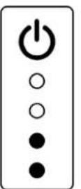 |  |  |  |  |

Tip
- After the aircraft is connected to the remote controller, you can check the current smart battery level of the aircraft in the top status notification bar or on the "Battery Information" page of the Autel Enterprise App. For more information, see "6.3 Status Notification Bar" and "6.5.5 Aircraft Battery" in Chapter 6.
5.3.3 Smart Battery Self-heating
The smart battery has a self-heating function, which can increase the battery temperature in low-temperature environments, helping maintain good output performance.
- When the smart battery is installed in the aircraft and the battery power is turned on, if the battery temperature is lower than 15°C, the battery self-heating function will be activated. After the aircraft takes off, the battery self-heating function will be automatically turned off.
- If the smart battery is not installed in the aircraft, short press the power button for 1 second and then long press the power button for 2 seconds to activate the battery self-heating function to keep the battery temperature between 15^ and 20^ for 10 minutes. At this point, if you want to exit the battery self-heating function, short press the power button for 1 second, and then long press the power button for 2 seconds.
- When the smart battery is connected to the battery charger and the battery power is turned on, if the battery temperature is lower than 10^(50^) , the charger will supply power to the smart battery for self-heating. Once the battery temperature reaches 15^ , the self-heating function will be turned off.

Important
- When the self-heating function of the smart battery is manually activated, the battery should have at least around 10% of remaining power for self-heating.
When the smart battery is in the states of self-heating and heat preservation, the statuses of the battery level indicators are shown in the following table.

flowchart
graph TD
    A["LED1"] --> B["LED3"]
    C["LED2"] --> D["LED4"]
    style A fill:#f9f,stroke:#333
    style C fill:#f9f,stroke:#333
    style B fill:#ccf,stroke:#333
    style D fill:#ccf,stroke:#333
Fig 5-5 Self-heating State

Fig 5-6 Heat Preservation State
Table 5-3 Battery Level Indicator Status
| No. | Description |
| 1 | LED1, LED3 and LED2, LED4 blink alternately in groups, indicating that it is heating. |
| 2 | The 4 LEDs blink at the same time, indicating that it has entered the heat preservation state. |
| : Green light blinking Off | |

Warning
- When the temperature of the smart battery is lower than -10^ or higher than 75^ , the aircraft will not be allowed to take off. It is recommended to wait until the self-heating is over or the battery naturally cools down to an appropriate temperature before operating.
- When the temperature of the smart battery is lower than 10°C, the internal resistance of the battery will increase and the voltage will drop suddenly due to the low temperature, which will reduce the usable capacity of the battery and reduce the operating time of the aircraft. In low-temperature environments, make sure that the battery is fully charged before taking off.
- If the battery level of the smart battery is lower than 50%, it is not recommended to take off. When the battery level is low, it is difficult to activate the battery, which will reduce flight safety.
- During the flight, when the Autel Enterprise App prompts a low battery alarm, it is recommended to immediately return to the home point or land.
-
In some low-temperature environments, even if the self-heating function is activated, the battery temperature may still not reach the usable temperature. In such cases, please add insulation measures during the heating process.
-
In order to get the best performance from the smart battery, it is recommended to keep the battery temperature between 15^ to 35^ before flying.
- In a low-temperature environment, the self-heating time of the battery may be longer. It is recommended that you keep the battery warm in advance to shorten the self-heating time.
5.3.4 Charging the Smart Battery
Connect the charging interface of the official battery charger to the notch of the metal electrode of the smart battery, and connect the plug to the AC power supply (100-240 V\~ 50/60 Hz).

Fig 5-7 Use the Battery Charger to Charge the Smart Battery
Table 5-4 Battery Level Indicator Status (While Charging)
| 0~25% | 26~50% | 51~75% | 76~100% | |
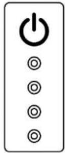 |  | 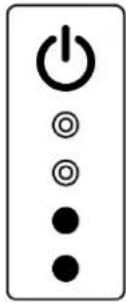 |  | |
| : Green light is always on Green light blinking | ||||

Warning
- Do not charge a battery that emits smoke, is bulged, leaks liquids, or has a damaged appearance.
-
Do not use damaged charging devices to charge the smart battery.
-
Modifying the official smart battery or charging device provided by Autel Robotics is prohibited.
- Only use the battery and charging device provided by Autel Robotics. Autel Robotics is not responsible for any consequences, such as battery accidents and flight failure, caused by the use of third-party batteries or charging devices.
- Keep the smart battery away from flammable and explosive items during charging.
- After the smart battery is fully charged, disconnect the connection between the charger and the smart battery and power supply promptly.
- After flight, it is recommended to wait until the smart battery naturally cools down to an appropriate temperature before charging the battery. If the temperature of the smart battery is higher than 40°C, when the battery is connected to the charging device, the battery temperature protection function will be activated, and the battery cannot be charged until its temperature drops below 40°C.

Note
- It is recommended to fully charge the smart battery of the aircraft before the aircraft takes off.
- Generally, it takes about 90 minutes to fully charge the smart battery of the aircraft, but the charging time is related to the remaining battery level.
Table 5-5 Other Battery Indicator Warning Instructions
| LED1 | LED2 | LED3 | LED4 | Warning Description |
| 0 | 0 | 0 | 0 | The temperature is too high for charging. |
| 0 | 0 | 0 | 0 | The charging current is too high, which causes a short circuit. |
| 0 | 0 | 0 | 0 | A circuit overcurrent, a circuit overload, or a short circuit occurs during battery discharge. |
⑩: Indicator light blinking :Off
5.4 Storing and Transporting the Smart Battery
When storing the smart battery, keep the battery away from water or heat sources and store it in a dry, well-ventilated environment at room temperature.
Ideal storage conditions: The battery level is at around 60%, the ambient temperature is between 22°C to 28°C, and the ambient humidity is 65%±20% RH.
The energy of the MDH_10000_23700 smart battery is 237 Wh (capacity is 10000 mAh). Please refer to local lithium battery transportation policies for battery shipping or carrying.

Tip
- Please be noted that according to airline requirements, lithium batteries over 160Wh cannot be carried on board.

Warning
- Before storing or transporting the smart battery, please turn off the battery.
- Store the smart battery out of the reach of children and pets.
- Store the smart battery away from direct sunlight, water, or reactive chemicals.
- Do not expose the smart battery to open flame, explosives, or other hazards.
- Do not store the smart battery in extreme temperatures. Otherwise, the lifespan of the battery may be shortened and the battery may even become damaged or ineffective. If the battery is not used for more than 1 day, it should be stored below 30^ (at room temperature).
- Do not place the smart battery in a microwave or pressure cooker.
- Do not place the smart battery directly on conductive surfaces (such as metal shells or panels).
- Do not place heavy objects on the smart battery. When subject to an external force, the battery may be damaged or even catch fire or explode.
- Do not store or transport the smart battery with sharp objects, watches, metal necklaces, earrings, or other metal items.
- Do not transport batteries that have a damaged appearance or a battery level of more than 30%.
- If the smart battery is left idle for a long time, please charge it every three months to avoid a shortened battery lifespan resulting from long-term low battery levels.
5.5 Maintaining and Handling the Smart Battery
5.5.1 Maintaining the Smart Battery
In order to maintain the activity of the smart battery of the aircraft, it is recommended to perform battery maintenance if any of the following conditions are met:
- It is recommended to perform battery maintenance for the smart battery every 50 times of battery cycle.
● The idle time of the smart battery reaches 3 months. - Occasionally, there are situations that affect the lifespan of the smart battery. In this case, you can try maintenance and repair.
● The Autel Enterprise App reminds you when the smart battery needs maintenance.
The following battery maintenance check items are available for the smart battery:
- Perform a standard charge and discharge operation on the smart battery.
- Insert the smart battery into the aircraft and turn on the power. Check the battery information through the Autel Enterprise App, whether the voltage difference between the battery cells is less than 0.1 V, and whether the battery firmware is up to date.
-
Check whether the smart battery is bulged, leaked, or damaged.
-
Check the battery connector for dirt, damage, or rust.
5.5.2 Standard Charging and Discharging Process
Use the maintenance charging mode of the original charger, and proceed as follows:
- Use the battery charger included in the standard aircraft kit to charge the smart battery to 100% and let the battery sit for 1 hour.
- Insert the smart battery into the aircraft to fly, control the aircraft to land when the remaining battery level is less than 20%, and then take out the battery.
- Let the smart battery sit for 8 hours.
- After the above operations are completed, a standard battery charging and discharging operation is completed.
5.5.3 Smart Battery Replacement Standards
● There are obvious bulges, leakage, and damage on the smart battery surface.
- Damage to or irreparable rust on the metal contacts at the power supply interface of the smart battery.
- After the number of cycles of the smart battery reaches 200, it is recommended to replace the battery with a new one.
- After 2 consecutive standard charge and discharge operations, if the abnormal battery still cannot be repaired, it is recommended to replace it with a new one.
5.5.4 Recycling the Smart Battery
- If the smart battery is discarded due to damage, leakage, or other issues that compromise the integrity of the battery shell, it is recommended to completely immerse the battery in an insulated bucket filled with 5% salt water for more than 48 hours until the battery is completely discharged.
- If the smart battery is normally retired, confirm that it is completely discharged, and then properly recycle it according to local lithium battery waste disposal policies to avoid environmental pollution.
Important
- When the smart battery catches fire, please use solid fire extinguishers such as sand or dry powder extinguishers.
Chapter 6 Autel Enterprise App
6.1 Software Introduction
The Autel Enterprise App is a flight control software developed by Autel Robotics for enterprise applications. The software integrates a variety of professional functions to quickly get started and improve efficiency; through a variety of built-in intelligent flight functions, it can realize highly intelligent aircraft operations and empower industry applications. Cooperating with the Autel Enterprise App, the aircraft can be widely used in public safety, inspection, and other industries. Also, it supports multiple mission modes such as waypoint missions, rectangular missions, and polygonal missions.

Note
- More mission modes will be available after subsequent app and firmware updates, and some UI interfaces may differ due to version updates.
6.2 Main Interface
After pairing the remote controller with the aircraft, open the Autel Enterprise App, and you will automatically enter the main interface.

Fig 6-1 Main Interface of the Autel Enterprise App
Table 6-1 Details of the Main Interface of the Autel Enterprise App
| No. | name | Description |
| 1 | Status Notification Bar | Displays the flight mode, warning information, flight status, battery level of the remote controller and aircraft, remote controller signal, operating status of the obstacle avoidance system, and other information. |
| 2 | Shortcut Toolbar | Offers quick access to certain frequently used functions. |
| 3 | "Map" Preview Interface | Offers access to a full-screen map interface. You can freely scroll on the interface to view the map. |
| 4 | "Zoom" Preview Interface | Provides access to the full-screen interface of the zoom camera. |
| 5 | "Infrared" Preview Interface | Offers access to the full-screen interface of the thermal camera. |
| 6 | Camera Function Area | Offers access to the functions related to camera control, settings viewing, and gimbal camera switching. |
| 7 | Attitude Ball | Displays real-time flight-related data of the aircraft to assist in flight. |

Tip
- The Autel Enterprise App can automatically identify the gimbal camera model mounted on the aircraft and adjust the display content of the main interface accordingly. When an aircraft with a different gimbal camera model is connected to the remote controller, the display content on the main interface of the Autel Enterprise App may vary.
Table 6-2 Multi-Screen Switching Operations on the Main Interface
| No. | Icon | Meaning | Description |
| 1 |  | Dual-Screen Mode | Tap this icon to enter the dual-screen mode.The left and right sides of the remote controller screen can display any two of the four preview interfaces, which are "Map", "Wide" "Zoom", and "Infrared". |
| 2 |  | Three-Screen Mode | Tap this icon to enter the three-screen mode. The Autel Enterprise App defaults to the three-screen mode.The left side of the remote controller screen displays the "Map" preview interface, the upper-right side displays the "Zoom" preview interface, and thelower-right side displays the "Infrared" preview interface. |
| 3 |  | Maximize Window | Tap this icon to adjust a preview interface to the corresponding full-screen interface. |

Tip
- In any camera interface or camera preview interface, you can swipe up anywhere to hide all function icons and swipe down to restore the display of function icons.
6.3 Status Notification Bar

Fig 6-2 Status Notification Bar of the Autel Enterprise App
Table 6-3 Details of the Status Notification Bar of the Autel Enterprise App
| No. | Icon Meaning | Description | |
| 1 |  | Status and Fault Warning | Displays the current warning information of the aircraft:➢ Gray indicates that the remote controller is not connected to the aircraft.➢ Orange indicates a medium-level warning. In this case, the aircraft will not be prohibited from taking off but should pay attention to flight safety.➢ Red indicates a high-level warning. In this case, the aircraft will be prohibited from taking off and can take off only after you solve the fault. |
| 2 |  | Flight Status | Displays the current flight status.There are 3 modes: GNSS mode, visual positioning mode, and ATTI mode. For more information, see "3.8.1 Flight Status" in Chapter 3. |
| 3 |  | Mission Status | Displays the current mission type and mission status of the aircraft. |
| 4 | [wwkz] | No SD Card | Indicates that there is no microSD card installed in the gimbal currently. |
| 5 | [w8cz] | Remote Controller Battery | Displays the current battery level of the remote controller. |
| 6 |  | Remote Controller Signal Status | 1. Displays the current communication signal status between the remote controller and the aircraft. |
| 2. Tap this icon to display the specific signal status:When the signal is 3-5 grids, the remote controller signal is displayed as strong.When the signal is 1-2 grids, the remote controller signal is displayed as weak.3. When the remote controller is not connected to the aircraft, the remote controller signal is displayed in gray color. | |||
| 7 |  | RTK Signal Status | Displays the current RTK signal strength and positioning accuracy level. |
| 8 |  | GNSS Signal Status | 1. Displays the current GNSS positioning signal status of the aircraft.2. Tap this icon to display the specific signal status and satellite connection status.3. If the aircraft receives no GNSS signal, the GNSS signal is displayed in gray color. |
| 9 |  | Aircraft Battery | 1. Displays the current battery information of the aircraft.2. Tap this icon to display the battery level, voltage, and temperature of the aircraft battery. |
| 10 |  | Obstacle Avoidance System | Displays the current activation status of the aircraft obstacle avoidance system.➢ Green indicates that the obstacle avoidance system is activated.➢ Red indicates that the obstacle avoidance system is deactivated. |
| 11 |  | Speed Mode Display | Displays the current speed mode of the aircraft. Four modes are available, that is, Slow mode, Smooth mode, Standard mode, and Ludicrous mode. For more information about the speed modes, see “3.8.2 Flight Modes” in Chapter 3. |
6.4 Shortcut Toolbar
The shortcut toolbar is displayed at the bottom of the system status notification bar of the Autel Enterprise App, which allows you to quickly activate certain functions.
In the shortcut toolbar, you can long press and drag the function icons to customize the sorting. At the same time, you can also tap on the "☐" icon to enter "Shortcuts" and then tap on the "☐" icon on the right side of "Shortcuts" to add a function icon into or delete a function icon from the shortcut toolbar.
| Tip |
| ● You can add a maximum of 12 function icons to the shortcut toolbar. |

Fig 6-3 Shortcut Toolbar
Table 6-4 Shortcut Toolbar Details
| No. | Icon | Name | Description |
| 1 |  | Stitch | Tap this icon to configure the remote controller to connect to a server with 2D and 3D mapping software installed, which allows for fast mapping. |
| 2 |  | Laser | Tap this icon to automatically measure the distance from the target point at the center of the lens to the aircraft, as well as the target point's altitude and coordinates (longitude and latitude). |
| 3 |  | RECOG | Tap this icon to intelligently identify the target object type. |
| 4 |  | Waypoint | Tap this icon to enter the "Waypoint" mission editing interface. |
| 5 |  | Missions | Tap this icon to enter the "Missions" interface, where you can query, edit, favorite, and delete previously saved historical flight missions. |
| 6 |  | Aux Light | Tap this icon to turn on the bottom LED auxiliary light, which can assist in landing and enhance the aircraft's visual sensing capabilities in weak-light environments. |
| 7 |  | Screenshot | Tap this icon to capture the current screen in a screenshot. |
| 8 |  | Recording | Tap this icon to start recording the current screen. |
| 9 |  | Brightness | Tap this icon to move the slider left and right to adjust the brightness of the camera. |
| 10 |  | Defog | Tap this icon to make the shooting or recording scene more transparent and enhance color contrast, which is used to eliminate the "fogging phenomenon" in the picture or the lack of picture clarity caused by smog. |
| 11 |  | Night Mode | Tap this icon to enter night shooting mode. Even when shooting in a low-light environment, the picture will remain clear. |
| 12 |  | PinPoint | Tap this icon to display information such as the latitude, longitude, and altitude of the target point selected on the image transmission interface. |
| 13 |  | Tripod | Tap this icon, and the aircraft will automatically lock onto the selected target. |
| 14 |  | More | Tap this icon to enter the "Shortcuts", where you can view all shortcut function icons. |
| 15 |  | Edit Shortcuts | Tap this icon to add function icons from "Shortcuts" to the "Shortcut Toolbar" or move the function icons in the "Shortcut Toolbar" to "Shortcuts". |
| 16 |  | Strobe | Tap this icon to turn on the strobe on the top of the aircraft fuselage. |
| 17 |  | Bypass | Tap this icon to quickly set the OA mode of the aircraft to "Bypass". |
| 18 |  | Rectangle | Tap this icon to enter the "Rectangle" mission editing interface. |
| 19 |  | Polygon | Tap this icon to enter the "Polygon" mission editing interface. |
| 20 |  | Record | Tap this icon to record real-time attitude, motion, and other parameters of the aircraft and gimbal camera during a flight mission, which allows for repeating the operation process for the next mission. |
| 21 |  | Album | Tap this icon to view materials from the aircraft's album and the local album and download or delete them. |
| 22 |  | Professional Imagery | Tap this icon to make professional settings for the gimbal camera parameters. |
| 23 |  | Live-RC | Tap this icon to set live streaming of real-time aerial videos from the aircraft. Two streaming methods, that is, RTMP and GB28181, are supported. |
| 24 |  | Support | Tap this icon to enter the "Personal Center" interface. |
| 25 |  | Settings | Tap this icon to enter the "Settings" interface. |
| 26 |  | Flight Log | Tap this icon to view the flight logs of the aircraft or synchronize them to a third-party platform. To use this function, you need to log in to your Autel account. |
| 27 |  | Encrypt | Tap this icon to set a security password for encrypting captured media materials. |
| 28 |  | Rectangle | Tap this icon to enter the "Rectangle" mission editing interface. |
6.5 "Settings" Interface
On the main interface of the Autel Enterprise App, tap the "💡" icon on the right side of the shortcut toolbar, and then tap the "💡" icon to enter the "Settings" interface.
In the "Settings" interface, you can set parameters such as flight control, obstacle avoidance, remote controller, image transmission, battery, and gimbal.
6.5.1 Flight Control Parameter Setting
In the sidebar of the "Settings" interface, tap the "1" icon to enter the "Flight Control Parameter Setting" interface, where you can set the relevant flight control parameters for the aircraft, as shown below.

Fig 6-4 "Flight Control Parameter Setting" interface
■ Set RTH Altitude
Tap the "RTH Altitude" edit box and enter the value. When executing an auto-return, the aircraft will rise to the RTH altitude before starting the return process.

Warning
- Although the Autel Enterprise App allows you to set a flight altitude within the range of 20-800 meters, this does not mean that the set altitude complies with local laws and regulations.
- The RTH altitude should be set higher than the altitude of obstacles within the flight operation area.
- The RTH altitude setting should comply with local (within the flight operation area) laws and regulations.
- For information about adjusting the RTH altitude of the aircraft, see "2.7.4 Auto-return Mechanism" in Chapter 2.
■ Turn On/Off Altitude Limit
Tap the button on the right side of "Altitude Limit" to turn on or off the altitude limit function.
If this function is turned on, enter the altitude limit value in the edit box of "Altitude Limit (20-800m)" that pops up below, and the aircraft can rise up to the maximum altitude specified.
If this function is turned off, the aircraft can keep ascending according to your operation until the battery is exhausted.
| Tip |
| ● The altitude limit should not be set lower than the RTH altitude value.● The altitude limit setting should comply with local (within the flight operation area) laws and regulations. Flying the aircraft in an unsuitable flight altitude may have legal risks. Please comply with the fight safety requirements of relevant areas during flight operations. |
■ Turn On/Off Distance Limit
Tap the button on the right side of "Distance Limit" to turn on or off the distance limit function.
If this function is turned on, enter the distance limit value in the edit box of "Distance Limit (20-5000m)" that pops up below, and the aircraft will fly within a circle with the take-off point as the center and the distance limit value as the radius.
If this function is turned off, the aircraft can keep moving according to your operation until the battery is exhausted.
| Tip |
| ● Appropriate altitude limit and distance limit settings can improve flight safety. |
■ Set Flight Mode
Tap the "Flight Mode" drop-down list, and then select the appropriate mode from Slow, Smooth, Standard, and Ludicrous, that is, set the default speed mode every time you open the Autel Enterprise App. For the meaning of each mode, see "3.8.2 Flight Modes" in Chapter 3.
■ Set Home Point
Tap "Aircraft" or "RC" to set the home point.
If "Aircraft" is selected, the home point is the position where the aircraft took off this time.
If "RC" is selected, the home point is the current position of the remote controller.
| Note |
| ● If the home point is not set, the aircraft will record the take-off point as the default home point. |
■ Calibrate Compass/ IMU
Perform the calibration operation as instructed in the Autel Enterprise App. For more information, see "2.11 Aircraft Calibration" in Chapter 2.
■ Set Lost Action
Tap the drop-down list of "Lost Action" to set the aircraft actions when disconnected.
Lost action refers to the action that the aircraft will perform when the aircraft is disconnected from the remote controller during flight. By default, the lost action is set to "Return to Home".
If "Return to Home" is selected, when the aircraft disconnects, the aircraft will automatically return to the home point.
If "Hovering" is selected, when the aircraft disconnects, the aircraft will hover at the current position.
If "Land" is selected, when the aircraft disconnects, the aircraft will land at the current position.

Tip
- When the aircraft is disconnected from the remote controller, the aircraft will decelerate. If the connection is not restored after 4 seconds, the aircraft will execute the "Lost Action".
- When the aircraft initiates a return to home due to a disconnection, even if the aircraft reconnects to the remote controller, it will continue the return process. In this case, you can short press the "Pause" button on the remote controller to pause the return process or long press the "Pause" button for 2 seconds to exit the return process to regain control of the aircraft.
6.5.2 OA Settings
In the sidebar of the "Settings" interface, tap the "icon to enter the "OA Settings" interface, where you can set the OA system, brake distance, warning distance, radar display, obstacle detection notification sound, landing protection, and OA mode of the aircraft, as shown below.
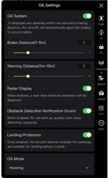
Fig 6-5 "OA Settings" Interface
■ Turn On/Off OA System
Tap the button to the right of "OA system" to turn on/off the OA system function.
If this function is turned on, you can set the brake distance. Enter a value in the edit box to the right of "Brake Distance (1-5m)" that pops up below, or adjust the value by moving the slider below left and right. When the aircraft detects an obstacle, it will stop at the brake distance as set.
If this function is turned off, when the aircraft detects an obstacle, it will not stop.

Warning
● To ensure flight safety, it is recommended to always turn the OA system on.
- When the flight mode of the aircraft is set to "Ludicrous", the OA system function is unavailable.
■ Set Warning Distance
Enter a value in the edit box to the right of "Warning Distance (1m-10m)", or adjust the value by moving the slider below left and right. If the aircraft detects an obstacle, it will send a warning at the warning distance as set.
■ Turn On/Off Radar Display
Tap the button to the right of "Radar Display" to turn on or off the radar display function.
If this function is turned on, when the aircraft detects an obstacle, it will provide risk warnings on the camera interface based on the set brake/warning distance.
If this function is turned off, when the aircraft detects an obstacle, it will not provide risk warnings on the camera interface.
■ Turn On/Off Obstacle Detection Notification Sound
Tap the button to the right of "Obstacle Detection Notification Sound" to turn on or off the obstacle detection notification sound function.
If this function is turned on, when the aircraft detects an obstacle, it will emit an audible alert.
■ Turn On/Off Landing Protection
Tap the button to the right of "Landing Protection" to turn on or off the landing protection function.
If this function is turned on, the aircraft will detect whether the ground surfaces are suitable for landing before it lands.

Tip
- After the landing protection function is turned on, if the aircraft detects that the ground surface is not suitable for landing, it will keep hovering over the landing point. In this case, you need to use the command sticks to manually control the aircraft to land at an appropriate location.
OA Mode
Select the desired OA mode from the drop-down list of "OA Mode".
After the OA mode is set, the aircraft will perform the corresponding action when detecting obstacles. The default OA mode is "Hovering".
If "Hovering" is selected, when the aircraft detects an obstacle during flight, it will hover at the current position.
If "Bypass" is selected, when the aircraft detects an obstacle during flight, it will select an optimal path to bypass the obstacle.

Note
- In the current version, when the OA mode is set to "Bypass", the aircraft will ascend to an altitude that allows it to bypass obstacles. In future versions, the aircraft will have the capability to prioritize bypassing obstacles from the left or right side of the obstacles.
6.5.3 RC Settings
In the sidebar of the "Settings" interface, tap the "☐" icon to enter the "RC Settings" interface, where you can set the stick mode, RC custom buttons, and EXP, and calibrate the remote controller, as shown below.

Fig 6-6 "RC Settings" Interface
■ Set Stick Mode
Tap "Stick Mode" and select one of the three stick modes, that is, Mode 1, Mode 2, and Mode 3, according to your preferences. For the differences between the three stick modes, see "4.10.1 Stick Modes" in Chapter 4. The default stick mode is Mode 2.
■ Calibrate the Remote Controller
Perform the calibration operation as instructed in the Autel Enterprise App. For more information, see "4.13 Calibrating the Remote Controller" in Chapter 4.
■ Set RC Custom Button C1/C2
Tap "RC Custom Button", and then tap the drop-down list of C1 or C2, and select the customized function according to your needs. For more information, see "4.11.1 Custom Keys C1 and C2" in Chapter 4.
■ Set EXP
After tapping "EXP", drag the coordinate system curves of "Ascend - Descend", "Turn Right - Turn Left", and "Forward/Move Right - Backward/Move Left" according to your needs, or input coefficients (in the range of 0.2-0.7) in each edit box.
The X-axis is the physical output of the command stick, and the Y-axis is the logical output of the command stick. That is, the X-axis represents the movement generated by the current command stick move, and the Y-axis represents the actual response strength of the current aircraft.
When the coefficient is 0.2, the slope of the curve increases gradually, which is convenient for fine-tuning; when the coefficient is 0.7, the slope of the curve gradually decreases, and the aircraft responds strongly when the command stick is slightly moved. Tap "Reset EXP Parameters" to reset the EXP parameters.
■ Connect to Aircraft
Connect to aircraft: If the remote controller is currently not connected to the aircraft, tap "Connect to aircraft", and then double-click the power button of the aircraft according to the pop-up notification to complete the frequency pairing between the remote controller and the aircraft. For more information, see "4.9 Frequency Pairing With the Remote Controller" in Chapter 4.
➢ Cancel: If the remote controller is currently connected to the aircraft, tap "Connect to aircraft", and then tap "Cancel" in the pop-up window to disconnect the remote controller from the aircraft.
6.5.4 Image Transmission Settings
In the sidebar of the "Settings" interface, tap the " (p) " icon to enter the "Image Transmission Settings" interface, where you can set the image transmission mode, transmission frequency band, and split screen effect, as shown below.

Fig 6-7 "Image Transmission Settings" Interface
■ Set Image Transmission Mode
Tap the drop-down list of "Image Transmission Mode" and select "Smooth" or "HD" according to your needs. Once selected, the remote controller will receive and display the image transmission screen at the selected resolution.

Tip
● "Smooth" means 720P and "HD" means 1080P.
■ Set Transmission Frequency Band
Tap the drop-down list of "Transmission Frequency Band" and select a transmission frequency band according to your needs.
➢ Auto: The optimal transmission frequency band is automatically selected for image transmission between the aircraft and the remote controller.
➢ 2.4G: The 2.4 GHz frequency band is used for image transmission between the aircraft and the remote controller.
➢ 5.8G: The 5.8 GHz frequency band is used for image transmission between the aircraft and the remote controller.
■ Set Split Screen Effect
Tap the drop-down list of "Split Screen Effect", and select "Uniform Scale" or "Fit the Screen" according to your needs.
Uniform Scale: In dual-screen mode, the image transmission screen is proportionally reduced.
➢ Fit the screen: In dual-screen mode, the image transmission screen is stretched to cover the screen.

Tip
- The split screen effect settings are only effective when the remote controller is in dual-screen mode.
6.5.5 Aircraft Battery
In the sidebar of the "Settings" interface, tap the "图标" icon to enter the "Battery Information" interface, where you can view the basic information of the current aircraft battery (that is, smart battery), set the battery warning threshold, and enable the hot swap battery function, as shown below.

Fig 6-8 "Battery Information" Interface
■ View Basic Information of the Smart Battery
Here, you can view the real-time status of the battery and the estimated flight time of the aircraft with the current battery level. Please refer to the parameters in the following table to view the basic information of the battery, so as to deal with it in time when the battery condition is not good.
Table 6-5 Power Parameter Details
| Parameter | Description |
| Battery Level | If the battery level is higher than or equal to the critically low battery warning threshold and lower than or equal to the low battery warning threshold. In this case, there will be an orange warning.If the battery level is lower than or equal to the critically low battery warning threshold, there will be a red warning. |
| Temperature | The temperature range is -10°C-75°C. 6°C ≤ battery temperature ≤ 74°C, the temperature is normal.-10°C ≤ battery temperature ≤ 5°C, the temperature is low, and there will be an orange warning.If the battery temperature is lower than or equal to -10°C, the temperature is too low and there will be a red warning.If the battery temperature is ≥75°C, the temperature is high and there will be a red warning.If the battery temperature is ≥95°C, the temperature is too high and there will be a red warning. |
| Voltage | Normal voltage range: 18.5-26.7V. When it exceeds the normal range, there will be a red warning. |
| Discharge Times | The normal range of the number of discharges is 0-200 times. When it exceeds the normal range, there will be a red warning. |
■ Set Battery Warning Threshold
Move the slider left or right to set warning thresholds for low battery and critically low battery.
➢ Critically Low Battery Warning: Red status. The adjustable range is from 8% to 25%.
Low Battery Warning: Orange status. The adjustable range is from 15% to 50%. The low battery warning threshold should be at least 5% higher than the critically low battery warning threshold.
6.5.6 Gimbal Settings
In the sidebar of the "Settings" interface, tap the " 🔍" icon to enter the "Gimbal Settings" interface, where you can set the gimbal pitch sensitivity and extended pitch angle, or calibrate and adjust the gimbal, as shown below.

Fig 6-9 "Gimbal Settings" Interface
■ Set Gimbal Pitch Sensitivity
Enter a value in the edit box to the right of "Gimbal Pitch Sensitivity", or move the slider left or right to adjust the value, so as to set the number of degrees the gimbal rotates on the pitch axis per second (unit: °/second).
■ Turn On/Off Extended Pitch Angle
Tap the button to the right of "Extended Pitch Angle" to turn on the upward gimbal rotation function.
If this function is turned on, the gimbal can rotate up to 30 degrees above the level baseline.
If this function is turned off, the gimbal can only maintain a level or downward rotation and cannot rotate upwards to switch to a pitch view.
■ Gimbal Calibration
When there is an abnormality in the gimbal, tap "Gimbal Calibration", and then tap the "Start calibration" button, and the gimbal will automatically start calibrating. For more information, see "2.11.3 Gimbal Calibration" in Chapter 2.
■ Gimbal Adjustment
When the position of the gimbal tilts, tap "Gimbal Adjustment" and tap the buttons under the functions of "Roll", "Yaw", and "Pitch" to adjust the gimbal, so that the horizontal and vertical axes
on the screen remain aligned to the reference objects on the three-screen image transmission screen.
■ Gimbal Parameters Reset
Tap the "Gimbal Parameters Reset" button, and then tap the "Confirm" button to reset the gimbal parameters.
6.5.7 RTK Settings
In the sidebar of the "Settings" interface, tap the "RTK" icon to enter the "RTK Settings" interface, Users can enable the RTK positioning function, check the RTK connection status, and configure the reception mode for RTK signals.
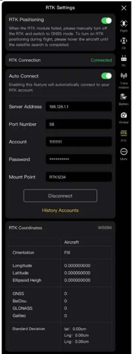
Fig 6-10 "RTK Settings" Interface
■ Enable/Disable RTK Positioning
To enable or disable RTK positioning, tap the button on the right side of "RTK Positioning".

Warning
- In case of RTK module issues, please manually disable RTK positioning and switch back to GNSS mode.
- When activating RTK positioning during flight, please hover the aircraft and wait for satellite searching.
■ Check RTK Connection
To check the RTK network status, enable RTK positioning, enter the RTK account, and tap "Log In Account" to establish the RTK network connection.
If the connection is successful, it will display "Connection Successful."
If there is an issue, it will display "Connection Failed" along with a reason for the failure.
■ RTK Receive Signal Setting
For setting the RTK signal reception, enter the network RTK server address, port number, account, password, and mount point in the RTK service configuration section.
Tap "Log In Account" to log in to the network RTK service. If there's an issue with the configuration, it will provide relevant prompts.
➢ Tap "History Accounts" to view previously configured RTK accounts. The aircraft supports saving multiple network RTK accounts.
Tap the button on the right side of "Auto Connect" to enable or disable automatic login RTK accounts.
■ Check RTK Coordinates
To view the RTK coordinate system, after establishing the RTK network connection, check the coordinate system type, RTK orientation mode, latitude, longitude, altitude, satellite quantity, and standard deviation.
6.5.8 More
In the sidebar of the "Settings" interface, tap the "☐" icon to enter the "More" interface, where you can configure unit settings, light settings, safety, target recognition settings, and the language settings of the Autel Enterprise App for the aircraft and manually check for updates to the App or firmware.

Fig 6-11 "More" interface
■ Unit Settings
Tap "Units Settings", and then set "Speed/Distance Units", "Area Units", "Temperature Units", and "Coordinate Format" according to your needs. After the setting, the Autel Enterprise App will display relevant parameters in the specified units.
■ Light Settings
Tap "Light Settings", and then set "Strobe", and "Aux Light" according to your needs.
S
- Turn On/Off Strobe
Tap the button to the right of "Strobe" to turn on or off the strobe on the top of the fuselage.

Warning
- When flying at night, please turn on the strobe to ensure flight safety.
- Do not look directly at the strobe while they are on to avoid vision damage caused by strong light.
- Set Aux Light
Tap the drop-down list of "Aux Light" and then select "Auto", "On", or "Off" according to your needs.
If "Auto" is selected, the auxiliary bottom light is automatically turned on or off according to ambient brightness.
If "On" is selected, the auxiliary bottom light is always on by default.
If "Off" is selected, the auxiliary bottom light is off by default.

Tip
- The auxiliary bottom light is mainly used to enhance the ambient brightness of the landing point during the landing of the aircraft, improve the sensing performance of the downward visual sensing system, and ensure landing safety.
■ Turn On/Off Visual Positioning
Tap "Safety", and then tap the button to the right of "Visual Positioning" to turn on or off the visual positioning function.
If the visual positioning function is turned on, the aircraft will hover in a place with a poor GNSS signal.
| Tip |
| ● Turning on visual positioning is a must to enter visual positioning mode. For more information, see “3.8.1 Flight Status” in Chapter 3. |
■ Turn On/Off Submit Flight Data to CAAC
Tap "Safety", and then tap the button to the right of "Submit Flight Data to CAAC" to turn on or off the function of submitting flight data to CAAC.
| Important |
| It is recommended to turn on the function of submitting flight data to CAAC. According to Chinese laws and regulations, flight data must be submitted in real time to the official system of the Civil Aviation Administration of China (CAAC) via the internet.When the network is poor, the relevant flight data will be cached on your local device, and the Autel Enterprise App will not store or forward the data to other services. |
■ Enter Registration No.
Tap "Safety" and then tap "Registration No." to enter the real-name registration number of the aircraft.
| Important |
| ● According to Chinese laws and regulations, real-name registration is required for aircraft. For more information, see “2.1 Legal Use Notice” in Chapter 2. |
■ Remote ID
Tap "Safety" and then tap "Remote ID". After entering the Remote ID, you can broadcast relevant information about the aircraft for identification by nearby devices.
| Important |
| ● According to local laws and regulations, perform real-name registration for aircraft. For more information, see “2.1 Legal Use Notice” in Chapter 2. |
■ Emergency Stop Propellers During Flight
Tap "Safety" and then tap the drop-down list of "Emergency Stop Propellers During Flight" to make relevant settings according to your needs.
If "Off" is selected, the "Emergency Stop Propellers During Flight" function will be disabled.
If "On" is selected, you can stop the propellers of the aircraft from spinning at any time during flight by simultaneously pushing the two command sticks inward or outward.
If "Only in case of failure" is selected, you can stop the propellers of the aircraft from spinning by simultaneously pushing the two command sticks inward or outward only in the case of aircraft malfunctions.
Important
- Please use the "Emergency Stop Propellers During Flight" function with caution. Once the propellers stop, the aircraft will fall freely without control.
- This function is only used to reduce additional harm or damage caused by aircraft malfunctions. Please stay away from crowds or buildings when using this function.
● After the "Emergency Stop Propellers During Flight" function is enabled, please stop using the aircraft and contact Autel Robotics to inspect the power system of the aircraft.
■ View Version Information
Tap "About", and you can view the firmware version and the serial number of the aircraft, remote controller, gimbal, and battery, as well as the version of the Autel Enterprise App, and check for versions and perform updates for the App and firmware.
■ Language Settings
Tap the drop-down list of "Language Settings" and choose one from Simplified Chinese, English, Traditional Chinese, Japanese, and Spanish. After you confirm the selection, the Autel Enterprise App will automatically restart and display in the chosen language.
6.6 Attitude Ball
The attitude ball is mainly used to dynamically display the relative positions of the aircraft, remote controller, and home point, and display the relevant attitude, flight speed, battery level, operating time, and other flight safety data of the aircraft. Any changes in the aircraft's status will be reflected in the attitude ball.

Fig 6-12 Attitude Ball
Table 6-6 Attitude Ball Details
| No. | Description | Description |
| 1 | Estimated Remaining Flight Time of the Aircraft | Displays the current remaining battery level and estimated remaining flight time of the aircraft. |
| 2 MSL Altitude | Refers to the current altitude of the aircraft relative to the mean sea level (MSL). | |
| 3 Aircraft Position | Displays the current position of the aircraft, which can help you observe the approximate position between the aircraft and the remote controller. | |
| 4 Aircraft Heading | Displays the current nose orientation of the aircraft. If the aircraft is no longer visible in the line of sight, the aircraft can be controlled to return to the home point based on the position and heading of the aircraft. | |
| 5 | Gimbal Direction | Displays the current gimbal orientation of the aircraft. |
| 6 Vertical Altitude | Refers to the current vertical altitude of the aircraft relative to the take-off point. | |
| 7 | Vertical Speed | Refers to the current vertical flight speed of the aircraft. |
| 8 | Remote Controller Location | Displays the current position of the remote controller, which can help you observe the approximate position between the aircraft and the remote controller. |
| 9 | Home Point | Refers to the set home point of the aircraft. |
| 10 | Horizontal Distance | Refers to the current horizontal distance from the aircraft to the take-off point. |
| 11 | Horizontal Speed | Refers to the current horizontal flight speed of the aircraft. |
| 12 Aircraft Battery | Displays the real-time remaining battery level of the aircraft in the dynamic circular battery bar. | |
6.7 "Map" Interface
On the main interface of the Autel Enterprise App, tap the "4" icon in the corner of the "Map" preview interface, or tap the "Map" mini window in the lower-left corner after entering the "Zoom Camera" interface, "Thermal Camera" interface, or "Wide Angle Camera" interface, to enter the "Map" full-screen interface.

Fig 6-13 "Map" Interface
Table 6-7 Interface Button Details
| No. | Icon | Name | Description |
| 1 |  | Search Map | When the remote controller is connected to the Internet, tap this icon and enter the desired location name in the “Search Map” edit box.Based on the selected location, the map interface will switch to display the map of the corresponding location. |
| 2 |  | Map Management | Tap this icon to adjust the map display style to a standard map or a hybrid map, as well as to set “Display/Clear Flight Path” and import GEO-fence.➢ Standard: 2D map.➢ Hybrid: 2D map and satellite map combined. |
| 3 |  | Orientation Lock | This icon indicates that the display direction of the map is locked.When the remote controller is rotated, the display direction of the map will not change accordingly.Tap this icon to unlock the display direction of the map of the current remote controller. |
| 4 |  | Orientation Unlock | This icon indicates that the display direction of the map is unlocked. |
| When the remote controller is rotated, the display direction of the map will change accordingly. Tap this icon to lock the display direction of the map of the current remote controller. | |||
| 5 |  | Overview | Tap this icon to simultaneously locate the positions of the remote controller, the home point, and the aircraft on the map. |
| 6 |  | Remote Controller Location | Tap this icon to locate the position of the remote controller on the map. |
| 7 |  | Home Point Location | Tap this icon to locate the position of the home point on the map. |
| 8 |  | Aircraft Position | Tap this icon to locate the position of the aircraft on the map. |
| 9 |  | Re-center | If the map is moved from the current positioning point to another location, this icon will appear on the right side of the screen.Tap this icon, and the map will quickly return to the current positioning point. |
| 10 |  | Aircraft Search | When the aircraft is lost, you can tap this icon to query the location information of the lost aircraft. |
6.8 Camera Interfaces
6.8.1 Camera Function Area

Fig 6-14 Camera Function Area
Table 6-8 Camera Menu Details
| No. | Icon | Meaning | Description |
| 1 | Zoom | Switch to Zoom Camera | On any camera interface, tap this icon to enter the zoom camera interface. |
| 2 |  | Switch to Thermal Camera | On any camera interface, tap this icon to enter the thermal camera interface. |
| 3 | Wide | Switch to Wide Angle Camera | On any camera interface, tap this icon to enter the wide angle camera interface. |
| 4 |  | Camera Settings | Tap this icon to view and set parameters related to the gimbal camera. |
| 5 |  | Photo | Tap this icon to take a photo. |
| 6 | [STCC] | Video | Tap this icon to start recording. |
| 7 |  | Album | Tap this icon to view materials from the aircraft's album and the local album and download or delete them. |
| 8 |  | Zoom Camera Zoom | On the "Zoom Camera" interface, tap this dynamic icon to adjust the zoom factor of the zoom camera. |
| 9 |  | Thermal Camera Zoom | On the "Thermal Camera" interface, tap this dynamic icon to adjust the zoom factor of the infrared thermal imaging camera. |
| 10 |  | Wide Angle Camera Zoom | On the "Wide Angle Camera" interface, tap this dynamic icon to adjust the zoom factor of the wide angle camera. |
| 11 |  | Linked Zoom | Tap this icon to adjust the zoom factor of zoom and thermal camera simultaneously, resulting in the synchronous enlargement or reduction of camera images.The zoom camera will be adjusted to 1.8x automatically, the thermal camera will be adjusted to 1.2x. |
| 12 |  | Gimbal 0° | Tap this icon, and the gimbal returns to the horizontal centering state. |
| 13 |  | Gimbal 45° | Tap this icon, and the gimbal rotates obliquely downward, forming an angle of 45° with the horizontal direction. |
| 14 |  | Gimbal 90° | Tap this icon, and the gimbal rotates directly downward, forming an angle of 90° with the horizontal direction. |
On any camera interface, tap the " 🔊" icon to enter the "Camera Settings" interface. On the "Camera Settings" interface, you can perform the following operations:
■ View Photo Properties
On the "Camera Settings" interface, tap the "图标" icon to view the size and format of (zoom/wide angle) photos.
■ Set Video Properties
On the "Camera Settings" interface, tap the "■" icon to view the resolution, frame rate, and format of (zoom/wide angle) videos and set video encoding.
➢ Video encoding options are H.264 and H.265. The default option is H.264.
■ Set Infrared Shooting
On the "Camera Settings" interface, tap the IR" icon to view the size and format of infrared photos or videos and set the image mode and radiometric measurement function.
- Set Image Mode
Two image modes are available, that is, "Manual" and "Auto".
If the "Manual" mode is set, you can adjust the "Contrast" and "Brightness" by entering a value or tapping the numbers on the left and right sides.
● Turn On/Off Radiometric Measurement
Tap the button to the right of "Radiometric Measurement" to turn on or off the radiometric measurement function.
If this function is turned on, you can set the image enhancement, isotherm, emissivity, and temperature alarm.
If this function is turned off, both "Radiometric Measurement Mode" and "FFC" cannot be set.
- Turn On/Off Image Enhancement
Tap the button to the right of "Image Enhancement" to turn on or off the image enhancement function.
If this function is turned on, you can enter a value in the edit box below or drag the slider left or right to set the image enhancement value. The larger the value, the clearer the image details.
- Set Isotherm
Four isotherm statuses are available, that is, "Off", "Human", "Fire", and "Custom".
If "Custom" is selected, you can set the minimum and maximum temperature of the radiometric measurement range.
- Set Emissivity
Enter a value in the edit box to the right of "Emissivity" or drag the slider below left or right to adjust the emissivity value.
- Turn On/Off Temperature Alarm
Tap the button to the right of "Temperature Alarm" to turn on or off the temperature alarm function.
- You can set the minimum and maximum temperature for temperature alarms.
■ Advanced Settings
On the "Camera Settings" interface, tap the "****" icon to perform advanced settings for the camera:
- Select Camera
Tap "Select Camera" to select the lens used for shooting from the list of lenses of the gimbal camera. You can select one or more lenses.
After a shooting lens is selected, when you tap the " 🔊" or " 🔍" icon, the selected lens will simultaneously take photos or record videos. For unselected lenses, the shooting function will be unavailable.
- Set Grid
Three grid styles are available, which can assist with picture composition during shooting. You can select one or more grid styles.
When multiple grid styles are selected, the grid styles will be superimposed and displayed on all camera interfaces.
- Set Defog
Defogging can make the shooting or recording scene more transparent and enhance color contrast and is used to eliminate the "fogging phenomenon" in the picture or the lack of picture clarity caused by smog.
Three defog intensities are available, that is, "Weak", "Medium", and "Strong". The stronger the defog intensity, the darker the image.
- Turn On/Off Stamps/Subtitles
Tap the button to the right of "Stamps/Subtitles" to turn on or off the stamps/subtitles function.
If this function is turned on, you can set the time stamp, latitude & longitude and altitude, and aircraft SN functions. Once this function is enabled, the shot images will include the set stamp.
- Turn On/Off Pre-recording
Tap the button to the right of "Pre-recording" to turn on or off this function.
If this function is turned on, the aircraft will start recording 15 seconds in advance (tap the "■icon).

Tip
- The pre-recording function can prevent missing important shots when the aircraft is flying rapidly.
- Turn On/Off Histogram
Tap the button to the right of "Histogram" to turn on or off the histogram function. The histogram can display the distribution of pixels in the images captured by the camera, thereby reflecting the exposure of the images.
If the histogram function is turned on, a floating "Histogram" window will be generated on the screen of the remote controller, and you can drag the "Histogram" window to any area on the screen. Tap the "Close" button in the upper-right corner of the window to turn off the histogram function.
- Set Storage Location
You can choose "SD Card" or "Internal Storage" as the storage location. Also, you can view the storage status of "SD Card" and "Internal Storage" and tap "Format" on the right side to format the corresponding storage location.
- Reset Camera Parameters
Tap the "Reset" button to the right of "Camera Reset" to restore the camera parameters to default settings.
- View Camera Model
You view the gimbal camera model.
6.8.2 "Zoom Camera" Interface
On the main interface of the Autel Enterprise App, tap the "⚡" icon in the corner of the "Wide Camera" preview interface, or tap the "Zoom" icon after entering the "Thermal Camera" interface or "Wide Angle Camera" interface, to enter the "Zoom Camera" full-screen interface.
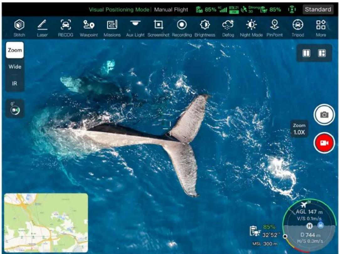
Fig 6-15 "Zoom Camera" Interface
■ Adjust the Zoom Factor
When shooting, tap the "Zoom" dynamic icon, and the zoom factor setting window will pop up. A maximum of 560x hybrid zoom is supported. You can drag up and down or tap the number on the left to set the zoom factor according to your needs to zoom in and out on the shooting picture, so as to flexibly shoot objects at different distances.
■ Camera Settings
Tap the "©" icon to enter the "Camera Settings" interface and perform relevant settings. For more information, see "6.8.1 Camera Function Area" in this chapter.

Note
- The zoom lens of the DG-L35T gimbal camera has the function of automatically switching shooting modes. It will trigger the night vision mode when the ambient light intensity is between 5\~10lux (i.e. in a dark light environment).
6.8.3 "Thermal Camera" Interface
On the main interface of the Autel Enterprise App, tap the " ” icon in the corner of the "Thermal Camera" preview interface, or tap the " ” icon after entering the "Zoom Camera" interface or "Wide Angle Camera" interface, to enter the "Thermal Camera" full-screen interface.

Fig 6-16 "Thermal Camera" Interface
Table 6-9 "Thermal Camera" Interface Details
| No. | Icon | Meaning | Description |
| 1 | Thermal Color | Tap this icon, and the drop-down list of “Thermal Color” pops up. You can scroll up and down in the list to select a color palette. | |
| 2 | -20-150 Mode | Radiometric Measurement Mode | High gain mode (-20°C to 150°C), which enables more accurate radiometric measurement. |
| 3 | 0-550 Mode | Radiometric Measurement Mode | Low gain mode (0°C to 550°C), which has a larger radiometric measurement range. |
| 4 | FFC | FFC Calibration | Flat-Field Calibration. After calibration, the image quality of thermal imaging will be optimized, and temperature changes will be easier to observe. |

Warning
- While shooting, do not aim the infrared thermal imaging camera at strong energy sources such as the sun, lava, laser beams, and molten metal, to avoid damaging the infrared detector.
- The temperature of the measured target should be within 600^ . Over-temperature measurements can cause burns and damage to the infrared detector.
■ Set Thermal Color
After tapping the " 🔊" icon, you can scroll up and down in the pop-up drop-down list to select a color palette.
➢ After selection, the images from the thermal camera will be displayed in the color style of the selected color palette.
■ Set Infrared Shooting
Tap the "©" icon to enter the "Camera Settings" interface and perform relevant settings. For more information, see "6.8.1 Camera Function Area" in this chapter.
■ Set Radiometric Measurement Mode
Tap the " -20-150 Mode " icon or the " 0-550 Mode " icon to switch between radiometric measurement modes.
➢ High gain mode (-20°C to 150°C): This mode has higher radiometric measurement accuracy but a smaller radiometric measurement range compared with the low gain mode.
Low gain mode (0°C to 550°C): This mode has a larger radiometric measurement range but lower radiometric measurement accuracy compared with the high gain mode.
■ FFC Calibration
Tap the "FFC" icon to enable the FFC calibration function.

Note
- The radiometric measurement mode and FFC calibration functions can be used only after the infrared radiometric measurement function is enabled in the camera settings.
■ Adjust the Infrared Zoom Factor
While shooting, tap the "1.0x" dynamic icon, and the infrared zoom factor setting window will pop up. You can drag up or down to zoom in or out on the picture captured by the thermal camera, so as to flexibly shoot objects at different distances.

Tip
● The thermal camera of DG-L35T Gimbal support up to 16x digital zoom.
6.8.4 "Wide Angle Camera" Interface
On the main interface of the Autel Enterprise App, tap the "⚡" icon in the corner of the "Wide Angle Camera" preview interface, or tap the "Wide" icon after entering the "Zoom Camera" interface or "Thermal Camera" interface, to enter the "Wide Angle Camera" full-screen interface.
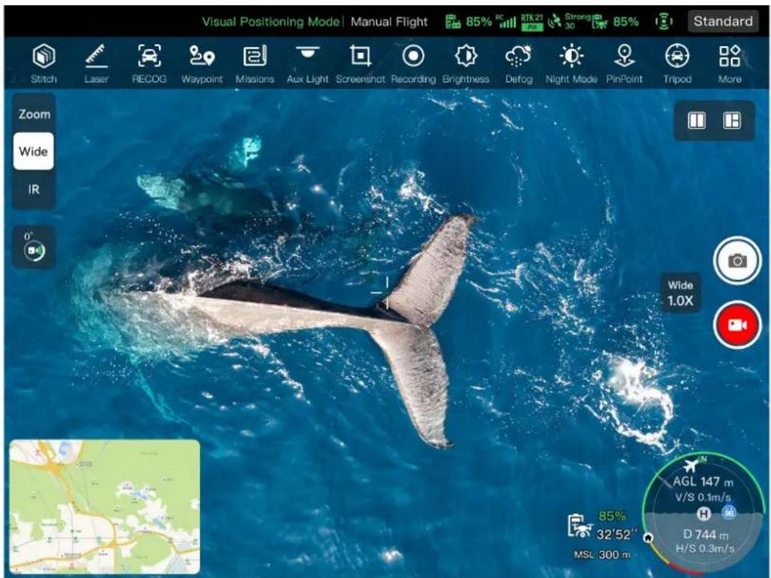
Fig 6-17 "Wide Angle Camera" Interface
■ Adjust the Wide Angle Zoom Factor
While shooting, tap the "1.0x" dynamic icon, and the wide angle zoom factor setting window will pop up. A maximum of 16x digital zoom is supported. You can drag up or down to zoom in or out on the picture captured by the wide angle camera, so as to flexibly shoot objects at different distances.
■ Camera Settings
Tap the "©" icon to enter the "Camera Settings" interface and perform relevant settings. For more information, see "6.8.1 Camera Function Area" in this chapter.
6.9 Flight Missions
Flight missions are divided into waypoint missions, rectangle missions, and polygon missions in terms of type. You can tap the corresponding icon in the shortcut toolbar or toolbox to enter the relevant mission editing interfaces.
Important
If any of the following conditions are detected, the flight mission will end automatically, and the aircraft will perform other operations according to the following conditions:
- Low battery power: A notification will pop up on the Autel Enterprise App to inform you that the aircraft will return to the home point automatically.
- Critically low battery power: The aircraft will end its mission and automatically land at its current position.
- During a flight mission, if the remote controller is powered off, the aircraft will execute the lost action that you set.

Tip
- When the aircraft is in visual positioning mode, it cannot execute waypoint missions, rectangle missions, or polygon missions.
6.9.1 Waypoint
In the shortcut toolbar (or Shortcuts), tap the "💡" icon to enter the "Waypoint" mission interface. You can add multiple waypoints on the map. Every two neighboring waypoints connect to form a flight segment and one or more flight segments form a route. By setting the flight altitude, flight speed, camera action, and waypoint actions of each waypoint for each route and each waypoint, the aircraft will automatically fly according to the route and perform corresponding actions at each waypoint.

Fig 6-18 Waypoint

Fig 6-19 Waypoint Mission in Progress
Table 6-10 "Waypoint Mission" Terms and Details
| Term | Definition |
| Relative Height | Refers to the vertical height of the aircraft relative to the take-off point. |
| Altitude | Refers to the vertical height of the aircraft relative to sea level. |
| Yaw Angle | It is used to set the position where the nose of the aircraft is facing. The default is to follow the route. When the point of interest has been added, it is often set in conjunction with the point of interest, that is, the yaw angle of the aircraft is set to turn to the point of interest. |
| Gimbal pitch | The observable range of the gimbal camera, that is, the angle from the top to the bottom (0° ~ 90°). |
| Finish Action | Refers to the actions that the aircraft will perform after finishing the waypoint mission. |
| Lost Action | Refers to the actions that the aircraft will perform when disconnected from the remote controller for more than 4 seconds during flight. |
| Segment Action | Refers to the actions performed by the camera, the gimbal, and the aircraft during the flight segment formed between the current waypoint and the next waypoint. |
Waypoint Action
Refers to the actions performed by the camera, gimbal, and aircraft at a specific waypoint.
Table 6-11 "Waypoint Mission" Icons and Details
| No. | Icon | Meaning | Description |
| 1 |  | Waypoint Settings | Tap this icon to add a waypoint on the map as needed.Every two neighboring waypoints connect to form a flight segment and one or more flight segments form a route. |
| 2 |  | POI Settings | Tap this icon to add a point of interest on the map as needed. |
| 3 | [T8S2] | Heading Switch | Tap this icon, and the starting point and ending point of the whole route will change direction. |
| 4 |  | Delete | When the aircraft is in waypoint setting status, tapping this icon once will delete the latest waypoint but cannot delete points of interest.When the aircraft is in POI setting status, tapping this icon once will delete the latest point of interest but cannot delete waypoints. |
| 5 |  | Clear | Tap this icon and then tap the "Confirm" button to clear all waypoints and POIs. |
| 6 |  | Save Route | Tap this icon, and the currently edited waypoint mission will be saved to "Mission". |
| 7 |  | Edit Route | Tap this icon to edit the saved route missions. |
| 8 |  | Execute Mission | Tap this button, and the aircraft will enter the "Pre-flight Check" interface. After the check is completed, the aircraft will take off to perform the waypoint mission. |
| 9 |  | Pause Mission | When executing a waypoint mission, tap this icon, and the aircraft will pause the waypoint mission and hover at the current position. |
| 10 |  | Exit Mission | Tap this icon, and the aircraft will abort the current waypoint mission and automatically return. |
■ Add Waypoints
On the waypoint mission interface, tap the “💡” icon, find the starting point for the mission on the map and tap it to create the first waypoint, and then repeat the previous operation to create multiple waypoints as required.
When adding waypoints, the waypoint mission settings interface will pop up on the right side of the waypoint mission interface.
| Tip |
| ● A route must include at least two waypoints: a starting point ( Ⓤ ) and an ending point ( Ⓔ ).● To set a waypoint position more precisely, you can enter the waypoint coordinates under "Waypoint Coordinates" on the waypoint settings interface. |
Tap the "💡" icon in the upper-right corner of the waypoint settings interface to enter the route settings interface.
Tap the waypoint icon on the right side of the waypoint settings interface to enter the corresponding waypoint settings interface.
■ Set Route Name and Route Altitude Type
On the route settings interface:
Tap the "Route Name" edit box and enter the name as required to set the name of a route.
Tap the drop-down list of "Route Altitude Type" and select "AGL" or "MSL" to set the altitude type of the entire route.
■ Set Flight Altitude
In the "Flight Altitude" edit box on the route settings interface, directly enter the flight altitude value or tap the shortcut buttons on the left and right sides to adjust the integer value. This way, you set the flight altitude of the entire route.
On the waypoint settings interface, the flight altitude is set to "Align Route" by default. After deselecting "Align Route", in the "Flight Altitude" edit box, directly enter the flight altitude value or tap the shortcut buttons on the left and right sides to adjust the value. This way, you set the flight altitude of the aircraft at the current waypoint.
| Tip |
| ● The maximum value for the flight altitude setting will be dynamically adjusted according to the altitude limit set in the "Flight Control Parameter Setting". |
■ Set Flight Speed
In the "Flight Speed" edit box on the route settings interface, directly enter the flight speed value or move the slider below left or right to adjust the value. This way, you set the flight speed of the entire route.
On the waypoint settings interface, the flight speed is set to "Align Route" by default. After deselecting "Align Route", in the "Flight Speed" edit box, directly enter the flight speed value or move the slider below left or right to adjust the value. This way, you set the flight speed of the aircraft at the current waypoint.

Tip
● The flight speed setting ranges from 1 to 10 m/s.

Note
- After take-off, the aircraft will gradually adjust its "flight altitude" and "flight speed" to the set values while flying to this waypoint.
■ Set Yaw Angle
On the route settings interface, tap the drop-down list of "Yaw Angle" to set the yaw angle of the aircraft in the entire route to "Route Following", "Manual", or "Custom".
On the waypoint settings interface, the yaw angle of the aircraft is set to "Align Route" by default. After deselecting "Align Route", tap the drop-down list of "Yaw Angle" to set the yaw angle of the aircraft at the current waypoint to "Route Following", "Manual", "Custom", or "Turn to Point of Interest" (the waypoint should be associated with the point of interest).
Route Following: If it is set to "Route Following", the nose of the aircraft will follow the direction of the waypoint change, that is, turn from the current waypoint to the next waypoint according to the set route.
➢ Manual: If it is set to "Manual", you need to use the remote controller to control the nose direction of the aircraft during the flight.
Custom: If it is set to "Custom", the "Yaw Angle (0°-360°)" setting item will be displayed. You can directly enter the value or tap the shortcut buttons on the left and right sides to adjust the value. After setting, the aircraft nose will be adjusted according to the set value.
➢ Turn to Point of Interest: If it is set to "Turn to Point of Interest", the nose of the aircraft will always face the set POI during the flight segment where the yaw angle of the aircraft is set to "Turn to Point of Interest" when the waypoint mission is executed.
■ Set Obstacle Avoidance Mode
On the route settings interface, the obstacle avoidance mode can be set to "Bypass" or "Off". ➢ If "Bypass" is selected, the aircraft will automatically bypass obstacles.

Warning
- If the obstacle avoidance mode is turned off, the obstacle avoidance system of the aircraft will not be enabled. In this case, please try to choose an open area to control the aircraft.
■ Set Camera Action
On the route settings interface, tap the drop-down list of "Camera Action" to set the camera action of the entire route to "Start Recording", "Stop Recording", "Shoot", "Stop Shooting", "Timelapse", "Distance Lapse", and "No Action".
On the waypoint settings interface, the segment action is set to "Align Route" by default. After deselecting "Align Route", tap the drop-down list of "Camera Action" to set the camera action of the current flight segment to "Start Recording", "Stop Recording", "Shoot", "Stop Shooting", "Timelapse", "Distance Lapse", and "No Action".
When it is set to "Timelapse", the "Photo Interval" will be displayed. At this time, you can move the slider left or right to adjust the value.
When it is set to "Distance Lapse", the "Photo Distance" will be displayed. At this time, you can move the slider left or right to adjust the value.
■ Set Gimbal Pitch Angle
On the route settings interface, enter the value in the edit box to the right of "Gimbal Pitch Angle (0°-90°)", or move the slider below left or right to adjust the gimbal pitch angle of the entire route. On the waypoint settings interface, the gimbal pitch angle (segment action) is set to "Align Route" by default. After deselecting "Align Route", enter the value in the edit box to the right of "Gimbal Pitch Angle (0°-90°)", or move the slider below left or right to adjust the gimbal pitch angle of the current segment.
■ Add a Waypoint Action
On the waypoint settings interface, tap the "Add Action +" button under "Waypoint Action" to set the camera action, gimbal pitch angle, and yaw angle for the current waypoint. You can add a maximum of 10 waypoint actions for one waypoint.
■ Set Finish Action
On the route settings interface, tap the drop-down list of "Finish Action" to set the flight action of the aircraft after completing the waypoint mission.
If "Auto RTH" is selected, the aircraft will automatically return to the starting point after completing the mission.
If "Hovering" is selected, the aircraft will hover at the end point after completing the mission.
■ Set Signal Loss Action
On the route settings interface, tap the drop-down list of "Signal Loss Action" to set the flight action of the aircraft after losing connection with the remote controller for 4 seconds.
If "Continue" is selected, the aircraft will continue to execute the mission and perform the "Finish Action" after completing the mission.
If "Auto RTH" is selected, the aircraft will automatically return to the starting point.
■ Set Waypoint Coordinates
After adding a waypoint, you can automatically obtain the longitude and latitude parameters of the waypoint. You can also manually enter and modify the longitude and latitude of the waypoint.
Under "Waypoint Coordinates" on the waypoint settings interface, the waypoint coordinates can be set in two formats: DD (Decimal Degrees) and DMS (Degrees Minutes Seconds). Tap the "Longitude" and "Latitude" edit boxes below and enter the longitude and latitude of the waypoint to complete the modification of the waypoint coordinates.
When using the DD (Decimal Degrees) format, you can use the arrow keys located on the right side of the editing field to make fine adjustments to the longitude and latitude.
Table 6-12 Fine Adjustment of Latitude and Longitude
| Parameter Type | Tap Up Arrow | Tap Down Arrow | Tap Left Arrow | Tap Right Arrow |
| Longitude | / | / | -0.000005 | +0.000005 |
Latitude +0.000005 -0.000005 / /
■ Add Point of Interest
On the waypoint mission interface, tap the "★" icon, find the specific location on the map where the POI needs to be set and tap it to create the first POI, and then repeat the previous operation to create multiple POIs as required.
When adding POIs, the POI setting interface will pop up on the right side of the waypoint mission interface.
■ Set POI Altitude
On the POI settings interface, you can set the POI altitude. POI altitude refers to the altitude of the point of interest relative to the take-off point. In the "Altitude (0-800m)" edit box, directly enter the altitude value of the point of interest or tap the shortcut buttons on the left and right sides to adjust the value to set the POI altitude.

Important
- When the point of interest is higher than the waypoint, the gimbal camera cannot look at the point of interest above.
■ Set Associated Waypoints
On the POI settings interface, tap the waypoints to be associated under "Link Waypoint(s)" to associate the current point of interest with the selected waypoints. To associate all waypoints, check the "Select All" box on the right side.
After a waypoint is associated with a point of interest, the yaw angle of the aircraft at the waypoint will not be set to "Align Route" by default. If the "Yaw Angle" of the aircraft at the waypoint is set to "Turn to Point of Interest", the nose of the aircraft will always face the associated point of interest during the flight segment from this waypoint to the next waypoint when the waypoint mission is executed.
■ Start Pre-flight Check
After the completion of all settings for a route, relevant flight mission data will be synchronously displayed at the bottom center of the waypoint mission interface, including the route length, estimated time, waypoints, and photos to be taken. Tap the “✗” icon on the left side to enter the "Pre-flight Check" interface.
■ Upload a Route and Start a Mission
After completing the pre-flight check, press the "Slide to takeoff" icon at the bottom of the "Pre-flight Check" interface, and the aircraft will automatically take off to execute the mission. The estimated completion time, current photo count, current altitude, current wind speed, and other basic information will be synchronously displayed at the bottom center of the waypoint mission interface. The lower-left small screen displays the current view observed by the gimbal camera. Tap to enlarge it to full screen for viewing.
When the aircraft completes the waypoint mission, the relevant flight mission data of this route will be displayed at the bottom center of the map, including the route length, estimated time, waypoint, the number of photos taken, and the number of flights.
6.9.2 Rectangle Mission
In the shortcut toolbar (or Shortcuts), tap the " 🔊" icon to enter the "Rectangle" mission interface. You can add a rectangular area on the map and perform operations such as dragging, scaling, and rotating to adjust the position and size of the area. After adjustments, the Autel Enterprise App will automatically generate a continuous series of equidistant flight routes within the rectangular area based on the side overlap and course angle settings. The aircraft will then
automatically fly to execute the shooting mission according to these flight routes and relevant settings.

Fig 6-20 Rectangle Mission

Fig 6-21 Rectangle Mission in Progress
Table 6-13 "Rectangle Mission" Terms and Details
| Term | Definition |
| Relative Height | Refers to the vertical altitude of the work surface of the shot object relative to the take-off point of the aircraft. |
| GSD | Ground Sampling Distance. |
| Finish Action | Refers to the action that the aircraft will perform after completing a rectangle mission. |
| Lost Action | Refers to the actions that the aircraft will perform when disconnected from the remote controller for more than 4 seconds during flight. |
| Front Overlap | Refers to the image overlap rate between two consecutive photos taken when capturing images along the flight heading. |
| Side Overlap | Refers to the image overlap rate between two consecutive photos taken when capturing images along two adjacent flight routes. |
| Main Course Angle | Refers to the course angle between the main route and the latitude line (horizontal line) when the flight routes are automatically generated. |
| Gimbal pitch | The observable range of the gimbal camera, that is, the angle from the top to the bottom (-30° ~ 90°). |
| Coordinated Turns | When enabled, the aircraft will switch from one main route to an adjacent main route along the optimal arc-shaped path. |
Table 6-14 "Rectangle Mission" Icons and Details
| No. | Icon | Meaning | Description |
| 1 |  | Clear | Tap this button, and then tap the "Confirm" button in the pop-up window to reset the rectangle mission. |
| 2 |  | Save Route | Tap this icon, and the currently edited rectangle mission will be saved to "Mission". |
| 3 |  | Edit Route | Tap this icon to edit the saved rectangle mission. |
| 4 |  | Execute Mission | Tap this button, and the aircraft will enter the "Pre-flight Check" interface. After the check is completed, the aircraft will take off to perform the rectangle mission. |
| 5 |  | Pause Mission | When executing a rectangle mission, tap this icon, and the aircraft will pause the rectangle mission and hover at the current position. |
6

Exit Mission
Tap this icon, and the aircraft will abort the current rectangle mission and automatically return.
■ Add a Rectangular Area
On the map of the rectangle mission interface, find the center point of the mission to be executed and tap it to automatically generate a rectangular area. You can adjust the area of the rectangle by dragging the eight white points at the edges of the rectangle. You can drag the "cross arrow" in the center of the rectangle to move the rectangle or drag the "curved arrow" on both sides of the rectangle to rotate the rectangle around the center point.
When adding a rectangular area, the rectangle mission settings interface will pop up on the right side of the rectangle mission interface.

Tip
- A rectangular area includes two waypoints, that is, the starting point ( ) and the end point ( )
■ Set Mission Name
On the rectangle mission settings interface:
Tap the "Mission Name" edit box and enter the name as required to set the name of a rectangle mission.
■ Set Flight Altitude and Relative Height
In the "Flight Altitude (20-800m)" edit box on the rectangle mission settings interface, directly enter the flight altitude value or tap the shortcut buttons on the left and right sides to adjust the value. This way, you set the flight altitude of the rectangle mission.
The setting range of "Relative Height" will automatically be dynamically adjusted according to the flight altitude setting. In the edit box, directly enter the mission altitude value or tap the shortcut buttons on the left and right sides to adjust the value. This way, you set the relative altitude of the rectangle mission.

Tip
- The maximum value for the flight altitude setting will be dynamically adjusted according to the altitude limit set in the "Flight Control Parameter Setting".
● GSD varies with different flight altitude values.
■ Set Flight Speed
In the "Flight Speed" edit box on the rectangle mission settings interface, directly enter the flight speed value or move the slider below left or right to adjust the value. This way, you set the flight speed of the rectangle mission.

Tip
● The flight speed setting ranges from 1 to 10 m/s.
■ Set Obstacle Avoidance Mode
On the rectangle mission settings interface, the obstacle avoidance mode can be set to "Bypass" or "Off".
If "Bypass" is selected, the aircraft will automatically bypass obstacles.
| Warning |
| ● If the obstacle avoidance mode is turned off, the obstacle avoidance system of the aircraft will not be enabled. In this case, please try to choose an open area to control the aircraft. |
| Tip |
| ● When flying at a high altitude, if there are no obstacles, it is recommended to disable the obstacle avoidance mode. |
■ Set Finish Action
On the rectangle mission settings interface, tap the drop-down list of "Finish Action" to set the flight action of the aircraft after completing the rectangle mission.
If "Auto RTH" is selected, the aircraft will automatically return to the starting point after completing the mission.
If "Hovering" is selected, the aircraft will hover at the end point after completing the mission.
■ Set Signal Loss Action
On the rectangle mission settings interface, tap the drop-down list of "Signal Loss Action" to set the flight action of the aircraft after losing connection with the remote controller for 4 seconds.
If "Mission Continue" is selected, the aircraft will continue to execute the mission and perform the "Finish Action" after completing the mission.
If "Auto RTH" is selected, the aircraft will automatically return to the starting point.
■ Advanced Settings
On the rectangle mission settings interface, tap "Advanced Settings" to enter the advanced settings interface and set the front overlap, side overlap, main course angle, and gimbal pitch angle for the rectangle mission.
- Set Front Overlap In the "Front Overlap(%)" edit box on the advanced settings interface, directly enter the value or move the slider below left or right to adjust the value to set the front overlap of the rectangle mission.
- Set Side Overlap In the "Side Overlap(%)" edit box on the advanced settings interface, directly enter the value or move the slider below left or right to adjust the value to set the side overlap of the rectangle mission.
| Tip |
| ● The setting range of the front overlap and side overlap is 10%-90%, and the default value is 70%. |
- Set Main Course Angle
On the advanced settings interface, you can set the main course angle (0-359°) in two ways: "Custom" or "Auto".
If "Custom" is selected, you can directly enter the value or tap the shortcut digital buttons on the left and right sides to adjust the angle between the main route of the rectangle mission and the latitude line.
- Set Gimbal Pitch Angle
On the advanced settings interface, enter the value in the edit box to the right of "Gimbal Pitch Angle (-30°-90°)", or move the slider below left or right to adjust the gimbal pitch angle of the entire route.
■ Turn On/Off Elevation Optimization
If this function is turned on, the aircraft will create a route along the center point of the rectangle for re-shooting after completing the shooting of the main route. This helps optimize the overall shooting accuracy of the mission.
■ Turn On/Off Double Grid
If this function is turned on, the aircraft will change its heading by 90^ and shoot the rectangle mission area again after completing the shooting of the main route. The two routes have a 90^ overlap.
■ Turn On/Off Route Extension
Due to the limited gimbal pitch angle and flight altitude, some areas on the outer edges of the rectangle mission area might not be captured by the camera. In such cases, you need to turn on route extension to extend the rectangle mission area so as to ensure complete coverage of the target area.
■ Turn On/Off Coordinated Turns
After this function is turned on, the aircraft will follow the optimal arc-shaped path for turns when switching from one main route to an adjacent one.

Tip
- When the obstacle avoidance mode is set to "Bypass", the coordinated turns function does not take effect.
■ Start Pre-flight Check
After the completion of all settings for a rectangle mission, relevant flight mission data will be synchronously displayed at the bottom center of the rectangle mission interface, including the route length, mapping area, estimated time, and photos to be taken. Tap the “✗” icon on the left side to enter the "Pre-flight Check" interface.
■ Upload a Route and Start a Mission
After completing the pre-flight check, press the "Slide to takeoff" icon at the bottom of the "Pre-flight Check" interface, and the aircraft will automatically take off to execute the mission. The estimated completion time, current photo count, current altitude, current wind speed, and other basic information will be synchronously displayed at the bottom center of the rectangle mission interface. The lower-left small screen displays the current view observed by the gimbal camera. Tap to enlarge it to full screen for viewing.
■ Complete Route Missions
When the aircraft completes the rectangle mission, the relevant flight mission data of this route will be displayed at the bottom center of the map, including the route length, mapping area, estimated time, the number of photos taken, and the number of flights.
6.9.3 Polygon
In the shortcut toolbar (or Shortcuts), tap the "💡" icon to enter the "Polygon" mission interface. You can add a square area on the map and perform operations such as dragging, adding side boundaries, and dragging corner points to adjust the position and size of the area. After adjustments, the Autel Enterprise App will automatically generate a continuous series of equidistant flight routes within the polygonal area based on the side overlap and course angle settings. The aircraft will then automatically fly to execute the shooting mission according to these flight routes and relevant settings.

Fig 6-22 Polygon

Fig 6-23 Polygon Mission in Progress
Table 6-15 "Polygon Mission" Terms and Details
| Term | Definition |
| Relative Height | Refers to the vertical altitude of the work surface of the shot object relative to the take-off point of the aircraft. |
| GSD | Ground Sampling Distance. |
| Finish Action | Refers to the action that the aircraft will perform after completing a polygon mission. |
| Lost Action | Refers to the actions that the aircraft will perform when disconnected from the remote controller for more than 4 seconds during flight. |
| Front Overlap | Refers to the image overlap rate between two consecutive photos taken when capturing images along the flight heading. |
| Side Overlap | Refers to the image overlap rate between two consecutive photos taken when capturing images along two adjacent flight routes. |
| Main Course Angle | Refers to the course angle between the main route and the latitude line (horizontal line) when the flight routes are automatically generated. |
| Gimbal pitch | The observable range of the gimbal camera, that is, the angle from the top to the bottom (-30° ~ 90°). |
| Coordinated Turns | When enabled, the aircraft will switch from one main route to an adjacent main route along the optimal arc-shaped path. |
Table 6-16 "Polygon Mission" Icons and Details
| No. | Icon | Meaning | Description |
| 1 |  | Clear | Tap this button, and then tap the "Confirm" button in the pop-up window to reset the polygon mission. |
| 2 |  | Save Route | Tap this icon, and the currently edited polygon mission will be saved to "Mission". |
| 3 |  | Edit Route | Tap this icon to edit the saved polygon mission. |
| 4 |  | Execute Mission | Tap this button, and the aircraft will enter the "Pre-flight Check" interface. After the check is completed, the aircraft will take off to perform the polygon mission. |
| 5 |  | Pause Mission | When executing a polygon mission, tap this icon, and the aircraft will pause the polygon mission and hover at the current position. |
| 6 |  | Exit Mission | Tap this icon, and the aircraft will abort the current polygon mission and automatically return. |
■ Add a Polygonal Area
On the map of the polygon mission interface, find the center point of the mission to be executed and tap it to automatically generate a square area. You can tap the "+" icon between two white points to add side lines for the area. You can drag the white points to adjust the positions of the corner points of the polygon, which allows you to modify the area of the polygon. You can also drag the "cross arrow" in the center of the polygonal area to move the polygon.
When adding a polygonal area, the polygon mission settings interface will pop up on the right side of the polygon mission interface.

Tip
- A polygonal area includes two waypoints, that is, the starting point ( ) and the end point ( )
- For the settings of other operations for a polygon mission, see "6.9.2 Rectangle Mission" in this chapter.
6.9.4 Pre-flight Check
Before the aircraft starts to execute a mission, a pre-flight check is required. On the "Pre-flight Check" interface, you can preview the current status (such as battery level, battery temperature, and SD card memory) and route data of the aircraft and perform some settings such as flight parameters and obstacle avoidance settings.

Fig 6-24 Pre-flight Check for a Flight Mission
- On the ongoing flight mission interface, tap the "✗" icon on the left, and the "Pre-flight Check" interface will pop up. Please make sure that there is no fault or abnormal alarm, otherwise, you need to follow the tips to solve it.
- Confirm aircraft status and route preview data.
- According to different types of flight missions, set the corresponding flight parameters. If not set, the "RTH Altitude", "Distance Limit", "Altitude Limit", "Home Point Settings", and "Remote Controller" settings are based on general settings.
- Select to enable or disable obstacle avoidance.
- After completing the above operations, press the "Slide to takeoff" icon at the bottom of the interface.
6.9.5 Resume Mission
When an abnormal situation such as an abnormal exit occurs during a flight mission, tap the "☐" icon to enter the "Mission" interface. This will trigger the "Resume Mission" function, and a prompt window will pop up.
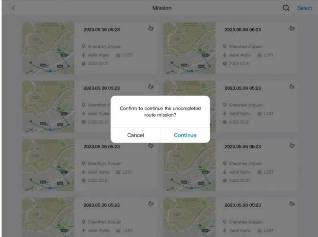
Fig 6-25 Resume Mission
■ Resume Mission Options
Tap the "Continue" button. The position where the aircraft stopped will be displayed, and the aircraft will fly to this position to continue the last mission.
Tap the "Cancel" button. After closing the pop-up window, the mission will no longer be executed from the last point.
6.9.6 Mission and Favorites
On the "Mission/Favorites" interface, you can query, edit, favorite, and delete previously saved flight missions.
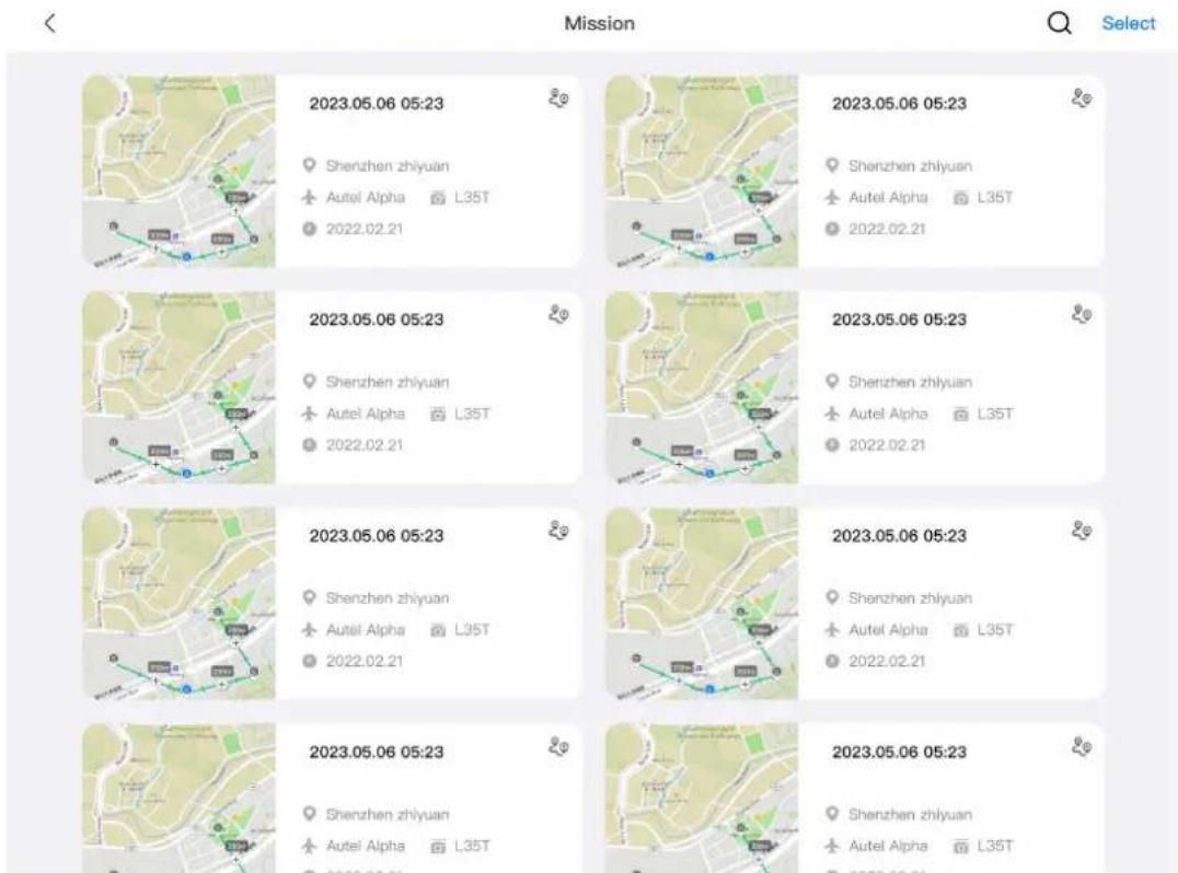
Fig 6-26 Mission/Favorites Interface
■ Query
Tap the “Q” icon in the upper-right corner of the “Mission” interface and enter the desired content to quickly locate the corresponding historical flight mission.
Edit
Tap a historical flight mission on the "Mission" interface to enter the waypoint mission editing interface. Tap the "√" icon to edit the flight mission.
- Favorite
Tap the "Select" button in the upper-right corner of the "Mission" interface, then single-select, multi-select, or select all the missions to be favored, and then tap the "☆" icon to complete the favoriting action. Favorited missions will be displayed on the "Favorites" interface for easy access.
Delete
Tap the "Select" button in the upper-right corner of the "Mission" interface, then single-select, multi-select, or select all the missions to be deleted, and then tap the "💡" icon. After a dialog box pops up, tap the "Confirm" button. This way, the selected flight missions are deleted.
6.9.7 Personal Center
Tap the “💡” icon (in the shortcut toolbar or Shortcuts) to enter the "Personal Center" interface. When using the product for the first time, you need to register and log in to the Autel Enterprise App.

Fig 6-27 "Personal Center" Interface
On the "Personal Center" interface, you can perform the following operations:
■ Query Flight Data
On the "Personal Center" interface, you can query the flight time, flight distance, and the number of flights.
■ Purchase "Autel Robotics Care"
On the "Personal Center" interface, you can purchase the "Autel Robotics Care" value-added service for your aircraft (within 48 hours of activation).
| Tip |
| ● If you do not register and log in to the Autel Enterprise App, you cannot use cloud-related functions.● You have the right to use a registered account, but the account ownership belongs to Autel Robotics. Please read the "User Agreement" carefully when registering. |
Chapter 7 Firmware Updates and Maintenance
In order to ensure the reliability and overall performance of the aircraft and relevant parts, as well as to obtain the best flight experience, the aircraft, remote controller, and parts need to be updated to the latest firmware version.
Use the Autel Enterprise App to perform firmware updates for the aircraft, remote controller, smart battery, and other parts.
Important
- Online updates require that the remote controller can access the internet.
7.1 Aircraft and Remote Controller Firmware Updates
- Power on the remote controller and aircraft. Make sure that the aircraft and remote controller are already paired, both have a battery level of more than 25%, and the network connection of the remote controller is normal.
- Open the Autel Enterprise App. If there is a version update available, you will receive a popup notification on the main interface of the App or you can manually select the update in the settings of the App.
- Tap "Update All", and the Autel Enterprise App will automatically download and update the firmware for the remote controller and aircraft.
- After the update is complete, follow the pop-up instructions to restart the remote controller and aircraft.
Important
- During the update process, do not power off the aircraft and keep it connected to the remote controller.
- The update process is expected to take about 15 minutes (depending on the network that the remote controller is connected to).
- Do not move the command sticks before and after the update to ensure that the propellers remain stationary.
- Make sure that the aircraft and remote controller have sufficient storage space for the firmware update packages.
- During the update process, the firmware of the smart battery MDH_10000_23700 will also be updated to the latest version.
7.2 Aircraft Parts Maintenance
To ensure the optimal performance of the aircraft, regular maintenance is required for the aircraft parts. For more information, see "Maintenance Manual". If you have any questions, please contact Autel Robotics After-Sales Support.
Table 7-1 Aircraft Consumable Parts List
| No. | Part | Quantity | Note |
| 1 | Propeller CW | 2 | |
| 2 | Propeller CCW | 2 | |
| 3 | Powered Motor 4 | Replacement only during deep maintenance (every 900 service hours/every 3 years). | |
| 4 | Rubber Protective Cover P-Port | 2 | |
| 5 | Rubber Protective Cover C-Port | 1 | |
| 6 | Rubber Protective Cover O-Port | 1 | |
| 7 | Rubber Protective Cover DEBUG | 1 | |
| 8 | Rubber Protective Cover SIM | 1 | |
| 9 | (Bottom Port) Rubber Protective Cover | 2 | |
| 10 | Air Inlet Dust Filter | 1 | |
| 11 | Air Outlet Dust Filter | 1 | |
| 12 | Remote Controller Sticks | 2 |
Table 7-2 User-replaceable Parts List
| No. | Part | Quantity | Part Number | Manufacturer |
| 1 | Left Front Arm Propeller CCW | 1 | EAN: 6924991131892UPC: 889520211895 | Autel Robotics |
| 2 | Right Front Arm Propeller CW | 1 | EAN: 6924991133391UPC: 889520213394 | Autel Robotics |
| 3 | Left Rear Arm Propeller CW | 1 | EAN: 6924991133407UPC: 889520213400 | Autel Robotics |
| 4 | Right Rear Arm Propeller CCW | 1 | EAN: 6924991133414UPC: 889520213417 | Autel Robotics |
| 5 Gimbal 1 | EAN: 6924991126195UPC: 889520206198 | Autel Robotics | ||
| 6 Smart Battery 2 | EAN: 6924991126201UPC: 889520206204 | Autel Robotics | ||

Tip
- You can independently contact Autel Robotics to purchase the aforementioned parts and follow the operation instructions for replacement.
- If the part that you want to replace is not listed in the above lists, please contact Autel Robotics. Failures caused by unauthorized disassembly and reassembly will not be covered by the warranty.
- For the service life of each part, see "Maintenance Manual".
7.3 Troubleshooting Guide

Tip
- The following troubleshooting measures are only limited to failures resulting from normal usage.
-
For failures resulting from abnormal usage, please contact Autel Robotics for handling.
-
The remote controller cannot power on:
-
Check whether the remote controller has sufficient power. If the battery level is too low, it may result in a power-on failure after shutdown. In this case, fully charge the remote controller and then power it on.
- Check whether the ambient temperature is suitable, as low temperatures can affect battery output performance, resulting in a power-on failure.
- If the remote controller was accidentally powered off during an update, it may not power on normally. In this case, contact Autel Robotics.
-
If the remote controller has not been subjected to external impacts, liquid submersion, or other destructive behaviors and does not have any conditions mentioned above, it may have a hardware failure. In such cases, contact Autel Robotics.
-
The aircraft cannot power on:
-
Check whether the smart battery has sufficient power. If the battery level is too low, it may result in a power-on failure after shutdown. In this case, fully charge the smart battery and then power the aircraft on.
- If the smart battery has sufficient power, check whether the battery makes proper contact with the aircraft's fuselage. Dirt or rust at the battery connector can lead to poor contact and must be cleaned before being re-inserted into the battery for power-on.
- Check whether there are any missing or damaged metal contacts at the aircraft battery connector and the smart battery connector. If yes, please contact Autel Robotics.
- Check whether the ambient temperature is suitable, as low temperatures can affect battery output performance, resulting in a power-on failure.
- If the aircraft or the smart battery is unexpectedly powered off during a firmware update, it may result in a power-on failure. In this case, contact Autel Robotics.
-
When none of the above conditions apply, if the aircraft can power on after the smart battery is replaced, it may be a hardware failure of the smart battery; if the aircraft still cannot power on after the smart battery is replaced, it may be a hardware failure of the aircraft itself. In this case, contact Autel Robotics.
-
The aircraft reports a fault during startup self-check:
-
Check the gimbal camera. If the gimbal camera has no response, power off the aircraft, reassemble the gimbal camera, and then perform a startup self-check again.
-
If the gimbal camera successfully passes the self-check, but the aircraft still reports a fault, it may be a hardware failure of the aircraft. In this case, contact Autel Robotics.
-
There is no response from the remote controller when pairing it with the aircraft:
-
Confirm that the distance between the aircraft and the remote controller is within 50 centimeters.
-
Check whether there is a metal object, mobile device, signal interference device, or another remote controller nearby.
-
After the aircraft powers on, the motors do not start:
-
Check whether the remote controller is paired with the aircraft.
- Please confirm whether the arms are fully unfolded. The motors will not be powered if the arms are not fully unfolded.
- Check whether the command sticks of the remote controller are functioning correctly and whether the remote controller has been correctly calibrated.
- Check whether the aircraft's battery has sufficient power.
- Check whether the aircraft's compass has been correctly calibrated.
-
If none of the above conditions apply, it may be a hardware failure of the aircraft itself. In this case, contact Autel Robotics.
-
After the motors start, the aircraft does not take off:
-
Check whether the aircraft is in a No-Fly Zone.
- Check whether the aircraft is placed on a flat surface.
- Check whether there are obstacles near the aircraft and whether the obstacle avoidance system of the aircraft is enabled.
-
Please confirm that all smart batteries are installed, and the battery level difference between the two batteries is less than 12%.
-
The aircraft has shortened flight time:
-
During flight, factors such as low ambient temperatures, flying against the wind, air turbulence, and carrying a mount all may lead to a shortened operating time of the aircraft.
● Make sure that the smart battery has fewer than 200 cycles. During the normal use of the smart battery, the battery capacity naturally decreases over time. -
The remote controller has unstable image transmission (e.g., image lag, image loss, or frequent disconnection):
-
Check whether the remote controller's antennas are securely connected and whether they are adjusted to an appropriate direction.
- Check whether there is any strong magnetic field or signal interference source near the aircraft and remote controller.
-
Confirm that the distance between the aircraft and the remote controller falls within the effective communication range and promptly reduce the flight radius if needed.
-
The gimbal camera automatically turns off during recording:
-
Do not immediately remove the microSD card from the gimbal. Instead, restart the camera and wait for the video file to be stored as much as possible.
- Check whether the memory of the microSD card is full; if it is, replace it with a new microSD card or transfer the media files.
-
Check whether the gimbal camera is securely connected to the aircraft. If the gimbal camera is not securely locked during installation, it may become loose due to flight vibrations, leading to poor contact and thus malfunctions.
-
When the aircraft is flying beyond the visual line of sight, image transmission fails:
- Enable auto-return to let the aircraft return to the home point.
-
What precautions should I follow when using the omnidirectional visual sensing system?
-
Before flying, make sure that the visual sensing camera lens is clean and not blocked ("Omnidirectional" means that the system can sense objects in six directions, including front, rear, left, right, up, and down).
- When flying, pay attention to the surrounding environment and safety prompt messages of the Autel Enterprise App.
-
Obstacles can be detected by checking the texture of their surfaces. The detection function cannot work properly for objects with no texture, repeated texture, a surface of pure color, moving objects, or tiny objects. It also cannot work properly in a strong light or weak light environment.
-
The accurate landing/landing protection function cannot work properly:
-
The accurate landing function can be implemented by the visual sensing lens on the rear of the aircraft. The camera detects the ground texture when the aircraft takes off or lands.
-
However, if the ground does not have any texture or the visual sensing lens on the rear of the aircraft is damaged, this function cannot work properly.
-
The omnidirectional visual sensing system cannot work properly:
-
Restart the aircraft and check whether the system can work properly this time.
-
Check whether the ambient light illuminance is suitable for the operation of the visual sensing system.
-
When recording video during flight, the image tilts:
-
Place the aircraft horizontally and keep it stationary. Use the "Gimbal Calibration" function in the Autel Enterprise App to calibrate the gimbal.
-
If the problem persists, adjust the gimbal according to the instructions described in the "Gimbal Adjustment" section.
-
The camera lens of the aircraft is dirty:
- Gently wipe the lens with a lens cleaning cloth. It is recommended to use the lens cleaning cloth provided in the rugged case.
-
The aircraft or remote controller experiences unexpected shutdown during firmware updates:
-
Restart the device. If it can power on normally, make sure that the device is sufficiently charged before proceeding with the update.
-
If the device cannot power on, contact Autel Robotics.
-
Restore the factory setting of the remote controller:
- Tap the "Maxitools" app on the main interface of the remote controller to perform a factory reset. Please back up important data before performing this operation.
-
Forcefully restart the remote controller after lag:
-
Press and hold the power button on the top of the remote controller for more than 6 seconds to forcefully power off the remote controller.
- Restarting the remote controller during flight will trigger the lost action of the aircraft.
Appendix A Product Specifications
A.1 Aircraft
| Aircraft | |
| Autel Alpha Empty Weight | 5420 g (Smart battery, propellers included) |
| Autel Alpha Weight | 6340 g (Smart battery, gimbal and propellers included) |
| Autel Alpha Maximum Take-Off Mass (MTOM) | 8400 g |
| Fuselage Dimensions | 1205×980×278 mm (unfolded, incl. propellers)780×568×278 mm (unfolded, excl. propellers)455×263×248 mm (folded, excl. propellers) |
| Diagonal Wheelbase Diagonal: 814 mm | |
| Propeller Dimension | 19inches |
| Propeller weight | 60 g |
| Maximum Propeller Rotational Speed | 6000 RPM |
| Maximum Ascent Speed | Slow: 3 m/sSmooth: 5 m/sStandard: 6 m/sLudicrous: 15 m/s |
| Maximum Descent Speed | Slow: 3 m/sSmooth: 5 m/sStandard: 6 m/sLudicrous: 10m/s |
| Maximum Horizontal Flight Speed(Windless Near Sea Level) | Slow: 3 m/sSmooth: 10 m/sStandard: 15 m/s (forward & backward), 10 m/s (sidewards)Ludicrous: 25 m/s (forward & backward & sidewards) |
| Maximum Service Ceiling Above Sea Level | 4500 meters |
| Maximum Flight Altitude | 800 meters (Altitude limit in the App) |
| Maximum Flight Time(Windless, Speed: 10.5 m/s) | 40 minutes |
| Maximum Range | 30 km (with carbon fiber propeller)27.5km (with injection molded propeller) |
| Maximum Hovering Time(Windless) | 38minutes |
| Maximum Wind Resistance | 12 m/s |
| Maximum Tilt Angle | Slow: 10°Smooth: 30°Standard: 30°Ludicrous: 36° |
| Maximum Angular Velocity | Pitch axis: 300°/sHeading axis: 120°/s |
| Operating Temperature | -20°C to 50°C |
| Hot-swappable Batteries | Supported |
| IP Rating | IP55 |
| Strobe | Integrated |
| Mid-flight Sensing | ADS-B receiver. UAT and 1090ES are supported. |
| GNSS | GPS+Galileo+BeiDou+GLONASS |
| Hovering Accuracy | Vertically±0.1 m (when visual positioning works normally)±0.3 m (when GNSS works normally)Horizontally±0.15 m (when visual positioning works normally)±0.3 m (when GNSS works normally) |
Image Transmission
| Operating Frequency | 900M: 902 - 928 MHz*2.4G: 2.400 - 2.476GHz**, 2.400 - 2.4835 GHz5.1G: 5.15 - 5.25 GHz, 5.17 - 5.25 GHz***5.8G: 5.725 - 5.829GHz**, 5.725 - 5.850 GHz* Only applicable to FCC regions.* *Only applicable to SRRC regions.*** Only applicable to CE & UKCA regions. |
| Note: Some frequencies are only available in some regions or for indoor use only. Check local laws and regulations for details. | |
| Maximum Transmission Distance(Without Interference and Blocking) | FCC: 20kmCE: 8km |
| Effective Isotropic Radiated Power (EIRP) | 900M:≤30dBm (FCC)2.4G:≤30dBm (FCC), ≤20dBm (CE/SRRC)5.1G:≤30dBm (FCC), ≤23 dBm (CE)5.8G:≤30dBm (FCC/SRRC), ≤14dBm (CE) |
| Visual Sensing System | |
| Sensing Range | Forward: 0.2 - 31 mBackward: 0.2 - 26 mSidewards: 0.5 - 45 mUpward: 0.2 - 45 mDownward: 0.2 - 45 m |
| FOV | Forward & Backward:90°(H), 90°(V)Sidewards:90°(H), 90°(V)Upward:90°(H), 90°(V)Downward:90°(H), 90°(V) |
| Operating Environment | Forward, backward, sidewards, and upward:The surface has rich textures, under a sufficient lighting environment (>15 lux, normal indoor fluorescent lighting environment).Downwards:The surface is a diffuse material with a reflectivity >20% (walls, trees, humans, etc.), under a sufficient lighting environment (>15 lux, normal indoor fluorescent lighting environment). |
| Millimeter-wave Radar Sensing System | |
| Operating Frequency | 60 - 64 GHz/24.0 - 24.25 GHz |
| Effective Isotropic Radiated Power (EIRP) | 60 - 64 GHz:≤20dBm (CE/FCC), ≤13dBm (MIC)24.0 - 24.25 GHz:≤20dBm (KC) |
| Sensing Range | 60G radar:Upward: 0.3 - 20 mDownward: 0.15 - 40 mForward & Backward: 0.3 - 30 mSidewards: 0.3 - 30 m24G radar:Downward: 0.8 - 20 m |
| FOV | Horizontal (6dB): ±35°/±22° (60 GHz/24 GHz)Vertical (6dB): ±30°/±20° (60 GHz/24 GHz) |
| Operating Environment | 60G millimeter-wave radar sensing system:Supports all-weather obstacle avoidance for glass, water, wires, buildings, and trees in 6 directions. Its obstacle avoidance distance varies with the obstacle's ability to reflect electromagnetic waves and its surface size.24G millimeter-wave radar sensing system:Supports downward sensing, and its sensing range varies by the ground material. For example, the sensing range of cement ground is 20 meters, and the sensing range of grass with a thickness of more than 3 cm is less than 10 meters. |
| Aircraft Version Limitations* | In order to comply with the regulations of the country or region where the target market is located, aircraft bottom millimeter-wave radars in some markets use the 24G frequency band, and the five directions of front, rear, left, right, and top use the 60G frequency band.Among them, the 24G version of the aircraft has turned off the 60G radar function in the five directions of front, rear, left, right, and top in the flight control software before leaving the factory, and only turned on the bottom 24G radar for assisted landing.The 24G version of the aircraft only supports visual obstacle avoidance under good lighting conditions and does not support the millimeter-wave radar obstacle avoidance function at night. |
Millimeter-wave Radar Sensing System
Radar and Visual Sensing Systems
| Sensing Range | Forward & Backward: 0.2 - 31 mSidewards: 0.2 - 45 mUpward: 0.2 - 26 mDownward: 0.15 - 50 m (60GHz radar) |
| FOV | Forward & Backward: 90°(H), 90°(V)Sidewards: 90°(H), 90°(V)Upward: 90°(H), 90°(V)Downward: 90°(H), 90°(V) |
| Operating Environment | Forward, backward, upward, and downward:Supports all-weather obstacle avoidance for various conditions, including water, forests, buildings and high voltage lines. At least one of the two conditions should be met:sufficient lighting or the obstacle has a strong reflection ability to electromagnetic waves.Sidewards:The surface has rich textures, under a sufficient lighting environment (>15 lux, normal indoor fluorescent lighting environment). |
A.2 Gimbal Camera
| Technical Specifications | |
| Gimbal Model | DG-L35T |
| Dimension | 144.7×133.3×158.4 mm |
| Weight | 920g |
| IP Rating | IP55 |
| Installation | Detachable (E-shape design) |
| Operating Temperature | -20°C to +50°C |
| Storage Temperature | -30°C to +70°C |
| Compatible Model | Autel Alpha, Autel Titan |
| Data Storage | Support microSD |
| Max. Expandable Memory 256GB | |
| Recommended Memory Card List | UHS-I Speed Class U3 or V30, minimum write speed 30MB/s |
| Gimbal | |
| Mechanical Range | Pitch: -135° to 45°Roll: -60° to 60°Yaw: -90° to 90° |
| Controllable Range | Pitch: -90° to 30° |
| Stable system | 3-axis mechanical gimbal (pitch, yaw, roll) |
| Max Control Speed (pitch) | 100°/s |
| Angular Vibration Range | <0.005° |
| Wi-Fi | |
| Wi-Fi Protocol | 802.11a/b/g/n/ac/ax, Support 2 x 2 MIMO Wi-Fi |
| Wi-Fi Operating Frequency | 2.4G: 2.400 - 2.476GHz*, 2.400 - 2.4835 GHz5.1G: 5.15 - 5.25 GHz5.8G: 5.725 - 5.829GHz*, 5.725 - 5.850 GHz*Only applicable to SRRC regions.Note: Some frequencies are only available in some regions or for indoor use only. Check local laws and regulations for details. |
| Wi-Fi Transmitter Power (EIRP) | 2.4G:≤30dBm (FCC), ≤20dBm (CE/SRRC)5.1G:≤23dBm (CE)5.8G:≤30dBm (FCC/SRRC), ≤14dBm (CE) |
| Zoom Camera | |
| Image Sensor | 1/1.8" CMOS. Effective pixels: 8M |
| Lens | Focal length: 7.1 - 171.95 mm±5%35 mm equivalent focal length: 34.7 - 838 mmAperture: f/1.61(Wide)- f/5.19(Tele)±5%Focusing distance: 10 m ~∞ |
| ISO Range | Normal modeISO100 - ISO25600Super NightISO100 - ISO160000 |
| Shutter Speed | Photo: 0.5s ~ 1/8000sVideo: 1/30s ~ 1/8000s |
| Digital Zoom | 1.4 - 35x continuous optical zoom, 35-560x digital zoom |
| IR-CUT | Default Setting: Auto - Disabled during daytime, activated during nighttime.Manual Activation: Turn on IR-CUT - Display in Black and White.Manual Deactivation: Turn off IR-CUT - Display in Color. |
| Max Photo Resolution | 3840×2160 |
| Photo Format | JPG |
| Photo Taking Mode | Auto |
| Video Resolution | 3840×2160 30P |
| Video Format MP4 | |
| Max Bit Rate | 30Mbps |
| Supported File Systems | exFAT/Fat32 |
| Wide Angle Camera | |
| Image Sensor | 1/2" CMOS. Effective pixels: 48M |
| Lens | Focal length: 4.49 mmEquivalent focal length: 24 mmAperture: f/2.8 |
| ISO Range | Auto:ISO100 - ISO3200 |
| Shutter Speed | Photo: 0.5s ~ 1/8000sVideo: 1/30s ~ 1/8000s |
| Photo Size 4000×3000 (default), 8000×6000 | |
| Photo Format | JPG |
| Photo Taking Mode | Auto |
| Video Resolution | 4000×3000 25P |
| Video Format | MP4 |
| Max Bit Rate 30Mbps | |
| Supported File Systems | exFAT/Fat32 |
| Infrared Thermal Imaging Camera 1 | |
| Image Sensor | Uncooled VOx Microbolometer |
| Lens | FOV: 42°Focal length: 13 mmAperture: f/1.2Focusing distance: 6 m ~∞ |
| Sensitivity | ≤50mK@f/1.0, 25°C |
| Pixel Pitch | 12um |
| Wavelength | 8 - 14um |
| Radiometric Measurement Method | Center measurement/Pot measurement/Rectangular measurement |
| Radiometric Temperature Range | -20°C to 150°C (high gain mode); 0 to 550°C (low gain mode) |
| Radiometric Measurement Accuracy | 5-meter distance test in a windless laboratory environment at 25°C: ±3°C or reading ±3% (using the larger value) @ ambient temperature ranges from -20°C to 60°C |
| Accurate Temperature Measurement Distance | 5 m |
| Digital Zoom 1-3.5x wide angle digital zoom | |
| Temperature Alert | High and low temperature alarm thresholds, Reporting coordinates and temperature values |
| Palette | White Hot/Black Hot/Searing/ Rainbow/Grey/Ironbow/Cold and Hot |
| Photo Size | 640×512 |
| Photo Format | JPG (the images contain temperature information and are parsed by dedicated SDK and PC tools) |
| Photo Taking Mode | Auto |
| Video Resolution | 640×512@25FPS |
| Video Format MP4 | |
Infrared Thermal Imaging Camera 1
Infrared Thermal Imaging Camera 2
| Image Sensor | Uncooled VOx Microbolometer |
| Lens | FOV: 12.3°Focal length: 45 mmAperture: f/1.2Focusing distance: 35 m ~∞ |
| Sensitivity | ≤50mK@f/1.0, 25°C |
| Pixel Pitch | 12um |
| Wavelength 8 - 14um | |
| Radiometric Measurement Method | Center measurement/Pot measurement/Rectangular measurement |
| Radiometric Temperature Range | -20°C to 150°C (high gain mode); 0 to 550°C (low gain mode) |
| Radiometric Measurement Accuracy | 35-meter distance test in a windless laboratory environment at 25°C: ±5°C or reading ±5% (using the larger value) @ ambient temperature ranges from -20°C to 60°C |
| Accurate Temperature Measurement Distance | 35 m |
| Digital Zoom | 3.5-56x tele digital zoom |
| Temperature Alert | High and low temperature alarm thresholds, Reporting coordinates and temperature values |
| Palette | White Hot/Black Hot/Searing/ Rainbow/Grey/Ironbow/Cold and Hot |
| Photo Size | 640×512 |
| Photo Format | JPG (the images contain temperature information and are parsed by dedicated SDK and PC tools) |
| Photo Taking Mode | Auto |
| Video Resolution 640×512@25FPS | |
| Video Format | MP4 |
| Laser Rangefinder | |
| Wavelength | 905 nm |
| Measurement Accuracy | <400m: +1m, >400m: D×0.3%where D is the distance to a vertical reflecting plane |
| Measuring Range | 10 - 2000 m |
A.3 Remote Controller
| Autel Smart Controller V3 | |
| Material | PC+ABS |
| Dimensions | 269×189×87 mm (antennas folded horizontally)269×189×173 mm (antennas folded vertically)269×302×87 mm (antennas unfolded horizontally) |
| Weight | 1194 g (protective case excluded)1365 g (protective case included) |
| Operating Temperature | -20°C to 40°C |
| Storage Temperature | +15°C ~ +25°C (within a year)0°C ~ +30°C (within three months)-20°C ~ +45°C (within a month) |
| Protection Rating | IP43 |
| Internal Storage 128GB | |
| microSD Extension | Not supported |
| Operating System | Based on Android 11 |
| Application Installation | Supports the installation of third-party Android apps |
| Video Performance | 4K@24FPS H.264/H.265 video smooth play |
| HDMI Outputs up to 1080P@60FPS video | |
| USB-C | Charging: supports PD/QC fast charging, up to 65WData: USB3.1 Gen2 |
| USB-A | Charging: 5V/2AData: USB2.0 |
| GNSS | GPS+Galileo+BeiDou+GLONASS |
| Wi-Fi Protocol | 802.11a/b/g/n/acSupports 2×2 MIMO Wi-Fi |
| Wi-Fi Operating Frequency | 2.4G: 2.400 - 2.476GHz*, 2.400 - 2.4835 GHz5.1G: 5.15 - 5.25 GHz**5.8G: 5.725 - 5.829GHz*, 5.725 - 5.850 GHz* Only applicable to SRRC regions.** Only applicable to MIC regions.Note: Some frequencies are only available in some regions or for indoor use only. Check local laws and regulations for details. |
| Wi-Fi Effective Isotropic Radiated Power (EIRP) | 2.4G:≤30dBm (FCC), ≤20dBm (CE/SRRC)5.1G:≤10mW (MIC)5.8G:≤30dBm (FCC/SRRC), ≤14dBm (CE) |
| Bluetooth | Bluetooth 5.0 |
| Bluetooth Operating Frequency | 2.400 - 2.4835 GHzNote: Some regions have designated frequency ranges. Check local laws and regulations for details. |
| Bluetooth Effective Isotropic Radiated Power (EIRP) | ≤20dBm (SRRC/CE), ≤21dBm (FCC) |
| Image Transmission | |
| Antenna | Dual antennas, 1T2R, detachable design |
| Operating Frequency | 900M: 902 - 928 MHz*2.4G: 2.400 - 2.476GHz**, 2.400 - 2.4835 GHz5.7G: 5.65 - 5.755 GHz***5.8G: 5.725 - 5.829GHz**, 5.725 - 5.850 GHz* Only applicable to FCC regions.* *Only applicable to SRRC regions.*** Only applicable to MIC regions.Note: Some frequencies are only available in some regions or for indoor use only. Check local laws and regulations for details. |
| Effective Isotropic Radiated Power (EIRP) | 900M:≤30dBm (FCC)2.4G:≤30dBm (FCC), ≤20dBm (CE/SRRC), ≤12.14dBm (MIC)5.7G:≤30dBm (MIC)5.8G:≤30dBm (FCC/SRRC), ≤14dBm (CE) |
| Maximum Transmission Distance(Without Interference and Blocking) | FCC: 15 kmCE/SRRC: 8 km |
| Display | |
| Type | TFT LCD |
| Dimensions | 7.9 inches |
| Maximum Brightness | 2000 nits |
| Resolution | 2048×1536 |
| Refresh Rate | 60Hz |
| Touch Control | Supports 10-point touch |
| Battery | |
| Battery Type | Li-Po 3S |
| Rated Capacity | 5800 mAh |
| Voltage | 11.55V |
| Battery Energy | 67 Wh |
| Charging Time | About 120 minutes |
| Battery Endurance | 2.5 hours (Max brightness)4.0 hours (50% brightness) |
| Battery Replacement | Not supported |
A.4 Smart Battery
| Smart Battery MDH_10000_23700 | |
| Battery Dimension | 200×76.8×50 mm |
| Operating Temperature | -20°C to 50°C |
| Battery Type | LiPo 6S |
| Rated Capacity | 10000mAh |
| Battery Energy | 237Wh |
| Voltage | 23.7V |
| Charging Voltage Limit | 26.7V |
| Rated Charging Power | 180W |
| Maximum Charging Power | 260W |
| Weight | 988 g |
| Battery Charge Temperature | +10°C ~ +40°C*(When the battery temperature is below 10°C, the battery stops charging and activates self-heating.When the battery temperature is above +40°C, the battery stops charging.) |
| Battery Storage | |
| Ideal Storage Temperature | +22°C ~ +28°C |
| Storage Temperature & Humidity | -10°C ~ +30°C, 65±20%RH |
| Battery Charger DF_CHARGER | |
| Power Input | 100-240V~ 50/60Hz, 4.0A |
| Output Port 1/2 | 26.4V=7.0A |
| Total Power Output | 184.8W Max |
Appendix B Declaration of Conformity
Declaration of Conformity
Product: Autel Alpha
Model Number: MDH
Manufacturer's Name: Autel Robotics Co., Ltd.
Manufacturer's Address: 601,701,801,901, Block B1, Nanshan iPark, No. 1001 Xueyuan
Avenue, Nanshan District, Shenzhen, Guangdong, 518055, China
We, Autel Robotics Co., Ltd., declare under our sole responsibility that the above referenced product is in conformity with the applicable requirements of the following directives:
RED Directive: 2014/53/EU
RoHS Recast Directive: 2011/65/EU
UAS Delegated Regulation: 2019/945/EU 2020/1058/EU
Machinery Directive: Annex I 2006/42/CE
Conformity with these directives has been assessed for this product by demonstrating compliance to the following harmonized standards and/or regulations:
| Safety | EN IEC 62368-1:2020+A11:2020 |
| EMC | ETSI EN 301 489-1 V2.2.3 (2019-11)ETSI EN 301 489-3 V2.3.2 (2023-01)ETSI EN 301 489-17 V3.2.4 (2020-09)ETSI EN 301 489-19 V2.2.1 (2022-09)EN 55032:2015+A11:2020+A1:2020EN 55035:2017+A11:2020EN IEC 61000-3-2:2019+A1:2021EN 61000-3-3:2013+A1:2019+A2:2021 |
| Radio | ETSI EN 300 328 V2.2.2 (2019-07)ETSI EN 301 893 V2.1.1 (2017-05)ETSI EN 300 440 V2.2.1 (2018-07)ETSI EN 303 413 V1.2.1 (2021-04)ETSI EN 303 213-5-1 V1.1.1 (2020-03)ETSI EN 305 550-1 V1.2.1 (2014-10)ETSI EN 305 550-2 V1.2.1 (2014-10) |
| Health | EN IEC 62311:2020EN 50665:2017 |
| RoHS | 2011/65/EU |
| UAS Delegated Regulation | prEN 4709-001: 03.2023 with D5 WG8prEN 4709-002: 02.2023 with Edition P 1, February 2023prEN 4709-003: 02.2023 with Edition P 1, February 2023prEN 4709-004: 02.2023 with Edition P 1, February 2023 |
| Machinery Directive | EN ISO 12100 |
The notified body, Bay Area Compliance Labs Corp, notified body number: 1313, performed the EU-type examination in according with Annex III, Module B of Council Directive 2014/53/EU, and issued the EU-type examination certificate: XXX.
The notified body, LGAI Technological Center S.A./Applus, notified body number: 0370, performed the EU-type examination in according with Annex III, Module B of Regulation (EU) 945/2019, and issued the EU-type examination certificate: XXX.
Signed for and on behalf of: Autel Robotics Co., Ltd.
Place: Shenzhen, China Date: 2024-XX-XX
Name: Cheng Zhuanpeng Position: Legal Representative
Signature: Cheng Zhuangpeny
Appendix I
| Product Mix. Description | Model | SW version | Description | Serial Number |
| Autel Alpha | MDH | V1.1.0.49 | Quad copter equipped with a L35T Gimbal | 1748XXXXXXXXXXXXXX /1748XXXXXXXXXXXX |
| Battery | MDH_10000_23700 | / | Drone Battery | 1748CBXXXXXXXXXXX |
| Remote Controller | EF9-3 V1.4.74 | Drone Remote Controller | TH7XXXXXXXXX | |
| Adapter DF_CHARGER / | Drone Adapter | / | ||
*Note: Updated software will be released by manufacturer to fix bugs and improve the performance after the product placed on the market. All updated versions released by the manufacturer have been verified to be complied with the applicable regulations. All RF parameters (e.g., RF power, frequency) are not accessible to end users and cannot be changed by any third parties. Conformity of the product with EU requirements is ensured by evaluating the GNSS signals. The radio parameters are automatically set according to the detected region, the user does not have the capability to change these settings.
The guaranteed sound power level for this UAS equipment is 100 dB(A).
The object of the declaration described above is of class 3.
To download DoC, please visit: https://www.autelrobotics.com/doc/591/.
Appendix C Drone Pilot Information Notices
When flying this aircraft product in the territory of EU Member States, please comply with the following EASA regulations.

EASA
European Union Aviation Safety Agency

natural_image
Blue background with a white circular emblem containing the number 3, flanked by wings (no text or symbols beyond the numeral)This drone is an aircraft. Aviation law applies.
As a drone pilot, you are responsible for flying your drone safely.
Before flying, as a drone pilot, you must

make sure the drone owner is registered at his or her national authority (unless already registered)

make sure the owner registration number is displayed on the drone and uploaded onto the remote identification system

read and follow the manufacturer's instructions

complete the mandatory online training and pass the test

Check how to register, train and where you are allowed to fly:
www.easa.europa.eu/drones/NAA


natural_image
Blue background with a white circular emblem containing the number 3, flanked by wings (no text or symbols beyond the numeral)DO

Make sure you are adequately insured

Check for no-fly zones and any limitations in the area where you want to fly

Keep the drone in sight at all times

Maintain a safe distance between the drone and people, animals and other aircraft and of at least a distance of 150m from residential, commercial, industrial and recreational areas
Inform your national aviation authority immediately if your drone is involved in an accident that results in a serious or fatal injury to a person, or that affects a manned aircraft

Operate your drone within the limits defined in the manufacturer's instructions
DO NOT
Do not fly higher than 120m from the ground
Do not fly near aircraft & in the proximity of airports, helipads or where an emergency response effort is ongoing

Do not infringe other people's privacy.

Do not record intentionally or publish photographs, videos or audio recordings of people without their permission

Do not use the drone to carry dangerous goods or to drop material

Do not modify your drone. Only software uploads recommended by the drone manufacturer are allowed
You can visit the EASA official website to get other language versions: https://www.easa.europa.eu/en/document-library/general-publications/drones-information-notices.

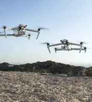


- Copyright
- Trademark Information
- Reading Assistance
- Legend
- Read Before Your First Flight
- Getting Tutorial videos, User Documents, and Relevant Software
- Manual Guide
- Disclaimer
- Important
- Warning
- Warranty Policy
- After-Sales Support
- Maintenance Service
- Company Information
- Table of Contents
- Chapter 1 Product Overview....1
- Chapter 2 Flight Safety 8
- Auto-return 17
- Rebuilding the C2 Link....20
- Flight Restrictions and Unlocking Restricted Zones 21
- Altitude and Distance Limits 25
- Aircraft Calibration....26
- Chapter 6 Autel Enterprise App....100
- Chapter 7 Firmware Updates and Maintenance....151
- Appendix A Product Specifications 157
- Appendix B Declaration of Conformity....170
- Chapter 1 Product Overview
- Introduction
- Tip
- What's In The Rugged Case
- Product Acceptance Checklist
- UAS Introduction
- ■ Aircraft Components And Payload
- ■ Remote Controller Components & The App
- Chapter 2 Flight Safety
- Legal Use Notice
- Chinese Mainland
- The U.S.
- The EU
- Other Countries and Regions
- Flight Operation Guidelines
- Flight Environment Requirements
- Wireless Communication Requirements
- Declaration of Maximum Take-off Mass
- Note
- Obstacle Avoidance System
- Introduction to Visual Sensing System and Millimeter-Wave Radar Sensing System
- Observation Range
- ■ Observation Range of Visual Sensing System
- ■ Observation Range of Millimeter-wave Radar Sensing System
- ■ Observation Range of Radar and Visual Sensing Systems
- Visual Positioning Function
- Visual Obstacle Avoidance Function
- Precautions for Using Obstacle Avoidance Systems
- Auto-return
- Manual Auto-return Activation
- Low Battery Auto-return Activation
- Behavior-based Auto-return Activation
- Auto-return Mechanism
- Auto-return Obstacle Avoidance Process
- Landing Protection Function
- Rebuilding the C2 Link
- Flight Restrictions and Unlocking Restricted Zones
- Geofencing System
- Restricted Zones
- UGZ Import
- Unlocking No-Fly Zones
- Altitude and Distance Limits
- Aircraft Calibration
- Compass Calibration
- 2
- 4
- IMU Calibration
- Gimbal Calibration
- Emergency Stop Propellers During Flight
- Mid-flight Sensing
- Direct Remote Identification
- Standard Flight Operation Process
- Pre-Flight Checklist
- Basic Flight Process
- List of Safeguard
- Chapter 3 Aircraft
- Aircraft Activation
- Aircraft Components
- Preparation Of Aircraft
- Replacing Propellers
- ■ Replacing The Propellers On Rear Arms
- ■ Replacing The Propellers On Front Arms
- Fold/Unfold The Arms
- Arm Light
- RY-Alternate Slow Blinking
- Magnetometer Abnormal/ Calibration Required
- Strobe
- Risk Group 2
- Auxiliary Bottom Light
- Camera
- Camera Structure
- Camera Operations
- ■ Remote Controller Control
- ■ Autel Enterprise App Control
- Gimbal Structure
- Gimbal Mechanical Rotation Range
- Gimbal Operations
- Replacing The Gimbal
- ■ Mounting the Gimbal
- ■ Removing the Gimbal
- Other Functions
- Flight Control System
- Flight Status
- Flight Modes
- Intelligent Flight Function
- ■ Accurate Landing
- ■ Landing Protection
- ■ Intelligent Obstacle Avoidance
- Hot Swap Battery
- Installing the microSD Card
- Connecting to PC/MAC
- Extension Interface
- Protection Rating
- Noise
- ■ A-weighted sound power level
- ■ A-weighted sound pressure level
- Autel SkyLink Image Transmission Function
- ■ Information Of Communication Frequency Bands for Aircraft
- ■ Remote Control Devices
- Chapter 4 Remote Controller
- Introduction
- Remote Controller Components
- Communication Frequency Bands
- Installing the Remote Controller Lanyard
- ■ Steps
- Installing/Storing Command Sticks
- ■ Installing command sticks
- ■ Storing Command sticks
- Turning the Remote Controller On/Off
- ■ Turning the Remote Controller On
- ■ Turning the Remote Controller Off
- Checking the Battery Level of the Remote Controller
- Charging the Remote Controller
- Adjusting the Antenna Position of the Remote Controller
- Remote Controller System Interfaces
- Remote Controller Main Interface
- Shortcut Menu
- Frequency Pairing With the Remote Controller
- Using the Autel Enterprise App
- Using Combination Keys (For Forced Frequency Pairing)
- Selecting Stick Mode
- Stick Modes
- Setting Stick Mode
- Starting/Stopping the Aircraft Motor
- Remote Controller Keys
- Custom Keys C1 and C2
- Take-off/Return-to-Home Button and Pause Button
- Turning On/Off the Remote Controller Prompt Sound
- Calibrating the Remote Controller
- HDMI Screen Output
- Chapter 5 Smart Battery
- Battery Introduction
- Smart Battery Functions
- ■ Battery Level Display
- ■ Self-heating
- ■ Communication
- ■ Power Saving Mode
- ■ Dust and Water Resistance
- ■ Ultra-low Power Mode
- ■ Self-discharge Protection
- ■ Sleep Mode Protection
- ■ Charge Temperature Protection
- ■ Overcurrent Protection
- ■ Overcharge Protection
- ■ Balance Protection
- ■ Short Circuit Protection
- ■ Hot Swapping Batteries
- ■ Over-Discharge Protection
- Smart Battery Usage
- Installing/Removing the Smart Battery
- ■ Install the Smart Battery
- ■ Remove the Smart Battery
- ■ Battery Hot Swap
- Checking Battery Level
- Smart Battery Self-heating
- Charging the Smart Battery
- Storing and Transporting the Smart Battery
- Maintaining and Handling the Smart Battery
- Maintaining the Smart Battery
- Standard Charging and Discharging Process
- Smart Battery Replacement Standards
- Recycling the Smart Battery
- Chapter 6 Autel Enterprise App
- Software Introduction
- Main Interface
- Status Notification Bar
- Shortcut Toolbar
- "Settings" Interface
- Flight Control Parameter Setting
- ■ Set RTH Altitude
- ■ Turn On/Off Altitude Limit
- ■ Turn On/Off Distance Limit
- ■ Set Flight Mode
- ■ Set Home Point
- ■ Calibrate Compass/ IMU
- ■ Set Lost Action
- OA Settings
- ■ Turn On/Off OA System
- ■ Set Warning Distance
- ■ Turn On/Off Radar Display
- ■ Turn On/Off Obstacle Detection Notification Sound
- ■ Turn On/Off Landing Protection
- OA Mode
- RC Settings
- ■ Set Stick Mode
- ■ Calibrate the Remote Controller
- ■ Set RC Custom Button C1/C2
- ■ Set EXP
- ■ Connect to Aircraft
- Image Transmission Settings
- ■ Set Image Transmission Mode
- ■ Set Transmission Frequency Band
- ■ Set Split Screen Effect
- Aircraft Battery
- ■ View Basic Information of the Smart Battery
- ■ Set Battery Warning Threshold
- Gimbal Settings
- ■ Set Gimbal Pitch Sensitivity
- ■ Turn On/Off Extended Pitch Angle
- ■ Gimbal Calibration
- ■ Gimbal Adjustment
- ■ Gimbal Parameters Reset
- RTK Settings
- ■ Enable/Disable RTK Positioning
- ■ Check RTK Connection
- ■ RTK Receive Signal Setting
- ■ Check RTK Coordinates
- More
- ■ Unit Settings
- ■ Light Settings
- ■ Turn On/Off Visual Positioning
- ■ Turn On/Off Submit Flight Data to CAAC
- ■ Enter Registration No.
- ■ Remote ID
- ■ Emergency Stop Propellers During Flight
- ■ View Version Information
- ■ Language Settings
- Attitude Ball
- "Map" Interface
- Camera Interfaces
- Camera Function Area
- ■ View Photo Properties
- ■ Set Video Properties
- ■ Set Infrared Shooting
- ■ Advanced Settings
- "Zoom Camera" Interface
- ■ Adjust the Zoom Factor
- ■ Camera Settings
- "Thermal Camera" Interface
- ■ Set Thermal Color
- ■ Set Radiometric Measurement Mode
- ■ FFC Calibration
- ■ Adjust the Infrared Zoom Factor
- "Wide Angle Camera" Interface
- ■ Adjust the Wide Angle Zoom Factor
- Flight Missions
- Waypoint
- ■ Add Waypoints
- ■ Set Route Name and Route Altitude Type
- ■ Set Flight Altitude
- ■ Set Flight Speed
- ■ Set Yaw Angle
- ■ Set Obstacle Avoidance Mode
- ■ Set Camera Action
- ■ Set Gimbal Pitch Angle
- ■ Add a Waypoint Action
- ■ Set Finish Action
- ■ Set Signal Loss Action
- ■ Set Waypoint Coordinates
- ■ Add Point of Interest
- ■ Set POI Altitude
- ■ Set Associated Waypoints
- ■ Start Pre-flight Check
- ■ Upload a Route and Start a Mission
- Rectangle Mission
- ■ Add a Rectangular Area
- ■ Set Mission Name
- ■ Set Flight Altitude and Relative Height
- - Set Main Course Angle
- - Set Gimbal Pitch Angle
- ■ Turn On/Off Elevation Optimization
- ■ Turn On/Off Double Grid
- ■ Turn On/Off Route Extension
- ■ Turn On/Off Coordinated Turns
- ■ Complete Route Missions
- Polygon
- ■ Add a Polygonal Area
- Pre-flight Check
- Resume Mission
- ■ Resume Mission Options
- Mission and Favorites
- ■ Query
- Edit
- - Favorite
- Delete
- Personal Center
- ■ Query Flight Data
- ■ Purchase "Autel Robotics Care"
- Chapter 7 Firmware Updates and Maintenance
- Aircraft and Remote Controller Firmware Updates
- Aircraft Parts Maintenance
- Troubleshooting Guide
- Appendix A Product Specifications
- A.2 Gimbal Camera
- A.4 Smart Battery
- Appendix B Declaration of Conformity
- Declaration of Conformity
- Appendix C Drone Pilot Information Notices
- As a drone pilot, you are responsible for flying your drone safely.
- Before flying, as a drone pilot, you must
- DO
- DO NOT
Brand : Autel
Model : Alpha
Category : Drone