
MI-10754 - TV Stand Mount-It! - Free user manual and instructions
Find the device manual for free MI-10754 Mount-It! in PDF.


| Product Type | TV Stand |
| Brand | Mount-It! |
| Model | MI-10754 |
| Overall Dimensions (W x D x H) | 48 in x 18 in x 24 in (122 cm x 46 cm x 61 cm) |
| Weight Capacity (Top Shelf) | 110 lbs (50 kg) |
| Total Weight Capacity | 165 lbs (75 kg) |
| Weight of Unit | 45 lbs (20.5 kg) |
| Material | Engineered Wood (MDF) with laminate finish |
| Assembly Required | Yes (tools included) |
| Cable Management | Yes (rear cutouts and grommets) |
| Number of Shelves | 3 (1 fixed, 2 adjustable) |
| Color | Black (may vary by region) |
| TV Size Compatibility | Up to 65 inches |
| VESA Mount Compatible | No (designed as a stand, not a wall mount) |
| Cleaning Instructions | Wipe with a soft, damp cloth. Avoid harsh chemicals. |
| Safety Features | Anti-tip strap included; leveling glides |
| Spare Parts Availability | Contact Mount-It! customer service for replacement parts |
| Warranty | 5-year limited warranty |
| Country of Origin | China |
| Recommended Use | Living room, home theater |
Frequently Asked Questions - MI-10754 Mount-It!
User questions about MI-10754 Mount-It!
0 question about this device. Answer the ones you know or ask your own.
Ask a new question about this device
Download the instructions for your TV Stand in PDF format for free! Find your manual MI-10754 - Mount-It! and take your electronic device back in hand. On this page are published all the documents necessary for the use of your device. MI-10754 by Mount-It!.
USER MANUAL MI-10754 Mount-It!
Installation Instruction
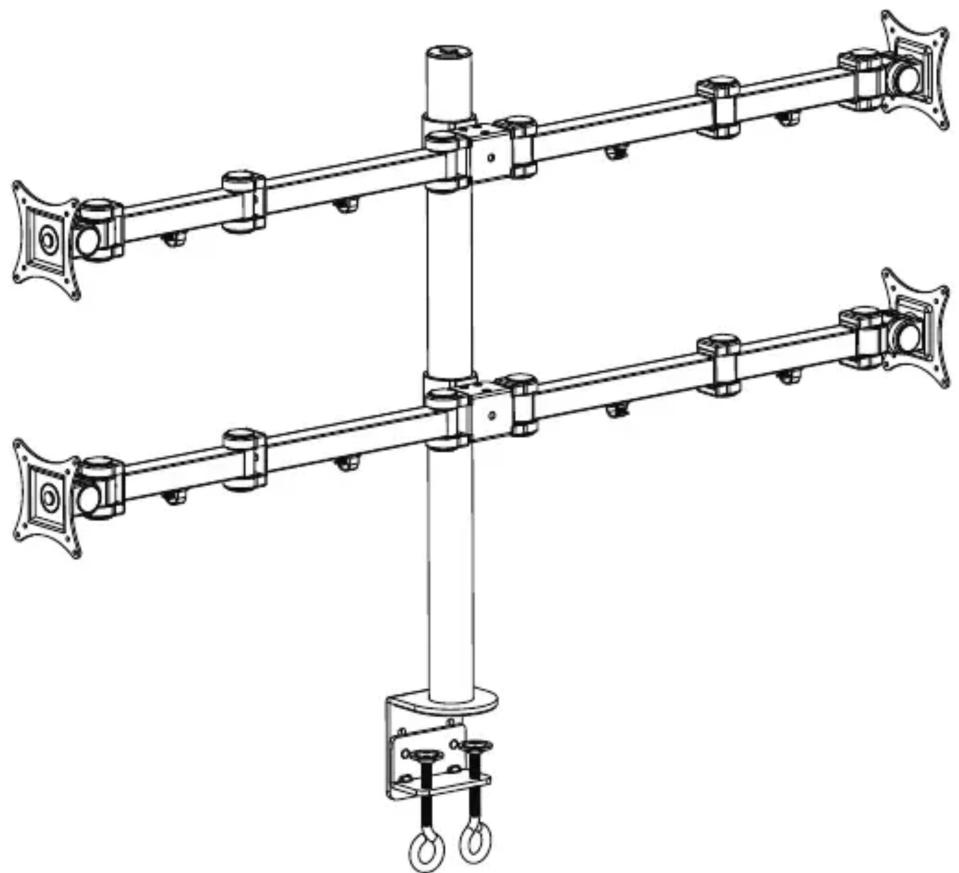
natural_image
Technical line drawing of a mechanical linkage system with two vertical arms and mounting feet (no text or symbols)UNPACKING INSTRUCTIONS
! Carefully open the carton, remove contents and lay out on cardboard or other protective surface to avoid damage.
! Check package contents against the Supplied Parts List in the next page to assure that all components were received undamaged. Do not use damaged or defective parts.
! Carefully read all instructions before attempting installation.
IMPORTANT SAFETY INFORMATION
! Install and operate this device with care. Please read this instruction before installation, and carefully follow all instructions contained herein. Use proper safety equipment during installation.
! Please call a qualified installation contractor for help if you don't understand these directions or have any doubts about the safety of the installation.
Do not use this product for any purpose or in any configuration not explicitly specified in this instruction. We hereby disclaims any and all liability for injury or damage arising from incorrect assembly, incorrect mounting, or incorrect use of this product.
Supplied Par ts List
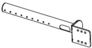
natural_image
Simple line drawing of a mechanical tool or bracket with evenly spaced holes (no text or symbols)(1) 48mm Tube Support-a
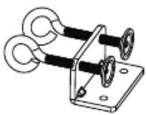
(1) Disconnected "C" Clamp-b
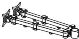
natural_image
Mechanical assembly diagram showing a multi-link rod with cylindrical components and mounting brackets (no text or labels)(2) VESA Plate with Arm Assembled-c
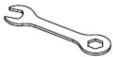
(1) Wrench-I
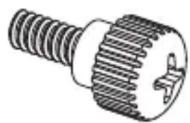
(16)M4x12 Thumb Bolt-d
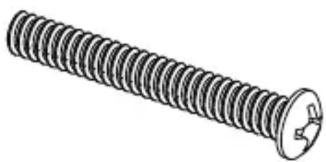
natural_image
Illustration of a standard threaded screw with a circular head and central hole (no text or symbols)(16)M4x30 Bolt-e (32)M4 Washer-f
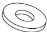
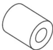
(16)M4 Space-g
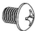
(4)M8x10 Bolt-h (2)M10x15 Bolt-i (1)Allen Key-j
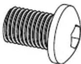
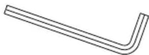
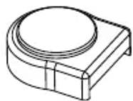
(2) Spare Plastic Cover-k
Tools Required
Phillips Screwdriver

WARNING
CAUTION!
This monitor desktop mount must be securely attached to the horizontal desk. If the mount is not properly installed it may fall, resulting in possible injury and/or damage.
Step 1
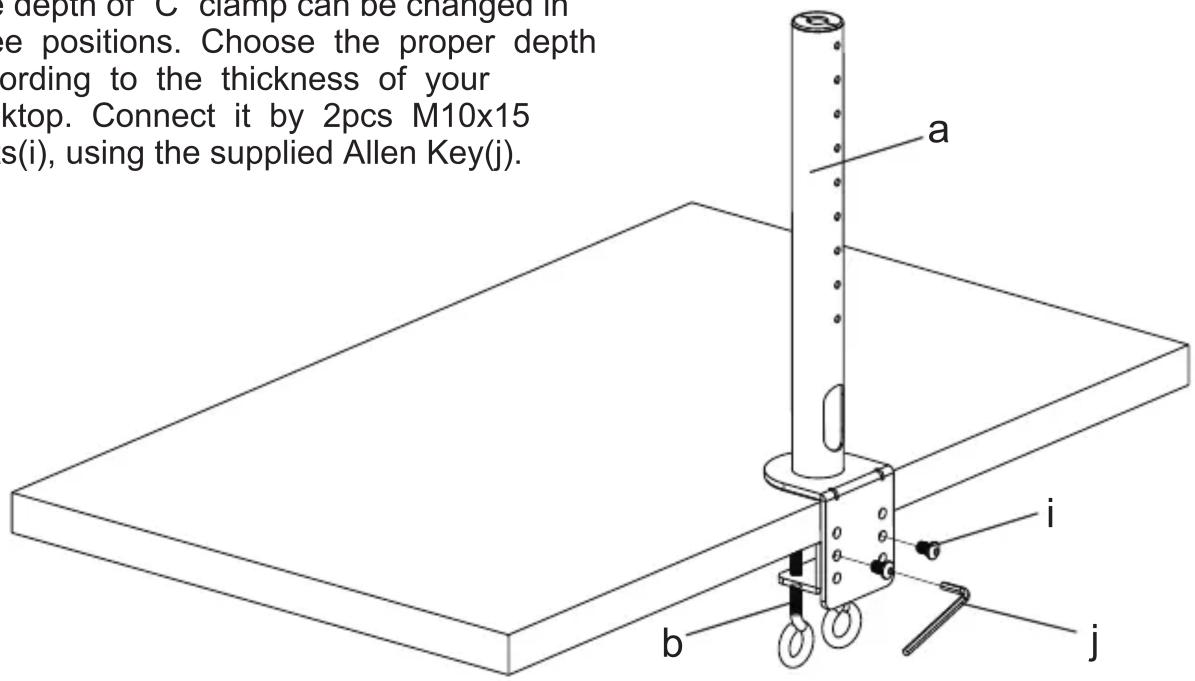
Install the "C" Clamp According to the Desktop Thickness
The depth of “C” clamp can be changed in three positions. Choose the proper depth according to the thickness of your desktop. Connect it by 2pcs M10x15 bolts(i), using the supplied Allen Key(j).
Step 2
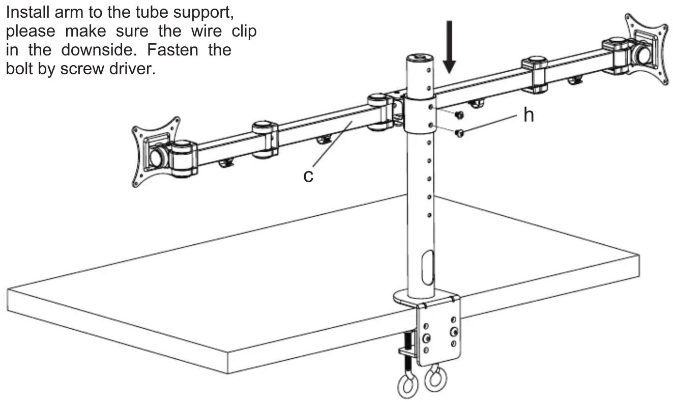
Install Arm to the Tube Support
Install arm to the tube support, please make sure the wire clip in the downside. Fasten the bolt by screw driver.
Step 3
Mount the Monitor to VESA Plate
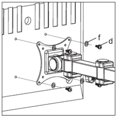
For Flat Back Monitor
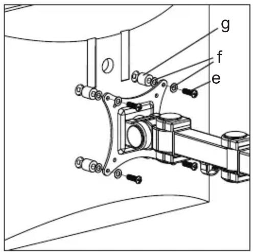
For Curved Back Monitor
Step 4
Do the Necessary Adjustment
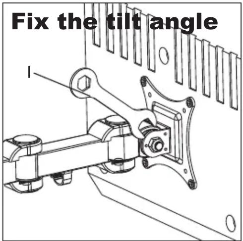
Remove the plastic cover, tighten the nut by the Wrench(I) to fix the tilt angle.
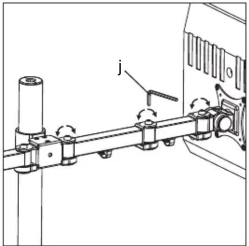
Remove the plastic cover, use the Allen Key(j) to do the necessary adjustment.
Step 5
Manage the Wires
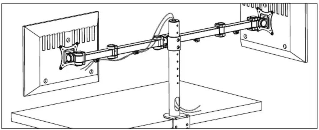
natural_image
Technical line drawing of a mechanical assembly with rotating components and wiring (no text or symbols)- Installation Instruction
- UNPACKING INSTRUCTIONS
- IMPORTANT SAFETY INFORMATION
- Supplied Par ts List
- CAUTION!
- Step 1
- Install the "C" Clamp According to the Desktop Thickness
- Step 2
- Install Arm to the Tube Support
- Step 3
- Mount the Monitor to VESA Plate
- Step 4
- Do the Necessary Adjustment
- Step 5
- Manage the Wires
Brand : Mount-It!
Model : MI-10754
Category : TV Stand