
ProData 2 - Meter Janitza - Free user manual and instructions
Find the device manual for free ProData 2 Janitza in PDF.


| Type of product | Energy and power quality meter |
| Dimensions (W x H x D) | 96 x 96 x 100 mm |
| Weight | 0.5 kg |
| Power supply | 85–265 V AC/DC, 50/60 Hz |
| Display | Backlit LCD, 4 lines x 20 characters |
| Measurement functions | Voltage (L-N, L-L), current, active/reactive/apparent power, power factor, frequency, harmonics up to 63rd order |
| Accuracy (voltage/current) | ±0.2% of reading |
| Accuracy (power/energy) | ±0.5% of reading |
| Communication interfaces | RS485 (Modbus RTU), Ethernet (Modbus TCP), pulse output |
| Data logging | Internal memory up to 4 MB, logging interval configurable from 1 s to 60 min |
| Operating temperature | -10°C to 55°C |
| Mounting | Panel mount (96x96 mm cutout) |
| Safety standards | IEC 61010-1, CAT III 600V |
| Ingress protection | IP54 (front panel) |
| Maintenance and cleaning | Clean with dry cloth; no solvents. Check connection terminals annually. |
| Spare parts and repairability | Contact Janitza service for replacement parts; device not user-serviceable. |
| General information | Designed for energy monitoring in industrial and commercial installations. |
Frequently Asked Questions - ProData 2 Janitza
User questions about ProData 2 Janitza
0 question about this device. Answer the ones you know or ask your own.
Ask a new question about this device
Download the instructions for your Meter in PDF format for free! Find your manual ProData 2 - Janitza and take your electronic device back in hand. On this page are published all the documents necessary for the use of your device. ProData 2 by Janitza.
USER MANUAL ProData 2 Janitza
35633 Lahnau | Germany
Support tel. +49 6441 9642-22
Operating instructions and technical data

Janitza®
ProData 2
Table of contents
General 3
Inspection on receipt 6
Scope of delivery of ProData 2 7
Available accessories 7
Product description 8
Proper use 8
ProData 2 features 9
GridVis network analysis software 10
Connection variants 12
Installation 14
Position of installation 14
Installation 14
Supply voltage 14
RS485 interface 16
Ethernet interface 19
Digital outputs 20
Digital inputs 22
Temperature measurement input 25
Device address (RS485) 26
DIP switch S1 27
Service button S2 27
LED device status 27
Configuration and commissioning 28
Connecting the supply voltage 28
RS485 interface 28
Digital inputs 30
Pulse counters 31
Events 33
Clock 34
Timer 34
Recordings 35
Data memory 35
Rate conversion 36
Temperature measurement input 37
Ethernet 38
Modbus gateway 39
Service and maintenance 41
Service 41
Device calibration 41
Calibration 41
Battery 42
Replacing the battery 43
Firmware update 44
Procedure in the event of faults 45
Technical data 46
Dimension diagrams 50
Connection example 52
General
Copyright
This operating manual is subject to the legal requirements for copyright protection and may not be, either in whole or in part, photocopied, reprinted, or reproduced by mechanical or electronic means, or in any other manner be duplicated or redistributed without the legally binding, written agreement of
Janitza electronics GmbH, Vor dem Polstück 6, D 35633 Lahnau, Germany.
Trademarks
All trademarks and their resulting rights belong to the respective holders of these rights.
Disclaimer
Janitza electronics GmbH takes no responsibility for errors or defects within this operating manual and takes no responsibility for keeping the contents of this operating manual up to date.
Comments on the operating manual
We welcome your comments. In the event that anything in this operating manual seems unclear, please let us know and send us an EMAIL at: info@janitza.de
Meaning of the symbols
The following pictograms are used in this manual:

Dangerous voltage!
Danger to life or risk of serious injury. Disconnect the system and device from the power supply before beginning work.

Caution!
Please follow the documentation. This symbol warns of possible dangers that can arise during installation, commissioning and use.

Note!
ProData 2
Instructions for use
Please read the operating manual included in the delivery as well as all other publications that must be referred to for working with this product (in particular for the installation, operation or maintenance).
Follow all safety regulations and warning information. If you do not follow the information, it can result in bodily injury and/or damage to the product.
Any unauthorised changes or use of this device, which go beyond the mechanical, electrical or otherwise stated operating limitations, can result in bodily injury or/and damage to the product.
Any such unauthorised changes constitute "misuse" and/or "negligence" in terms of the warranty for the product and, therefore, invalidate the warranty for covering any potential damage that result.
This device is to be operated and maintained exclusively by specialised personnel.
Specialised personnel are persons who, based on their respective training and experience, are qualified to recognise risks and prevent potential dangers that can be caused by the operation or maintenance of the device.
Additional legal and safety regulations required for the respective application are to be followed when using the device.

If the device is not operated according to the operating manual, protection is no longer ensured and hazards can be presented by the device.

Conductors made from single wires must be fitted with wire-end ferrules.

Only pluggable screw terminals with the same number of poles and the same type of construction are permitted to be connected together.
Concerning these operating instructions
These operating instructions are part of the product.
- Read the operating instructions before using the device.
- Keep the operating instructions throughout the entire service life of the product and have them readily available for reference.
- Pass the operating instructions on to each subsequent owner or user of the product.
Inspection on receipt
The prerequisites of faultless, safe operation of this device are proper transport and proper storage, setup and assembly, as well as careful operation and maintenance. If it can be assumed that risk-free operation is no longer possible, the unit must be immediately put out of operation and secured against being put back into operation again.
Packing and unpacking must be carried out with customary care without the use of force and only using suitable tools. The devices should be visually checked for flawless mechanical condition.
It can be assumed that risk-free operation is no longer possible if the device, for example,
- has visible damage,
- no longer works despite being connected to the mains power supply,
- has been exposed to prolonged adverse conditions (e.g. storage outside the permissible climate limits without being adapted to the room climate, condensation, etc.) or rough handling during transportation (e.g. falling from a height, even if there is no visible external damage, etc.)
- Please check the delivered items for completeness before you start installing the device.
Scope of delivery of ProData 2
Number Part no. Description
| 1 52.24.xxx | ^1) ProData 2 |
| 1 33.03.198 | Operating instructions |
| 1 33 03 342 | Safety instructions |
| 3 52 24 25x | ^1) Accessories pack ProData 2 |
^1) For the item number, see the delivery note
Available accessories
Part no. Description
| 21.01.058 Battery 3 V, TYPE CR2032 (approved in acc. with UL1642) |
| 52.24.111 S0 module for a group of S0 inputs, equipped with 1.3 kOhm resistors |
ProData 2
Product description
Proper use
The ProData 2 is designed for fixed installation (mounting rail assembly) in low voltage switchgear indoors and is suitable for recording and saving counter values and process data.
The data can be used to evaluate the energy consumption and operating hours, or to monitor switching states and faults in buildings, production facilities, etc.
The auxiliary voltage, the digital inputs, the interfaces, etc. are connected via intrinsically safe plug-in terminals and via an Ethernet plug.
ProData 2 features
• 15 digital/pulse inputs
- 3 digital outputs, switchable via Modbus, weekly timer, boundary value and temperature monitoring
• Temperature measurement input
- Ethernet interface (Modbus TCP)
• RS485 (Modbus RTU, slave, up to 115 kbps)
• 32 MB flash memory (29 MB usable for recordings)
• Assembly on mounting rails (35 mm)
- Connection via pluggable screw terminals
- Clock and battery function
- Weekly timer
• Threshold value monitoring
- Modbus gateway functionality ^1
- Working temperature range -40 °C .. +55 °C
- Saving minimum and maximum values (with time stamp)
- Configurable records, can be read out via RS485 and Ethernet
ProData 2
Parameterisation
The parameterisation of all device functions takes place via the RS485 serial interface or via Ethernet and with the GridVis programming software.
The Modbus protocol can be used to change and retrieve data using the Modbus address list (available on the Internet or the enclosed CD).
GridVis network analysis software
The ProData 2 can be programmed and read out using the GridVis network analysis software. For this, a PC must be connected to the ProData 2 via a serial interface (RS485) or via Ethernet (see the connection variants).
GridVis features
- Programming the ProData 2
• Graphical representation of measured values

Additional components that are not included in the scope of deliverables will be required for parametrisation via the RS485 interface.
ProData 2
ProData 2
Connection variants
Connection of a ProData 2 to a PC via an interface converter:
Direct connection of a ProData 2 to a PC via Ethernet.

flowchart
graph LR
    A["PC GridVis"] -->|RS232| B["RS232 / RS485"]
    B -->|RS485| C["ProData 2"]
    B -->|RS485| D["UMG 96RM"]

flowchart
graph LR
    A["PC GridVis"] -->|Ethernet (twisted patch cable)| B["ProData 2"]
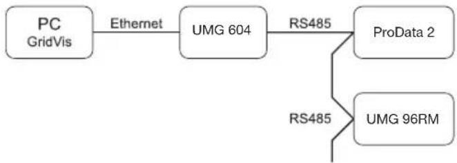
Connection of a ProData 2 via a UMG 604 as a gateway.
Connection of a ProData 2 to a PC via Ethernet.
flowchart
graph LR
    A["PC GridVis"] -->|Ethernet| B["UMG 604"]
    B -->|RS485| C["ProData 2"]
    B -->|RS485| D["UMG 96RM"]

flowchart
graph TD
    A["PC GridVis"] -->|Ethernet| B["Switch"]
    B -->|Ethernet| C["ProData 2"]
Connection of a ProData 2 with gateway function to a PC via Ethernet.
Connecting a ProData 2 as a Modbus slave device.

flowchart
graph LR
    A["PC GridVis"] -->|Ethernet| B["ProData 2 (Gateway)"]
    B -->|RS485| C["UMG 103 (Modbus slave)"]
    B -->|RS485| D["UMG 104 (Modbus slave)"]

flowchart
graph TD
    A["PC GridVis"] --> B["Ethernet"]
    B --> C["ProData 2 (Modbus slave)"]
    C --> D["RS485"]
    D --> E["UMG 103 (Modbus slave)"]
    C --> F["RS485"]
    F --> G["UMG 104 (Modbus slave)"]
    F --> H["RS485"]
    H --> I["UMG 604 (Modbus master)"]
    B --> J["Ethernet"]
In this installation, the ProData 2 can forward queries (e.g. from the GridVis software) to a Modbus slave device. However, it CANNOT query Modbus slave devices independently!
The ProData 2 is configured as a Modbus slave. Communication to the ProData 2 can take place directly via Ethernet or via the Modbus master.
The ProData 2 cannot forward any Ethernet queries to a Modbus slave device!
RS485 mode: Gateway; address 3=1
RS485 mode: Slave; address 3=0
ProData 2
Installation
Position of installation
The ProData 2 is designed for fi xed installation in low voltage switching devices indoors. It is assembled on a 35 mm mounting rail in accordance with DIN EN 60715. Can be installed in any mounting position.

Installation
Supply voltage
The ProData 2 requires a supply voltage to operate. The supply voltage is connected to the front side of the device via a 2-pin plug-in terminal.
Before connecting the supply voltage, make sure that the voltage and frequency correspond to the details on the ratings plate.
The supply voltage must be connected through a UL/IEC approved fuse or a circuit breaker.

- If installed in a building, a disconnector or circuit breaker must be provided for the supply voltage.
- The disconnector must be installed near the device and easily accessible to the user.
- The switch must be marked as the circuit breaker for this device.
- Voltages which are over the permitted voltage range can destroy the device.

Fig. Connection example of the supply voltage to a ProData 2 via an external mains supply.

Fig. Connection example of the supply voltage to a ProData 2.
ProData 2
RS485 interface
In the ProData 2, the RS485 interface is designed as a 2-pin plug contact, which communicates via the Modbus RTU protocol (also see Parameter programming).

Fig.: Placement in the middle of the segment; termination via DIP switch S1 deactivated (OFF)

Fig.: Placement at the end of the segment; termination via DIP switch S1 activated (ON)
Termination resistors
The cable is terminated with resistors (120 Ohm, 1/4 W) at the beginning and at the end of a segment.
Termination within the device is possible via the S1 DIP switch of the ProData 2.

flowchart
graph TD
    A["Correct"] --> B["Component 1"]
    A --> C["Component 2"]
    A --> D["Component 3"]
    A --> E["Component 4"]
    A --> F["Component 5"]
    G["Incorrect"] --> H["Component 1"]
    G --> I["Component 2"]
    G --> J["Component 3"]
    G --> K["Component 4"]
    G --> L["Component 5"]
Terminal strip in the cabinet.
Device with RS485 interface (without terminating resistor).
☐ Device with RS485 interface (with terminating resistor on the device).
Screening
Twisted screened cable should be used for connections via the RS485 interface.
- Earth the screens of all cables that lead to the cabinet upon entering the cabinet.
- Connect the screens over a generous area and in a manner that will conduct well to a low-noise earth.
- Gather the cables mechanically above the earthing clamp in order to avoid damage due to cable movements.
- Use suitable cable glands to feed the cables into the cabinet - e.g. armoured conduit couplings.
Cable type
The cable used must be suitable for an environmental temperature of at least 80 °C.
Recommended cable types:
Unitronic Li2YCY(TP) 2x2x0.22 (from Lapp Kabel)
Unitronic BUS L2/FIP 1x2x0.64 (from Lapp Kabel)
Maximum cable length
1200 m at a baud rate of 38.4 kbits.

Fig. Screening procedure at cabinet entry.
Bus structure
- All devices are connected in a bus structure (line) and each device has its own address within the bus (see also Parameter programming).
- Up to 32 subscribers can be connected together in a single segment.
- The cable is terminated with resistors (bus termination 120Ohm, 1/4W) at the beginning and at the end of a segment.
- With more that 32 subscribers, repeaters (amplifiers) must be used to connect the individual segments.
-
Devices for which the bus connection is switched on must be under current.
-
It is recommended that the master be placed at the end of a segment.
- If the master is replaced with a bus connection, the bus must be switched off.
- Replacing a slave with a bus connection that is either switched on or de-energised can destabilise the bus.
- Devices that are not connected to the bus can be replaced without destabilising the bus.

flowchart
graph TD
    A["Master"] --> B["Slave Slave"]
    A --> C["Slave Repeater"]
    A --> D["Master"]
    B --> E["Slave Slave Slave"]
    C --> F["Slave Slave"]
    D --> G["Master"]
    style A fill:#999,stroke:#333
    style B fill:#ccc,stroke:#333
    style C fill:#ccc,stroke:#333
    style D fill:#ccc,stroke:#333
    style E fill:#ccc,stroke:#333
    style F fill:#ccc,stroke:#333
    style G fill:#ccc,stroke:#333
Ethernet interface
The Ethernet network settings should be specified by the network administrator and set accordingly on the ProData 2 using the GridVis software. If the network settings are not known, the ProData 2 may not be integrated into the network via the patch cable.

LEDs of the Ethernet interface
| LED Function |
| Yellow Illuminates when a connection (LINK) is present. |
| Green Illuminates sporadically when a network activity occurs. |

Caution!
Connection of the ProData 2 to the Ethernet may only be carried out after discussion with the network administrator.

Caution!
The ProData 2 is factory-set to the fixed IP address 10.10.10.200 (subnet mask 255.0.0.0). The allocation of a dynamic IP address is disabled. The settings can be changed via a suitable Ethernet connection using the GridVis software.
ProData 2
Digital outputs
The ProData 2 features three digital outputs that have a joint reference. The status of each of the outputs is shown by the corresponding LED. The corresponding LED illuminates red when the output is set to active, regardless of whether there is a continuing connection to this interface.
Digital output 1 can also be configured to monitor the temperature. This can be switched via the temperature measurement input and using a comparator.
- The digital outputs can be controlled via Modbus and the weekly timer.
- An external auxiliary voltage is required.
- The digital outputs can switch AC and DC loads.
- The digital outputs are not short-circuit proof.
- Connected cables that are longer than 30 m must be shielded when laid.
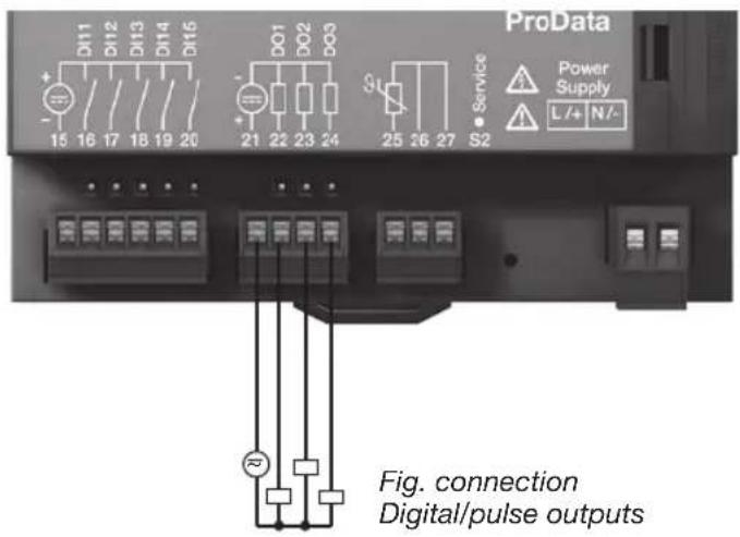
DC connection example

flowchart
graph TD
    A["ProData 2 Digital outputs 1-3 Digital outputs 1-3"] --> B["Digital Output 1"]
    A --> C["Digital Output 2"]
    A --> D["Digital Output 3"]
    B --> E["External Auxiliary voltage"]
    C --> E
    D --> E
    E --> F["24 V AC/DC"]
    F --> G["+"]
    F --> H["-"]
    I["DC"] --> J["K1"]
    K["DC"] --> L["K2"]
    M["21"] --> N["Digital Output 1"]
    O["22"] --> P["Digital Output 2"]
    Q["23"] --> R["Digital Output 3"]
    S["24"] --> T["Digital Output 3"]
Fig. Example of two relays connected to the digital outputs

Caution!
Digital outputs are not short-circuit proof.

Functions for the digital outputs can be adjusted clearly in the GridVis software. A connection between the ProData 2 and the PC via an interface is required to use the GridVis software.

When using the digital outputs as pulse outputs, the auxiliary voltage (DC) must have a maximum residual ripple of 5%.
ProData 2
Digital inputs
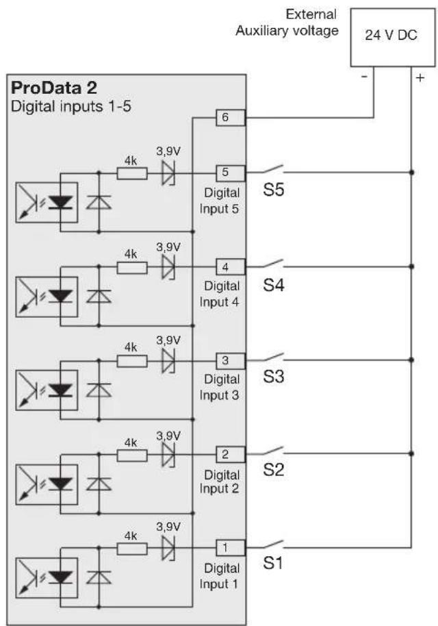
The ProData 2 features 15 digital inputs, which are subdivided into three groups of 5 inputs, each with a joint earth.
The status of each of the inputs is shown by the corresponding LED. The corresponding LED illuminates green if there is a signal on this interface.
An input signal is recognised (signal "1") if a voltage of at least 18 V is applied (typically 4 mA at 24 V). If the voltage is lower than 5 V DC, no input signal exists (signal "0").
Wiring longer than 30 m must be screened.
Correct polarity of the supply voltage (20 ... 30 V DC) must be ensured!

Caution!
Correct polarity of the supply voltage for the digital inputs must be ensured.

flowchart
graph TD
    A["ProData 2 Digital inputs 1-5"] --> B["6"]
    A --> C["5"]
    A --> D["4"]
    A --> E["3"]
    A --> F["2"]
    A --> G["1"]
    B --> H["S5"]
    C --> I["S4"]
    D --> J["S3"]
    E --> K["S2"]
    F --> L["S1"]
    G --> M["External Auxiliary voltage"]
    M --> N["24 V DC"]
    style A fill:#f9f,stroke:#333
    style B fill:#ccf,stroke:#333
    style C fill:#ccf,stroke:#333
    style D fill:#ccf,stroke:#333
    style E fill:#ccf,stroke:#333
    style F fill:#ccf,stroke:#333
    style G fill:#ccf,stroke:#333
    style H fill:#dfd,stroke:#333
    style I fill:#dfd,stroke:#333
    style J fill:#dfd,stroke:#333
    style K fill:#dfd,stroke:#333
    style L fill:#dfd,stroke:#333
Fig. Example of the connection of external switch contacts S1 to S5 to digital inputs 1 to 5.
ProData 2
S0 pulse input
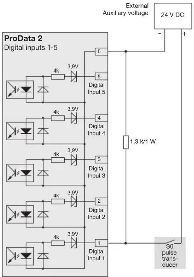
You can connect an S0 pulse transducer per DIN EN62053-31 to any digital input.
This requires an auxiliary voltage with an output voltage in the range 20 .. 27 V DC and a resistor of 1.3 kOhm/1 W.
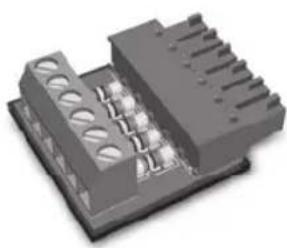
S0 plug-in module
(optional, article number 52.24.111)
- Enables simple and fast connection of S0 pulse transducers.
- Module for a group of 5 inputs with integrated resistors.
natural_image
3D rendering of a black electronic component with slots and mounting holes (no text or symbols visible)Fig.: S0 plug-in module to connect S0 pulse transducers
flowchart
graph TD
    A["ProData 2 Digital inputs 1-5"] --> B["6 Digital Input 5"]
    A --> C["5 Digital Input 4"]
    A --> D["4 Digital Input 3"]
    A --> E["3 Digital Input 2"]
    A --> F["2 Digital Input 1"]
    B --> G["External Auxiliary voltage"]
    C --> G
    D --> G
    E --> G
    F --> G
    G --> H["24 V DC"]
    H --> I["S0 pulse transducer"]
    I --> J["1.3 k/1 W"]
    J --> G
Temperature measurement input
Temperature sensors with a resistance region of between 60 Ohm and 2.6 kOhm can be connected to the temperature measurement input. Do not exceed the total resistance load (sensor + cable) of 4 kOhm.
The temperature measurement value is determined once per second. The sensor type and the desired temperature offset can be set using the GridVis software or a Modbus.

Example:
3-line connection PT100
Example:
2-line connection PT1000
Example:
2-line connection KTY83

When connecting the KTY83/84 sensor, correct polarity must be ensured. The negative connection (indicated with a black ring) must be connected to terminal 25.
Device address (RS485)
If multiple devices are connected to each other via the RS485 interface, a master device can only identify the devices by their device address. Within a network, each device must have its own device address.
The device address can be confi gured via the rotary switch that is available on the ProData 2. In this way addresses can be set in the range of 1 to 99.
X10 X1
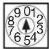
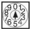
The device address 0 0 is reserved and may not be assigned for operation with Modbus communication.

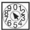
The device address 99 is reached by setting the rotary switch X10 to 9 and X1 to 9. A device address with a higher value cannot be set for the ProData 2.

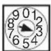
Example: Setting the device address to 13.

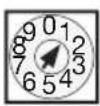
Factory setting: Device address 1.

DIP switch S1
If the ProData 2 is integrated into a bus via the RS485 interface, a termination resistor has to be set (see the RS485 interface, termination resistors chapter) depending on the placement of the ProData within the segment.
Termination within the device is possible via the S1 DIP switch of the ProData 2.
Service button S2
The service button is only to be used by instructed service employees and must not be pressed by those who are not acquainted with it.
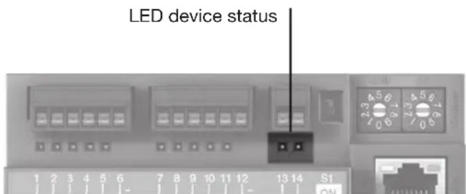
| LED Function | |
| Red/Green Shows the initialisation process during the start phase (approx. 15 seconds) | |
| Green Device is operational | |
| Red Device error | |
| Red (flashes) | Set date/time |
| Red/Green If the start process is complete and both LEDs are still illuminated, the initialisation process was interrupted. Perform a device update (firmware) via the software. | |
LED device status
The status LEDs below the RS485 interface show different states of the device. During the start process, the red and the green LEDs illuminate at the same time. Once the start process is complete (approximately 15 seconds), the red LED illuminates; the green LED indicates flawless operation of the device.
ProData 2
Configuration and commissioning
Connecting the supply voltage
The supply voltage must be connected to configure and commission the ProData 2.
The supply voltage level for the ProData 2 is specified on the rating plate.
RS485 interface
The following parameters must be set to operate the RS485 interface:
- Device termination (termination resistor)
- Device address (see the device address chapter)
- Baud rate
- Stop bits
The factory settings and the setting area for the baud rate are specified in the parameter list.
Device termination (termination resistor)
For fault-free operation of the devices within a bus structure, termination resistors must be set at the start and the end of a segment. If the ProData 2 is at the start or the end of a segment, a termination can be switched via the DIP switch S1.

ON: Device termination active (120 Ohm) OFF: Device termination inactive

Baud rate
A common baud rate can be adjusted for the RS485 interface. The baud rate must be selected consistently in the grid and set via address 002.
Address 004 can be used to set the number of stop bits where 0=1 bit (factory setting) and 1=2 bits. Data bits (8) and parity (none) are fixed default values.
| Setting Baud rate |
| 0 9.6kbps |
| 1 19.2kbps |
| 2 38.4kbps |
| 3 57.6kbps |
| 4 115.2kbps (factory setting) |
ProData 2
Digital inputs
The ProData 2 features 15 digital inputs, which are subdivided into three groups of 5 inputs:
- The status of each of the inputs is shown by the corresponding LED. The corresponding LED illuminates green if there is a signal on this interface.
- The GridVis software can be used to assign a name, unit and description to each digital input.
- The states of the digital inputs are each located on their own Modbus address.
- The last 16 switches (events) are logged with a time stamp for each digital input.
- Digital inputs 1-10 can be configured as functional inputs. Operating these inputs as pulse counters is not possible in this configuration.
- A tariff selection can be assigned to each digital input where only the highest activated tariff runs.
Functional attributes
Specific functions can be assigned to digital inputs 1 - 10. In this function mode, operating these inputs as pulse counters is not possible.
Digital input 1 to 8:
Configuration as tariff converter
Digital input 9:
Synchronisation of the internal clock; choosing between minute or hour synchronisation is possible. However, synchronisation is also possible via a Modbus address.
Digital input 10:
Reset for the synchronisation values (see notes). You also have the option of resetting the mean values via a Modbus address.
Pulse counters
All digital inputs can be operated with a frequency of 25 Hz. Here, the pulse duration and the pulse interval must be greater than 20 ms. The typical pulse duration for S0 pulses is 30 ms.

The maximum number of pulses per hour is based on the minimum pulse duration and the minimum pulse interval:
| Pulse length | Pulse interval Max. pulse/h |
| 20 ms 20 ms | 90 000 pulse/h |
| 30 ms 30 ms | 60 000 pulse/h |
| 50 ms 50 ms | 36 000 pulse/h |
| 100 ms 100 ms | 18 000 pulse/h |
| 500 ms 500 ms | 3600 pulse/h |
| 1 s 1 s 1800 pulse/h | |
| 10 s 10 s 180 pulse/h | |
Examples of the maximum possible number of pulses per hour.
The pulse counters can be configured with a simultaneous measurement value or power calculation. The pulses are counted as 64-bit numbers and overflow after approximately 1.17 × 10^10 years of continuous operation (25 Hz).
Pulse value:
A pulse value can be assigned to each digital input. Use the impulse value to specify the measurement value or power value (e.g. energy) to which a pulse should correspond.
Measurement value calculation:
$$ \text { Measurement value } = \text { pulse } \times \text { pulse value } $$
Power value calculation:
$$ \text { Power value } = \frac {\text { pulse x pulse value }}{\text { Time [sec] }} $$
ProData 2
S0 power values
Since the pulse interval may be very large, continual calculation of the measurement or power values is not possible. For this reason, only the mean values are calculated. For measurement value calculation, the mean values are calculated from the number of pulses per period multiplied by the pulse value. For power value calculation, this value must be divided by the amount of time that can be set.
The period is assigned to the digital input and can be set in a region of 1 to 60 minutes. After the period ends, the value can be called via the Modbus.
For each digital input, an external synchronisation can be triggered; in this case, a synchronisation pulse completes one period and starts a new period. A fixed capture period of 30 seconds is preset for external synchronisation. If no synchronisation pulse exists after the period expires, a maximum of 30 seconds is waited and the software then carries out the synchronisation. All further periods are synchronised by the software.
A period of 15 min is the factory setting.

The calculation result for the S0-power value is not until the end of the cycle available.
Events
Events are status changes of the relevant digital inputs that are logged in a ring buffer.
Status changes (events):

Event: 15 14 13 12 11 10 9 8 7 6 5 4 3 2 1 0
The ring buffer saves the last 16 events for each digital input and specifies the time stamp and the current status. Within the ring buffer, the event field with the index 0 always describes the current status of the relevant digital input.

donut
| Value | Color | |---|---| | 0 | Dark Gray | | 1 | Light Gray | | 2 | Light Gray | | 3 | Medium Gray | | 4 | Medium Gray | | 5 | Medium Gray | | 6 | Medium Gray | | 7 | Medium Gray | | 8 | Medium Gray | | 9 | Medium Gray | | 10 | Medium Gray | | 11 | Medium Gray | | 12 | Medium Gray | | 13 | Medium Gray | | 14 | Medium Gray | | 15 | Medium Gray | | Current value | Dark Gray | | Oldest value | Light Gray |Fig.: Ring buffer for 16 field elements
ProData 2
Clock
The internal device clock is recorded in UTC (Universal Time Coordinated) format with a resolution of 1 second and converted into the local time via a possible configuration of the time zone and the switch between daylight saving time and standard time.
The time can be read and set via a Modbus address. The GridVis software can be used as a user-friendly way to set the clock.
A minute or hour synchronisation of the time takes place via digital input 9.
Example:
| Current device time Time after minute pulse | |
| 15:05:51 15:06:00 | |
| 15:05:11 15:05:00 | |
| Current device time Time after hour pulse | |
| 15:05:11 15:00:00 | |
When synchronising the time via Ethernet (NTP), the external clock is only set and is read during a restart. The NTP service can receive broadcasts (passive) or send queries to an NTP server (active). In active mode, an NTP server with the IP address must be set. A name resolution is not possible.
Timer
In the ProData 2, 64 independent weekly timers can be set; here, the resolution is 1 minute. The weekly timer defines an active period within a day; the active day must be released within a week.
Example of an active period:
From 9:25 to 11:45 am Sunday, Monday and Friday
The weekly timers can be configured as tariff converters (1..8), setting digital outputs 1-3, but also as "inoperable". The status can always be queried via the Modbus. The states of the timer are linked via an OR operator to the digital output.
The weekly timer must be set using the GridVis software.
Recordings
Recordings in the data flash (for GridVis software):
- Up to 8 recordings with up to 29 values can be stored in the ProData 2.
- The smallest time basis for recordings is 1 minute and the largest time basis is 60 min.
- Recordings and the names of the power values can be adjusted and extended via the GridVis software.
Data memory
The size of the ProData 2's flash memory is 32 MB; 24 MB is available for recordings and 5 MB is available for the cyclical drawings of the work values.
Recording all 15 channels at a recording interval of 15 minutes results in a recording depth of approximately 1024 days.
The memory is read or deleted via a Modbus or via the GridVis software.
ProData 2
Rate conversion
A tariff selection of 1 to 8 can be assigned to each digital input; the tariffs can be activated via digital inputs 1-8, via a Modbus and via the timer. Each input can be reset individually via the GridVis software.
The tariff conversion via Modbus takes place via addresses 1940 (for digital input 1) to 1954 (digital input 16). The relevant tariff is to be selected by setting or deleting bits 0 to 7. Only the highest-value tariff is evaluated.
Bit: 01234567

Example of tariff 2 set: If the value is set to address 1940, the tariff conversion for digital input 1 applies.
Bit-by-bit representation of the tariff conversion
| Tariff T1 | T2 | T3 | T4 | T5 | T6 | T7 | T8 | ||||
| Bit 0 1 | 2 | 3 | 4 | 5 | 6 | 7 | |||||
| Input Address | |||||||||||
| 1 1940 | 0 | 1 | 0 | 0 | 0 | 0 | |||||
| 2 1941 | 0 | 0 | 0 | 0 | 0 | 0 | |||||
| ... ... | |||||||||||
| 15 | 1954 | 0 | 0 | 1 | 0 | 0 | 0 | 0 | |||
Example: For digital input 1, tariff 2 is set, for input 15, tariff 3 is set.
In addition to the tariff conversion, the individual tariffs are to be activated via Modbus addresses 1700 (tariff 1) to 1707 (tariff 8).
| Address | Tariff | |
| 1700 | 1 | 0 = tariff deactivated, 1 = tariff activated |
| 1701 | 2 | 0 = tariff deactivated, 1 = tariff activated |
| 1702 | 3 | 0 = tariff deactivated, 1 = tariff activated |
| ... | ... ... | |
| 1707 | 8 | 0 = tariff deactivated, 1 = tariff activated |
Temperature measurement input
The temperature measurement value is determined once per second. The sensor type and the desired temperature offset can be set using the GridVis software or a Modbus.
Threshold value monitoring of the temperature measurement input is possible using a comparator. The results of the comparator can be combined with the OR operator.
The combination result of the comparator group can be assigned to digital output 1.
Sensor types:
- PT100 / PT1000
- KTY83 / KTY84

Threshold value monitoring can be adjusted clearly in the GridVis software. A connection between the ProData 2 and the PC via an interface is required to use the GridVis software.
Fig.: GridVis software, configuration menu
![GridVis-4.0.2[2011-05-28 14-34-12] [grid1] File Edit View Tools Window Help Configuration[Genit-6] Transmit Transmit to... Reload Factory default Save to file Load from file Identity Averaging intervals Recording configuration time Timezone I/O configuration Temperature monitoring Clock time Serial ports ip configuration I/O naming Measuring input External temperature 1 Temperature sensor PT100 Temperature offset 3,0 celsius Threshold temperature $0,0 celsius Hysteresis 5 celsius Minimum exceeding time 0 seconds Minimum run time 0 seconds Jun 17, 2013 1:17:31 PM CEST (GMT +G2+00)](/content/2026/05/852813/images/46d8a2e00835c09ff462ba820950c4220aab921052fa9ad9e6b3ba925ac800eb.jpg)
Ethernet
Within an Ethernet, each device has a unique TCP/IP address that can be assigned manually or from a DHCP server.
Fixed IP address:
In simple networks without a DHCP server, the network address of the ProData 2 must be set via a Modbus or via the GridVis software.
BootP:
BootP allows for fully-automatic integration of the ProData 2 into an existing network. However, BootP is an older protocol and does not provide the scope of functions provided by DHCP.
DHCP mode:
DHCP allows for fully-automatic integration of a ProData 2 into an existing network with a DHCP server without additional configuration. When started, the ProData 2 automatically obtains the IP address, the network mask and the gateway from the DHCP server.
Factory default settings: Fixed IP address
IP address 10.10.10.200
Subnet mask 255.0.0.0
DHCP
deactivated

Caution!
Connection of the ProData 2 to the Ethernet may only be carried out after discussion with the network administrator.

Caution!
The device is factory-set to the fixed IP address 10.10.10.200 (subnet mask 255.0.0.0). The allocation of a dynamic IP address is disabled.
The settings can be changed via a suitable Ethernet connection using the GridVis software.
Modbus gateway
The ProData 2 can be set as a Modbus gateway with the following limitations:
- In this mode, the ProData 2 cannot be used as a Modbus RTU slave device.
- In this mode, the ProData 2 converts Modbus TCP packages from port 502 (only TCP) to Modbus RTU and sends these via the RS485 interface. If a response is received via the RS485 interface within a timeout period that can be set, this is converted to Modbus TCP again and sent via the IP connection.
- The ProData 2 can only forward queries (e.g. from the GridVis software) to a Modbus slave device. It CANNOT query Modbus slave devices independently.

flowchart
graph TD
    A["PC with GridVis software"] --> B["Ethernet"]
    A --> C["Ethernet"]
    B --> D["ProData 2 as gateway"]
    C --> E["UMG 104 Slave 1"]
    C --> F["UMG 103 Slave 2"]
    C --> G["UMG 604 Slave 3"]
    D --> H["Modbus Modbus Modbus"]
    E --> H
    F --> H
    G --> H
Fig.: Connection variant with ProData 2 as a gateway. The ProData 2 converts the queries of the GridVis software (TCP packages via Ethernet) for the Modbus slave devices (Modbus RTU) and forwards these via the RS485 interface (RS485 mode: Gateway; Addr. 3=1).
ProData 2

flowchart
graph TD
    A["PC with GridVis software"] --> B["Ethernet"]
    B --> C["Modbus"]
    B --> D["Modbus Modbus"]
    C --> E["ProData 2 as slave 1"]
    D --> F["UMG 104 Slave 2"]
    D --> G["UMG 103 Slave 3"]
    D --> H["UMG 604 Master"]
Fig.: Connection variant with ProData 2 as a Modbus RTU slave device.
The ProData 2 can be addressed directly via Ethernet but it cannot send any Ethernet queries to a Modbus slave device. The ProData 2 contains a slave function in the RS485 bus and can be read from the master device (UMG 604). (RS485 mode: Slave; Addr. 3=0).
Service and maintenance
The device underwent various safety checks before delivery and is marked with a seal. If a device is open, then the safety checks must be repeated. Warranty claims will only be accepted if the device is unopened.
Repairs
Repair work can be carried out by the manufacturer only.
Front film
The front film can be cleaned with a soft cloth and standard household cleaning agent. Do not use acids and products containing acid for cleaning.
Disposal
The ProData 2 can be reused or recycled as electronic scrap in accordance with the legal provisions. The permanently installed lithium battery must be disposed of separately.
Service
Should questions arise, which are not described in this manual, please contact the manufacturer directly.
We will need the following information from you to answer any questions:
- Device name (see rating plate),
- Serial number (see rating plate),
- Software release,
- Supply voltage,
- Precise description of the error.
Device calibration
The devices are calibrated by the manufacturer at the factory - it is not necessary to recalibrate the device providing that the environmental conditions are complied with.
Calibration
We recommend having a re-calibration carried out by the manufacturer or an accredited laboratory approximately every 5 years.
ProData 2
Battery
The internal clock is fed from the supply voltage. If the supply voltage fails then the clock is powered by the battery.
The clock provides date and time information, e.g. for the records and events.
The life expectancy of the battery is at least 5 years with a storage temperature of +45 °C. The typical life expectancy of the battery is 8 to 10 years.
The battery status (full capacity, undervoltage, no capacity) can be read via the Modbus (address 4942) / Ethernet using the GridVis software. If the battery is exhausted and no time synchronisation (NTP) is set, the software takes the last valid time stamp from the memory and resumes from there.
The following chapter provides information about changing the battery.
| Modbus Address | Bit Status description | |
| 4942(short, 16-bit) | 0 • | Battery capacity exhausted• Clock has stopped and must be set if necessary• Battery should be replaced |
| 1 • | Battery capacity nearly exhausted• Battery should be replaced | |
| 2 • | Battery capacity low• Battery should be replaced | |
Table: Battery status
(can be read via Modbus in address 4942).
Replacing the battery
If the battery capacity that is displayed by the GridVis software is in the "Undervoltage" range, we recommend changing the battery.
If the capacity of the battery is too low and a time synchronisation via NTP is not set, the device software takes the last valid time stamp and resumes it.
The battery is replaced via the battery insert provided on the front of the device. Ensure that the correct type of battery is used here and observe correct polarity when changing it. Information about polarity is provided on the battery insert cover.
Procedure
- To change the battery, the device must be switched off.
- Discharge any electrostatic charge in your body, e.g. by touching an earthed cabinet or metal part (radiator) connected to the earth of the building.
- Open the battery compartment on the front of the device.
-
Remove the battery from the battery compartment, e.g. using long-nose pliers.
-
Ensure that the polarity is as shown on the battery compartment and slide the replacement battery into the battery compartment. Use a battery compliant with the description in the technical data for this. The battery must fulfil the safety requirements of UL1642. Otherwise, there is a risk of combustion or explosion.
- Close the battery compartment with the relevant cover.
- Dispose of the old battery according to the legal regulations.

Grease or dirt on the contact surfaces form a transfer resistance that will shorten the life of the battery. Only touch the battery at the edges.

Make sure that the correct type of battery is used and observe correct polarity when changing it.
ProData 2

Fig. Battery insertion compartment on the front
Firmware update
If the device is connected to a computer via Ethernet (Modbus TCP) or the RS485 interface (Modbus RTU), the device firmware can be updated via the GridVis software.
The new firmware is transferred by selecting a suitable update menu (Tools/Upgrade Devices menu) and the device.

Fig. GridVis firmware update assistant
Procedure in the event of faults
| Possible fault Cause Remedy | ||
| The device does not function External fusing for the power supply voltage has tripped | Replace the fuse | |
| Status LEDs illuminate RED and GREEN after the start process | Initialisation of the device terminated (see the chapter on LED device status) | Send the device to the manufacturer for inspection and testing along with an accurate fault description. |
| Status LED illuminates RED Device defective Send the device for inspection | ||
| Status LED flashes RED Date/time not set Set date/time | ||
| No connection to the device (RS485) | Incorrect device address Correct the device address | device address |
| Different bus speeds (baud rate) Correct the speed (baud rate) | ||
| Incorrect protocol Correct the protocol | ||
| Termination missing Close bus with termination resistor | ||
| Defective or faulty connection paths | Check connection paths | |
| No connection to the device (Ethernet) | Incorrect addressing mode selected | Check addressing mode and correct if necessary |
| Incorrect device address Correct the device address | ||
| Defective or faulty connection paths | Check connection paths and correct if necessary | |
| Device still does not work despite the above measures. | Device defective. Send the device to the manufacturer for inspection and testing along with an accurate fault description. | |
Technical data
| General information | |
| Net weight (with attached connectors) approx. 200 g (0.44 lb) | |
| Packaging weight (including accessories) approx. 440 g (0.97 lb) | |
| Battery Lithium battery CR2032, 3V (approval i.a.w. UL 1642) | |
| Impact resistance IK08 according to IEC 62262 | |
| Transport and storageThe following information applies to devices which are transported or stored in the original packaging. | |
| Free fall 1 m | |
| Temperature -40°C to 70°C | |
| Relative humidity 0 to 90 % RH | |
| Ambient conditions during operation | |
| The ProData 2 is intended for weather-protected, stationary use.Protection class II in acc. with IEC 60536 (VDE 0106, Part 1). | |
| Flammability rating of housing UL 94V-0 | |
| Working temperature range K55 (-40 °C / -40°F to +55 °C / 131°F) | |
| Relative humidity 5 to 95 % RH (at +25 °C / 77°F without condensation) | |
| Operating altitude 0 .. 2000 m (1.24 mi) above sea level | |
| Degree of pollution 2 | |
| Mounting / assembly Mounting rails 35 mm | (in acc. with IEC/EN60999-1, DIN EN 50022) |
| Mounting position any | |
| Ventilation | Forced ventilation is not required. |
| Protection against ingress of solid foreign bodies and water | IP20 in acc. with EN60529 |
| Supply voltage | |
| Installation overvoltage category 300 V CAT II | |
| Protection of the supply voltage Fuse: 6A Char. B (approved in acc. with UL/IEC) | |
| Nominal range 20 V - 250 V (45..65 Hz) or DC 20 V - 300 V | |
| Operating range +-10% of nominal range | |
| Power consumption max. 4 VA / 2 W | |
| Terminal connection capacity (supply voltage)Conductors to be connected. Only one conductor can be connected per terminal! | |
| Single core, multi-core, fine-stranded 0.2 - 4 mm | ^2 , AWG 24 - 12 |
| Cable end sleeve (not insulated) 0.2 - 4 mm | ^2 , AWG 24 - 12 |
| Cable end sleeve (insulated) 0.20 - 2.5 mm | ^2 , AWG 26-14 |
| Tightening torque 0.4 - 0.5 Nm (3.54 - 4.43 lbf in) | |
| Stripping length | 7 mm (0.276 in) |
| Digital outputs, DIN EN 62053-31:1998 (IEC 62053-31:1998 class B)3 digital outputs, semiconductor relays, not short-circuit proof. | |
| Operating voltage 20 V - 30 V DC (SELV or PELV supply) | |
| Switching voltage max. 60 V DC | |
| Switching current max. 50 mAeff DC | |
| Pulse output (energy pulse) max. 20 Hz | |
| Pulse output in acc. with DIN EN 62053-31:1998 (IEC 62053-31:1998 class B) | |
ProData 2
| Digital inputs15 digital inputs, semiconductor relays, not short-circuit proof. | |
| Operating voltage 20 V - 30 V DC (SELV or PELV supply) | |
| Input signal present (signal "1") > 18V DC (typical 4 mA for 24 V) | |
| Input signal not present (signal "0") < 5V DC | |
| Pulse input (S0), maximum count frequency 25 Hz | |
| Pulse input '1 | in acc. with DIN EN 62053-31:1998 (IEC 62053-31:1998 class B) |
Note about digital inputs:
^1 To operate the device in accordance with DIN EN 62053-31 (S0), a resistor with 1.3 kOhm/1 W must be connected parallel to the input.
| Temperature measurement input1 input (3-wire measurement). | |
| Update time 1 second | |
| Connectable sensors PT100, PT1000, KTY83, KTY84 | |
| Total burden (sensor + cable) max. 4 kOhm | |
| Sensor type Temperature range Resistor range Uncertainty in measurement | |||
| KTY83 -55 °C (-67 °F) ... +175 °C (347 °F) 500 Ohm ... 2.6 kOhm | ± 1.5% rng | ||
| KTY84 -40 °C (-40 °F) ... +300 °C (347 °F) 350 Ohm ... 2.6 kOhm | ± 1.5% rng | ||
| PT100 -99 °C (-146 °F) ... +500 °C (932 °F) 60 Ohm ... 180 Ohm | ± 1.5% rng | ||
| PT1000 | -99 °C (-146 °F) ... +500 °C (932 °F) 600 Ohm | .. 1.8 kOhm ± 1.5% rng | |
| Cable length: Digital inputs and outputs, temperature measurement input | |
| Up to 30 m (32.81 yd.) | Unshielded |
| More than 30 m (32.81 yd.) | Shielded |
| Terminal connection capacity: Digital inputs and outputs, temperature measurement input | |
| Single core, multi-core, fine-stranded 0.20 - 1.5 mm | ^2 , AWG 24-16 |
| Cable end sleeve (not insulated) 0.20 - 1.5 mm | ^2 , AWG 24-16 |
| Cable end sleeve (insulated) 0.20 - 1.0 mm | ^2 , AWG 24-18 |
| Tightening torque 0.20 - 0.25 Nm (1.77 - 2.21 lbf in) | |
| Stripping length 7 mm (0.2756 in) | |
| Serial interface | |
| RS485 - Modbus RTU/Slave 9.6 kbps, 19.2 kbps, 38.4 kbps, 57.6 kbps, 115.2 kbps | |
| Stripping length 7 mm | |
| Terminal connection capacity (serial interface) | |
| Single core, multi-core, fine-stranded 0.20 - 1.5 mm | ^2 , AWG 24-16 |
| Cable end sleeve (not insulated) 0.20 - 1.5 mm | ^2 , AWG 26-16 |
| Cable end sleeve (insulated) 0.20 - 1.0 mm | ^2 , AWG 24-18 |
| Tightening torque 0.20 - 0.25 Nm (1.77 - 2.21 lbf in) | |
| Stripping length 7 mm (0.2756 in) | |
| Ethernet connection | |
| Connection RJ45 | |
| Functions Modbus gateway | |
| Protocols TCP/IP, DHCP Client (BootP), Modbus/TCP (Port 502),ICMP (Ping), NTP | |
| Clock | |
| Precision | +/- 5 ppm in temperature range -40 °C (-40 °F) to 70 °C (158 °F)(corresponding to approx. 3 minutes p.a.) |
ProData 2
Dimension diagrams
All dimensions provided in mm
ProData 2 front view ProData 2 side view

with Ethernet connector inserted


FCC Compliance Statement
This equipment has been tested and found to comply with the limits for a Class B digital device, pursuant to part 15 of the FCC Rules. These limits are designed to provide reasonable protection against harmful interference in a residential installation. This equipment generates, uses and can radiate radio frequency energy and, if not installed and used in accordance with the instructions, may cause harmful interference to radio communications. However, there is no guarantee that interference will not occur in a particular installation. If this equipment does cause harmful interference to radio or television reception, which can be determined by turning the equipment off and on, the user is encouraged to try to correct the interference by one or more of the following measures:
—Reorient or relocate the receiving antenna.
—Increase the separation between the equipment and receiver.
—Connect the equipment into an outlet on a circuit different from that to which the receiver is connected.
—Consult the dealer or an experienced radio/TV technician for help.
Code of Federal Regulations, Title 47, Part 15, Subpart B - Unintentional Radiators
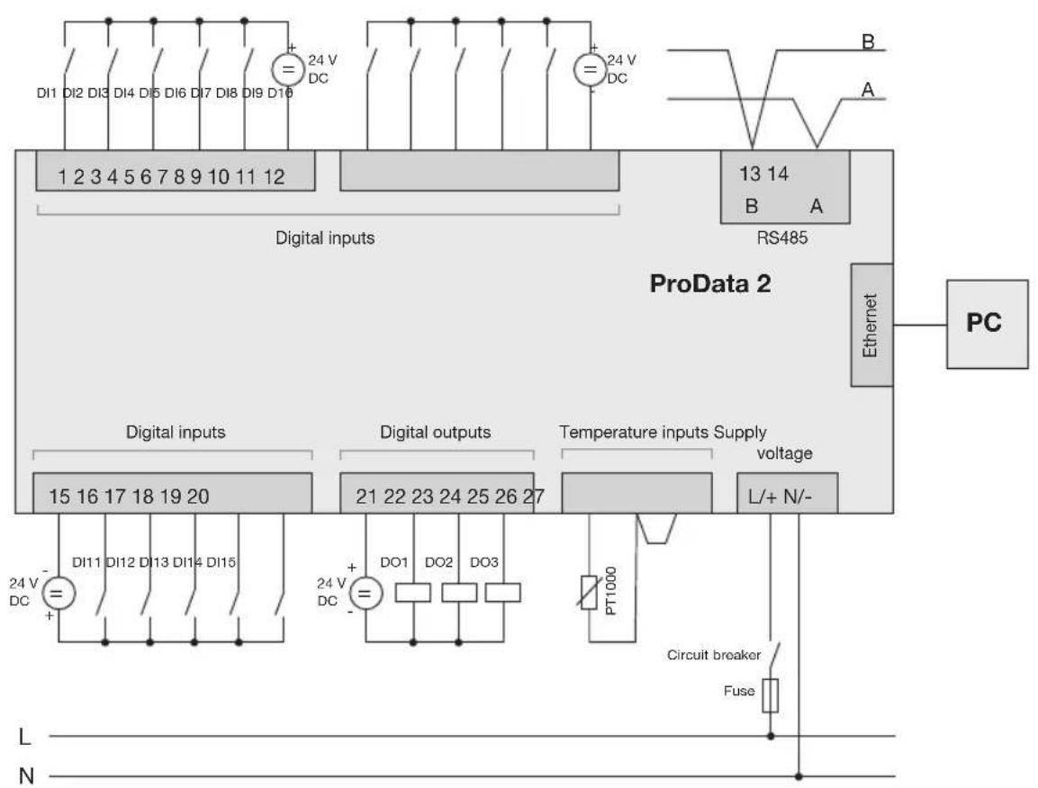
Connection example
flowchart
graph TD
    subgraph ProData_2
        A["Di1 DI2 DI3 DI4 DI5 DI6 DI7 DI8 DI9 D10 1 2 3 4 5 6 7 8 9 10 11 12"] --> B["Digital inputs"]
        C["RS485"] --> D["Digital outputs"]
        E["Di11 DI12 DI13 DI14 DI15"] --> F["Digital inputs"]
        G["DI15 15 16 17 18 19 20"] --> H["Digital outputs"]
        I["DI11 24 V DC"] --> J["DO1 DO2 DO3"]
        K["DO1 DO2 DO3"] --> L["PT1000"]
        M["Circuit breaker"] --> N["Fuse"]
        O["L"] --> P["N"]
    end
    subgraph Digital Inputs
        Q["24 V DC"] --> R["+"]
        S["24 V DC"] --> T["+"]
        U["24 V DC"] --> V["+"]
    end
    subgraph Digital Outputs
        W["21 22 23 24 25 26 27"] --> X["+"]
        Y["DO1 DO2 DO3"] --> Z["+"]
    end
    subgraph Temperature Inputs Supply
        AA["TVoltage"] --> AB["L/+ N/-"]
    end
    subgraph Ethernet
        AC["PC"] --> AD["A"]
        AE["B"] --> AF["A"]
    end


- ProData 2
- Table of contents
- General 3
- Inspection on receipt 6
- Product description 8
- Installation 14
- Configuration and commissioning 28
- Service and maintenance 41
- Procedure in the event of faults 45
- Technical data 46
- Connection example 52
- General
- Copyright
- Trademarks
- Disclaimer
- Comments on the operating manual
- Meaning of the symbols
- Dangerous voltage!
- Caution!
- Note!
- Instructions for use
- Concerning these operating instructions
- Inspection on receipt
- Scope of delivery of ProData 2
- Available accessories
- Product description
- Proper use
- ProData 2 features
- Parameterisation
- GridVis network analysis software
- GridVis features
- Connection variants
- Installation
- Position of installation
- Supply voltage
- Before connecting the supply voltage, make sure that the voltage and frequency correspond to the details on the ratings plate.
- RS485 interface
- Termination resistors
- Screening
- Cable type
- Maximum cable length
- Bus structure
- Ethernet interface
- Digital outputs
- Digital inputs
- S0 pulse input
- S0 plug-in module
- Temperature measurement input
- Device address (RS485)
- DIP switch S1
- Service button S2
- LED device status
- Configuration and commissioning
- Connecting the supply voltage
- Device termination (termination resistor)
- Baud rate
- Functional attributes
- Pulse counters
- Pulse value:
- S0 power values
- Events
- Clock
- Timer
- Recordings
- Data memory
- Rate conversion
- Ethernet
- Modbus gateway
- Service and maintenance
- Repairs
- Front film
- Disposal
- Service
- Device calibration
- Calibration
- Battery
- Replacing the battery
- Procedure
- Firmware update
- Dimension diagrams
- FCC Compliance Statement
Brand : Janitza
Model : ProData 2
Category : Meter