H4M-D1 - Security Camera Avigilon - Free user manual and instructions
Find the device manual for free H4M-D1 Avigilon in PDF.


| Product Type | Security Camera |
| Model | H4M-D1 |
| Brand | Avigilon |
| Lens | 2.8mm, F1.2, IR Corrected |
| Horizontal Field of View | 1.3MP: 110° (16:9); 2.0MP: 110° (16:9); 3.0MP: 100° (16:9) |
| Network Interface | 100Base-TX, RJ-45 |
| Power Source | PoE IEEE802.3af Class 2, 4W |
| Dimensions (L x W x H) | 73 mm x 73 mm x 52 mm (2.9" x 2.9" x 2.0") |
| Weight | 118 g (0.26 lbs) |
| Housing Material | Polycarbonate and aluminum |
| Operating Temperature | 0°C to 50°C (32°F to 122°F) |
| Storage Temperature | -30°C to 70°C (-22°F to 158°F) |
| Humidity | 0-95% non-condensing |
| Adjustment Range | 360° pan, -5° to 75° tilt, ±115° azimuth |
| Certifications | UL, cUL, CE, ROHS, WEEE, RCM, EAC, KC |
| Compliance | FCC Part 15 Class B, IC ICES-003, EN 55032 |
| ONVIF Compliance | Profile S (versions 1.02, 2.00) |
| Security Features | Password protection, HTTPS, 802.1x, digest authentication |
| Installation Requirements | Qualified personnel, UL Listed Class 2 power unit or PoE |
| Included Accessories | Surface mount adapter, bezel, screws, mounting template sticker |
| Cleaning Instructions | Use mild detergents; avoid abrasive cleaners |
| Warranty | See avigilon.com/warranty |
Frequently Asked Questions - H4M-D1 Avigilon
User questions about H4M-D1 Avigilon
0 question about this device. Answer the ones you know or ask your own.
Ask a new question about this device
Download the instructions for your Security Camera in PDF format for free! Find your manual H4M-D1 - Avigilon and take your electronic device back in hand. On this page are published all the documents necessary for the use of your device. H4M-D1 by Avigilon.
USER MANUAL H4M-D1 Avigilon
Installation Guide
Avigilon H4 Mini Dome Camera Models with Surface Mount Adapter:
1.3C-H4M-D1, 1.3C-H4M-D1-IR, 2.0C-H4M-D1, 2.0C-H4M-D1-IR, 3.0C-H4M-D1, 3.0C-H4M-D1-IR
Important Safety Information
This manual provides installation and operation information and precautions for the use of this device. Incorrect installation could cause an unexpected fault. Before installing this equipment read this manual carefully. Please provide this manual to the owner of the equipment for future reference.

This Warning symbol indicates the presence of dangerous voltage within and outside the product enclosure that may result in a risk of electric shock, serious injury or death to persons if you precautions are not followed.

This Caution symbol alerts the user to the presence of hazards that may cause minor or more injury to persons, damage to property or damage to the product itself if proper precautions are followed.

WARNING — Failure to observe the following instructions may result in severe injury or death
• Installation must be performed by qualified personnel only.
- Installation of the device must conform to all local codes.
- This product is intended to be supplied by a UL Listed Power Unit marked "Class 2" or "LPS" or "Limited Power" with output rated 12 VDC, 10W minimum, or Power over Ethernet (PoE) rated 4W min.
- Do not connect directly to a mains power system for any reason.

CAUTION — Failure to observe the following instructions may result in injury to persons or damage to the device.
- Do not expose the camera directly to high levels of x-ray, laser, or UV radiation. Direct exposure to high levels of x-ray, laser, or UV radiation may cause permanent damage to the image sensor
- Do not install near any heat sources such as radiators, heat registers, stoves, or other sources of heat.
- Do not subject the device cables to excessive stress, heavy loads or pinching.
- Do not open or disassemble the device. There are no user serviceable parts.
- Refer all device servicing to qualified personnel. Servicing may be required when the device has been damaged (such as from a liquid spill or fallen objects), has been exposed to rain or does not operate normally, or has been dropped.
- Do not use strong or abrasive detergents when cleaning the device body.
- Use only accessories recommended by Avigilon.
Regulatory Notices
This device complies with part 15 of the FCC Rules. Operation is subject to the following two cor (1) this device may not cause harmful interference, and (2) this device must accept any interference received, including interference that may cause undesired operation.
This Class B digital apparatus complies with Canadian ICES-003.
This equipment has been tested and found to comply with the limits for a Class B digital device, Part 15 of the FCC rules. These limits are designed to provide reasonable protection against harmful interference in a residential installation. This equipment generates, uses and can radiate radio frequency energy and, if not installed and used in accordance with the instructions, may cause harmful interference in radio communications. However, there is no guarantee that interference will not occur in a particular installation. If this equipment does cause harmful interference to radio or television reception, which is determined by turning the equipment off and on, the user is encouraged to try to correct the intake one or more of the following measures:
- Reorient or relocate the receiving antenna.
- Increase the separation between the equipment and the receiver.
- Connect the equipment into an outlet on a circuit different from that to which the receiver is connected.
- Consult the dealer or an experienced radio/TV technician for help.
Changes or modifications made to this equipment not expressly approved by Avigilon Corporation or parties authorized by Avigilon Corporation could void the user's authority to operate this equipment.
Disposal and Recycling Information
When this product has reached the end of its useful life, please dispose of it according to your environmental laws and guidelines.
Risk of fire, explosion, and burns. Do not disassemble, crush, heat above 100 °C (212 °F), or incin
European Union:

This symbol means that according to local laws and regulations your product should be disposed o separately from household waste. When this product reaches its end of life, take it to a collection designated by local authorities. Some collection points accept products for free. The separate collectic and recycling of your product at the time of disposal will help conserve natural resources and ens is recycled in a manner that protects human health and the environment.
Legal Notices
© 2019, Avigilon Corporation. All rights reserved. AVIGILON, the AVIGILON logo, AVIGILON CONTROL CENTER, and ACC are trademarks of Avigilon Corporation. ONVIF is a trademark of Onvif, Inc. Other or logos mentioned herein may be the trademarks of their respective owners. The absence of the and ® in proximity to each trademark in this document or at all is not a disclaimer of ownership trademark. Avigilon Corporation protects its innovations with patents issued in the United States of A and other jurisdictions worldwide (see avigilon.com/patents). Unless stated explicitly and in writing, no
license is granted with respect to any copyright, industrial design, trademark, patent or other intellect property rights of Avigilon Corporation or its licensors.
Disclaimer
This document has been compiled and published using product descriptions and specifications available the time of publication. The contents of this document and the specifications of the products discuss herein are subject to change without notice. Avigilon Corporation reserves the right to make any such changes without notice. Neither Avigilon Corporation nor any of its affiliated companies: (1) guarantees completeness or accuracy of the information contained in this document; or (2) is responsible for you of, or reliance on, the information. Avigilon Corporation shall not be responsible for any losses or (including consequential damages) caused by reliance on the information presented herein.
Avigilon Corporation
avigilon.com
PDF-H4MD1-A
Revision: 3 - EN
20191224
Table of Contents
Overview .6....
Cover View 6
Surface Mounting Adapter View 7
Camera Body View 8
Installation 10
Required Tools and Materials...10....
Camera Package Contents 10
Using the Surface Mount Adapter...10....
Installing the Camera Base to the Mounting Adapter 12
Initializing a Camera Username and Password 12
Assigning an IP Address.... 13
Accessing the Live Video Stream.... 14
Aiming the Camera 14
Attaching the Bezel 16
Configuring the Camera 16
For More Information.... 17
Connection Status LED Indicator 18
Removing the Camera from the Mounting .Adapter 19
Resetting to Factory Default Settings 20
Setting the IP Address Using the ARP/Ping...Method 21
Specifications 22
Limited Warranty and Technical Support 24
Overview
Note: Be careful not to scratch the camera. The resulting marks or fingerprints may affect the overall image quality. Keep the protective covers on the outside of the camera until the complete.
Cover View

1. Camera body
The main body of the camera, including the internal mechanisms for aiming the camera.
2. Surface mount bezel
Used to protect the camera latch, the camera internals, and the surface mounting adapter.
Surface Mounting Adapter View
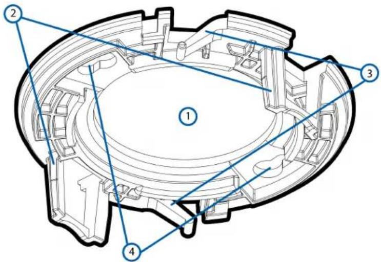
- Cable entry hole
An entry hole for the cables required for camera operation.
- Camera attachment slots
Slots that the camera housing clips are inserted into to attach the camera body to the surface mounting adapter.
- Bezel attachment clips
Clips to hold the bezel in place.
- Mounting holes
Holes for mounting the surface mounting adapter to the ceiling or wall.
Camera Body View

1. Ethernet port
Accepts power and Ethernet connection to the network.
The camera can only be powered by Power over Ethernet (PoE). Server communication and in data transmission also occur over this connection.
2. Camera housing clips
Clips that attach the camera body to the mounting adapter.
3. Locking latch
Orange-colored latch that locks the camera in place after the camera has been aimed. For information, see Aiming the Camera on page 14.
4. Camera lens
The lens is behind the protective dome.
- Infrared illuminator (optional)
The infrared illuminator is available on selected models.
- Connection status LED indicator
Provides information about device operation. For more information, see Connection Status LED Indicator on page 18.
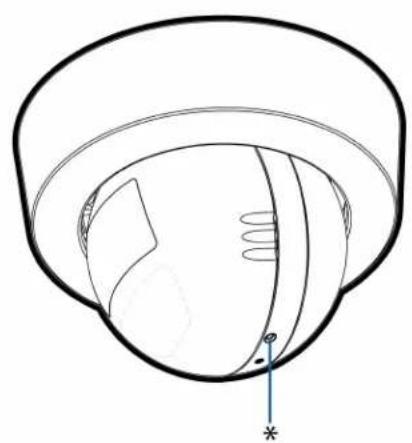
- Firmware revert button
Used to reset the camera. For more information, see Resetting to Factory Default Settings on page 20.
- Serial number tag
Provides the serial number and MAC address for the camera.
Installation
Required Tools and Materials
The following tools are required to complete the installation but are not included in the package:
• No. 2 Phillips screwdriver — for attaching camera to an electrical box or mounting surface.
Camera Package Contents
Ensure the package contains the following:
- Avigilon H4 Mini Dome Camera (H4M-D), the "camera".
• Surface mounting template sticker
• 2 screws and anchors for solid walls
• Surface mount adapter
• Surface mount bezel
Using the Surface Mount Adapter
The camera is provided with a surface mount adapter that can be mounted to a wall or ceiling.
If the camera needs to be installed in a different way, use one of the other mounting adapter c refer to their installation manuals for more information.
- Low-profile in-ceiling mounting adapter
- Gray (H4M-MT-DCIL1)
- Black (H4M-MT-DCIL1-BL)
Perform the following steps if the required cables are coming from inside the mounting surface and camera will be mounted immediately over the cable hole. Use this procedure on surfaces that can drilled into, and when the cables should be kept out of sight.
Perform the following steps to mount the surface adapter to mounting surface:
- Use the mounting template to drill two mounting holes into the mounting surface and drill the entry hole.

-
Pull the required Ethernet cable through the cable entry hole.
-
Drive two screws to fasten the mounting adapter to the mounting surface.

Installing the Camera Base to the Mounting Adapter
Note: Be careful not to scratch or touch the dome bubble. The resulting marks or fingerprints may affect the overall image quality. Keep the protective covers on the outside of the until the installation is complete.
After you install the mounting adapter, mount the camera base to the adapter, using the following
- Connect the Ethernet port attached to the camera to the Ethernet cable that was pulled thrc adapter.
The connection status LED indicator will turn on once a network link has been established.
- Position the camera in the mounting adapter, reinserting the connected cable through the cable hole.
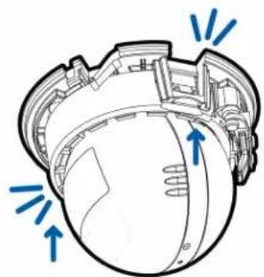
- Align the camera housing clips on the camera base to the camera attachment retainers on the mounting adapter. Press the camera base into the mounting adapter. The camera base clicks place and is held securely.

Initializing a Camera Username and Password
Cameras manufactured after January 1, 2020, do not have a default username or password and will factory default state.
Important: You must create a user with administrator privileges before the camera is operational.
The first user can be created using any of the following methods:
- Camera's Web Interface: enter the camera's IP address in a web browser to access the web interface. If the camera is in the factory default state you will be redirected to the Add a page to create the first user. For more information, see the Avigilon High Definition H4 and H5 IP Camera Web Interface User Guide.
- Camera Configuration Tool version 1.4.4 or later: cameras discovered in the factory default state will be identified by ⚠️. Select the Admin Users tab to create the first user. For more information, see the Avigilon Camera Configuration Tool User Guide.
- USB Wi-Fi Adapter: when connecting a camera in the factory default state, you will be redirected to the Create Administrator User page to create the first user. For more information, see Avigilon USB Wi-Fi Adapter System User Guide.
- Avigilon Control Center software version 7.4 or later, or version 6.14.12 or later: when connecting a camera in the factory default state, the client software will ask you to create a new user. For information, see the Avigilon Control Center Client User Guide.
- Avigilon Blue service v3.0 or later: when adding a camera you will be asked to create a new user for cameras in the factory default state. For more information, see the Avigilon Blue Subscriber or Dealer User Guides.
Tip: If you are connecting your Avigilon camera to a 3rd party VMS, you will need to set up the first user through the camera's Web Interface, Camera Configuration Tool, or USB Wifi A you connect to the 3rd party VMS.
Assigning an IP Address
The device automatically obtains an IP address when it is connected to a network.
Note: If the device cannot obtain an IP address from a DHCP server, it will use Zero Configuration Networking (Zeroconf) to choose an IP address. When set using Zeroconf, the IP a 169.254.0.0/16 subnet.
The IP address settings can be changed using one of the following methods:
• Device's web browser interface: http://
- Network Video Management software application (for example, the Avigilon Control Center™ software).
- ARP/Ping method. For more information, see Setting the IP Address Using the ARP/Ping Method on page 21.
Note:
Depending on the manufacture date of your camera, you will have one of the two
log in for the first time:
- Cameras manufactured after January 1, 2020: these cameras do not have a d or password and will be in a factory default state. You must create a user with administrator privileges before the camera is operational. For more information, see Initializing a Camera Username and Password on page 12.
- Cameras manufactured before January 1, 2020: login to the camera using the username of administrator with no password. It is recommended that you password after your first login.
Accessing the Live Video Stream
Live video stream can be viewed using one of the following methods:
- Web browser interface: http://< camera IP address>/.
- Network Video Management software application (for example, the Avigilon Control Center™ software).
Note:
Depending on the manufacture date of your camera, you will have one of the two log in for the first time:
- Cameras manufactured after January 1, 2020: these cameras do not have a d or password and will be in a factory default state. You must create a user with administrator privileges before the camera is operational. For more information, see Initializing a Camera Username and Password on page 12.
- Cameras manufactured before January 1, 2020: login to the camera using the username of administrator with no password. It is recommended that you password after your first login.
Aiming the Camera
Note: When you are aiming the camera, reference the live stream for the camera.
- Unlock the orange locking latch on the camera base if it is already locked. The lens should pointing in the general direction of the intended view.
The arrow indicator between the optical window and the camera base indicates the top of th
- Start with the arrow indicator as close to the mounting adapter as possible. Make pan adjust (see number 1 in the image below) until the lens is pointed in the intended direction. Then make the necessary tilt (see number 2 in the image below) and azimuth (see number 3 in the image below) adjustments until the live view is adjusted to your satisfaction.

- Swivel the locking latch to lock it into the closed position.

- In the camera web browser interface or the Avigilon Control Center software, adjust the came Image and Display settings.
Attaching the Bezel
After you lock the camera in place, attach the bezel to the mounting adapter, by completing the steps:
- Locate the two raised slots on the inner side of the bezel.
- Place the bezel up against the mounting adapter with the raised slots slightly to the left of mounting clips on the mounting adapter.
- Place the bezel up against the mounting adapter with the raised slots slightly to the left of mounting clips on the mounting adapter.

- Rotate the bezel clockwise until it snaps into place.

Configuring the Camera
Once installed, use one of the following methods to configure the camera:
- If you have the USB Wifi Adapter, you can access the mobile web interface to configure the camera. For more information, see Avigilon USB Wi-Fi Adapter System User Guide.
- If you have installed multiple cameras, you can use the Avigilon Camera Configuration Tool to configure common settings. For more information, see the Avigilon Camera Configuration Tool User Guide.
- If the camera is connected to the Avigilon Control Center system, you can use the client software to configure the camera. For more information, see the Avigilon Control Center Client User Guide.
- If the camera is connected to a third-party network management system, you can configure the camera's specialty features in the camera's web browser interface. For more information, see th Avigilon High Definition H4 and H5 IP Camera Web Interface User Guide.
For More Information
Additional information about setting up and using the device is available in the following guides:
• Avigilon Control Center Client User Guide
- Web Interface User Guide — Avigilon High Definition H4 and H5 IP Cameras
• Avigilon Camera Configuration Tool User Guide
- Designing a Site with Avigilon Video Analytics
These guides are available on help.avigilon.com and on the Avigilon website: avigilon.com/support-and-downloads.
Connection Status LED Indicator
Once connected to the network, the Connection Status LED indicator will display the progress in cc to the Network Video Management software.
The following table describes what the LED indicator shows:
| Connection | State | Connection LED | Status Indicator | Description |
| Obtaining IP Address | One short flash every second | Attempting to obtain an IP address. | ||
| Discoverable | Two | short flashes every second | Obtained an Network Video | IP address but not connected to the Management software. |
| Upgrading Firmware | Two short flashes and one long flash every second | Updating the firmware. |
Connected On Connected to the Network Video Management software or an ACC™ Server. The default connected setting can be changed to Off using the camera's web user interface. For more information see the Avigilon High Definition H4 and H5 IP Camera Web Interface User Guide.
Removing the Camera from the Mounting Adap
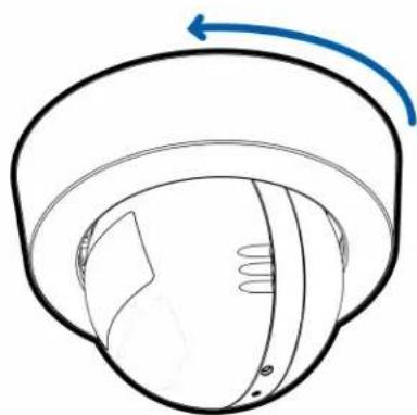
- Twist the bezel counter-clockwise until it releases. Some force will be required to release the and you will hear a click as it is released.
- Pinch the camera housing clips in the attachment slots to release the camera body from the mount and pull the camera out of the mount.
Resetting to Factory Default Settings
If the device no longer functions as expected, you can choose to reset the device to its factory settings.
Use the firmware revert button to reset the device. The firmware revert button is shown in the fc diagram:
-
Ensure the device is powered on.
-
Using a straightened paperclip or similar tool, gently press and hold the firmware revert button
-
Release the button after three seconds.

CAUTION — Do not apply excessive force. Inserting the tool too far may damage the came
Setting the IP Address Using the ARP/Ping Me
Complete the following steps to configure the camera to use a specific IP address:
Note: The ARP/Ping Method will not work if the Disable setting static IP address through ARP/Ping method check box is selected in the camera's web browser interface. For more information, see the Avigilon High Definition H4 and H5 IP Camera Web Interface User Guide.
- Locate and make note of the MAC Address (MAC) listed on the Serial Number Tag for refer
- Open a Command Prompt window and enter the following commands:
a. arp -s
For example: arp -s 192.168.1.10 00-18-85-12-45-78
b. ping -1 123 -t
For example: ping -l 123 -t 192.168.1.10
- Reboot the camera.
- Close the Command Prompt window when you see the following message:
Reply from
Specifications
Camera
| Lens 2.8mm, F1.2, IR Corrected | |
| HFOV (Angle of View) | 1.3 MP: (5:4) 74°; (16:9) 110°2.0 MP: (5:4) 74°; (16:9) 110°3.0 MP: (5:4) 94°; (16:9) 100°, (4:3) 100° |
| Network | |
| Network 100Base-TX | |
| Cabling Type CAT5 | |
| Connector RJ-45 | |
| ONVIF® ONVIF compliant with version 1.02, 2.00, Profile S (www.onvif.org) | |
| Security Password protection, HTTPS encryption, digest authentication, WS authentication, user access log, 802.1x port based authentication | |
| Protocols IPv4, HTTP, HTTPS, SOAP, DNS, NTP, RTSP, RTCP, RTP, TCP, UDP, IGMP, ICMP, DHCP, Zeroconf, ARP | |
| Streaming Protocols RTP/UDP, RTP/UDP multicast, RTP/RTSP/TCP, RTP/RTSP/HTTP/TCP, RTP/RTSP/HTTPS/TCP, HTTP | |
| Device Management SNMP v2cProtocols SNMP v3 | |
| Mechanical | |
| Dimensions Surface Mount: 73 mm x 73 mm x 52 mm (2.9" x 2.9" x 2.0")L x W x H | |
| Camera Weight withH4M-D1 - 118 g (0.26 lbs)Surface MountingBracket | |
| Body Polycarbonate and aluminum | |
| Housing Polycarbonate | |
| Finish Cool grey, black | |
| Adjustment Range 360° pan, -5° to 75° tilt, ±115° azimuth | |
| Electrical | |
| Power Consumption 4 W | |
Power Source PoE: IEEE802.3af Class 2 compliant
| RTC Backup Battery 3V manganese lithium | |
| Environmental | |
| Operating Temperature | 0 °C to 50 °C (32 °F to 122 °F) |
| Storage Temperature | -30 °C to 70 °C (-22 °F to 158 °F) |
| Humidity 0-95% non-condensing | |
| Certifications | |
| Certifications/ Directives | UL, cUL, CE, ROHS, WEEE, RCM, EAC, KC |
| Safety UL 62368-1, CSA 62368-1, IEC/EN 62368-1, IEC 62471 | |
| Environmental Indoor Applications | |
| Electromagnetic Emissions | FCC Part 15 Subpart B Class B, IC ICES-003 Class B, EN 55032 6-3, EN 61000-3-2, EN 61000-3-3, KN 32 |
| Electromagnetic Immunity | EN 55024, EN 61000-6-1, EN 50130-4, KN 35 |
Limited Warranty and Technical Support
Avigilon warranty terms for this product are provided at avigilon.com/warranty.
Warranty service and technical support can be obtained by contacting Avigilon Technical Support: avigilon.com/contact-us/.


- INSTALLATION GUIDE
- IMPORTANT SAFETY INFORMATION
- REGULATORY NOTICES
- DISPOSAL AND RECYCLING INFORMATION
- EUROPEAN UNION
- LEGAL NOTICES
- DISCLAIMER
- TABLE OF CONTENTS
- OVERVIEW .6
- INSTALLATION 10
- CONNECTION STATUS LED INDICATOR 18
- REMOVING THE CAMERA FROM THE MOUNTING .ADAPTER 19
- RESETTING TO FACTORY DEFAULT SETTINGS 20
- SETTING THE IP ADDRESS USING THE ARP/PING...METHOD 21
- SPECIFICATIONS 22
- LIMITED WARRANTY AND TECHNICAL SUPPORT 24
- OVERVIEW
- COVER VIEW
- CAMERA BODY
- SURFACE MOUNT BEZEL
- SURFACE MOUNTING ADAPTER VIEW
- CAMERA BODY VIEW
- ETHERNET PORT
- CAMERA HOUSING CLIPS
- LOCKING LATCH
- CAMERA LENS
- INSTALLATION
- REQUIRED TOOLS AND MATERIALS
- CAMERA PACKAGE CONTENTS
- USING THE SURFACE MOUNT ADAPTER
- INSTALLING THE CAMERA BASE TO THE MOUNTING ADAPTER
- INITIALIZING A CAMERA USERNAME AND PASSWORD
- ASSIGNING AN IP ADDRESS
- NOTE
- ACCESSING THE LIVE VIDEO STREAM
- AIMING THE CAMERA
- ATTACHING THE BEZEL
- CONFIGURING THE CAMERA
- FOR MORE INFORMATION
- CONNECTION STATUS LED INDICATOR
- REMOVING THE CAMERA FROM THE MOUNTING ADAP
- RESETTING TO FACTORY DEFAULT SETTINGS
- SETTING THE IP ADDRESS USING THE ARP/PING ME
- SPECIFICATIONS
- LIMITED WARRANTY AND TECHNICAL SUPPORT
Brand : Avigilon
Model : H4M-D1
Category : Security Camera