
KEW3123A - Meter Kyoritsu - Free user manual and instructions
Find the device manual for free KEW3123A Kyoritsu in PDF.


| Product Type | Insulation Resistance Tester |
| Brand | Kyoritsu |
| Model | KEW3123A |
| DC Test Voltage | 5000 V and 10000 V |
| Measuring Ranges | 0-5 GΩ / 2-200 GΩ (automatic low range), 0-10 GΩ / 4-400 GΩ (automatic high range) |
| Accuracy | ±5% of reading (0.2~100 GΩ) at 23°C; ±10% of reading (0.2~100 GΩ) at -10°C~+40°C; for higher ranges ±10% or ±20% |
| Output Voltage Accuracy | 5000 V ±5% (0.2~100 GΩ), 10000 V ±5% (0.4~200 GΩ) |
| Power Source | 8 x AA (R6P) batteries or equivalent |
| Battery Life | Approx. 6 hours continuous operation at maximum load |
| Dimensions | 200 x 140 x 80 mm |
| Weight | Approx. 1 kg (including batteries) |
| Operating Temperature | -10°C to +40°C |
| Storage Temperature | -20°C to +60°C |
| Safety Features | Drip proof construction, high voltage warning, auto discharge after test |
| Key Features | Automatic range selection, dual color-coded scales with LED indicators, guard terminal for surface leakage elimination, continuous measurement lock, mechanical zero adjustment |
| Included Accessories | Hard carrying case M-9158, test leads (line probe M-7165A, earth cord M-7224A, guard cord M-7225A), pickel type prod M-8019 |
| Optional Accessories | Recorder adapter MODEL8324, line cord with alligator clip M-7168A |
| Maintenance | Clean with damp cloth and mild detergent; avoid solvents; replace batteries when pointer not in BATT. GOOD area |
| Spare Parts | Replacement metal tips for line probe: MODEL8252 (standard), MODEL8254 (straight), MODEL8019 (pickel) |
| Standards Compliance | Manufactured to quality standards; specifications subject to change without notice |
Frequently Asked Questions - KEW3123A Kyoritsu
User questions about KEW3123A Kyoritsu
0 question about this device. Answer the ones you know or ask your own.
Ask a new question about this device
Download the instructions for your Meter in PDF format for free! Find your manual KEW3123A - Kyoritsu and take your electronic device back in hand. On this page are published all the documents necessary for the use of your device. KEW3123A by Kyoritsu.
USER MANUAL KEW3123A Kyoritsu
KEW3121A, 3122A KEW3123A

- Safety warnings ....1
- Features ...... 2
- Specifications 3 \~ 4
- Instrument Layout ....5
- Operating Instructions ......6
5-1. Mechanical Zero Adjustment 6
5-2. Battery Check 6
5-3. Insulation Resistance Measurement 7
5-4. Continuous Measurement 7
5-5. Use of Guard Terminal 8
-
Battery Replacement 9
-
Accessories and options 9
7-1. Metal part for Line Probe, and replacement 9
7-2. How to use the adaptor for recorder 10
-
How to fix the Meter to the Hard case 11
-
Cleaning Meter Cover 12
1. Safety warnings
Please read through these operating instructions before using the instrument to avoid any dangers such as electrical shock and to ensure safe operation of the instrument.
Pay particular attention to all WARNING and CAUTION in this instruction manual. WARNING indicates warnings to avoid electrical shock and CAUTION indicates cautions to avoid damage to the instrument.
WARNING
● This instrument cannot test live conductors. Ensure that the circuit to be tested is powered off before performing a test.
● Never open the Battery cover or remove the Instrument panel during a measurement.
- Confirm that the Rotary switch is at the OFF position, and then connect the test leads.
- Do not attempt to make measurement in the presence of flammable gasses. Otherwise, the use of the instrument may cause sparking, which can lead to an explosion.
● Never attempt to make any measurement if any abnormal conditions, such as a broken cover or exposed metal parts are present on the Instrument or test leads.
- Set the Function switch to OFF position after use, and ensure the Test button is released and unlocked.
CAUTION
- Do not expose the instrument to direct sunlight, high temperatures, humidity or dew.
- Never leave the instrument in the environment of 60°C or higher temperatures.
- Do not use the instrument if it or test lead is wet.
- Remove the batteries if the instrument is to be stored and will not be in use for a long period.
- Use a damp cloth with neutral detergent or water for cleaning the instrument. Do not use abrasives or solvents.
2. Features
● Battery powered, the instruments test insulation up to 100000MΩ at 2500V for KEW 3121A, 200000MΩ at 5000V for KEW 3122A and 200GΩ at 5000V and 400GΩ at 10000V for KEW 3123A.
- Suited for heavy duty electrical maintenance and servicing of industrial installations, cables, transformers, generators and switchgear where high voltage insulation tests are required.
- Dual scales for low and high ranges which change automatically. Colour coded scales for easy reading plus LED's that illuminate in matching colour.
- Drip proof construction. The case is sealed with rubber gaskets to protect internal circuit against rain.
- Hard carrying case furnished as standard accessory. Houses both instrument and test leads in compact form. Made of plastic, it is highly water resistant.
- Designed for low power consumption. Since the maximum current consumption is 90mA eight pieces of 1.5V SUM-3 (or equivalent) permit about 6 hours of continuous operation even when the instrument is used on maximum load or twice longer on minimum load.
- Rated output voltage is maintained down to 100MΩ for KEW 3121A, 200MΩ for KEW 3122A and 0.2GΩ/0.4GΩ for KEW 3123A. This permits accurate measurements of low insulation resistance.
- Optional adapter MODEL8324 is available for connection to recorder and enables cable insulation monitoring.
3. Specifications
| KEW 3121A | KEW 31 | ||
| DC Test Voltage | 2500V | 5000 V | |
| Measuring Ranges | 0~2000MΩ/1000~100000MΩ(automatic change) | 0~5000 M2000~ 20(automatic ch | |
| Accuracy | Insulation Resistance | ±5% of reading(100~50000MΩ)±10% of readingor 0.5% of scale length(ranges other thanlisted above)at 23°C ±5°C | ±5% of re(200~ 10±10% of reor 0.5% of sc(ranges clisted abat 23°C ± |
| ±10% of reading(100~50000MΩ)±20% of readingor 1.0% of scale length(ranges other thanlisted above)at -10°C~+40°C | ±10% of re(200~ 10±20% of reor 1.0% of sc(ranges clisted abat -10°C ~ | ||
| Output Voltage | 2500V ±5%(100~50000MΩ) | 5000V ±(200~ 10 | |
| Operating Temperature & Humidity | -10°C ~ | ||
| Storage Temperature & Humidity | -20°C ~ | ||
| Insulation Resistance | 1000MΩ max./ 10 | ||
| Withstand Voltage | 5000V AC for one n | ||
| Dimensions | 20 | ||
| Weight | Approx. 1k | ||
| Power Source | 8 pcs of Re | ||
| Accessories | Hard Carrying Case:M-9158 Test Leads(Line Probe:M-7165A, EarthCord:M-7224A, Guard Cord:M-7225A) | ||
| Optional accessories | Line cord with alligator clip : M-7168AOptional adapter : M-8324Pickel type prod:M-8019 | ||
| A KEW 3123A | |||
| 00 MΩ/~ 200000MΩtic change) | 0~5GΩ/2~200GΩ(automatic change) | 0~10GΩ/4~400GΩ(automatic change) | |
| of reading(~ 100000MΩ)of readingof scale lengthges other thaned above)C ±5°C | ±5% of reading(0.2~100GΩ)±10% of readingor 0.5% of scale length (ranges other thanlisted above)at 23°C ±5°C | ±5% of reading(0.4~200GΩ)±10% of readingor 0.5% of scale length (ranges other thanlisted above)at 23°C ±5°C | |
| of reading(~ 100000MΩ)of readingof scale lengthges other thaned above)°C ~+40°C | ±10% of reading(0.2~100GΩ)±20% of readingor 1.0% of scale length (ranges other thanlisted above)at -10°C~+40°C | ±10% of reading(0.4~200GΩ)±20% of readingor 1.0% of scale length (ranges other thanlisted above)at -10°C~+40°C | |
| / ±5%)~ 100000MΩ) | 5000V ±5%(0.2~100GΩ) | 10000V ±5%(0.4~200GΩ) | |
| C ~+40°C at 85% max. relative humidity | |||
| C ~+60°C at 90% max. relative humidity | |||
| / 1000V between electrical circuit & housing case | |||
| uit & housing case | |||
| 200(L)×140(W)×80(D)mm | |||
| . 1kg (including batteries) | |||
| if R6P (AA) battery or equivalent | |||
| Hard Carrying Case:M-9158 Batteries, Test Leads (Line Probe:M-7165A, Earth Cord:M-7224A, Guard Cord:M-7225A) Pickel type prod:M-8019 | |||
| Line cord with alligator clip : M-7168AOptional adapter : M-8324 | |||
4. Instrument Layout

natural_image
Technical line drawing of a rectangular device with internal components and a labeled section (8), no readable text or symbols present.① Line Terminal
② Guard Terminal
③ Earth Terminal
④ LED's for High & Low Range Indication
⑤ Press to Test Button
⑥ Function Switch
⑦ Meter Movement Zero Adjust
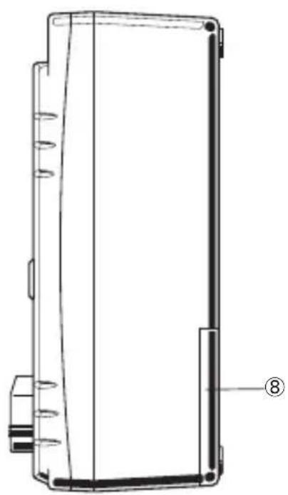
⑧ Battery Compartment Cover
⑨ Line Probe (Red)
⑩ Earth Cord (Black)
⑪ Guard Cord (Green)
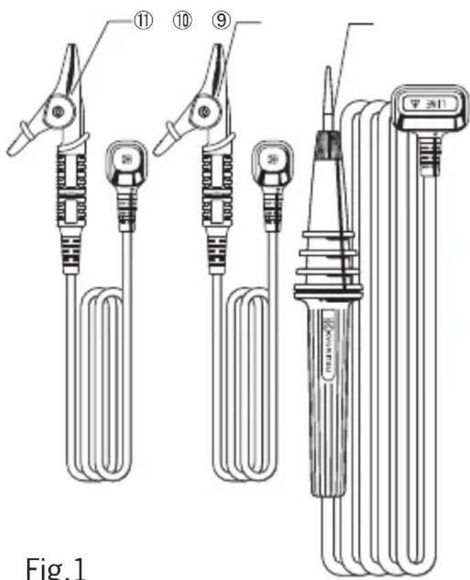
Fig.1
5. Operating Instructions
CAUTION:
BE CAREFUL ABOUT HIGH VOLTAGE PRESENT ACROSS LINE AND EARTH TERMINALS OF INSTRUMENT WHEN PRESS TO TEST BUTTON IS OPERATED. MAKE SURE TO EARTH CIRCUIT UNDER TEST. ALWAYS CONNECT EARTH TERMINAL OF INSTRUMENT TO EARTH. THE BUZZER WILL KEEP SOUNDING DURING INSULATION RESISTANCE MEASUREMENT.
5-1. Mechanical Zero Adjustment
With the function switch set at OFF position, adjust the meter pointer to “∞ mark” on the scale. Use a screwdriver to turn the zero adjust screw located at the center of the front panel.
5-2. Battery Check
With the function switch set at BATT. CHECK position, operate the press to test button. The batteries are good when the pointer stays in BATT. GOOD area or to the right of this area. If not, replace them.
Note: Refrain from holding down or locking the press to test button during this test as it will result in current consumption larger than insulation resistance measurement while the batteries are still new.
5-3. Insulation Resistance Measurement
With the function switch set at OFF position, always connect the circuit under test to earth. Attach the test lead to the earth terminal of the instrument and connect to the earthed side of the circuit under test. With the function switch set at 2500V and 5000V for KEW 3121A and 3122A or 5000V or 10000V for KEW 3123A, connect the black earth code to the earth terminal (EARTH) and place the line probe in contact with the circuit under test and press the Test button. When the green LED illuminates, read insulation resistance on the outer scale (for high range). Use the inner scale where the red LED illuminates. For insulation testing at 5000V and 10000V, read the black and red scales respectively (for KEW 3123A). After a test, release the press to test button and wait for several seconds without disconnecting the line probe from the circuit tested. This is intended to discharge the charge stored in the circuit tested.
5-4. Continuous Measurement
Make sure that the circuit under test is earthed and that the test lead attached to the earth terminal of the instrument is connected to the earthed side of the circuit under test. Push the press to test button and turn clockwise to lock for continuous measurement. When making this measurement, good care must be taken against the high voltage continuously present across the line and earth terminals of the instrument.
Note: Make certain that the circuit under test does not include components which will be damaged by the high voltage applied.
5-5. Use of Guard Terminal
When measuring the insulation resistance of a cable, leakage current flowing on the surface of cable jacket and the current flowing inside the insulator are mixed and may cause error in insulation resistance value. In order to prevent such error, wind a conductive wire around the point where leakage current flows. Then connect it to the Guard terminal as shown in below Fig .2. This is to move out the surface leakage resistance of the cable insulation to measure only the volume resistance of insulator. Make sure to use the Guard cord supplied with this instrument to connect the instrument to Guard terminal.
Connect the terminals with reference to the following figure of an equivalent circuit.
* Wind a protective wire, any conductive bare wires are ok, around the point where leakage currents flow. Then connect it to the Guard terminal as follows.

Fig.2
* It is possible to move out the surface leakage resistance of the insulation and measure only the volume resistance by using the Guard terminal. This is helpful when performing tests in humid air.
6. Battery Replacement
Remove the battery compartment cover by loosening the screw located on the back of the housing case. Replace the whole battery pack. Alkaline batteries are recommended where the instrument is used at a temperature below the freezing point. The ordinary manganese batteries will deteriorate below the freezing point.
7. Accessories and options
7-1. Metal part for Line Probe, and replacement
(1) Tip metal parts
MODEL8252: Standard Prod (straight type, with molded parts)
MODEL8254: Straight Type Prod
MODEL8019: Pickel Type Prod (accessory)
To be used to hook the instrument.
Note:Option KEW3121A, KEW3122A
(2) How to replace it
Turn the Line probe counterclockwise to remove the attached tip metal. Put the tip metal you want to use to the hexagon socket and turn it to clockwise together with the tip of probe, and tight up screws.

7-2. How to use the adaptor for recorder
MODEL8324 is the adaptor for recorder for output current measurement. Connect it as shown in the below Fig.3.
Output is DC10mV when current of 1 µA is flowing.

Fig.3
8. How to fix the Meter to the Hard case
Please follow the instructions below to fix MODEL9159 main unit to MODEL9158 Hard case with Dual lock fastener.
- Place a hard board beneath the Hard case.
The board should be located under the fastener attached to the Hard case.

natural_image
Close-up of a mechanical component with a grid pattern and two arrows pointing to it, no visible text or symbols.Dual lock fastener
A hard board should be placed in the location as indicated by dotted lines.
- Put the unit in place, and then press down the sides of the unit so that the mushroom-shaped stems on the fastener are engaged each other with audible snap sound.

Pressing down the sides of unit (as indicated by arrow marks) engages the stems on the fastener.
9. Cleaning Meter Cover
This earth tester is managed by our company's quality standard and is delivered in the best condition after passed the inspection. But in the dry time of winter static electricity sometimes builds up on the meter cover due to the characteristic of plastic.
When the pointer deflects by touching the surface of this tester or zero adjustment can not be made, do not try to make measurement.
When static electricity builds up on the meter cover and affects the meter reading, use a cloth dampened with off-the-shelf anti-statics agent or detergent to wipe the meter cover surface.
DISTRIBUTOR
Kyoritsu reserves the rights to change specifications or designs described in this manual without notice and without obligations.

natural_image
Abstract black arrow symbol pointing left within a rectangular border (no text or numbers)


- Safety warnings
- WARNING
- CAUTION
- Features
- Specifications
- Instrument Layout
- Operating Instructions
- CAUTION:
- 5-1. Mechanical Zero Adjustment
- 5-2. Battery Check
- 5-3. Insulation Resistance Measurement
- 5-4. Continuous Measurement
- 5-5. Use of Guard Terminal
- Battery Replacement
- Accessories and options
- 7-1. Metal part for Line Probe, and replacement
- 7-2. How to use the adaptor for recorder
- How to fix the Meter to the Hard case
- Cleaning Meter Cover
Brand : Kyoritsu
Model : KEW3123A
Category : Meter