
SG10RS-L - Uncategorized Sungrow - Free user manual and instructions
Find the device manual for free SG10RS-L Sungrow in PDF.


| Product Type | 1-Phase PV Grid-Connected Inverter |
| Model | SG10RS-L |
| Dimensions (W x H x D) | 525 mm x 365 mm x 170 mm |
| Weight | 18 kg |
| Rated AC Output Power | 10000 W |
| Max. AC Output Power | 10000 VA |
| Max. PV Input Voltage | 600 V |
| MPP Voltage Range | 40 V – 560 V |
| Number of MPP Trackers | 3 |
| Max. Efficiency | 97.8% |
| European Efficiency | 97.4% |
| Protection Class | I |
| Ingress Protection Rating | IP65 |
| Overvoltage Category | DC II / AC III |
| Cooling Method | Natural Cooling |
| Display | LED Digital Display & LED Indicator |
| Communication Interface | WLAN |
| DC Connection Type | MC4 Compatible Connector (max. 6 mm²) |
| AC Connection Type | OT Terminal (max. 16 mm²) |
| Operating Temperature Range | -25°C to +60°C |
| Safety Features | AFCI, PID Zero, Grid Monitoring, DC Switch, Surge Protection Type II |
| Mounting Method | Wall-Mounting Bracket |
| Warranty | Standard manufacturer warranty (see manual for details) |
Frequently Asked Questions - SG10RS-L Sungrow
User questions about SG10RS-L Sungrow
0 question about this device. Answer the ones you know or ask your own.
Ask a new question about this device
Download the instructions for your Uncategorized in PDF format for free! Find your manual SG10RS-L - Sungrow and take your electronic device back in hand. On this page are published all the documents necessary for the use of your device. SG10RS-L by Sungrow.
USER MANUAL SG10RS-L Sungrow
1-Phase PV Grid-Connected Inverter
SG7.5RS-L / SG8.0RS-L / SG9.0RS-L / SG10RS-L
natural_image
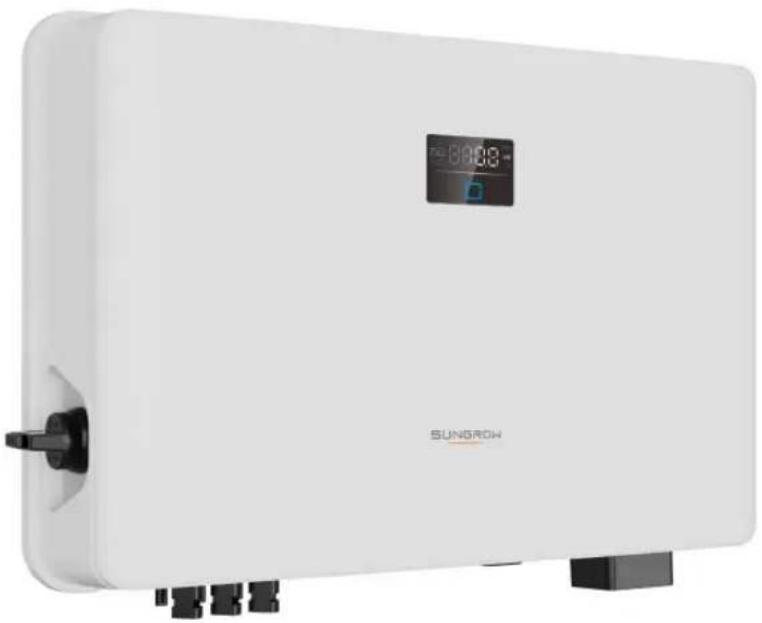
White outdoor water heater with digital display and black connectors (no visible text or symbols)All Rights Reserved
All Rights Reserved
No part of this document can be reproduced in any form or by any means without the prior written permission of Sungrow Power Supply Co., Ltd (hereinafter "SUNGROW").
Trademarks
SUNGROW and other Sungrow trademarks used in this manual are owned by SUNGROW.
All other trademarks or registered trademarks mentioned in this manual are owned by their respective owners.
Software Licenses
- It is prohibited to use data contained in firmware or software developed by SUNGROW, in part or in full, for commercial purposes by any means.
- It is prohibited to perform reverse engineering, cracking, or any other operations that compromise the original program design of the software developed by SUNGROW.
About This Manual
The manual mainly contains the product information, as well as guidelines for installation, operation, and maintenance. The manual does not include complete information about the photovoltaic (PV) system. Readers can get additional information at www.sungrowpower.
com or on the webpage of the respective component manufacturer.
Validity
This manual is valid for the following model of low-power grid-connected PV string inverters:
- SG7.5RS-L
- SG8.0RS-L
- SG9.0RS-L
- SG10RS-L
It will be referred to as "inverter" hereinafter unless otherwise specified.
Target Group
This manual is intended for professional technicians who are responsible for installation, operation, and maintenance of inverters, and users who need to check inverter parameters.
The inverter must only be installed by professional technicians. The professional technician is required to meet the following requirements:
- Know electronic, electrical wiring and mechanical expertise, and be familiar with electrical and mechanical schematics.
- Have received professional training related to the installation and commissioning of electrical equipment.
- Be able to quickly respond to hazards or emergencies that occur during installation and commissioning.
- Be familiar with local standards and relevant safety regulations of electrical systems.
- Read this manual thoroughly and understand the safety instructions related to operations.
How to Use This Manual
Please read this manual carefully before using the product and keep it properly at a place for easy access.
All contents, pictures, marks, and symbols in this manual are owned by SUNGROW. No part of this document may be reprinted by the non-internal staff of SUNGROW without written authorization.
Contents of this manual may be periodically updated or revised, and the actual product purchased shall prevail. Users can obtain the latest manual from support.sungrowpower.com or sales channels.
Security Declaration
For details on the product's network security vulnerability response process and vulnerability disclosure, please visit the following website: https://en.sungrowpower.com/security-vulnerability-management.
For more information on network security, please refer to the user manual of the communication module or the Data Logger that comes with the product.
Symbols
This manual contains important safety instructions, which are highlighted with the following symbols, to ensure personal and property safety during usage, or to help optimize the product performance in an efficient way.
Please carefully understand the meaning of these warning symbols to better use the manual.
! DANGER
Indicates high-risk potential hazards that, if not avoided, may lead to death or serious injury.
WARNING
Indicates moderate-risk potential hazards that, if not avoided, may lead to death or serious injury.
CAUTION
Indicates low-risk potential hazards that, if not avoided, may lead to minor or moderate injury.
NOTICE
Indicates potential risks that, if not avoided, may lead to device malfunctions or financial losses.

"NOTE" indicates additional information, emphasized contents or tips that may be helpful, e.g., to help you solve problems or save time.
Contents
All Rights Reserved ....I
About This Manual....II
1 Safety Instructions ....1
1.1 Unpacking and Inspection ....2
1.2 Installation Safety ....3
1.3 Electrical Connection Safety....3
1.4 Operation Safety ....5
1.5 Maintenance Safety....5
1.6 Disposal Safety ....7
2 Product Description ....8
2.1 System Introduction......8
2.2 Product Introduction....9
2.3 Symbols on Product.... 11
2.4 LED Panel 12
2.5 Circuit Diagram 13
2.6 Function Description ....14
3 Unpacking and Storage 20
3.1 Unpacking and Inspection ....20
3.2 Inverter Storage 20
4 Mechanical Mounting 22
4.1 Safety During Mounting....22
4.2 Location Requirements ....23
4.2.1 Installation Environment Requirements....24
4.2.2 Carrier Requirements 26
4.2.3 Angle Requirements....26
4.2.4 Clearance Requirements ......27
4.3 Installation Tools....27
4.4 Moving the Inverter....29
4.5 Installing the Inverter....29
5 Electrical Connection ....32
5.1 Safety Instructions ....32
5.2 Terminal Description ....34
5.3 Electrical Connection Overview 35
5.4 External Protective Grounding Connection ....37
5.4.1 External Protective Grounding Requirements 38
5.4.2 Connection Procedure....38
5.5 AC Cable Connection 39
5.5.1 AC Side Requirements 39
5.5.2 Connecting the AC Cable 40
5.6 DC Cable Connection ....43
5.6.1 PV Input Configuration 45
5.6.2 Assembling the PV Connectors ....46
5.6.3 Installing the PV Connectors 47
5.7 Communication Connection ....48
5.7.1 WLAN Communication 48
6 Commissioning 49
6.1 Inspection Before Commissioning....49
6.2 Powering on the System 49
6.3 App Preparation ....50
6.4 Creating a Plant....50
6.5 Initializing the Device ....58
6.6 Configuring the Plant 62
7 iSolarCloud App 66
7.1 Brief Introduction ......66
7.2 Installing App ....66
7.3 Account Registration....67
7.4 Login 68
7.4.1 Requirements ......68
7.4.2 Login Procedure 69
7.5 Initial Settings....71
7.6 Function Overview....71
7.7 Home 72
7.8 Run Information....73
7.9 Records....74
7.10 More....77
7.10.1 System Parameters....78
7.10.2 Operation Parameters 78
7.10.3 Power Regulation Parameters....79
7.10.4 Communication Parameters....84
7.10.5 Firmware Update ....84
8 System Decommissioning 86
8.1 Disconnecting the Inverter....86
8.2 Dismantling the Inverter 86
8.3 Disposal of Inverter....87
9 Troubleshooting and Maintenance 88
9.1 Troubleshooting 88
9.2 Maintenance 95
9.2.1 Maintenance Notices....95
9.2.2 Routine Maintenance 97
10 Appendix 98
10.1 Technical Data....98
10.2 Quality Assurance ....102
10.3 Contact Information 103
1 Safety Instructions
When installing, commissioning, operating, and maintaining the product, strictly observe the labels on the product and the safety requirements in the manual. Incorrect operation or work may cause:
- Injury or death to the operator or a third party.
- Damage to the product and other properties.
WARNING
- Do not perform any operation on the product (including but not limited to, handling, installing, powering on, or maintaining the product, performing electrical connection, and working at heights) in harsh weather conditions, such as thunder and lightning, rain, snow, and Level 6 or stronger winds. SUNGROW shall not be held liable for any damage to the device due to force majeure, such as earthquakes, floods, volcanic eruptions, mudslides, lightning strikes, fires, wars, armed conflicts, typhoons, hurricanes, tornadoes, and other extreme weathers.
- In case of fire, evacuate from the building or product area and call the fire alarm. Re-entry into the burning area is strictly prohibited under any circumstances.
NOTICE
- Tighten the screws with the specified torque using tools when fastening the product and terminals. Otherwise, the product may be damaged. And the damage caused is not covered by the warranty.
- Learn how to use tools correctly before using them to avoid hurting people or damaging the device.
- Maintain the device with sufficient knowledge of this manual and use proper tools.
i
- The safety instructions in this manual are only supplements and cannot cover all the precautions that should be followed. Perform operations considering actual onsite conditions.
- SUNGROW shall not be held liable for any damage caused by violation of general safety operation requirements, general safety standards, or any safety instruction in this manual.
- When installing, operating, and maintaining the product, comply with local laws and regulations. The safety precautions in this manual are only supplements to local laws and regulations.
- During the product transport, installation, wiring, maintenance, etc., the materials and tools prepared by users must meet the requirements of applicable local laws and regulations, safety standards, and other specifications. SUNGROW shall not be held liable for any damage to the product caused by the adoption of materials and tools that fail to meet the above-mentioned requirements.
- Operations on the product, including but not limited to, handling, installing, wiring, powering on, maintenance, and use of the product, must not be performed by unqualified personnel. SUNGROW shall not be held liable for any damage to the product resulting from operations done by unqualified personnel.
- Where the transport of the product is arranged by users, SUNGROW shall not be held liable for any damage to the product that is caused by users themselves or the third-party transport service providers designated by the users.
- SUNGROW shall not be held liable for any damage to the product caused by the negligence, intent, fault, improper operation, and other behaviors of users or third-party organizations.
- SUNGROW shall not be held liable for any damage to the product arising from reasons unrelated to SUNGROW.
1.1 Unpacking and Inspection
! WARNING
- Check all safety signs, warning labels and nameplates on devices.
- The safety signs, warning labels and nameplates must be clearly visible and cannot be removed or covered before the device is decommissioned.
NOTICE
After receiving the product, check whether the appearance and structural parts of the device are damaged, and check whether the packing list is consistent with the actual ordered product. If there are problems with the above inspection items, do not install the device and contact your distributor first. If the problem persists, contact SUNGROW in time.
1.2 Installation Safety
! DANGER
- Make sure there is no electrical connection before installation.
- Before drilling, avoid the water and electricity wiring in the wall.
CAUTION
Improper installation may cause personal injury!
- If the product supports hoisting transport and is hoisted by hoisting tools, no one is allowed to stay under the product.
- When moving the product, be aware of the product weight and keep the balance to prevent it from tilting or falling.
NOTICE
Before operating the product, must check and ensure that tools to be used have been maintained regularly.
1.3 Electrical Connection Safety
! DANGER
- Before electrical connections, please make sure that the inverter is not damaged, otherwise it may cause danger!
- Before electrical connections, please make sure that the inverter switch and all switches connected to the inverter are set to "OFF", otherwise electric shock may occur!
! DANGER
The PV string will generate lethal high voltage when exposed to sunlight.
- Operators must wear proper personal protective equipment during electrical connections.
- Must ensure that cables are voltage-free with a measuring instrument before touching DC cables.
- Respect all safety instructions listed in relevant documents about PV strings.
- The inverter must not be connected to a PV string that requires positive or negative grounding.
! DANGER
Danger to life due to a high voltage inside the inverter!
- Be sure to use special insulation tools during cable connections.
- Note and observe the warning labels on the product, and perform operations strictly following the safety instructions.
- Respect all safety instructions listed in this manual and other pertinent documents.
! WARNING
Damage to the product caused by incorrect wiring is not covered by the warranty.
- Electrical connection must be performed by professionals.
- All cables used in the PV generation system must be firmly attached, properly insulated, and adequately dimensioned.
WARNING
- Check the positive and negative polarity of the PV strings, and connect the PV connectors to corresponding terminals only after ensuring polarity correctness.
- During the installation and operation of the inverter, please ensure that the positive or negative poles of PV strings do not short-circuit to the ground. Otherwise, an AC or DC short-circuit may occur, resulting in equipment damage. The damage caused by this is not covered by the warranty.
- Do not connect any load between the inverter and the AC circuit breaker directly connected to it, so as to prevent the switch from tripping by mistake.
- Determine the specifications of AC circuit breakers strictly in compliance with the applicable local laws and regulations and safety standards or the recommendation by SUNGROW. Otherwise, the switch may not open in time in the event of something abnormal, which may then lead to safety incidents.
NOTICE
Comply with the safety instructions related to PV strings and the regulations related to the local grid.
1.4 Operation Safety
! DANGER
When routing cables, ensure a distance of at least 30 mm between the cables and heat-generating components or areas to protect the insulation layer of cables from aging and damage.
When the product is working:
- Do not touch the product enclosure.
- It is strictly forbidden to plug and unplug any connector on the inverter.
- Do not touch any wiring terminal of the inverter. Otherwise, electric shock may occur.
- Do not disassemble any parts of the inverter. Otherwise, electric shock may occur.
- It is strictly forbidden to touch any hot parts of the inverter (such as the heat sink). Otherwise, it may cause burns.
- Do not connect or remove any battery. Otherwise, electric shock may occur.
- Do not connect or remove any PV string or any PV module in a string. Otherwise, electric shock may occur.
- If the inverter is equipped with a DC switch, do not operate it. Otherwise, it may cause device damage or personal injury.
Do not take other actions, such as setting parameters or cutting off power, during the process of inverter firmware update, to avoid update failure.
1.5 Maintenance Safety
! DANGER
Risk of inverter damage or personal injury due to incorrect service!
- Before maintenance, disconnect the AC circuit breaker on the grid side and then the DC switch. If a fault that may cause personal injury or device damage is found before maintenance, disconnect the AC circuit breaker and wait until the night before operating the DC switch. Otherwise, a fire inside the product or an explosion may occur, causing personal injuries.
• After the inverter is powered off for 10 minutes, measure the voltage and current with professional instrument. Only when there is no voltage nor current can operators who wear protective equipment operate and maintain the inverter. - Even if the inverter is shut down, it may still be hot and cause burns. Wear protective gloves before operating the inverter after it cools down.
! DANGER
Touching the power grid or the contact points and terminals on the inverter connected to the power grid may lead to electric shock!
- The power grid side may generate voltage. Always use a standard voltmeter to ensure that there is no voltage before touching.
CAUTION
To prevent misuse or accidents caused by unrelated personnel, post prominent warning signs or demarcate safety warning areas around the product.
NOTICE
To avoid the risk of electric shock, do not perform any other maintenance operations beyond those described in this manual. If necessary, contact your distributor first. If the problem persists, contact SUNGROW. Otherwise, the losses caused is not covered by the warranty.
NOTICE
- If the paint on the inverter enclosure falls or rusts, repair it in time. Otherwise, the inverter performance may be affected.
- Do not use cleaning agents to clean the inverter. Otherwise, the inverter may be damaged, and the loss caused is not covered by the warranty.
- As the inverter contains no parts that can be maintained, never open the enclosure of the inverter or replace any internal components without authorization. Otherwise, the loss caused is not covered by the warranty.
- Do not open the maintenance door in rainy or snowy weather. If it is inevitable, take proper protective measures to avoid the ingress of rainwater and snow into the maintenance compartment; otherwise, the product's operation may be affected.
- Before closing the maintenance door, check whether there is any object left inside the maintenance compartment, such as screws, tools, etc.
- It is recommended for users to use cable sheathing to protect the AC cable. If the cable sheathing is used, make sure it is positioned inside the maintenance compartment.
1.6 Disposal Safety
WARNING
Please scrap the product in accordance with relevant local regulations and standards to avoid property losses or casualties.
2 Product Description
2.1 System Introduction
The inverter is a transformerless 1-phase PV grid-connected inverter. As an integral component in the PV power system, the inverter is designed to convert the direct current power generated from the PV modules into grid-compatible AC current and feeds the AC current to the utility grid.
WARNING
- The inverter must only be operated with PV strings with class II protection in accordance with IEC 61730, application class A. It is not allowed for the positive pole or the negative pole of the PV strings to be grounded. This can cause damage to the inverter.
- Do not connect any local load between the inverter and the AC circuit breaker.
NOTICE
The inverter applies only to the scenarios described in this manual.
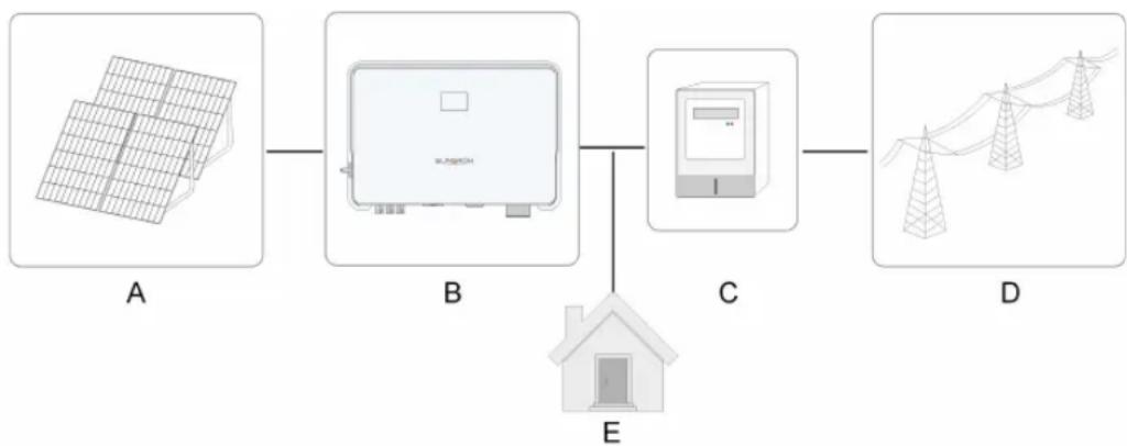
The intended usage of the inverter is illustrated in the following figure.
flowchart
graph LR
    A[" Solar Panel A "] --> B[" Device B "]
    B --> C[" Home E "]
    C --> D[" Power Tower D "]
figure 2-1 Inverter Application in PV Power System
| Item | Description | Note |
| A | PV strings | Compatible with monocrystalline silicon, polycrystalline silicon, and thin-film modules without grounding. |
| B | Inverter | SG7.5RS-L, SG8.0RS-L, SG9.0RS-L, SG10RS-L. |
| C | Metering device | Meter cupboard with power distribution system. |
| D | Utility grid | TT, TN-C, TN-S, TN-C-S. |
| E | Loads | House loads that consume electricity. |
The following figure shows the common grid configurations.
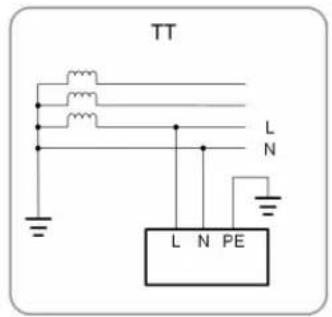
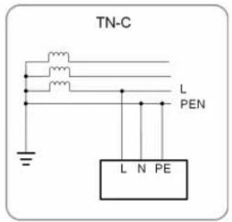
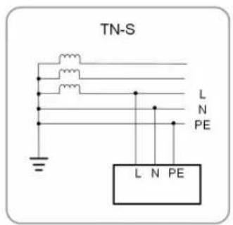
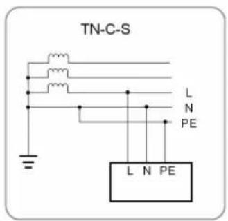
S005-G002
To meet the demand of users in different regions, connection to a split-phase grid system is supported for this inverter, as in the following way. Grounding detection function will not be available when the inverter is used in the split-phase grid system.

flowchart
graph LR
    FV --> Inversor
    Inversor --> CA
    Inversor --> L
    Inversor --> N
    Inversor --> L1
    Inversor --> N2
    CA --> L1
    L --> N
    N --> L2
    L1 --> Transformer
    N --> Transformer
    L2 --> Transformer
    Transformer --> L
2.2 Product Introduction
Model Description
The model description is as follows (take SG8.0RS—L as an example):
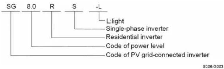
Appearance
The following figure shows the appearance of the inverter. The image shown here is for reference only. The actual product received may differ.
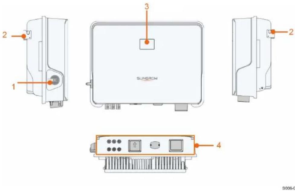
figure 2-2 Inverter Appearance
| No. | Name | Description |
| 1 | DC switch | To safely disconnect the DC circuit whenever necessary. |
| 2 | Hanger | Complement to the included wall mounting bracket for hanging the inverter. |
| 3 | LCD panel | The LCD screen indicates the running information and the LED indicator indicates the working state of the inverter. |
| 4 | Electrical connection area | DC terminals, AC terminal and communication terminals. |
Dimensions
The following figure shows the dimensions of the inverter.
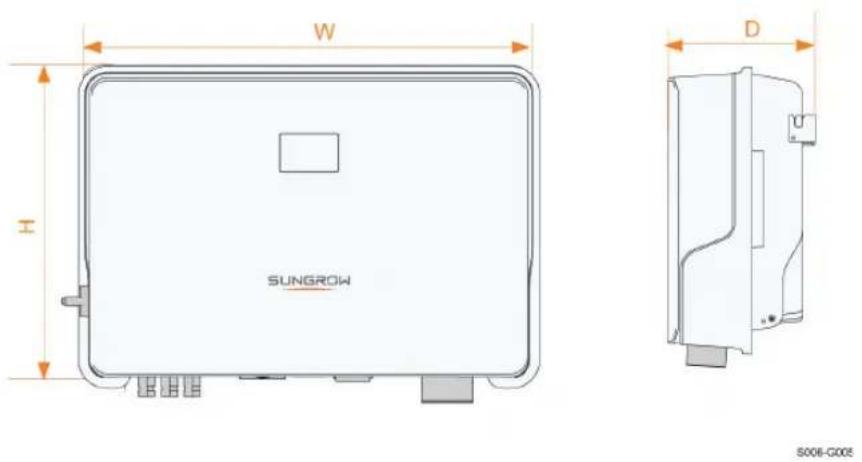
figure 2-3 Dimensions of the Inverter
Inverter Model W (mm) H (mm) D (mm)
SG7.5RS-L, SG8.0RS-L, SG9.0RS-L,
525 365 170
SG10RS-L
2.3 Symbols on Product
Symbol Explanation
 | Parameters on the DC side. |
 | Parameters on the AC on-grid side. |
 | Regulatory compliance mark. |
 | TÜV mark of conformity. |
 | CE mark of conformity.EU/EEA Importer. |
 | UKCA mark of conformity. |
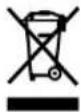 | Do not dispose of the inverter together with household waste. |
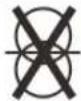 | The inverter does not have a transformer. |
 | Disconnect the inverter from all the external power sources before maintenance! |
 | Read the user manual before maintenance! |
| Symbol | Explanation | |
 | Burn danger due to the hot surface that may exceed 60°C. | |
 | Danger to life due to high voltages!Only qualified personnel can open and service the inverter. | |
 | 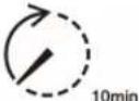 | Danger to life due to high voltages!Do not touch live parts for 10 minutes after disconnection from the power sources. |
 | External protective grounding terminal. |
* The table shown here is for reference only. The actual product received may differ.
* Users may also attach other warning signs as per the requirements of the local standards or installation specifications.
2.4 LED Panel
The LED panel with a display screen and an indicator is on the front of the inverter.
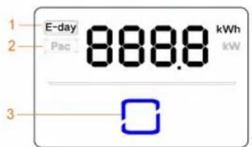
(a)
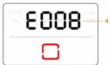
(b)
figure 2-4 LED Panel
(a) Normal state (b) Error state
| No. | Name | Description |
| 1 | E-day Today's energy yield. | |
| 2 | Pac | Current AC power. |
| 3 | LED indicator | To indicate the working state of the inverter.Touch it to switch the information in normal state or view multiple error codes in error state. |
| 4 | Error code | The error code in the figure is just an example. |
- In normal state, the E-day and Pac information will be displayed alternately. Also you can touch the LED indicator to switch the information.
- In error state, touch the LED indicator to view error codes.
- If there is no operation for 5 minutes, the display screen will be off. Touch the LED indicator to activate it.
table 2-1 State description of the LED indicator
| LED color State Definition | |||
 | On | The inverter is operating normally. | |
| Flashing | The inverter is at standby or startup state (not feeding power into the grid). | ||
| Blue | |||
 | On | A system fault has occurred. | |
| Red | |||
 | Off | Both the AC and DC sides are powered down. | |
| Gray | |||
WARNING
Voltage may still be present in AC side circuits after the indicator is off. Pay attention to the electricity safety during operating.
2.5 Circuit Diagram
The following figure shows the main circuit of the inverter.
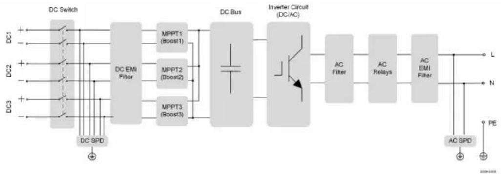
flowchart
graph LR
    A["DC Switch"] --> B["DC EMI Filter"]
    B --> C["MPPT1 (Boost1)"]
    B --> D["MPPT2 (Boost2)"]
    B --> E["MPPT3 (Boost3)"]
    C --> F["DC Bus"]
    D --> F
    E --> F
    F --> G["Inverter Circuit (DC/AC)"]
    G --> H["AC Filter"]
    H --> I["AC Relays"]
    I --> J["AC EMI Filter"]
    J --> K["L"]
    J --> L["N"]
    J --> M["PE"]
    N["DC1"] --> A
    O["DC2"] --> A
    P["DC3"] --> A
    Q["DC SPD"] --> A
figure 2-5 Circuit Diagram (SG10RS-L for example)
- DC Switches can safely disconnect the PV input when necessary to ensure the safe operation of the inverter and the safety of personnel.
- The DC SPD provides a discharge circuit for the DC side overvoltage to prevent it from damaging the internal circuits of the inverter.
- EMI filters can filter out the electromagnetic interference inside the inverter to ensure that the inverter meets the requirements of electromagnetic compatibility standards.
- The MPPT is used to ensure a maximum power from PV arrays at different PV input conditions.
- The Inverter Circuit converts the DC power into grid-compliant AC power and feeds it into the grid.
- The AC filter filters the output AC component of high frequency to ensure that the output current meets the grid requirements.
- The AC relay isolates the AC output of the inverter from the grid, making the inverter safe from the grid in case of inverter failure or grid failure.
- The AC SPD provides a discharge circuit for the AC side overvoltage to prevent it from damaging the internal circuits of the inverter.
! DANGER
If the lightning level exceeds the protection level of the product, surge protection and overvoltage protection may fail, resulting in electric shock and fatal injury!
2.6 Function Description
Basic Function
- Conversion function
The inverter converts the DC power from the PV array to the AC power, in conformity with the grid requirements.
- Data storage
The inverter logs running information, error records, etc.
- Parameter configuration
The inverter provides various parameter configurations for optimal operation.
Parameters can be set via the iSolarCloud App or the cloud server.
- Communication interface
The inverter is equipped with two communication interfaces. The communication device can be connected to the inverter via both interfaces.
After communication connection is established, users can view inverter information, operational data and can set inverter parameters through the iSolarCloud.

It is recommended to use the communication module from SUNGROW. Using a device from other companies may lead to communication failure or other unexpected damage.
- Protection Function
Several protective functions are integrated in the inverter, including short circuit protection, grounding insulation resistance monitoring, residual current protection, grid monitoring, DC overvoltage/overcurrent protection, etc.
DRM ("AU"/"NZ")
The DRM function is only applicable to a single inverter.
The inverter provides terminals for connecting to a Demand Response Enabling Device (-DRED). After the connection, the DRED asserts demand response modes (DRMs). The inverter detects and initiates a response to all supported demand response modes listed in the following table.
table 2-2 Demand Response Mode Explanation
Mode Explanation
DRM0 The inverter is in the state of shutdown.
Feed-in Limitation
Set the feed-in limitation value via iSolarCloud App. When the smart energy meter detects that the export power is greater than the limit value, the inverter will reduce the output power within the specified range.
PID Zero
The PID Zero function is applicable for both PV and DC-coupled PV plus storage systems. It can suppress PID during the day and intelligently repair PV panels damage caused by PID at night, by relieving or alleviating PV array voltage bias to PV-.
The traditional inverter needs boost circuit to extend the efficient generation time during the day, and break the symmetry of the PV array to the ground voltage, making it closer to the negative electrode. In addition, if the traditional inverter runs at night, the PV array to ground voltage is always limited to the lowest voltage point of the system, which increases the risk of PID.
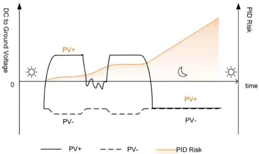
line
| Time Point | PV+ (DC to Ground Voltage) | PV- (DC to Ground Voltage) | PID Risk | | ---------- | -------------------------- | -------------------------- | -------- | | Peak | High | Low | Low | | Mid | Low | Very Low | Medium | | Peak | High | Low | High | | Mid | Low | Very Low | Medium | | Peak | High | Low | High |figure 2-6 PID Risk of Traditional Inverters
The following figure is the PID risk of the inverter equipped with PID Zero, it prevents the PV array voltage from approaching PV-, reduces the risk of PID during daily operation and repairs PV panels caused by PID at night. Details can be found in the PID Zero White Paper, which can be obtained on www.sungrowpower.com or from your distributor.
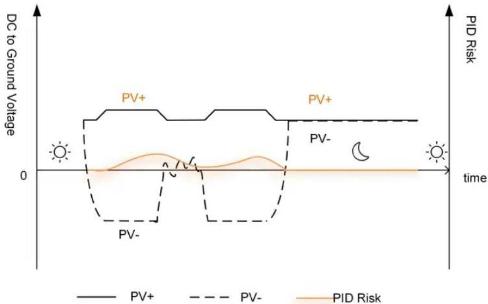
figure 2-7 PID Risk of Inverters Equipped with PID Zero
! DANGER
Keep the DC switch "ON" in the PID Zero process. During the process, there is voltage hazard between inverter / PV panels live conductors and ground. Do not touch any of them.

- When the PID Zero function is enabled, there will be a power consumption of less than 30 W in the PID Zero process.
AFCI Function (Optional)
- AFCI activation
This function can be enabled to detect whether serial fault arc occurs in the loop between PV array and inverter.
- AFCI self-test
This function is intended to test whether AFCI works as normal.
- Clear AFCI Alarm
When the inverter detects the AFCI alarm, it stops working. Clear the AFCI alarm so that the inverter can restart the detection.
- Protection Coverage
Two types of classifications are defined for AFCI protection, "F (Full coverage)" and "P (-Partial coverage)". Full coverage protection ("F") is available for this inverter.
• AFPE
This inverter is equipped with a fully integrated AFPE, which is implemented within the inverter connected to the PV array and makes use of the enclosure and terminals of the inverter.
• Method of Implementation
Two implementation options are available for AFCI protection, "D" and "I". "D" represents "Distributed detection system", where the AFPE comprises more than one device. The devices may be standalone devices or partially integrated within the power conversion equipment (PCE). While "I" represents "PCE integrated device", where the AFPE is implemented within a PCE connected to the PV array and makes use of the enclosure and terminals of the PCE. "I" is adopted for this inverter.
- Reconnection Method
Three reconnection methods are available for this inverter:
1 Manual reconnection
Reconnection can only be performed manually after arc interruption. You can log in via local access to the iSolarCloud App, and choose More→ Settings→ Operation Parameters→ AFCI Parameters→ Clear AFCI Alarm; after clearing the fault alarm, restart the device.
2 Remote manual reconnection
Reconnection can be performed via remote access to the AFPE after interruption. You can log in to iSolarCloud remotely. Then, find the target plant and choose Settings; select the device, and choose Advanced Settings→ Power Control→ Clear AFCI Alarm. After clearing the fault alarm, restart the device.
3 Automatic reconnection
Reconnection can be performed automatically after arc interruption.
Rule: Upon detecting a real arc fault, the device will report a fault and shut down. Within the day, for the 1st to 4th arc fault alarm, the device will shut down for 10 minutes, then the alarm will be cleared and the device will restart; when the 5th or more arc fault is reported, the device will shut down and not resume operation on that day.
In the event of the 1st to 4th arc fault alarm, ARM is powered off and restarted, and the device can restart and reconnect to the grid normally, with the fault count reset to "0". When the 5th arc fault is detected, if ARM is powered off and restarted due to external environment factors, the device will report a fault and shut down, with the fault count changing to "1"; after 10 minutes, the fault alarm will be cleared and the device will restart. If ARM is not powered off when the 5th or more arc fault is reported, you need to clear the fault manually to get the device restarted and reconnected to the grid normally; in this case, the fault count will be reset to "0". Or you can wait for the fault to be cleared automatically the next day, in which case the fault count will change to "1". See "Manual reconnection" and "Remote manual reconnection" for instructions on how to clear the fault alarm manually.
- AFCI protection configuration.
The AFCI configuration of each inverter model is shown in the table below.
| Model SG8.0/9.0/10RS-L | |
| Classification F-I-AFPE-1-1/1/1-3 | |
| Number of monitored strings per input port | 1 |
| Number of input ports per channel | 1 |
| Number of monitored channels 3 | |
| Rated channel current 16 | |
| Maximum current per input port | 16 |
| Rated interruption current | 16 |
NOTICE
For SG8.0RS-L inverters, if two PV strings are connected to PV2, enable PV2 Branch Connector to activate arc fault detection for PV2; if only one string is connected to PV2, this is not required. To configure this setting, open iSolarCloud and choose "Inverter→Settings→Operation Parameters→String Detection→PV2 Branch Connector".

The fault arc detection function meets the standard requirements, please test under the working conditions as required by the standard.
3 Unpacking and Storage
3.1 Unpacking and Inspection
The product is thoroughly tested and strictly inspected before delivery. Nonetheless, damage may still occur during shipping. For this reason, please conduct a thorough inspection after receiving the product.
- Check the packing case for any visible damage.
- Check the scope of delivery for completeness according to the packing list.
- Check the inner contents for damage after unpacking.
Contact SUNGROW or the transport company in case of any damage or incompleteness, and provide photos to facilitate services.
Do not dispose of the original packing case. It is recommended to store the device in the original packing case when the product is decommissioned.
NOTICE
- After receiving the product, check whether the appearance and structural parts of the device are damaged, and check whether the packing list is consistent with the actual ordered product. If there are problems with the above inspection items, do not install the device and contact your distributor first. If the problem persists, contact SUNGROW in time.
- If any tool is used for unpacking, be careful not to damage the product.
3.2 Inverter Storage
Proper storage is required if the inverter is not installed immediately.
- Store the inverter in the original packing case with the desiccant inside.
- The storage temperature must be always between -30^ and +70^ , and the storage relative humidity must be always between 0 and 95% , non-condensing.
- In case of stacking storage, the number of stacking layers should never exceed the limit marked on the outer side of the packing case.
- The packing case should be upright.
- If the inverter needs to be transported again, pack it strictly before loading and transporting it.
-
Do not store the inverter in places susceptible to direct sunlight, rain, and strong electric field.
-
Do not place the inverter in places with items that may affect or damage the inverter.
- Store the inverter in a clean and dry place to prevent dust and water vapor from eroding.
- Do not store the inverter in places with corrosive substances or susceptible to rodents and insects.
- Carry out periodic inspections. Inspection shall be conducted at least once every six months. If any insect or rodent bites are found, replace the packaging materials in time.
- If the inverter has been stored for more than a year, inspection and testing by professionals are required before it can be put into operation.
NOTICE
Please store the inverter according to the storage requirements. Product damage caused by failure to meet the storage requirements is not covered by the warranty.
4 Mechanical Mounting
WARNING
Respect all local standards and requirements during mechanical installation.
4.1 Safety During Mounting
! DANGER
Make sure there is no electrical connection before installation. Before drilling, avoid the water and electricity wiring in the wall.
WARNING
For specific requirements for the installation environment, see "4.2.1 Installation Environment Requirements". In case the environment where the product is installed does not meet the requirements, SUNGROW shall not be held liable for any property damage arising therefrom.
CAUTION
Improper handling may cause personal injury!
- When moving the product, be aware of its weight and keep the balance to prevent it from tilting or falling.
- Wear proper protective equipment before performing operations on the product.
- The bottom terminals and interfaces of the product cannot directly contact the ground or other supports. The product cannot be directly placed on the ground.
NOTICE
During installation, ensure that no device in the system causes it hard for the DC switch and the AC circuit breaker to act or hinders maintenance personnel from operating.
If drilling is required during installation:
- Wear goggles and protective gloves when drilling holes.
- Make sure to avoid the water and electricity wiring in the wall before drilling.
- Protect the product from shavings and dust.
4.2 Location Requirements
To a large extent, a proper installation location ensures safe operation, service life, and performance of the inverter.
- The inverter with protection rating IP65 can be installed both indoors and outdoors.
- The inverter should be installed at a height that allows easy viewing of the LED indicator panel, as well as easy electrical connection, operation and maintenance.
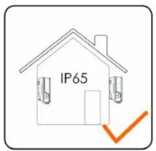
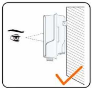
S006-1001
4.2.1 Installation Environment Requirements
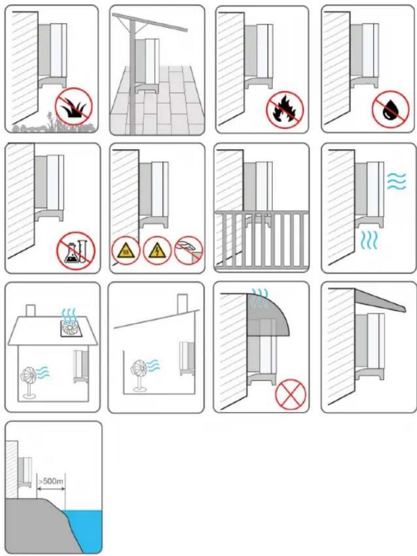
- If the inverter is installed in a place with lush vegetation, weed on a regular basis. In addition, the ground beneath the inverter needs to undergo certain treatment, such as laying cement or gravel, etc. (an area of 3m × 2.5m is recommended).
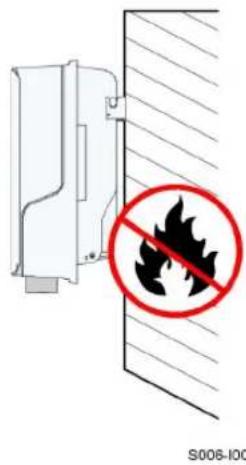
- Do not install the inverter in an environment with flammables, explosives, or smoke.
- Do not install the inverter in places prone to water leak, e.g., under the air-conditioner vent, the air vent, or the cable outlet window of the machine room, so as to prevent device damage or short circuit caused by intrusion of water.
- Do no install the inverter in a place with corrosives such as corrosive gas and organic solvent, etc.
- When the inverter is running, its surface may carry high voltages or get very hot. Do not touch it; otherwise, it may lead to burns or electric shocks.
-
Do not install the inverter in a place that is easy to reach for people.
-
If the inverter needs to be installed in a closed or semi-closed environment, please install additional heat dissipation or ventilation devices. Furthermore, while the inverter is operating, ensure the indoor ambient temperature does not exceed the outdoor ambient temperature. A semi-closed environment refers to a special space where natural ventilation is limited and gas or heat may easily accumulate, although it is not fully enclosed on all six sides.
- The installation site must have solid ground, free of rubber-like soils (which cannot be effectively compacted) or weak soils, and should not be prone to subsidence. Also, avoid low-lying areas where water or snow may easily accumulate. Ensure the site is located above the highest recorded water level in the area.
- Do not install the inverter in a position that could be flooded.
- To prevent vegetation or water on the ground from impacting inverter operation, if the space above meets the designated requirements, elevate the inverter to an appropriate height.
- Install the inverter in a place with shelter, so as to prevent it from getting impacted by direct sunlight and severe weather (e.g. snow, rain, and lightning). The inverter will derate in high temperatures for self-protection. If installed in a place directly exposed to sunlight, as the temperature rises, the inverter may witness power reduction.
- Good heat dissipation is very important to the inverter. Please install the inverter in a ventilated environment.
- If the inverter needs to be installed in a closed or semi-closed environment, please install additional heat dissipation or ventilation devices. Furthermore, while the inverter is operating, ensure the indoor ambient temperature does not exceed the outdoor ambient temperature. A semi-closed environment refers to a special space where natural ventilation is limited and gas or heat may easily accumulate, although it is not fully enclosed on all six sides.
- Please consult SUNGROW before installing inverters outdoors in areas prone to salt damage, which mainly are coastal areas within 500 meters of the coast. The sedimentation amount of salt spray is correlated to the characteristics of the seawater, sea winds, precipitation, air humidity, topography, and forest coverage in the adjacent sea areas, and there are substantial differences between different coastal areas.
- Do not install the inverter in an environment contaminated with chemicals such as halogen and sulfide.
- Do not install the inverter in an environment with vibration and strong electromagnetic field. Strong-magnetic-field environments refer to places where magnetic field strength measures over 30 A/m.
- In dusty environments such as places full of dust, smoke, or floc, particles may cling to the device's air outlet or heat sink, thus impacting its heat dissipation performance or even getting it damaged. Therefore, do not install the inverter in dusty environments. If the inverter has to be installed in such environments, please clean its fans and heat sink on a regular basis to ensure a good heat dissipation performance.
- The average temperature approximately 1 m around the inverter should be taken as its operating temperature. The temperature and humidity should meet the requirements below:

4.2.2 Carrier Requirements
The mounting structure where the inverter is installed must comply with local/national standards and guidelines. Ensure that the installation surface is solid enough to bear four times the weight of the inverter and is suitable for the dimensions of the inverter (e.g. cement walls, plasterboard walls, etc.).
Do not install the inverter on a carrier that may vibrate in resonance, so as to avoid making bigger noise.
The structure should meet the following requirements:
4.2.3 Angle Requirements
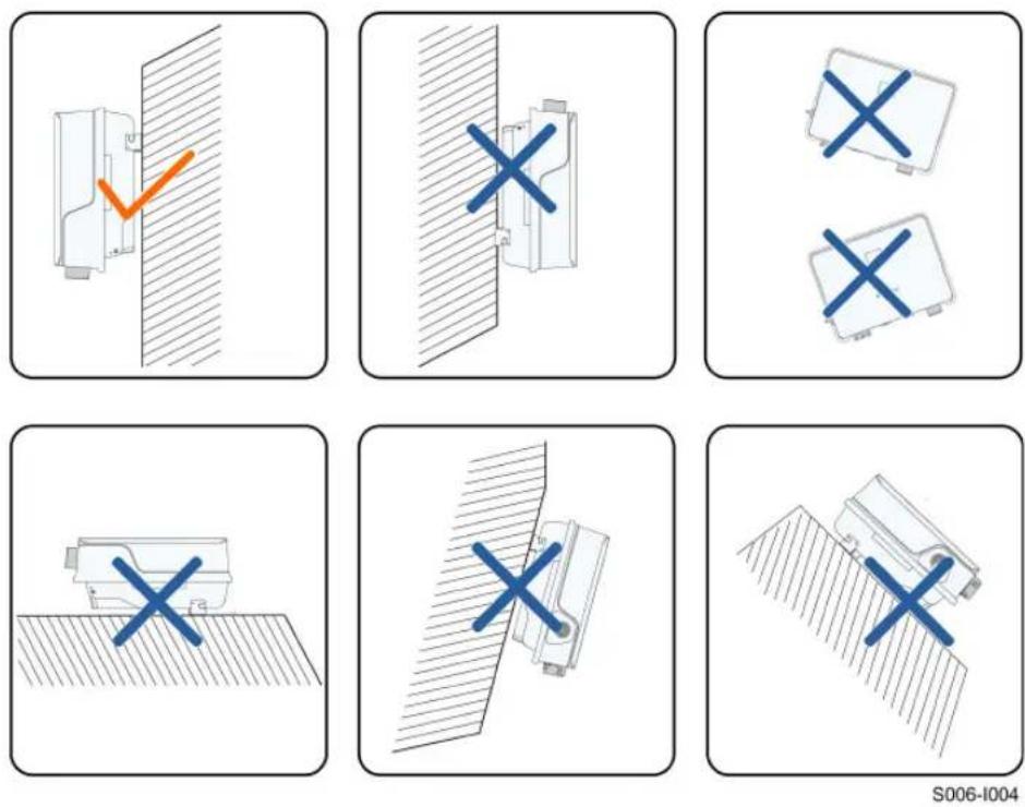
Install the inverter vertically. Never install the inverter horizontally, or at forward/backward tilted, side tilted, or upside down.
4.2.4 Clearance Requirements
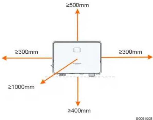
Reserve enough clearance around the inverter to ensure sufficient space for heat dissipation.
Install the inverter at an appropriate height for ease of viewing the screen and LED indicator and operating switch(es).
4.3 Installation Tools
Installation tools include but are not limited to the following recommended ones. If necessary, use other auxiliary tools on site.
table 4-1 Tool specification
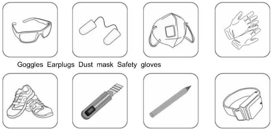
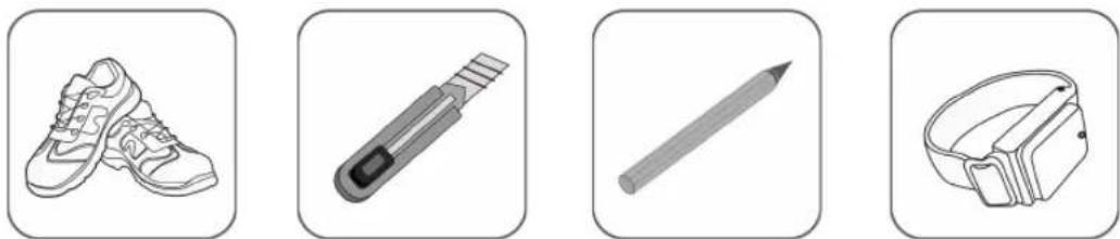
Safety shoes Utility knife Marker Anti-static wrist
strap
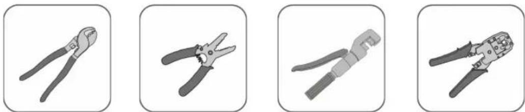
Wire cutter Wire stripper Hydraulic pliers RJ45 crimping tool
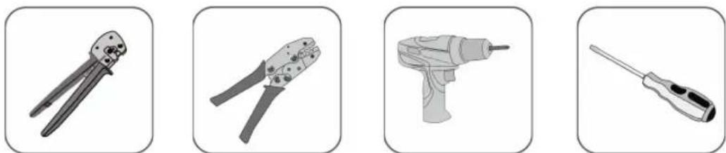
OT terminal crimp-
ing tool (4 mm ^2 6
mm ^2 )
MC4 terminal crimping tool (0.5 mm²–1.0 mm²)
Electric screwdriver (M4, M5, M6)
Slotted screwdriver (M2)
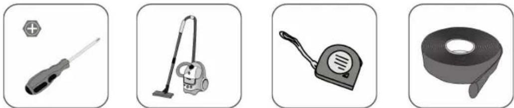
Phillips screwdriver (M4)
Vacuum cleaner Measuring tape Heat shrink tubing
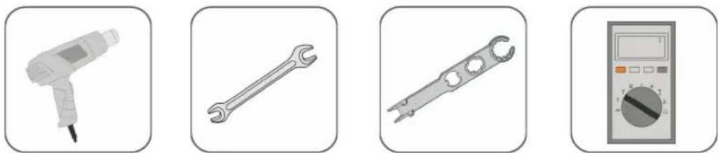
Heat gun Open-end wrench
(33 mm, 35 mm)
Connector wrench Multimeter ( ≥ 600
Vdc)

natural_image
Simple illustration of a hammer (no text or symbols)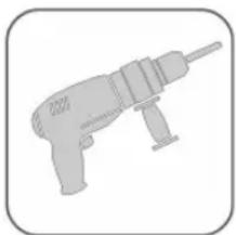
natural_image
Silhouette of a drill bit with no text or symbols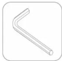
natural_image
Simple line drawing of a bent pipe or handle (no text or symbols)Rubber mallet Hammer drill ( 10) Allen wrench (T27)
4.4 Moving the Inverter
Before installation, remove the inverter from the packing case and move it to the installation site. Follow the instructions below as you move the inverter:
• Always be aware of the weight of the inverter.
- Lift the inverter using the handles positioned on both sides of the inverter.
- Move the inverter by one or two people or by using a proper transport tool.
- Do not release the equipment unless it has been firmly secured.
CAUTION
Improper handling may cause personal injury!
- Arrange an appropriate number of personnel to carry the inverter according to its weight, and installation personnel should wear protective equipment such as anti-impact shoes and gloves.
- Attention must be paid to the center of gravity of the inverter to avoid tilting during handling.
- Placing the inverter directly on a hard ground may cause damage to its metal enclosure. Protective materials such as sponge pad or foam cushion should be placed underneath the inverter.
- Move the inverter by holding the handles on it. Do not move the inverter by holding the terminals.
4.5 Installing the Inverter
Inverter is installed on the wall by means of wall-mounting bracket and the expansion plug sets.
The expansion plug set shown below is recommended for the installation.
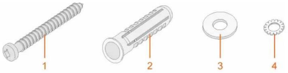
(1) Self-tapping screw M6
(2) Expansion tube (3) Fender washer (4) Spring washer
Step 1 Place the wall-mounting bracket to a proper position on the wall. Mark the positions and drill the holes.
NOTICE
Observe the level on the bracket and adjust until the bubble is in the middle position.
The depth of the holes should be about 70 mm.
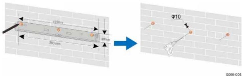
* The image shown here is for reference only. The actual product received may differ.
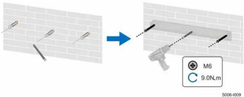
Step 2 Place the expansion tubes into the holes. Then secure the wall-mounting bracket to the wall firmly with the expansion bolt sets.
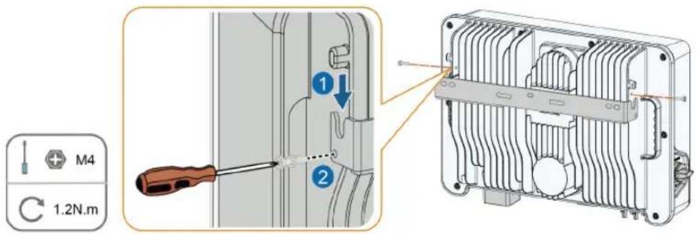
Step 3 Lift the inverter and slide it down along the wall-mounting bracket to make sure they match perfectly. Use two screw sets to lock both left and right sides.
S005-1010
-- End
5 Electrical Connection
5.1 Safety Instructions
! DANGER
The PV string will generate lethal high voltage when exposed to sunlight.
- Operators must wear proper personal protective equipment during electrical connections.
- Must ensure that cables are voltage-free with a measuring instrument before touching DC cables.
- Respect all safety instructions listed in relevant documents about PV strings.
! DANGER
- Before electrical connections, please make sure that the inverter switch and all switches connected to the inverter are set to "OFF", otherwise electric shock may occur!
- Ensure that the inverter is undamaged and all cables are voltage free before performing electrical work.
- Do not close the AC circuit breaker until the electrical connection is completed.
! WARNING
Do not damage the ground conductor. Do not operate the product in the absence of a properly installed ground conductor. Otherwise, it may cause personal injury or product damage.
Please use measuring devices with an appropriate range. Overvoltage can damage the measuring device and cause personal injury.
Damage to the product caused by incorrect wiring is not covered by the warranty.
- Electrical connection must be performed by professionals.
- Operators must wear proper personal protective equipment during electrical connections.
- All cables used in the PV generation system must be firmly attached, properly insulated, and adequately dimensioned. Cables used shall comply with the requirements of local laws and regulations.
- The factors that affect cable selection include rated current, cable type, routing mode, ambient temperature, and maximum expected line loss.
NOTICE
All electrical connections must comply with local and national/regional electrical standards.
- Cables used by the user shall comply with the requirements of local laws and regulations.
- Only with the permission of the national/regional grid department, the inverter can be connected to the grid.
- Requires external protection device.
- Requires external multipole interruption device for current carrying wires disconnection.
- Requires an external residual current device (DR), suitable for protection against electric shock, in accordance with the ABNT NBR 5410 standard.
- It is expressly recommended to use rapid shutdown methods, systems or devices on the d.c.circuit. that guarantee safety in firefighting situations.
- The installation of this equipment must comply with current technical standards for photovoltaic electrical installation (NBR 16690) and fire risk management in photovoltaic systems (IEC 63226).
- This equipment is compatible with external independent rapid shutdown devices.
NOTICE
• Install the external protective grounding cable first when performing electrical connection and remove the external protective grounding cable last when removing the inverter.
- Keep the AC output cable and the DC input cable close to each other during electrical connection.
- Comply with the safety instructions related to PV strings and the regulations related to the utility grid.
NOTICE
- After being crimped, the OT terminal must wrap the wires completely, and the wires must contact the OT terminal closely.
- When using a heat gun, protect the device from being scorched.
- Keep the PV+ cable and PV− cable close to each other when connecting DC input cables.
- Before connecting a power cable (such as the AC cable, the DC cable, etc.), confirm that the label and identifier on the power cable are correct.
- When laying out communication cables, separate them from power cables and keep them away from strong interference sources to prevent communication interruption.
- All vacant terminals must be covered with waterproof covers to prevent affecting the protection performance.
- Ensure that AC output cables are firmly connected. Failing to do so may cause inverter malfunction or damage to its AC connectors.
- When the wiring is completed, seal the gap at the cable inlet and outlet holes with fireproof/waterproof materials such as fireproof mud to prevent foreign matter or moisture from entering and affecting the long-term normal operation of the inverter.

The cable colors in figures in this manual are for reference only. Please select cables according to local cable standards.
5.2 Terminal Description
All electrical terminals are located at the bottom side of the inverter.
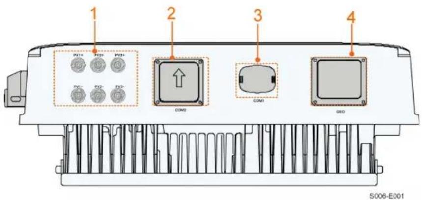
figure 5-1 Terminals
* The image shown here is for reference only. The actual product received may differ. table 5-1 Terminal Description
| No. | Name | Description | Decisive Voltage Classification |
| 1 | PV1+, PV1−, PV2+, PV2−, PV3+, PV3− | The terminal number depends on inverter model. | DVC-C |
| 2 | COM2 / / | ||
| 3 | COM1 | Communication accessory port to be connected to WiFi-P2 communication module. | DVC-A |
| 4 | GRID | AC terminal to connect to the grid. | DVC-C |
5.3 Electrical Connection Overview
The electrical connection should be realized as follows:
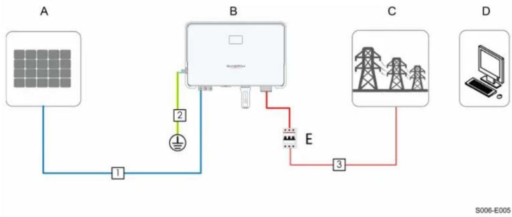
flowchart
graph TD
    A["Solar Panel"] -->|1| B["Battery"]
    B -->|2| C["Transmission Line"]
    C -->|3| D["Power Grid"]
    D --> E["Computer"]
(A) PV string (B) Inverter (C) Grid
(D) External device (E) AC circuit breaker
table 5-2 Cable Requirements
| No. | Cable | Type | Cable Diameter | Cross-section |
| 1 | DC cable | Outdoor multi-core copper wire cable complying with 600 V and 20 A standard | 4.7 mm ~ 6.4 mm | 4 mm^2 ~ 6 mm^2 |
| 2 | External Grounding cable | Outdoor single-core copper wire cable | 4 mm ~ 10 mm | 6 mm^2 ~ 10 mm^2 |
| 3 | AC cable(1)(2) | Outdoor one 3-core copper wire cable | SG7.5/8.0RS-L: 16 mm ~ 22 mmSG9.0/10RS-L: 18 mm ~ 25.8 mm | SG7.5/8.0RS-L: 8 mm^2 ~ 10 mm^2 SG9.0/10RS-L: 10 mm^2 ~ 16 mm^2 |
| Outdoor three single-core copper wire cables | SG7.5/8.0RS-L: 6.3 mm ~ 7.5 mmSG9.0/10RS-L: 7.5 mm ~ 9.4 mm | SG7.5/8.0RS-L: 8 mm^2 ~ 10 mm^2 SG9.0/10RS-L: 10 mm^2 ~ 16 mm^2 |
(1) All the AC wires should be equipped with correctly colored cables for distinguishing. Please refer to related standards about the wiring color.
(2) Select appropriate OT terminals based on the diameter of the AC cable.

It is recommended to use heavy duty conduits when run cables through Cavity walls, or lay out cables with corresponding conduits. (For "AU" and "NZ")
5.4 External Protective Grounding Connection
! DANGER
- There are large currents during the inverter's operation. If the inverter is powered on and put into operation without being grounded, it may lead to electric shock hazards or failures of major protective functions such as surge protection. Therefore, before powering on the inverter, make sure it has been reliably grounded; otherwise, damages caused therefrom will not be covered by warranty.
- When performing electrical connections of the inverter, give the highest priority to grounding. Be sure to carry out the grounding connection first.
WARNING
- Since the inverter is not equipped with a transformer, neither the negative electrode nor the positive electrode of the PV string can be grounded. Otherwise, the inverter will not operate normally.
- Connect the grounding terminal to the external protective grounding point before AC cable connection, PV string connection, and communication cable connection.
- The external protective grounding point provides a reliable ground connection. Do not use an improper grounding conductor for grounding, Otherwise, it may cause product damage or personal injury.
- Depending on Local Rules, please also ground the PV panel subconstruction to the same common grounding point (PE Bar) in addition to local lightning protection rules.
WARNING
The external protective grounding terminal must meet at least one of the following requirements.
- The cross-sectional area of the grounding cable is not less than ^2 for copper wire or 16 m for aluminum wire. It is recommended that both the external protective grounding terminal and the AC side grounding terminal be reliably grounded.
- If the cross-sectional area of the grounding cable is less than ^2 for copper wire or 16 mm ^2 for aluminum wire, ensure that both the external protective grounding terminal and the AC side grounding terminal are reliably grounded.
The grounding connection can be made by other means if they are in accordance with the local standards and regulations, and SUNGROW shall not be held liable for the possible consequences.
5.4.1 External Protective Grounding Requirements
All non-current carrying metal parts and device enclosures in the PV power system should be grounded, for example, brackets of PV modules and inverter enclosure.
When there is only one inverter in the PV system, connect the external protective grounding cable to a nearby grounding point.
When there are multiple inverters in the PV system, connect the external protective grounding terminals of all inverters and the grounding points of the PV module brackets to ensure equipotential connections to ground cables (according to the onsite conditions).
5.4.2 Connection Procedure
External grounding cable and OT/DT terminal are prepared by customers.
Step 1 Prepare the cable and OT/DT terminal.
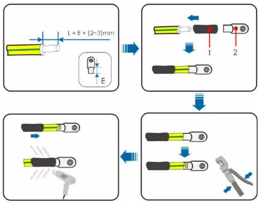
(1) Heat shrink tubing (2) OT/DT terminal

After being crimped, the OT terminal must wrap the wires completely, and the wires must contact the OT terminal closely.
When using a heat gun, protect the device from being scorched.
Step 2 Remove the screw on the grounding terminal and fasten the cable with a screwdriver.
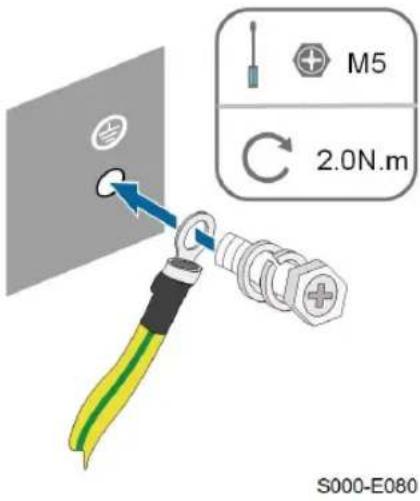
Step 3 Apply paint to the grounding terminal to ensure corrosion resistance.
-- End
5.5 AC Cable Connection
5.5.1 AC Side Requirements

Only with the permission of the local grid department, the inverter can be connected to the grid.
Before connecting the inverter to the grid, ensure the grid voltage and frequency comply with requirements, for which, refer to "Technical Date". Otherwise, contact the electric power company for help.
AC Circuit Breaker
An independent two-pole circuit breaker must be installed on the output side of the inverter to ensure safe disconnection from the grid. The recommended specifications are as follows.
| Inverter Model | Recommended Specification |
| SG7.5RS-L/SG8.0RS-L/SG9.0RS-L 50A | |
| SG10RS-L 63 A |
NOTICE
Testing to AS/NNZS 4777.2:2020 Section for multiple phase combinations has not been conducted.
! WARNING
AC circuit breakers should be installed on the output side of the inverter and the grid side to ensure safe disconnection from the grid.
- Determine whether an AC circuit breaker with greater overcurrent capacity is required based on actual conditions.
- Do not connect any local load between the inverter and the AC circuit breaker.
- Multiple inverters cannot share one AC circuit breaker.
Residual Current Monitoring Device
With an integrated universal current-sensitive residual current monitoring unit included, the inverter will disconnect immediately from the mains power once a fault current with a value exceeding the limit is detected.
However if an external residual current device (RCD) (type A is recommended) is mandatory, the switch must be triggered at a residual current of 300 mA (recommended). RCD of other specifications can also be used according to local standard.
In Australia, a RCD is not required according to the local standard AS3000-2018 when either of the following installation methods is adopted if the PV array capacitance to ground is large (such as a tin roof):
- Use heavy duty conduits (such as metal bushing) when run PV and AC cables through Cavity walls.
- Route the PV and AC cables through pipes (PVC or metal tubing), lay the cables and install them.
5.5.2 Connecting the AC Cable
Step 1 Disconnect the AC circuit breaker and secure it against reconnection.
Step 2 Take out the AC waterproof cover, unscrew the swivel nut and take out the sealing ring. Thread the AC cable through the swivel nut, appropriate sealing and waterproof cover in sequence.
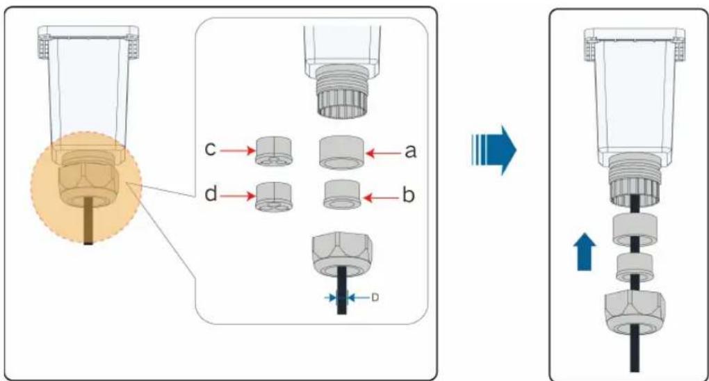
| Cable diameter D ( mm ) Sealing rings | Remarks | |
| 16~18 a+b One three-core cable | ||
| 18~25.8 | a | One three-core cable |
| 6.3~7.5(*3) | a+c | 8AWG, 7AWG, three single-core cables |
| 8.5~9.4(*3) | a+d | 6AWG, 5AWG, three single-core cables |
Step 3 Strip the cable jacket and the wire insulation as shown in the following figure.
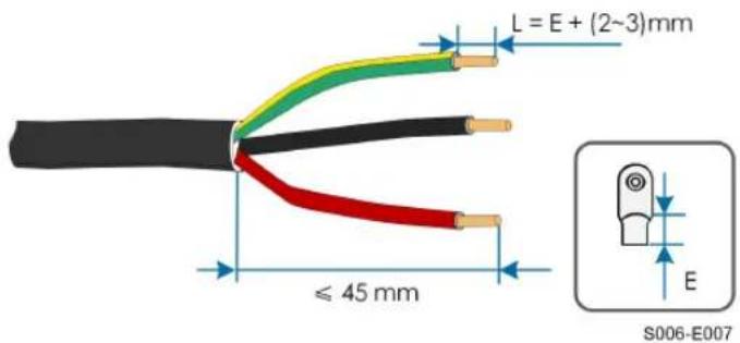
Step 4 Crimp the OT/DT terminal.
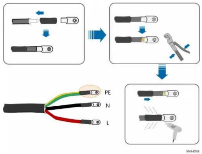
flowchart
graph TD
    A["Pinning with two leads"] --> B["Disassembly"]
    B --> C["Cutting into a wire"]
    C --> D["Disassembly with a tool"]
    D --> E["Final disassembly with a probe and wire"]
    E --> F["Final disassembly with a probe and wire"]
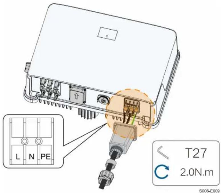
Step 5 Fix all the wires to the terminals according to the assignment and tighten to a torque of 2.0 N·m with a screwdriver.
NOTICE
Observe the terminal assignment. Do not connect any phase line to the "PE" terminal or PE wire to "N" terminal. Otherwise, unrecoverable damage to the inverter may follow.
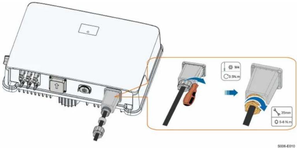
Step 6 Secure the AC waterproof cover to the inverter with a torque of 1.0 N·m and tighten the swivel nut to a torque of 5 N·m–6 N·m.
Step 7 Connect the PE wire to ground and the phase lines and the "N" line to AC circuit breaker. Then connect the AC circuit breaker to electric board.
Step 8 Make sure all wires are firmly installed via the right torque tool or dragging the cables slightly.
-- End
5.6 DC Cable Connection
! DANGER
The PV string will generate lethal high voltage when exposed to sunlight.
- Respect all safety instructions listed in relevant documents about PV strings.
! WARNING
- Make sure the PV array is well insulated to ground before connecting it to the inverter.
- Make sure the maximum DC voltage and the maximum short circuit current of any string never exceed inverter permitted values specified in "Technical Data".
- Check the positive and negative polarity of the PV strings, and connect the PV connectors to corresponding terminals only after ensuring polarity correctness.
- During the installation and operation of the inverter, please ensure that the positive or negative electrodes of PV strings do not short-circuit to the ground. Otherwise, an AC or DC short-circuit may occur, resulting in equipment damage. The damage caused by this is not covered by the warranty.
- Electric arc or contactor over-temperature may occur if the DC connectors are not firmly in place, and the loss caused is not covered by the warranty.
- If the DC input cables are reversely connected or the positive and negative terminals of different MPPT are shorted to ground at the same time, while the DC switch is in the "ON" position, do not operate immediately. Otherwise, the inverter may be damaged. Please turn the DC switch to "OFF" and remove the DC connector to adjust the polarity of the strings when the string current is lower than 0.5 A.
- Use the DC connectors supplied with the product for DC cable connection. Using incompatible DC connectors may result in serious consequences, and the device damage is not covered under warranty.
- Inverters do not support full parallel connection of strings (Full parallel connection refers to a connection method in that strings are connected in parallel and then connected to the inverter separately).
- Do not connect one PV string to multiple inverters. Otherwise, the inverters may be damaged.
NOTICE
The following requirements about PV string connection must be met. Otherwise, it may cause irreversible damage to the inverter, which is not covered by the warranty.
- Mixed use of PV modules of different brands or models in one MPPT circuit, or PV modules of different orientation or inclination in a string may not damage inverter, but will cause system bad performance!
- The inverter enters standby state when the input voltage ranges between 560 V and 600 V. The inverter returns to running state once the voltage returns to the MPPT operating voltage range, namely, 40 V to 560 V.
NOTICE
Note the following items when laying cables on site:
- The axial tension on PV connectors must not exceed 80 N. Avoid axial cable stress on the connector for a long time during field wiring.
- Radial stress or torque must not be generated on PV connectors. It may cause the connector waterproof failure and reduce connector reliability.
- Leave at least 50 mm of slack to avoid the external force generated by the cable bending affecting the waterproof performance.
- Refer to the specifications provided by the cable manufacturer for the minimum cable bending radius. If the required bending radius is less than 50 mm, reserve a bending radius of 50 mm. If the required bending radius is greater than 50 mm, reserve the required minimum bending radius during wiring.
5.6.1 PV Input Configuration
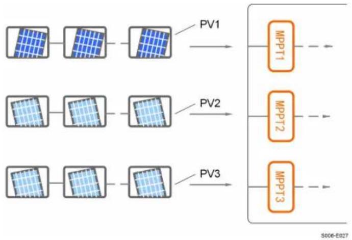
- The inverters SG7.5RS-L/SG8.0RS-L/SG9.0RS-L/SG10RS-L have three PV inputs.
- SG7.5RS-L/SG8.0RS-L has 2 DC input areas and SG9.0/10RS-L has 3 DC input areas, with each area equipped with an independent MPPT and able to operate independently. For SG7.5RS-L/SG8.0RS-L inverters, PV1 and PV2 can share one MPPT in Parallel Connection mode.
- The PV strings to the same DC input area should have the same type, the same number of PV panels, identical tilt and identical orientation for maximum power.
- The PV strings to two DC input areas may differ from each other, including PV module type, number of PV modules in each string, angle of tilt, and installation orientation.
- Three modes are available for PV input connection, namely, Independent mode, Parallel Connection mode, and Partial Parallel Connection mode. In Partial Parallel Connection mode, the parallel connection of PV1 and PV2 is supported.
flowchart
graph LR
    A["Grid Array 1"] --> B["Grid Array 2"]
    B --> C["Grid Array 3"]
    C --> D["MPPT1"]
    C --> E["MPPT2"]
    C --> F["MPPT3"]
    style A fill:#f9f,stroke:#333
    style B fill:#f9f,stroke:#333
    style C fill:#f9f,stroke:#333
    style D fill:#ccf,stroke:#333
    style E fill:#ccf,stroke:#333
    style F fill:#ccf,stroke:#333
figure 5-2 PV Input Configuration(SG9.0/10RS-L for example)
Prior to connecting the inverter to PV inputs, the specifications in the following table should be met:
Inverter Model Open-circuit Voltage Limit Max. current for input connector
All models
600 V 20 A
5.6.2 Assembling the PV Connectors
! DANGER
High voltage may be present in the inverter!
- Ensure all cables are voltage-free before performing electrical operations.
- Do not connect the DC switch and AC circuit breaker before finishing electrical connection.

To ensure IP65 protection, use only the supplied connector.
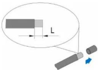
Step 1 Strip the insulation from each DC cable by 7 mm–8 mm.
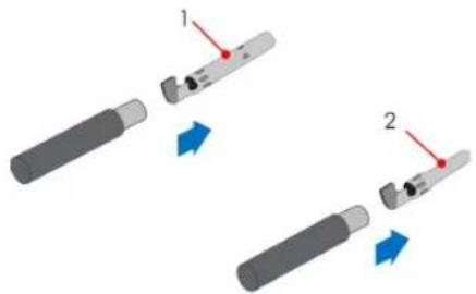
Step 2 Assemble the cable ends with the crimping pliers.
natural_image
Two mechanical tools with red arrows indicating movement or assembly (no text or symbols)1: Positive crimp contact 2: Negative crimp contact
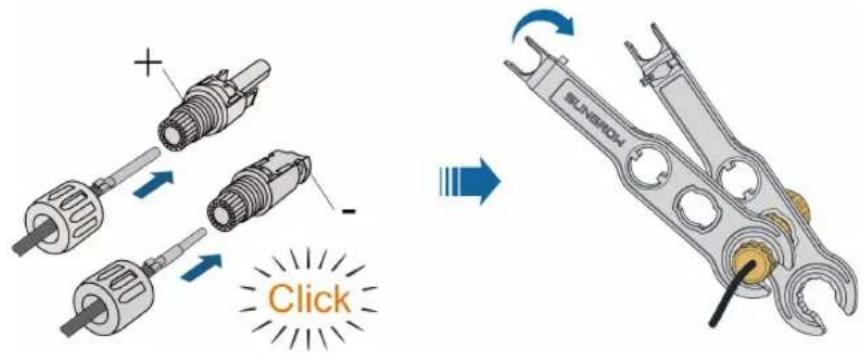
Step 3 Lead the cable through cable gland, and insert the crimp contact into the insulator until it snaps into place. Gently pull the cable backward to ensure firm connection. Tighten the cable gland and the insulator (torque 2.5 N.m to 3 N.m).
Step 4 Check for polarity correctness.
NOTICE
If the PV polarity is reversed, the inverter will be in a fault or alarm state and will not operate normally.
-- End
5.6.3 Installing the PV Connectors
Step 1 Rotate the DC switch to "OFF" position.
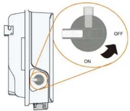
S006-E032
Step 2 Check the cable connection of the PV string for polarity correctness and ensure that the open circuit voltage in any case does not exceed the inverter input limit of 600 V.
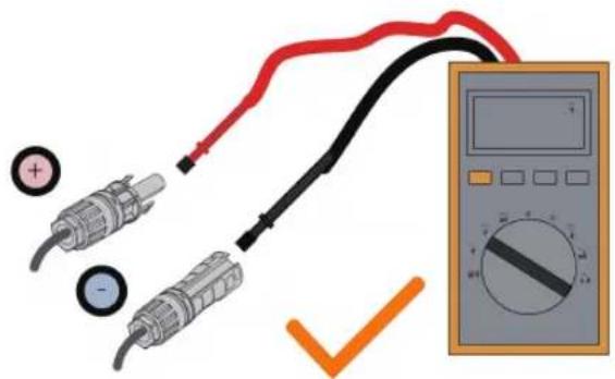
Step 3 Connect the PV connectors to corresponding terminals until there is an audible click.
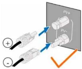
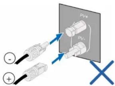
Step 4 Seal the unused PV terminals with the terminal caps.
-- End
5.7 Communication Connection
5.7.1 WLAN Communication
Step 1 Remove the waterproof lid from the COM1 terminal.
Step 2 Install the module. Slightly shake it by hand to determine whether it is installed firmly, as shown below.
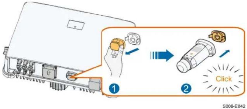
Step 3 Refer to the guide delivered with the module for the set-up.
-- End
6 Commissioning
6.1 Inspection Before Commissioning
Check the following items before starting the inverter:
- All equipment has been reliably installed.
- DC switch(es) and AC circuit breaker are in the "OFF" position.
- The ground cable is properly and reliably connected.
- The AC cable is properly and reliably connected.
- The DC cable is properly and reliably connected.
- The communication cable is properly and reliably connected.
- The unused terminals are sealed.
- No foreign items, such as tools, are left on the top of the machine or in the junction box (if there is).
- The AC circuit breaker is selected in accordance with the requirements of this manual and local standards.
- All warning signs & labels are intact and legible.
6.2 Powering on the System
If all of the items mentioned above meet the requirements, proceed as follows to start up the inverter for the first time.
Strictly follow the preceding sequence. Otherwise, the product may be damaged, and the loss caused is not covered by the warranty.
Step 1 Turn on the AC circuit breaker between the inverter and the grid.

Before closing the AC circuit breaker between the inverter and the power grid, use a multimeter that is set to the AC gear to ensure that the AC voltage is within the specified range. Otherwise, the inverter may be damaged.
Step 2 Rotate the DC switch of the inverter to "ON" position.
Step 3 Turn on the external DC switch (if applicable) between the inverter and the PV string.
Step 4 If the irradiation and grid conditions meet requirements, the inverter will operate normally. Observe the LED indicator to ensure that the inverter operates normally. Refer to "2.4 LED Panel" for LED screen introduction and LED indicator definition.
Step 5 Refer to the quick guide for WiFi-P2 for its indicator definition.
-- End
6.3 App Preparation
Step 1 Install the iSolarCloud App with latest version. Refer to "7.2 Installing App".
Step 2 Register an account. Refer to "7.3 Account Registration". If you have got the account and password from the distributor/installer or SUNGROW, skip this step.
Step 3 Download the firmware package to the mobile device in advance. Refer to "Firmware Upa-date". This is to avoid download failure due to poor on-site network signal.
-- End
6.4 Creating a Plant
Prerequisites:
- The account and password for logging in to iSolarCloud App have been obtained from the distributor/installer or SUNGROW.
- The communication device is normally connected to the inverter.
- System positioning is enabled and iSolarCloud App is allowed to access location information.
Instructions are given with a WiFi-P2 communication module used as an example.
More
Step 1 Open the App, tap in the upper right corner of the interface, and select the correct access address.
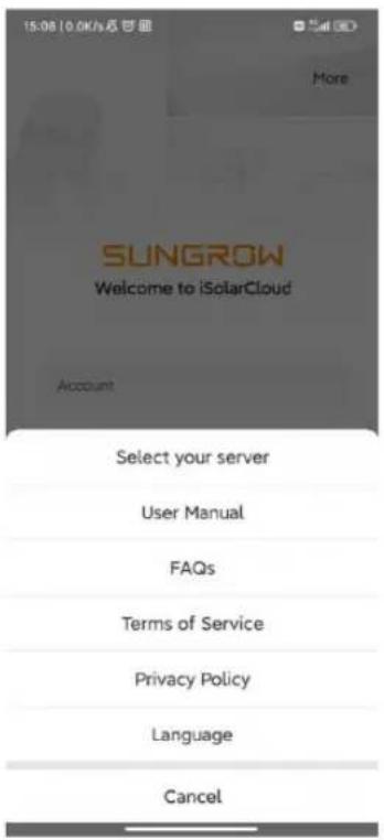
figure 6-1 Select Access Address
Step 2 Enter the account and password on the login interface, and tap LOGIN to log in.
Step 3 Tap ^+ in the upper right corner to enter the plant creation interface.
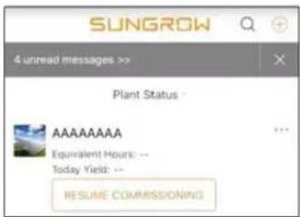
Step 4 Fill in the content according to actual needs, and the parameters containing * are required. Tap Next to enter the next interface.
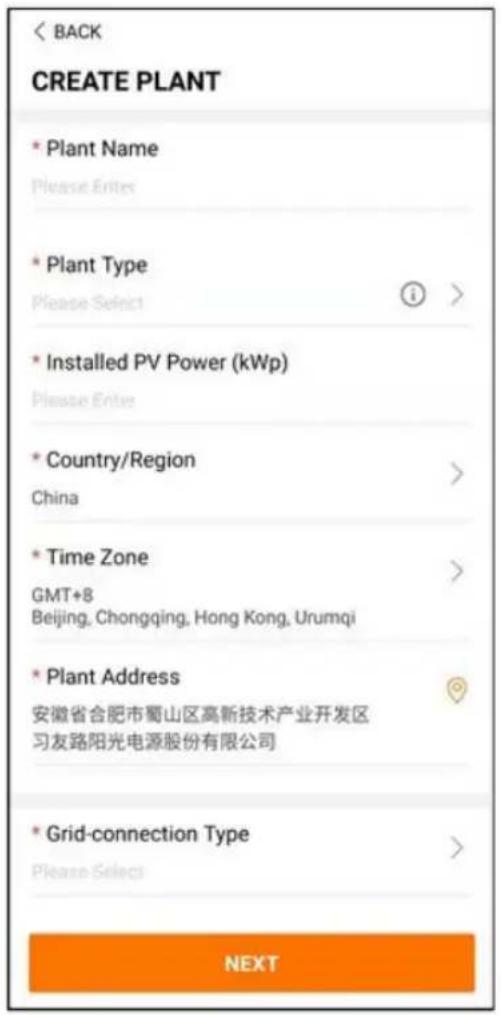
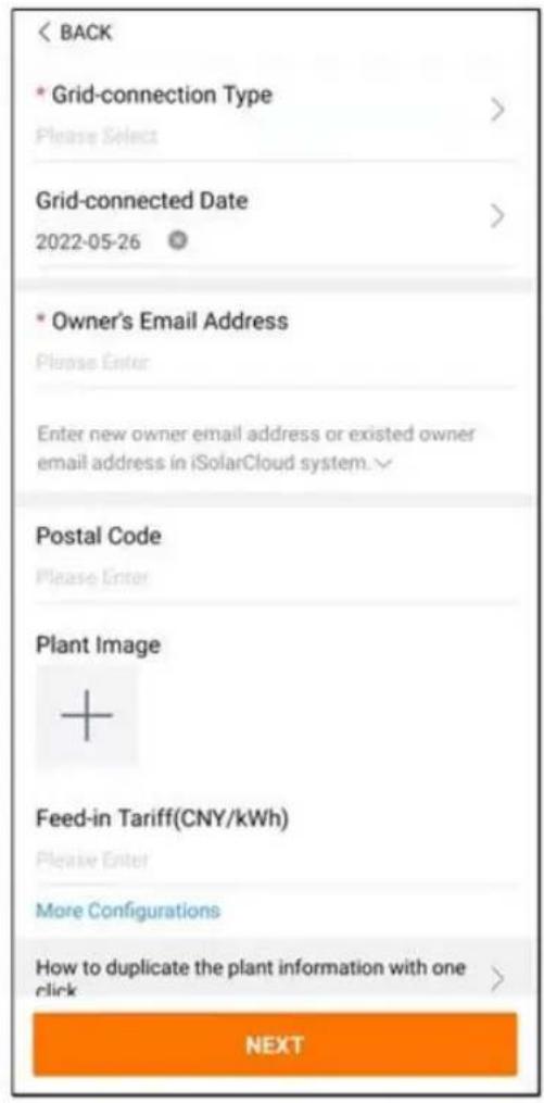
figure 6-2 Plant Creation Settings
| Parameter Name | Description |
| Plant name | The name of the plant. |
| Plant type | The type of the plant, which should be set corresponding to the actual plant type. |
| Installed power | The installed power of the plant. |
| Country/Region | The country/region where the plant is located. |
| Time zone | The time zone where the plant is located, which can be filled through automatic positioning and manual input. |
| Plant address | The location of the plant, which can be filled in two ways:Manually: Manually enter the plant location in the input box.Automatically: Tap to automatically obtain the current location or search for the location of the plant, and then tap Confirm. |
| Grid-connection type | The way the plant is connected to the grid, including 100% Feed-in, Self-Consumption, Zero Export, and Off-grid. |
| Grid-connected date | The time when the plant is connected to the grid. |
| Owner's email address | Fill in the owner information of the plant, and both registered and un-registered email addresses are supported. |
| Postal code The | postal code of the place where the plant is located. |
| Plant image Take photos of the plant and upload them. | |
| Feed-in tariff | The feed-in tariff can be set in two ways:Enter the feed-in tariff directly in the input box.Tap More Configurations, select the tariff unit, enter the feed-in tariff, and tap Confirm. Enable Time-of-Use Tariff if needed. Tap Add Time-of-Use Tariff, add time intervals and price, and tap Confirm. Please note that if Time-of-use Tariff is enabled, the time periods shall cover 24 hours a day, and can not overlap. |
| Consumption tariff | Set the consumption tariff as follows:Tap More Configurations, select the tariff unit, enter the consumption tariff, and tap Confirm. Enable Time-of-Use Tariff if needed, and refer to the setting methods of the feed-in tariff. |
Step 5 Bind a device through scanning the QR code on the device, manually inputting the device S/
N, or uploading a QR code picture. Tap Confirm after the QR code is identified or the S/N is verified.
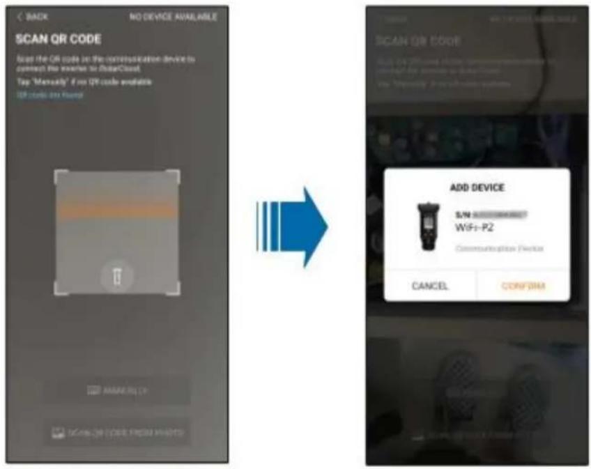
Step 6 After a device is bound, tap Device and Commissioning to go to corresponding interface.
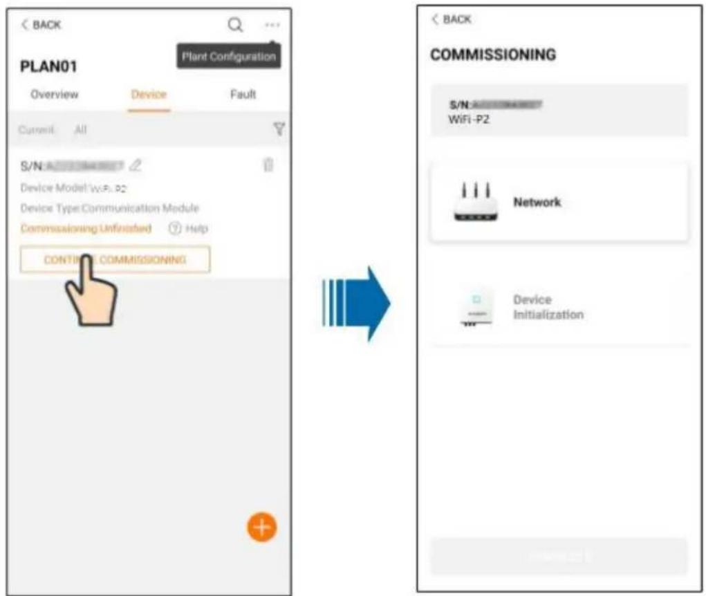
Step 7 Tap Network Configuration to go to the WLAN connection interface. Tap the home network in the WLAN list, enter the password, and then tap Confirm.
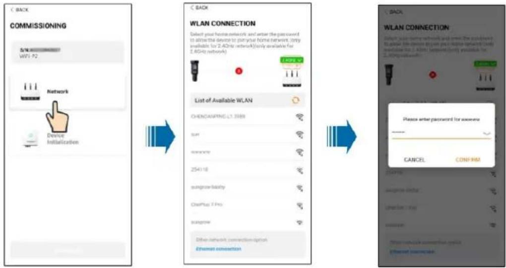
Step 8 Enter the Activate EasyConnect interface, and press the multi-function button on the WiFi —P2 to enable the Easyconnect mode according to the prompt on the screen. The App automatically enters a waiting processing interface if this mode is enabled, and automatically returns to the commissioning interface after the processing is completed.
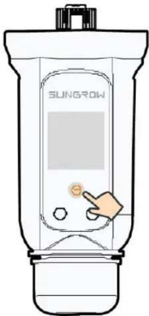
NOTICE
Only the 2.4 GHz working band is supported under the networking mode. If the Easyconnect fails, please refer to other methods in the WiFi—P2 manual to establish the connection.
Step 9 Tap Device Initialization to go to the Device initialization interface. Set the initialization protection parameters as needed and tap Settings to return to the commissioning interface.
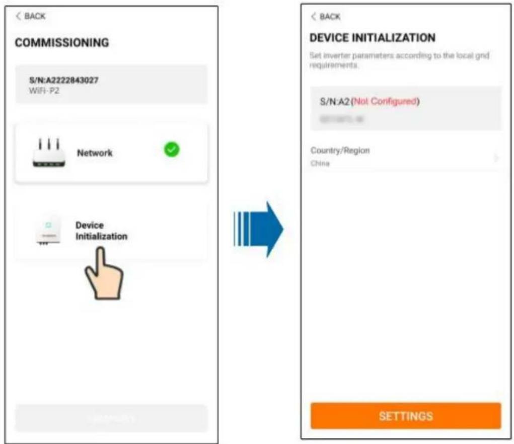
When the country is set to Australia, additionally set the applicable network service provider and then the grid type.
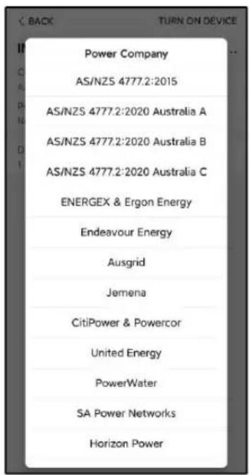
The image shown here is for reference only. Refer to the actual interface for the supported network service providers.
table 6-1 Description of Network Service Provider and Grid Type
| Network Service Provider Grid Type | |
| AS/NZS 4777.2:2015 / | |
| AS/NZS 4777.2:2020Australia A | / |
| AS/NZS 4777.2:2020Australia B | / |
| AS/NZS 4777.2:2020Australia C | / |
| ENERGEX & Ergon Energy | • STNW1170: single-phase < 10 kVA & three-phase < 30 kVA• STNW1174: 30 kVA < P≤ 1500 kVA |
| Jemena | • ≤ 10 kVA per phase (or 30 kVA per three phase)• ELE GU 0014: 30 kVA–200 kVA |
| Endeavour Energy | MDI 0043 |
| Ausgrid | NS194 |
| CitiPower & Powercor | • ≤ 5 kVA for single-phase & 30 kVA for three-phase• > 30 kVA three-phase |
| United Energy | • UE-ST-2008.1: ≤ 10 kVA for single-phase & 30 kVA for three-phase• UE-ST-2008.2: > 30 kVA three-phase |
| PowerWater | Embedded Generation Notice Photovoltaic Systems:2020 |
| SA Power Networks | • TS129-2019: < 10 kW for single-phase & 30 kW for three-phase• TS130-2017: > 30 kW & ≤ 200 kW• TS131-2018: > 200 kW |
| Horizon Power | • HPC-9DJ-13-0001-2019: ≤ 10kVA for single-phase & 30 kVA for three-phase• HPC-9DJ-13-0002-2019: > 30kVA & ≤1MVA |
| westernpower | EDM#33612889-2019 |
| AusNet Services | Basic Micro Embedded Generation: 2020 |
* For compliance with AS/NZS 4777.2:2020, please select from Australia A/B/C. Please contact your electricity grid operator for which region to use.
i
- Please check the country supported by this product at http://support.sungrow-power.com/.
- Set Country/Region to the country/region where the inverter is installed. Otherwise, the inverter may report a fault.
Step 10 After a plant is successfully created, return to the App home page to view the plant information.
-- End
6.5 Initializing the Device
The inverter is successfully connected to the router.
If there is no latest equipment upgrade package, skip steps 1 and 2.
The actual initializing procedure may differ due to different countries. Please follow the actual App guidance.
Step 1 If a latest equipment upgrade package is available, the following prompt window pops up. Tap UPDATE NOW to download the latest update package.
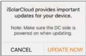
figure 6-3 Upgrade Reminder
Step 2 After download, it would take around 15 minutes to update. After successful upgrade, the screen will show the version numbers before and after the upgrade as well as the upgrade time. Tap NEXT.
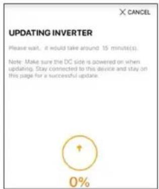
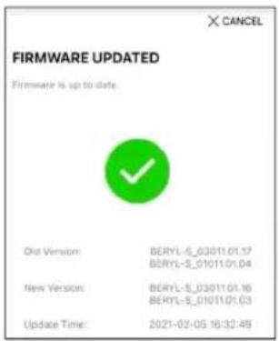
figure 6-4 Upgrading Inverter
NOTICE
If the communication equipment is upgraded, after successful upgrade, check and confirm that the phone is connected to the inverter WLAN.
Step 3 Tap Country/Region and select the country where the inverter is installed at. The supported countries and corresponding settings are as follows.
Country/Region Setting
Australia ("AU") Australia
New Zealand ("NZ") New Zealand
Chile Chile
Brazil ("BR") Brazil
NOTICE
The parameter Country/Region must be set to the country (region) where the inverter is installed at. Otherwise, the inverter may report errors.
Step 4 When the country is set to Australia, additionally set the applicable network service provider and then the grid type.
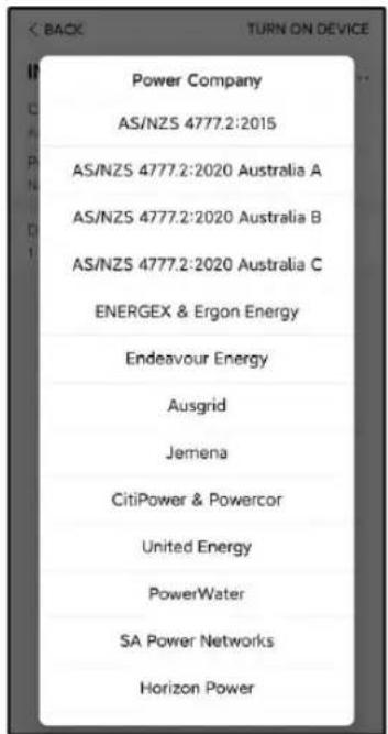
The image shown here is for reference only. Refer to the actual interface for the supported network service providers.
table 6-2 Description of Network Service Provider and Grid Type
| Network Service Provider Grid Type | |
| AS/NZS 4777.2:2015 / | |
| AS/NZS 4777.2:2020 | / |
| Australia A | |
| AS/NZS 4777.2:2020 | / |
| Australia B | |
| AS/NZS 4777.2:2020 | / |
| Australia C | |
| ENERGEX & Ergon Energy | • STNW1170: single-phase < 10 kVA & three-phase < 30 kVA• STNW1174: 30 kVA < P≤ 1500 kVA |
| Jemena | • ≤ 10 kVA per phase (or 30 kVA per three phase)• ELE GU 0014: 30 kVA–200 kVA |
| Endeavour Energy | MDI 0043 |
| Ausgrid | NS194 |
| CitiPower & Powercor | • ≤ 5 kVA for single-phase & 30 kVA for three-phase• > 30 kVA three-phase |
| United Energy | • UE-ST-2008.1: ≤ 10 kVA for single-phase & 30 kVA for three-phase• UE-ST-2008.2: > 30 kVA three-phase |
| PowerWater | Embedded Generation Notice Photovoltaic Systems:2020 |
| SA Power Networks | • TS129-2019: < 10 kW for single-phase & 30 kW for three-phase• TS130-2017: > 30 kW & ≤ 200 kW• TS131-2018: > 200 kW |
| Horizon Power | • HPC-9DJ-13-0001-2019: ≤ 10kVA for single-phase & 30 kVA for three-phase• HPC-9DJ-13-0002-2019: > 30kVA & ≤1MVA |
| westernpower | EDM # 33612889-2019 |
| AusNet Services Basic Micro Embedded Generation: 2020 | |
* For compliance with AS/NZS 4777.2:2020, please select from Australia A/B/C. Please contact your electricity grid operator for which region to use.
Step 5 Initialize parameters according to local grid requirements, including grid type, reactive power regulation mode, etc. The screen displays that the inverter is successfully configured.
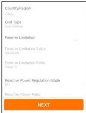
figure 6-5 Initializing Parameters
-- End
6.6 Configuring the Plant
The inverter is successfully added to the plant and initialized. Refer to the guidance in previous sections.
The distributor/installer who creates a plant for the end user needs to get the end user's e-mail address. In configuring a plant, the e-mail address is required, and each e-mail address can be registered only once.
Step 1 The App screen will display the added inverter. Tap NEXT to configure the plant.
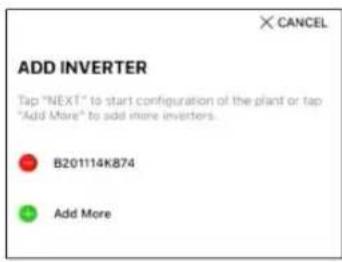
figure 6-6 Display the Added Inverter
Step 2 Fill in the plant information. The fields marked with * must be filled in.

figure 6-7 Entering Plant Information
Step 3 (Optional) Fill in the tariff information. The electricity price can be set to a specific value or Time-of-Use tariff.
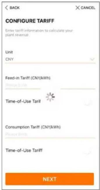
figure 6-8 Entering Tariff Information
Step 4 Fill in the end user's e-mail address. The first time you fill in the end user's e-mail address, the system will create an account for the end user and send an email to the end user. The end user can activate the account via the email.

The Distributor/installer creates plants for the end user and can manage the plants by default.
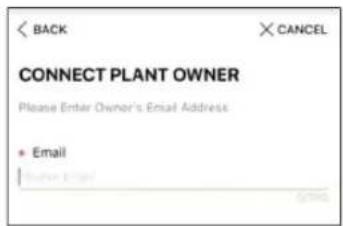
figure 6-9 Entering Owner's e-mail
Step 5 Tap NEXT to wait for the inverter to connect to the iSolarCloud.
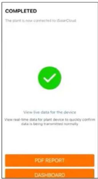
figure 6-10 Configuration Completed
Step 6 (Optional) Tab View live data for the device, tick Inverter or Total Plant Devices and tab ALL PLANTS OPEN. The clock symble indicates that the live data view function is successfully enabled. Tab the inverter to view the live data about voltage, current, power or curve.

Contact Sungrow service to enable live data function of devices. Once enabled, live data function is available for 3 hours per day by default. To make it available for 24 hours, contact SUNGROW.
Step 7 Tab BACK to the COMPLETED screen. Tab PDF REPORT to export the plant configuration report.
Step 8 Tab BACK to the COMPLETED screen. Tab DASHBOARD to return and manually refresh the page until the newly created plant is displayed with status commissioned.
-- End
7 iSolarCloud App
7.1 Brief Introduction
The iSolarCloud App can establish communication connection to the inverter via the WLAN, providing remote monitoring, data logging and near-end maintenance on the inverter. Users can also view inverter information and set parameters through the App.
* To achieve direct login via WLAN, the wireless communication module developed and manufactured by SUNGROW is required. The iSolarCloud App can also establish communication connection to the inverter via Ethernet connection.

- This manual describes only how to achieve near-end maintenance via WLAN direct connection.
- Screenshots in this manual are based on the V2.1.6 App for Android system, and the actual interfaces may differ.
7.2 Installing App
Method 1
Download and install the App through the following application stores:
- MyApp (Android, mainland China users)
- Google Play (Android, users other than mainland China ones)
- App Store (iOS)
Method 2
Scan the following QR code to download and install the App according to the prompt information.

The App icon appears on the home screen after installation.

natural_image
Weather icon showing a cloud with rays on orange background (no text or symbols)7.3 Account Registration
The account distinguishes two user groups, owners and retailer/installer.
- The owner can view plant information, create plants, set parameters, share plants, etc.
- The retailer/installer can help the owner to create plants, manage, install, or maintain plants, and manage users and organizations.
Step 1 Tap REGISTER to enter the registration screen.
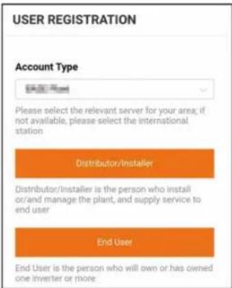
Step 2 Select the relevant server for your area.
Step 3 Select Owner or Retailer/Installer to enter the corresponding screen.
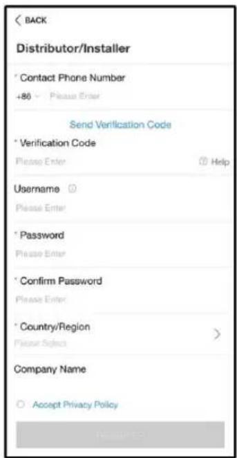
Step 4 Fill in the registration information, including email, verification code, password and affirmance and country (region). The retailer/installer has the permission to fill in the company name and the code of upper level retailer/installer.

The code of upper level retailer/installer can be obtained from the upper level retailer/installer. Only when your organization belongs to the upper level retailer/installer organization, can you fill in the corresponding code.
Step 5 Tick Accept Privacy Policy and tap Register to finish the registration operation.
-- End
7.4 Login
7.4.1 Requirements
The following requirements should be met:
• The AC and DC sides or the AC side of the inverter is powered-on.
- The WLAN function of the mobile phone is enabled.
- The mobile phone is within the coverage of the wireless network produced by the communication module.
7.4.2 Login Procedure
Step 1 For the WiFi-P2 module, press the multi-function button 3 times to enable the WLAN hotspot. No password is required and the valid time is 30 minutes.
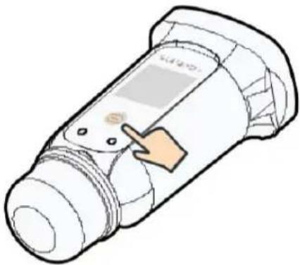
natural_image
Illustration of a handheld device with a pointing hand and a screen (no text or symbols)figure 7-1 Enabling the WLAN Hotspot
Step 2 Connect the mobile phone to the WLAN network named as "SG-xxxxxxxxxxx" (xxxxxxxxxx is the serial number indicated on the side of the communication module).
Step 3 Open the App to enter the login screen. Tap Local Access to enter the next screen.
Step 4 Tap Confirm, then enter the password and tap LOGIN. Or tap MANUAL CONNECTION at the bottom of the interface and select WiFi-P2, then enter the password and tap LOGIN.

- If the WiFi signal, serial number or inverter related data information cannot be found, unplug and reinsert the WiFi-P2 or press the multi-function button of the WiFi-P2 three times.
- The default account is "user" and the initial password is "pw1111" which should be changed for the consideration of account security. Tap "More" at the lower right corner on home page and choose "Change Password".
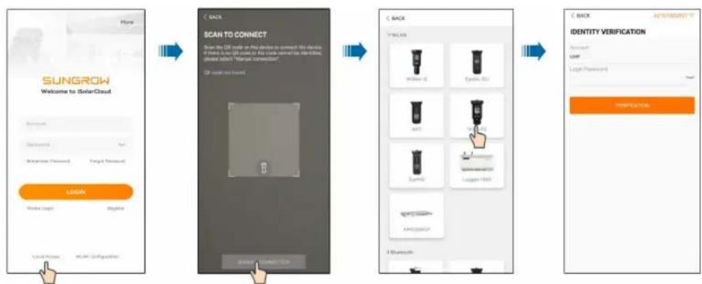
flowchart
graph LR
    A["SUNGROW\nWelcome to SolarCloud\nAccess\nAccess ID\nConnect User Password\nForward Password"] --> B["SCAN TO CONNECT\nFrom the DB node on the device to connect the device if there is no DB node in the device connected to Identification, please select "Open Connection" or "OK" based on a single point of connection"]
    B --> C["BACK\nType: 10.0\nWindows 2\nWindows 3\nWindows 4\nWindows 5\nWindows 6\nWindows 7\nWindows 8\nWindows 9\nWindows 10\nWindows 11\nWindows 12\nWindows 13\nWindows 14\nWindows 15\nWindows 16\nWindows 17\nWindows 18\nWindows 19\nWindows 20\nWindows 21\nWindows 22\nWindows 23\nWindows 24\nWindows 25\nWindows 26\nWindows 27\nWindows 28\nWindows 29\nWindows 30\nWindows 31\nWindows 32\nWindows 33\nWindows 34\nWindows 35\nWindows 36\nWindows 37\nWindows 38\nWindows 39\nWindows 40\nWindows 41\nWindows 42\nWindows 43\nWindows 44\nWindows 45\nWindows 46\nWindows 47\nWindows 48\nWindows 49\nWindows 50\nWindows 60\nWindows 61\nWindows 62\nWindows 63\nWindows 64\nWindows 65\nWindows 66\nWindows 67\nWindows 68\nWindows 69\nWindows 70\nWindows 71\nWindows 72\nWindows 73\nWindows 74\nWindows 75\nWindows 76\nWindows 77\nWindows 78\nWindows 79\nWindows 80\nWindows 81\nWindows 82\nWindows 83\nWindows 84\nWindows 85\nWindows 86\nWindows 87\nWindows 88\nWindows 89\nWindows 90\nWindows 91\nWindows 92\nWindows 93\nWindows 94\nWindows 95\nWindows 96\nWindows 97\nWindows 98\nWindows 99\nWindows 100"]
figure 7-2 WLAN Local Access
Step 5 If the inverter is not initialized, navigate to the quick setting screen to initialize the protection parameters. For details, please refer to "Initial Settings".
NOTICE
The "Country/Region" must be set to the country where the inverter is installed at. Otherwise, the inverter may report errors.
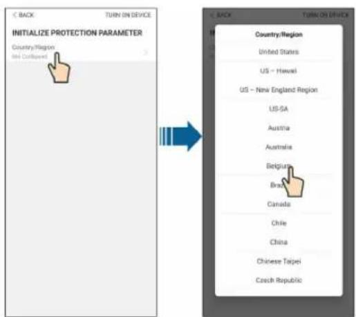
figure 7-3 WLAN Local Access
Step 6 After finishing the settings, tap TUNR ON DEVICE at the upper right corner and the device will be initialized. The App will send start instructions and the device will start and operate.
Step 7 After initialization settings, the App will return automatically to the home page.
-- End
7.5 Initial Settings
Tap Country/Region and select the country where the inverter is installed. The initialization is completed.
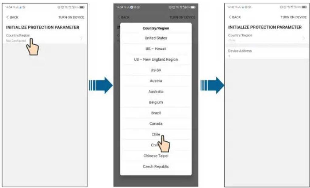

The actual initializing procedure may differ due to different countries. Please follow the actual App guidance.
7.6 Function Overview
The App provides parameter viewing and setting functions, as shown in the following figure.12
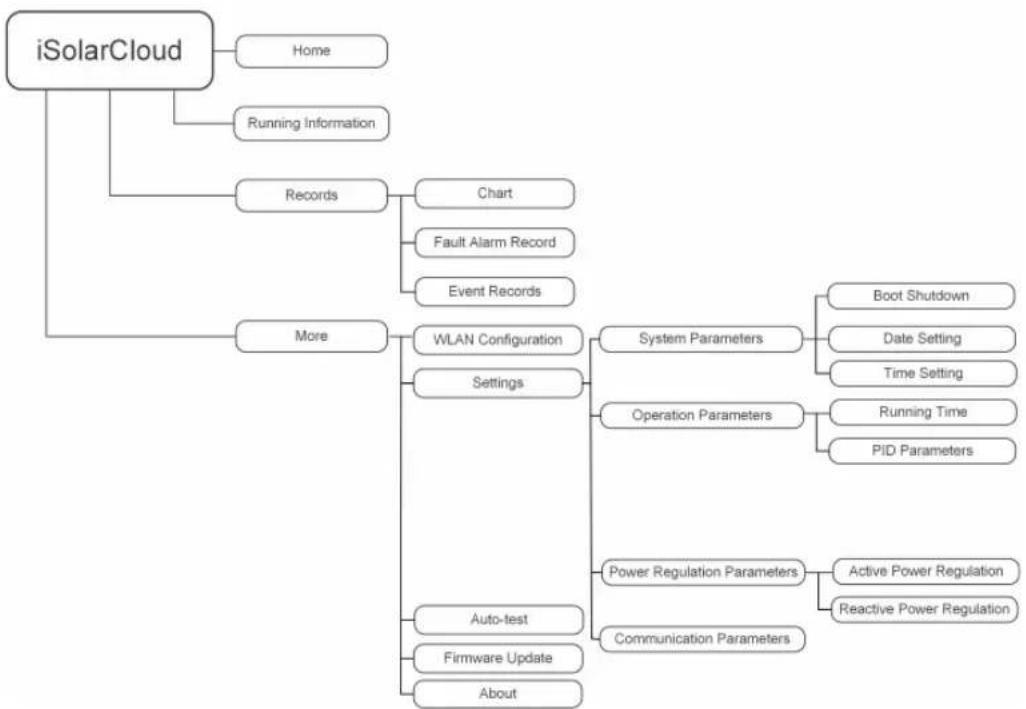
flowchart
graph TD
    A["iSolarCloud"] --> B["Home"]
    A --> C["Running Information"]
    A --> D["Records"]
    D --> E["Chart"]
    D --> F["Fault Alarm Record"]
    D --> G["Event Records"]
    A --> H["More"]
    H --> I["WLAN Configuration"]
    H --> J["Settings"]
    I --> K["System Parameters"]
    I --> L["Operation Parameters"]
    K --> M["Boot Shutdown"]
    K --> N["Date Setting"]
    K --> O["Time Setting"]
    L --> P["Running Time"]
    L --> Q["PID Parameters"]
    I --> R["Power Regulation Parameters"]
    I --> S["Communication Parameters"]
    I --> T["Auto-test"]
    I --> U["Firmware Update"]
    I --> V["About"]
figure 7-4 App Function Tree Map
7.7 Home
Home page of the App is shown in the following figure.
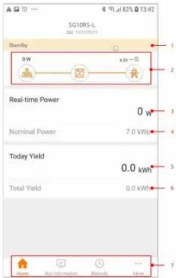
figure 7-5 Home
table 7-1 Home Page Description
| No. | Name | Description |
| 1 | Inverter state | Present operation state of the inverter |
| 2 | Energy flow chart | Shows the PV power generation power, feed-in power, etc.The line with an arrow indicates energy flow between connected devices, and the arrow pointing indicates energy flow direction. |
| 3 | Real-time power | Shows the present output power of the inverter. |
| 4 | Nominal power | Shows the installed power of the inverter. |
| 5 | Today yield | Shows today power generation of the inverter |
| 6 | Total yield | Shows accumulative power generation of the inverter |
| 7 | Navigation bar | Includes menus of "Home", "Run Infomation", "Records" and "More". |
If the inverter runs abnormally, the fault icon will appear on the upper left corner of the screen. Users can tap the icon to view detailed fault information and corrective measures.
7.8 Run Information
Tap Run Information on the navigation bar to enter the screen showing running information, slide the screen upwards to view all detailed information.
table 7-2 Description of Run Information
| Item | Description |
| Inverter Information | Shows basic information such as running state, on-grid running time, negative voltage to grid, bus voltage, internal air temperature, inverter efficiency, etc. |
| Input | Shows total DC power, voltage and current of MPPT1 ,MPPT2 and MPPT3. |
| Output | Shows daily/monthly/annual/total yield, total active/reactive/apparent power, total power factor, grid frequency, phase voltage and current. |
| Grid Information | Shows total export active power, total feed-in energy, total purchased energy. |
| Load Information | Shows total load active power. |
| Meter Information | Shows active power and phase active power of the meter. |
7.9 Records
Tap Records on the navigation bar to enter the screen showing event records, as shown in the following figure.
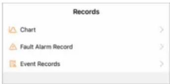
figure 7-6 Records
Chart
Tap Chart to enter the screen showing daily power generation, as shown in the following figure.
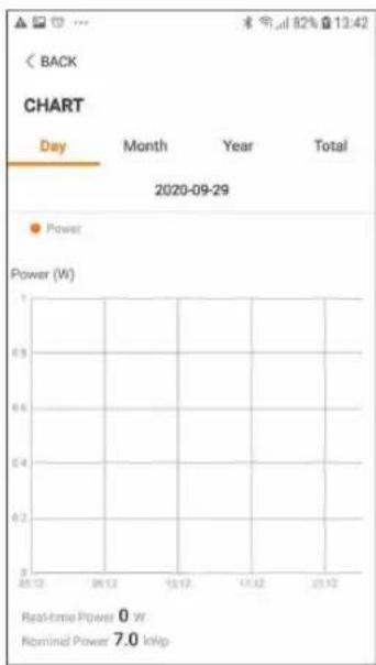
figure 7-7 Chart
The App displays power generation records in a variety of forms, including daily power generation graph, monthly power generation histogram, annual power generation histogram and total power generation histogram.
table 7-3 Description of Power Curve
| Item | Description |
| Daily | Daily curve that indicates the real-time power. |
| Month | Monthly curve that indicates daily yield and equivalent hours in a month. |
| Year | Annual curve that indicates monthly yield and equivalent hours in a year. |
| Total | A curve that indicates annual yield and equivalent hours since installation. |
Fault Alarm Record
Tap Fault Alarm Record to enter the screen, as shown in the following figure.
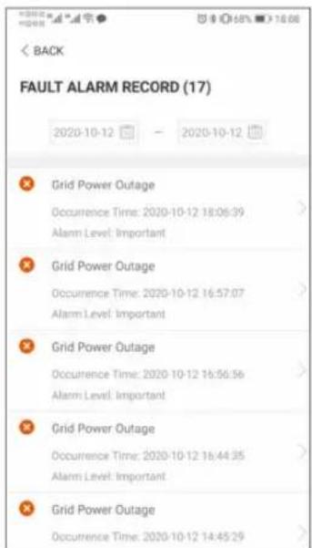
figure 7-8 Fault Alarm Record

Click to select a time segment and view corresponding records.
Select one of the records in the list and click the record, to view the detailed fault info as shown in following figure.
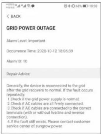
figure 7-9 Detailed Fault Alarm Information
Event Record
Tap Event Record to enter the screen, as shown in the following figure.
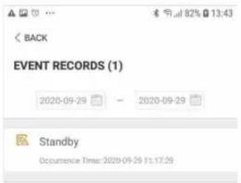
figure 7-10 Event Record

Click to select a time segment and view corresponding records.
7.10 More
Tap More on the navigation bar to enter the corresponding screen, as shown in the following figure.
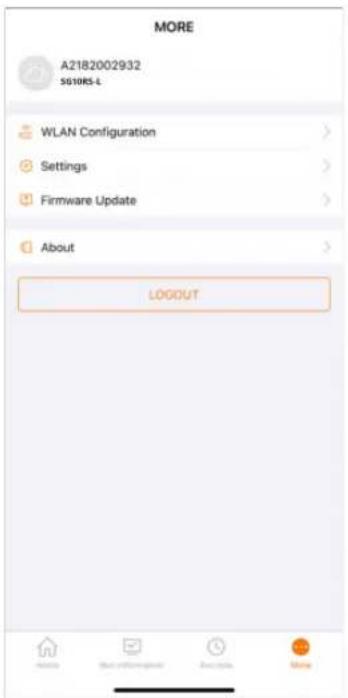
figure 7-11 More
In addition to viewing the WLAN configuration and App software version, the More screen supports the following operations:
- Set parameters including inverter system parameters, operation parameters, power regulation parameters and communication parameters.
- Upgrade inverter firmware.
7.10.1 System Parameters
Tap "Settings→System Parameters" to enter the corresponding interface, as shown in the following figure.
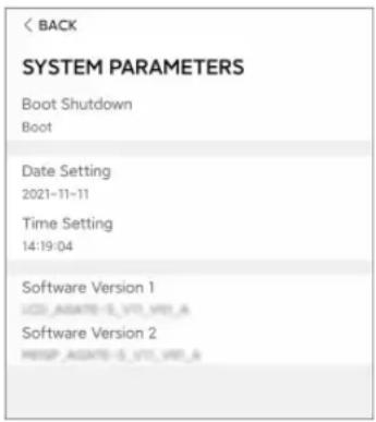
figure 7-12 System Parameters
* The image shown here is for reference only.
Boot/Shutdown
Tap Boot/Shutdown to send the boot/shutdown instruction to the inverter.
For Australia and New Zealand, when the DRM state is DRM0, the "Boot" option will be prohibited.
Date Setting/Time Setting
The correct system time is very important. Wrong system time will directly affect the data logging and power generation value. The clock is in 24-hour format.
Software Version
Version information of the current firmware.
7.10.2 Operation Parameters
Running Time
Tap "Settings→Operation Parameters→Running Time" to enter the corresponding screen, on which you can set "Connecting Time" and "Reconnecting Time".
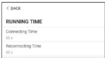
figure 7-13 Running Time
PID Parameters
Tap "Settings→Operation Parameters→PID Parameters" to enter the corresponding screen, on which you can set "PID Parameters".
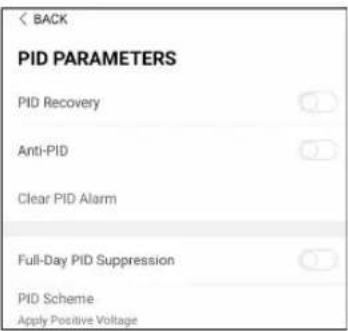
figure 7-14 PID Setting
table 7-4 PID Parameter Description
| Parameter | Description |
| PID Recovery | Set enabling/disabling of the PID night recovery function. PID night recovery function operates between 22:00 pm and 5:00 am by default. |
| Anti-PID | The Anti-PID function is performed during the day when connected to the grid. |
| Full-Day PID Suppression | The function is turned on and the PID is adjusted throughout the day. |
7.10.3 Power Regulation Parameters
Active Power Regulation
Tap “Settings→Power Regulation Parameters→Active Power Regulation” to enter the screen, as shown in the following figure.
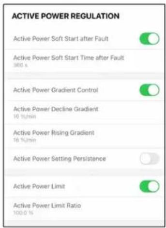
figure 7-15 Active Power Regulation
table 7-5 Description of Active Power Regulation Parameters
| Parameter | Description Range | |
| Active Power Soft Start after Fault | Switch for activating/deactivating the function of active power soft start after a fault occurs | On/Off |
| Active Power Soft Start Time after Fault | The soft start time required for raising active power from 0 to rated value after a fault occurs | 1 s–1200 s |
| Active Power Gradient Control | Set whether to enable active power gradient control | On/Off |
| Active Power Decline Gradient | Decline gradient of inverter active power per minute | 1 %/min–6000 %/min |
| Active Power Rising Gradient | Rising gradient of inverter active power per minute | 1 %/min–6000 %/min |
| Active Power Setting Persistence | Switch for activating/deactivating the function of active power setting persistence | On/Off |
| Active Power Limit | Switch for limiting active power | On/Off |
| Active Power Limit Ratio | The ratio of active power limit to rated power percentage | 0.0 %–100.0 % |
Reactive Power Regulation
Tap "Settings→Power Regulation Parameters→Reactive Power Regulation" to enter the screen, as shown in the following figure.
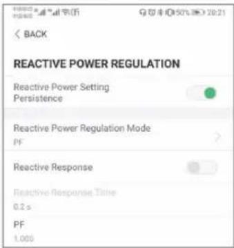
figure 7-16 Reactive Power Regulation
table 7-6 Description of Reactive Power Regulation Parameters
| Parameter | Description Range | |
| Reactive Power Setting Persistence | Switch for activating/deactivating the function of reactive power setting persistence | On/Off |
| Reactive Power Regulation Mode | Off/PF/Qt/Q(P)/Q(U) | Off/PF/Qt/Q(P)/Q(U) |
| Reactive Response | Switch for activating/deactivating the function of reactive response | On/Off |
| Reactive Response Time | Time for reactive response | 0.1 s-600 s |
"Off" Mode
The reactive power regulation function is disabled. The PF is fixed at +1.000.
"PF" Mode
The power factor (PF) is fixed and the reactive power is regulated by the parameter PF. The PF ranges from 0.8 leading to 0.8 lagging.
- Leading: The inverter supplies reactive power to the grid.
- Lagging: The inverter absorbs reactive power from the grid.
"Qt" Mode
In the Qt mode, the reactive power can be regulated by the parameter Q-Var limits (in %). The system rated reactive power is fixed, the system injects reactive power according to the delivered reactive power ratio. The "Reactive Power Ratio" is set through the App.
The setting range of the reactive power ratio is from -100 % to 100 %, corresponding to the ranges of inductive and capacitive reactive power regulation respectively.
"Q(P)" Mode
The PF of the inverter output varies in response to the output power of the inverter.
table 7-7 "Q(P)" Mode Parameters Explanation
| Parameter Explanation Range | ||
| Q(P) Curve Select corresponding curve according to local regulations | A, B, C | |
| QP_P1 Output power at point P1 on the Q(P) mode curve (in %) | 0.0 %-100.0 % | |
| QP_P2 Output power at point P2 on the Q(P) mode curve (in %) | 20.0 %-100.0 % | |
| QP_P3 Output power at point P3 on the Q(P) mode curve (in %) | 20.0 %-100.0 % | |
| QP_K1 Power factor at point P1 on the Q(P) mode curve Curve | A/C: 0.800 to 1.000 | |
| QP_K2 Power factor at point P2 on the Q(P) mode curve | ||
| QP_K3 Power factor at point P3 on the Q(P) mode curve | Curve B: -0.600 to 0.600 | |
| QP_EnterVoltage | Voltage for Q(P) function activation (in %) 100.0 %-110.0 % | |
| QP_ExitVoltage | Voltage for Q(P) function deactivation (in %) 90.0 %-100.0 % | |
| QP_ExitPower | Power for Q(P) function deactivation (in %) 1.0 %-100.0 % | |
| QP_EnableMode | Unconditional activation/deactivation of Q(P) function | Yes, No |
* Curve C is reserved and consistent with Curve A currently.
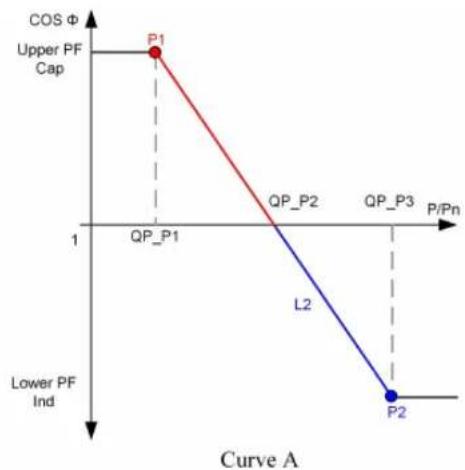
line
| Point | P/Pn | Cos Φ | |-------|------|-------| | P1 | 1 | High | | QP_P1 | | Low | | QP_P2 | | Low | | QP_P3 | | Low | | L2 | | Low | | P2 | | Low |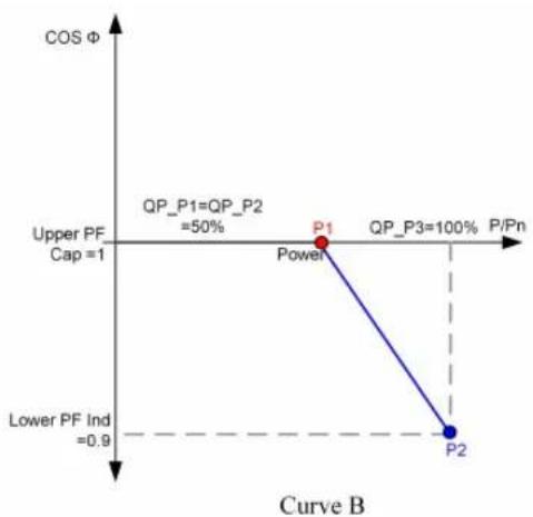
line
| Point | P/Pn (%) | Cos Φ | |---|---|---| | Power | 100 | 50 | | P1 | 100 | 50 | | P2 | 100 | 0.9 | | Upper PF Cap = 1 | | | | Lower PF Ind = 0.9 | | | | Curve B: QP_P1=QP_P2 =50%; QP_P3=100%figure 7-17 Reactive Power Regulation Curve in Q(P) Mode
"Q(U)" Mode
The reactive power output of the inverter varies in response to the grid voltage.
table 7-8 "Q(U)" Mode Parameter Explanation
| Parameter | Explanation Range | |
| Q(U) curve | Select corresponding curve according to local regulations | A, B, C |
| Hysteresis Ratio | Voltage hysteresis ratio on the Q(U) mode curve | 0.0 %-5.0 % |
| QU_V1 | Grid voltage limit at point P1 on the Q(U) mode curve (in %) | 80.0 %-100.0 % |
| QU_V2 | Grid voltage limit at point P2 on the Q(U) mode curve (in %) | 80.0 %-100.0 % |
| QU_V3 | Grid voltage limit at point P3 on the Q(U) mode curve (in %) | 0.0 %-120.0 % |
| QU_V4 | Grid voltage limit at point P4 on the Q(U) mode curve (in %) | 0.0 %-120.0 % |
| QU_Q1 | Value of Q/Sn at point P1 on the Q(U) mode curve (in %) | -60.0 % to 0.0 % |
| QU_Q2 | Value of Q/Sn at point P2 on the Q(U) mode curve (in %) | 0.0 % to 60.0 % |
| QU_Q3 | Value of Q/Sn at point P3 on the Q(U) mode curve (in %) | -60.0 % to 60 % |
| QU_Q4 | Value of Q/Sn at point P4 on the Q(U) mode curve (in %) | 0.0 % to 60.0 % |
| QU_EnterPower | Active power for Q(U) function activation (in %) | 20.0 %-100.0 % |
| QU_ExitPower | Active power for Q(U) function deactivation (in %) | 1.0 %-20.0 % |
| QU_EnableMode | Unconditional activation/deactivation of Q(U) function | Yes, No, Yes (Limited by PF) |
| QU_Limited PF Value | Preset PF value 0–1 | |
* Curve C is reserved and consistent with Curve A currently.
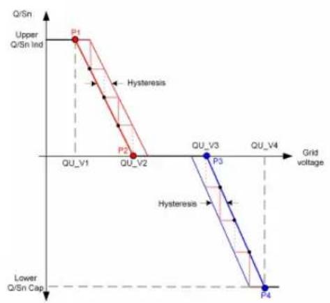
line
| Point | Q/Sn Level | Grid Voltage | |-------|------------|--------------| | P1 | Upper | QU_V1 | | P2 | Lower | QU_V2 | | P3 | Lower | QU_V3 | | P4 | Lower | QU_V4 |Curve A
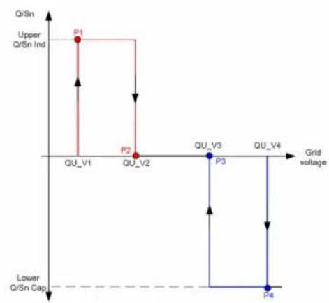
line
| Stage | Grid voltage | Q/Sn Ind | | :--- | :--- | :--- | | P1 | QU_V1 | Upper | | P2 | QU_V2 | Lower | | P3 | QU_V3 | Lower | | P4 | QU_V4 | Lower |Curve B
figure 7-18 Reactive Power Regulation Curve in Q(U) Curve
7.10.4 Communication Parameters
Tap "Settings→Communication Parameters" to enter the corresponding screen, as shown in the following figure. The device address ranges from 1 to 246.
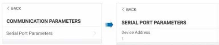
figure 7-19 Communication Parameters
To avoid download failure due to poor on-site network signal, it is recommended to download the firmware package to the mobile device in advance.
Step 1 Enable the "Mobile data" of the mobile device.
Step 2 Open the App, enter the account and password on the login screen. Tap Login to enter the home screen.
Step 3 Tap "More→Firmware Download" to enter corresponding screen on which you can view the device list.
Step 4 Select the device model before downloading the firmware. Tap the device name in the device list to enter the firmware upgrade package detail interface, and tape behind the firmware upgrade package to download it.
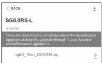
Step 5 Return to the Firmware Download screen, tap ↓ in the upper right corner of the screen to view the downloaded firmware upgrade package.
Step 6 Login the App via local access mode. Refer to "7.4 Login".
Step 7 Tap More on the App home screen and then tap Firmware Update.
Step 8 Tap the upgrade package file, a prompt box will pop up asking you to upgrade the firmware with the file, tap CONFIRM to perform the firmware upgrade.
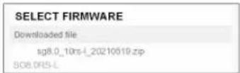
Step 9 Wait for the file to be uploaded. When the upgrade is finished, the interface will inform you of the upgrade completion. Tap Complete to end the upgrade.
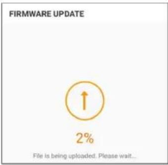
-- End
8 System Decommissioning
8.1 Disconnecting the Inverter
CAUTION
Danger of burns!
Even if the inverter is shut down, it may still be hot and cause burns. Wear protective gloves before operating the inverter after it cools down.
For maintenance or other service work, the inverter must be switched off. Proceed as follows to disconnect the inverter. Lethal voltages or damage to the inverter will follow if otherwise.
Step 1 Disconnect the external AC circuit breaker and prevent it from inadvertent reconnection.
Step 2 Rotate the DC switch to the "OFF" position for disconnecting all of the PV string inputs.
Step 3 Wait about 10 minutes until the capacitors inside the inverter completely discharge.
Step 4 Ensure that the DC cable is current-free with a current clamp.
-- End
8.2 Dismantling the Inverter
CAUTION
Risk of burn injuries and electric shock!
After the inverter is powered off for 10 minutes, measure the voltage and current with professional instrument. Only when there is no voltage nor current can operators who wear protective equipment operate and maintain the inverter.
- Before dismantling the inverter, disconnect the inverter from both AC and DC power sources.
- If there are more than two layers of inverter DC terminals, dismantle the outer DC connectors before dismantling the inner ones.
- If the original packing materials are available, put the inverter inside them and then seal them using adhesive tape. If the original packing materials are not available, put the inverter inside a cardboard box suitable for the weight and size of this inverter and seal it properly.
i
Step 1 Refer to "5 Electrical Connection", for the inverter disconnection of all cables in reverse steps. In particular, when removing the DC connector, use an MC4 wrench to loosen the locking parts and install waterproof plugs.
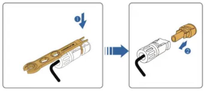
Step 2 Refer to "4 Mechanical Mounting", to dismantle the inverter in reverse steps.
Step 3 If necessary, remove the wall-mounting bracket from the wall.
Step 4 If the inverter will be used again in the future, please refer to "3.2 Inverter Storage" for a proper conservation.
-- End
8.3 Disposal of Inverter
Users take the responsibility for the disposal of the inverter.
WARNING
Please scrap the inverter in accordance with relevant local regulations and standards to avoid property losses or casualties.
NOTICE
Some parts of the inverter may cause environmental pollution. Please dispose of them in accordance with the disposal regulations for electronic waste applicable at the installation site.
9 Troubleshooting and Maintenance
9.1 Troubleshooting
Once the inverter fails, the fault information is displayed on the App interface. If the inverter is equipped with an LCD screen, the fault information can be viewed on it.
The fault codes and troubleshooting methods of all PV inverters are detailed in the table below, and only some of the faults may occur to the model you purchased. When a fault occurs, you can check the fault information according to the fault code on the mobile app.
| Fault Code Fault Name Corrective Measures | ||
| 2, 3, 14, 15 | Grid Overvoltage | Generally, the inverter will be reconnected to the grid after the grid returns to normal. If the fault occurs repeatedly:1. Measure the actual grid voltage, and contact the local electric power company for solutions if the grid voltage is higher than the set value.2. Check whether the protection parameters are appropriately set via the App or the LCD. Modify the overvoltage protection values with the consent of the local electric power operator.3. Contact Sungrow Customer Service if the preceding causes are ruled out and the fault persists. |
| 4, 5 | Grid Undervoltage | Generally, the inverter will be reconnected to the grid after the grid returns to normal. If the fault occurs repeatedly:1. Measure the actual grid voltage, and contact the local electric power company for solutions if the grid voltage is lower than the set value.2. Check whether the protection parameters are appropriately set via the App or the LCD.3. Check whether the AC cable is firmly in place.4. Contact Sungrow Customer Service if the preceding causes are ruled out and the fault persists. |
| Fault Code | Fault Name | Corrective Measures |
| 8 | Grid Overfrequency | Generally, the inverter will be reconnected to the grid after the grid returns to normal. If the fault occurs repeatedly:1. Measure the actual grid frequency, and contact the local electric power company for solutions if the grid frequency is beyond the set range.2. Check whether the protection parameters are appropriately set via the App or the LCD.3. Contact Sungrow Customer Service if the preceding causes are ruled out and the fault persists. |
| 9 | Grid Underfrequency | |
| 10 | Grid Power Outage | Generally, the inverter will be reconnected to the grid after the grid returns to normal. If the fault occurs repeatedly:1. Check whether the grid supplies power reliably.2. Check whether the AC cable is firmly in place.3. Check whether the AC cable is connected to the correct terminal (whether the live wire and the N wire are correctly in place).4. Check whether the AC circuit breaker is connected.5. Contact Sungrow Customer Service if the preceding causes are ruled out and the fault persists. |
| 12 | Excess Leakage Current | 1. The fault can be caused by poor sunlight or damp environment, and generally the inverter will be reconnected to the grid after the environment is improved.2. If the environment is normal, check whether the AC and DC cables are well insulated.3. Contact Sungrow Customer Service if the preceding causes are ruled out and the fault persists. |
| 13 Grid Abnormal | Generally, the inverter will be reconnected to the grid after the grid returns to normal. If the fault occurs repeatedly:1. Measure the actual grid, and contact the local electric power company for solutions if the grid parameter exceeds the set range.2. Contact Sungrow Customer Service if the preceding causes are ruled out and the fault persists. | |
| Fault Code Fault Name Corrective Measures | ||
| 17 | Grid Voltage Imbalance | Generally, the inverter will be reconnected to the grid after the grid returns to normal. If the fault occurs repeatedly:1. Measure the actual grid voltage. If grid phase voltages differ greatly, contact the electric power company for solutions.2. If the voltage difference between phases is within the permissible range of the local power company, modify the grid voltage imbalance parameter through the App or the LCD.3. Contact Sungrow Customer Service if the preceding causes are ruled out and the fault persists. |
| 28, 29, 208, 212, 448-479 | PV Reserve Connection Fault | 1. Check whether the corresponding string is of reverse polarity. If so, disconnect the DC switch and adjust the polarity when the string current drops below 0.5 A.2. Contact Sungrow Customer Service if the preceding causes are ruled out and the fault persists.*The code 28 to code 29 are corresponding to PV1 to PV2 respectively.*The code 448 to code 479 are corresponding to string 1 to string 32 respectively. |
| 532-547, 564-579 | PV Reverse Connection Alarm | 1. Check whether the corresponding string is of reverse polarity. If so, disconnect the DC switch and adjust the polarity when the string current drops below 0.5 A.2. Contact Sungrow Customer Service if the preceding causes are ruled out and the alarm persists.*The code 532 to code 547 are corresponding to string 1 to string 16 respectively.*The code 564 to code 579 are corresponding to string 17 to string 32 respectively. |
Fault Code Fault Name Corrective Measures
| 548-563, 580-595 | PV Abnormal Alarm | Check whether the voltage and current of the inverter is abnormal to determine the cause of the alarm.1. Check whether the corresponding module is sheltered. If so, remove the shelter and ensure module cleanness.2. Check whether the battery board wiring is loose, if so, make it reliably connected.3. Check if the DC fuse is damaged. If so, replace the fuse.4. Contact Sungrow Customer Service if the preceding causes are ruled out and the alarm persists.*The code 548 to code 563 are corresponding to string 1 to string 16 respectively.*The code 580 to code 595 are corresponding to string 17 to string 32 respectively. |
| 37 | Excessively High Ambient Temperature | Generally, the inverter will resume operation when the internal or module temperature returns to normal. If the fault persists:1. Check whether the ambient temperature of the inverter is too high;2. Check whether the inverter is in a well-ventilated place;3. Check whether the inverter is exposed to direct sunlight. Shield it if so;4. Check whether the fan is running properly. Replace the fan if not;5. Contact Sungrow Power Customer Service if the fault is due to other causes and the fault persists. |
| 43 | Excessively Low Ambient Temperature | Stop and disconnect the inverter. Restart the inverter when the ambient temperature rises within the operation temperature range. |
| Fault Code Fault Name Corrective Measures | ||
| 39 | Low System Insulation Resistance | Wait for the inverter to return to normal. If the fault occurs repeatedly:1. Check whether the ISO resistance protection value is excessively high via the app or the LCD, and ensure that it complies with the local regulations.2. Check the resistance to ground of the string and DC cable. Take corrective measures in case of short circuit or damaged insulation layer.3. If the cable is normal and the fault occurs on rainy days, check it again when the weather turns fine.4. If there are batteries, check whether battery cables are damaged and whether terminals are loose or in poor contact. If so, replace the damaged cable and secure terminals to ensure a reliable connection.5. Contact Sungrow Customer Service if the preceding causes are ruled out and the fault persists. |
| 106 | Grounding Cable Fault | 1. Check whether the AC cable is correctly connected.2. Check whether the insulation between the ground cable and the live wire is normal.3. Contact Sungrow Customer Service if the preceding causes are ruled out and the fault persists. |
| 323 Grid Confrontation | 1. Check whether the output port is connected to actual grid. Disconnect it from the grid if so.2. Contact Sungrow Customer Service if the preceding causes are ruled out and the fault persists. | |
| 75 | Inverter Parallel Communication Alarm | 1. Check whether the communication cable and the terminals are abnormal. If so, correct them to ensure reliable connection.2. Reconnect the communication cable of the meter.3. Contact Sungrow Customer Service if the preceding causes are ruled out and the alarm persists. |
| 7, 11, 16, 19–25, 30–34, 36,38, 40–42, 44–50, 52–58, 60–69, 85, 87, 92,93, 100–105,107–114, 116–124, 200–211,248–255, 300–322, 324–328,401–412, 600–603, 605, 608,612, 616, 620,622–624, 800,802, 804, 807,1096–1118 | System Fault | 1. Wait for the inverter to return to normal.2. Disconnect the AC and DC switches, and disconnect the battery side switches if there are batteries. Close the AC and DC switches in turn 15 minutes later and restart the system.3. Contact Sungrow Customer Service if the preceding causes are ruled out and the fault persists. |
| 59, 70–74, 76–83, 89, 216–218, 220–233,432–434, 500–513, 515–518,635–638, 900,901, 910, 911,996 | System Alarm | 1. The inverter can continue running.2. Check whether the related wiring and terminal are abnormal, check whether there are any foreign materials or other environmental abnormalities, and take corresponding corrective measures when necessary.3. If the fault persists, please contact Sungrow Power Customer Service. |
| 264-283 | MPPT Reverse Connection | 1. Check whether the corresponding string is of reverse polarity. If so, disconnect the DC switch and adjust the polarity when the string current drops below 0.5 A.2. Contact Sungrow Customer Service if the preceding causes are ruled out and the fault persists.*The code 264 to code 279 are corresponding to string 1 to string 20 respectively. |
| Fault Code | Fault Name | Corrective Measures |
| 332-363 | Boost Capacitor Overvoltage Alarm | 1. The inverter can continue running.2. Check whether the related wiring and terminals are abnormal, check whether there are any foreign materials or other environmental abnormalities, and take corresponding corrective measures when necessary.If the fault persists, please contact Sungrow Power Customer Service. |
| 364-395 | Boost Capacitor Overvoltage Fault | 1. Disconnect the AC and DC switches, and disconnect the battery side switches if there are batteries. Close the AC and DC switches in turn 15 minutes later and restart the system.2. If the fault persists, please contact Sungrow Power Customer Service. |
| 1548-1579 | String Current Reflux | 1. Check whether the number of PV modules of the corresponding string is less than other strings. If so, disconnect the DC switch and adjust the PV module configuration when the string current drops below 0.5 A.2. Check whether the PV module is shaded;3. Disconnect the DC switch to check whether the open circuit voltage is normal when the string current drops below 0.5 A. If so, check the wiring and configuration of the PV module,4. Check whether the orientation of the PV module is abnormal. |
| Fault Code Fault Name Corrective Measures | ||
| 1600 - 1615,1632 - 1655 | PV GroundingFault | 1. When the fault occurs, it is forbidden to directly disconnect the DC switch and unplug PV terminals when the direct current is greater than 0.5 A;2. Wait until the direct current of the inverter falls below 0.5 A, then disconnect the DC switch and unplug the faulty strings;3. Do not reinsert the faulty strings before the grounding fault is cleared;4. If the fault is not caused by the foregoing reasons and still exists, contact Sungrow Customer Service. |
| 1616 | System HardwareFault | 1. It is prohibited to disconnect the DC switch when the DC current is greater than 0.5 A when the fault occurs.2. Disconnect the DC switch only when the inverter DC side current drops below 0.5 A.3. It is prohibited to power up the inverter again. Please contact Sungrow Customer Service. |
9.2 Maintenance
9.2.1 Maintenance Notices
The DC switch can be secured with a lock in the OFF position or a certain angle beyond the OFF position.(For countries "AU" and "NZ")
! DANGER
Risk of inverter damage or personal injury due to incorrect service!
- Be sure to use special insulation tools when perform high-voltage operations.
- Before any service work, first disconnect the grid-side AC circuit breaker and check the inverter status. If the inverter indicator is off, please wait until night to disconnect the DC switch. If the inverter indicator is on, directly disconnect the DC switch.
• After the inverter is powered off for 10 minutes, measure the voltage and current with professional instrument. Only when there is no voltage nor current can operators who wear protective equipment operate and maintain the inverter
• Even if the inverter is shut down, it may still be hot and cause burns. Wear protective gloves before operating the inverter after it cools down. - When maintaining the product, it is strictly prohibited to open the product if there is an odor or smoke or if the product appearance is abnormal. If there is no odor, smoke, or obvious abnormal appearance, repair or restart the inverter according to the alarm corrective measures. Avoid standing directly in front of the inverter during maintenance.
CAUTION
To prevent misuse or accidents caused by unrelated personnel: Post prominent warning signs or demarcate safety warning areas around the inverter to prevent accidents caused by misuse.
NOTICE
Restart the inverter only after removing the fault that impairs safety performance. As the inverter contains no component parts that can be maintained, never open the enclosure, or replace any internal components.
To avoid the risk of electric shock, do not perform any other maintenance operations beyond those described in this manual. If necessary, contact your distributor first. If the problem persists, contact SUNGROW. Otherwise, the losses caused is not covered by the warranty.
NOTICE
Touching the PCB or other static sensitive components may cause damage to the device.
- Do not touch the circuit board unnecessarily.
- Observe the regulations to protect against electrostatic and wear an anti-static wrist strap.
9.2.2 Routine Maintenance
| Item Method Period | ||
| Device clean | Check the temperature and dust of the device. Clean the device enclosure if necessary. | Six months to a year (depending on the dust con- tents in air) |
| Electrical connection | Check whether all cable are firmly connected in place.Check whether there is damage to the cables, especially the surface in contact with metal. | 6 months after commissioning and then once or twice a year |
| General status of the system | • Visual check for any damage or deformation of the microinverter.• Check any abnormal noise during the operation.• Check each operation parameter.• Be sure that nothing covers the heat sink of the device. | Every 6 months |
10 Appendix
10.1 Technical Data
| Parameter SG7.5RS-L SG8.0RS-L | |
| Input (DC) | |
| Recommended max. PV input power | 11.25 kWp 12 kWp |
| Max. PV input voltage 600 V | |
| Min. operating PV vol-tage / Start-up input voltage | 40 V / 50 V |
| Rated PV input voltage 360 V | |
| MPP voltage range 40 V - 560 V | |
| MPP voltage range for rated power | 250 - 480V |
| No. of independent MPP inputs | 2 |
| Default No. of PV strings per MPPT | 1/2 |
| Max. PV input current | 48 A (16 A / 32 A) |
| Max.DC Short-circuit current | 60 A (20 A /40 A) |
| Output (AC) | |
| Rated AC output power | 75000 W 8000 W |
| Max. AC output power | 75000 VA 8000 VA |
| Rated AC output cur- rent (at 220 V) | 34.1 A 36.4 A |
| Max. AC output current | 34.1 A 36.4 A |
| Rated AC voltage 220 V / 240 V | |
| AC voltage range | 154 V - 276 V |
| Rated grid frequency / Grid frequency range | 50 Hz / 45 Hz - 55 Hz60 Hz / 55 Hz - 65 Hz |
| Harmonic (THD) | < 3 % (at rated power) |
| Power factor at rated power / Adjustable power factor | > 0.99 / 0.8 leading - 0.8 lagging |
| Feed-in phases / Connection phases | 1 / 1 |
| Efficiency | |
| Max. efficiency / European efficiency | 97.8 % / 97.3 % 97.8 % / 97.3 % |
| Protection | |
| Grid monitoring | Yes |
| DC reverse polarity protection | Yes |
| AC short-circuit protection | Yes |
| Leakage current protection | Yes |
| DC switch | Yes |
| PV string current monitoring | Yes |
| PID Zero | Yes |
| Arc fault circuit interrupter (AFCI) | Yes |
| Surge protection | DC Type II, AC Type II |
| Protective Class I | |
| Overvoltage Category | DC II/AC III |
| Active Anti-Islanding Method | Frequency Shift |
| General Data | |
| Dimensions (W x H x D) 525 mm x 365 mm x 170 mm | |
| Weight | 18 kg |
| Mounting method | Wall-mounting bracket |
| Topology Transformerless | |
| Degree of protection IP65 | |
| Operating ambient temperature range | -25°C to +60°C |
| Allowable relative humidity range (non-condensing) | 0–100 % |
| Max. operating altitude 4000 m | |
| Cooling method | Natural cooling |
| Display | LED digital display & LED indicator |
Parameter SG7.5RS-L SG8.0RS-L
| Communication | WLAN |
| DC connection type | MC4 Compatible Connector (Max. 6 mm) |
| AC connection type | OT Terminal (Max. 16 mm) |
| Grid compliance ABNT NBR 16150, PORTARIA N° 140, DE 21 DE MARÇO DE 2022 | |
| Grid Support | Active & reactive power control and power ramp rate control |
Parameter SG9.0RS-L SG10RS-L
| Input (DC) | |
| Recommended max. PV input power | 13.5 kWp 15 kWp |
| Max. PV input voltage 600 V | |
| Min. operating PV vol-tage / Start-up input voltage | 40 V / 50 V |
| Rated PV input voltage 360 V | |
| MPP voltage range 40 V - 560 V | |
| MPP voltage range for rated power | 280 - 480V 310 - 480V |
| No. of independent MPP inputs | 3 |
| Default No. of PV strings per MPPT | 1 |
| Max. PV input current | 48 A (16 A / 16 A / 16 A) |
| Max.DC Short-circuit current | 60 A (20 A / 20 A / 20 A) |
| Output (AC) | |
| Rated AC output power | 9000 W 10000 W |
| Max. AC output power | 9000 VA 10000 VA |
| Rated AC output cur-rent (at 220 V) | 41 A 45.5 A |
| Max. AC output current | 41 A 45.5 A |
| Rated AC voltage 220 V / 240 V | |
| AC voltage range | 154 V - 276 V |
| Rated grid frequency / Grid frequency range | 50 Hz / 45 Hz - 55 Hz60 Hz / 55 Hz - 65 Hz |
| Parameter SG9.0RS-L SG10RS-L | |
| Harmonic (THD) | < 3 % (at rated power) |
| Power factor at rated power / Adjustable power factor | > 0.99 / 0.8 leading - 0.8 lagging |
| Feed-in phases / Connection phases | 1 / 1 |
| Efficiency | |
| Max. efficiency / Euro-pean efficiency | 97.8 % / 97.4 % 97.8 % / 97.4 % |
| Protection | |
| Grid monitoring | Yes |
| DC reverse polarity protection | Yes |
| AC short-circuit protection | Yes |
| Leakage current protection | Yes |
| DC switch | Yes |
| PV string current monitoring | Yes |
| PID Zero | Yes |
| Arc fault circuit inter-rupter (AFCI) | |
| Surge protection | DC Type II, AC Type II |
| Protective Class I | |
| Overvoltage Category | DC II/AC III |
| Active Anti-Islanding Method | Frequency Shift |
| General Data | |
| Dimensions (W x H x D) | 525 mm x 365 mm x 170 mm |
| Weight | 18 kg |
| Mounting method | Wall-mounting bracket |
| Topology Transformerless | |
| Degree of protection | IP65 |
| Operating ambient tem-perature range | -25°C to +60°C |
| Allowable relative hu-midity range (non-condensing) | 0–100 % |
| Max. operating altitude 4000 m | |
| Cooling method | Natural cooling |
| Display | LED digital display & LED indicator |
| Communication | WLAN |
| DC connection type | MC4 Compatible Connector (Max. 6 mm) |
| AC connection type | OT Terminal (Max. 16 mm) |
| Grid compliance ABNT NBR 16150, PORTARIA N° 140, DE 21 DE MARÇO DE 2022 | |
| Grid Support | Active & reactive power control and power ramp rate control |
10.2 Quality Assurance
When product faults occur during the warranty period, SUNGROW will provide free service or replace the product with a new one.
Evidence
During the warranty period, the customer shall provide the product purchase invoice and date. In addition, the trademark on the product shall be undamaged and legible. Otherwise, SUNGROW has the right to refuse to honor the quality guarantee.
Conditions
• After replacement, unqualified products shall be processed by SUNGROW.
- The customer shall give SUNGROW a reasonable period to repair the faulty device.
Exclusion of Liability
In the following circumstances, SUNGROW has the right to refuse to honor the quality guarantee:
- The free warranty period for the whole machine/components has expired.
- The device is damaged during transport.
- The device is incorrectly installed, refitted, or used.
- The device operates in harsh conditions beyond those described in this manual.
- The fault or damage is caused by installation, repairs, modification, or disassembly performed by a service provider or personnel not from SUNGROW.
- The fault or damage is caused by the use of non-standard or non-SUNGROW components or software.
- The installation and use range are beyond stipulations of relevant international standards.
- The damage is caused by unexpected natural factors.
For faulty products in any of above cases, if the customer requests maintenance, paid maintenance service may be provided based on the judgment of SUNGROW.

Product data such as product dimensions are subject to change without prior notice. The latest documentation from SUNGROW should take precedence in case of any deviation.
10.3 Contact Information
In case of questions about this product, please contact us.
We need the following information to provide you the best assistance:
- Model of the device
- Serial number of the device
- Fault code/name
- Brief description of the problem
For detailed contact information, please visit: https://en.sungrowpower.com/contactUS
- All Rights Reserved
- Trademarks
- Software Licenses
- About This Manual
- Validity
- Target Group
- How to Use This Manual
- Security Declaration
- Symbols
- ! DANGER
- WARNING
- CAUTION
- NOTICE
- Contents
- All Rights Reserved ....I
- About This Manual....II
- Safety Instructions ....1
- Product Description ....8
- Unpacking and Storage 20
- Mechanical Mounting 22
- Electrical Connection ....32
- Commissioning 49
- iSolarCloud App 66
- System Decommissioning 86
- Troubleshooting and Maintenance 88
- Appendix 98
- Safety Instructions
- i
- Unpacking and Inspection
- ! WARNING
- Installation Safety
- Electrical Connection Safety
- Operation Safety
- Maintenance Safety
- Disposal Safety
- Product Description
- System Introduction
- Product Introduction
- Model Description
- Appearance
- Dimensions
- Symbols on Product
- LED Panel
- Circuit Diagram
- Function Description
- Basic Function
- - Protection Function
- DRM ("AU"/"NZ")
- Mode Explanation
- Feed-in Limitation
- PID Zero
- AFCI Function (Optional)
- Automatic reconnection
- Unpacking and Storage
- Unpacking and Inspection
- Inverter Storage
- Mechanical Mounting
- Safety During Mounting
- Location Requirements
- Installation Environment Requirements
- Carrier Requirements
- Angle Requirements
- Clearance Requirements
- Installation Tools
- Moving the Inverter
- Installing the Inverter
- Electrical Connection
- Safety Instructions
- Terminal Description
- Electrical Connection Overview
- External Protective Grounding Connection
- External Protective Grounding Requirements
- Connection Procedure
- AC Cable Connection
- AC Side Requirements
- AC Circuit Breaker
- Residual Current Monitoring Device
- Connecting the AC Cable
- DC Cable Connection
- PV Input Configuration
- Assembling the PV Connectors
- Installing the PV Connectors
- Communication Connection
- WLAN Communication
- Commissioning
- Inspection Before Commissioning
- Powering on the System
- App Preparation
- Creating a Plant
- Prerequisites:
- More
- Initializing the Device
- Country/Region Setting
- Configuring the Plant
- iSolarCloud App
- Brief Introduction
- Installing App
- Method 1
- Method 2
- Account Registration
- Login
- Requirements
- Login Procedure
- Initial Settings
- Function Overview
- Home
- Run Information
- Records
- Chart
- Fault Alarm Record
- Event Record
- More
- System Parameters
- Boot/Shutdown
- Date Setting/Time Setting
- Software Version
- Operation Parameters
- Running Time
- PID Parameters
- Power Regulation Parameters
- Active Power Regulation
- Reactive Power Regulation
- "Off" Mode
- "PF" Mode
- "Qt" Mode
- "Q(P)" Mode
- "Q(U)" Mode
- Communication Parameters
- System Decommissioning
- Disconnecting the Inverter
- Dismantling the Inverter
- Disposal of Inverter
- Troubleshooting and Maintenance
- Troubleshooting
- Maintenance
- Maintenance Notices
- Routine Maintenance
- Appendix
- Technical Data
- Quality Assurance
- Evidence
- Conditions
- Exclusion of Liability
- Contact Information
Brand : Sungrow
Model : SG10RS-L
Category : Uncategorized