CD770 - Multimeter Sanwa - Free user manual and instructions
Find the device manual for free CD770 Sanwa in PDF.


| Product Type | Digital Multimeter |
| Brand | Sanwa |
| Model | CD770 |
| Display | LCD, 4000 counts |
| Sampling Rate | Approx. 3 times/sec |
| Measurement Method (DC) | Δ-Σ method |
| Measurement Method (AC) | Average value method |
| Range Selection | Auto and Manual |
| Over-range Indication | "OL" displayed |
| Polarity Indication | Automatic, "-" for negative |
| Functions | DCV, ACV, Resistance, Diode, Continuity, Frequency, Capacitance, DC/AC μA/mA |
| DC Voltage (DCV) Ranges | 400.0 mV, 4.000 V, 40.00 V, 400.0 V, 600 V |
| AC Voltage (ACV) Ranges | 4.000 V, 40.00 V, 400.0 V, 600 V (40-400 Hz) |
| Resistance Ranges | 400.0 Ω, 4.000 kΩ, 40.00 kΩ, 400.0 kΩ, 4.000 MΩ, 40.00 MΩ |
| Frequency Range | 5.000 Hz to 100.0 kHz (auto range only) |
| Capacitance Range | 50.00 nF to 100.0 μF (auto range only) |
| DC Current Ranges | 400.0 μA, 4000 μA, 40.00 mA, 400.0 mA |
| AC Current Ranges | 400.0 μA, 4000 μA, 40.00 mA, 400.0 mA (40-400 Hz) |
| Power Supply | 2 x SUM-3 (R6P/AA) batteries |
| Battery Life | Approx. 400 hours (DCV, auto power off canceled) |
| Auto Power Off | After approx. 30 minutes of inactivity |
| Fuse Protection | 0.5 A/250 V (5 x 20 mm, breaking capacity 1.5 kA) |
| Battery Low Warning | "BAT" mark lights or flickers at approx. 2.4 V |
| Dimensions (L x W x H) | 166 mm x 82 mm x 44 mm (projections not included) |
| Weight | Approx. 340 g (batteries included) |
| Safety Rating | Double insulation, pollution degree II, altitude ≤2000 m |
| Operating Temperature/Humidity | 5 °C to 40 °C, ≤80% RH (non-condensing) |
| Storage Temperature/Humidity | -10 °C to 50 °C, ≤70% RH (non-condensing) |
| Included Accessories | Test leads (TL-21a), instruction manual |
| Optional Accessories | Alligator clips, clamp probes, high voltage probe, carrying case |
| Warranty | 1 year from date of purchase (country-specific) |
| Repairability | Spare fuse storage, battery/fuse replacement by user; service parts retention min. 6 years after discontinuation |
Frequently Asked Questions - CD770 Sanwa
User questions about CD770 Sanwa
0 question about this device. Answer the ones you know or ask your own.
Ask a new question about this device
Download the instructions for your Multimeter in PDF format for free! Find your manual CD770 - Sanwa and take your electronic device back in hand. On this page are published all the documents necessary for the use of your device. CD770 by Sanwa.
USER MANUAL CD770 Sanwa
【1】 SAFETY PRECAUTIONS – Before use, read the following safety precautions.-
1-1 Explanation of Warning Symbols 1....
1-2 Warning Messages for Safe Use 1
1-3 Overload Protection 2
【2】 APPLICATIONS AND FEATURES
2-1 Applications 3
2-2 Features 3
4-1 Power Switch & Function Switch 6
4-2 Measuring Function Selection: SELECT 6
4-3 Data Hold: DATA HOLD 6
4-4 Range Hold: RANGE HOLD 6
4-5 Relative Measurement: RELATIVE 7
4-6 Auto Power Off 7
4-7 Battery Low Warning Indication 7
6-1 Maintenance and Inspection 16
6-2 Calibration and Inspection 16
6-3 Storage 16
6-4 Battery and Fuse Replacement 16
[7] After-Sale Service
7-1 Warranty and Provision 18
7-2 Repair 18
7-3 SANWA web site 19
【8】 SPECIFICATIONS
8-1 General Specifications 20
8-2 Measuring Range and Accuracy 21
[1] SAFETY PRECAUTIONS
*Before use, read the following safety precautions.
This instruction manual explains how to use your new digital multi meter CD770.
Before use, please read this manual thoroughly to ensure correct and safe use. After reading it, keep it together with the product for reference to it when necessary. Using this product in ways not specified in this manual may damage its protection function. The instructions given under the headings of “ ⚠️ WARNING” and “ ⚠️ CAUTION” must be followed to prevent accidental burn and electric shock.
1-1 Explanation of Warning Symbols
The meaning of the symbols used in this manual and attached to the product is as follows:
⚠️: Very important instructions for safe use.
•The warning messages are intended to prevent accidents to operating personnel such as burn and electric shock.
•The caution messages are intended to prevent incorrect handling and measurement which may damage the product.
← : Capacitor ∼ : Alternating current (AC)
☐: Double insulation or reinforced insulation
▲: High voltage hazard ➤: Diod
: Direct current (DC) •): Buzzer
±: Ground ☐: Fuse
Ω : Resistance Hz : Frequency
1-2 Warning Messages for Safe Use
WARNING
The following instructions are intended to prevent personal injury such as burn and electric shock. Be sure to follow them when using the meter:
- Never use the meter for power lines exceeding 6 kVA.
- Voltages above 70 VDC or 33 Vrms AC (46.7 V peak) are hazardous to human body. Never touch them
- Never input signals exceeding the maximum rated input value (see 1-3).
-
Never use the meter for measuring voltages of lines connected to equipment (e.g. motors) that generates induced or surge voltage since it may exceed the maximum allowable overload input.
-
Never use the meter near equipment which generates strong electromagnetic waves or is charged.
- Never use the meter if the meter or test leads are damaged or broken.
- Never use the meter with the case or battery lid removed.
- Be sure to use the fuse of the specified rating and specification.
- During measurement, do not hold the test pin side of the fl ange of the test leads.
- To start measurement, first connect the ground side (black test lead). When disconnecting, the ground side must be disconnected last.
- During measurement, do not change the meter to another function or range nor replace the plugs to other terminals.
- Before starting measurement, make sure that the function and range are properly set.
- Never use the meter when it is wet or with wet hands.
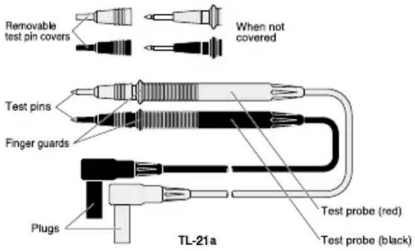
- Be sure to use the specified type of test leads.
- Never attempt repair or modification, except for battery and fuse replacement.
- Inspect the meter at least once a year.
- This meter is for indoor use only.

CAUTION
-
Correct measurement may not be performed when using the meter in the ferromagnetic / intense electric field such as places near a transformer, a high-current circuit, and a radio.
-
The meter may malfunction or correct measurement may not be performed when measuring special waveform such as that of the inverter circuit.
1-3 Overload Protection
The maximum rated input value and overload protection have been established for the input terminals of each function.
| Function Input | Terminal | Max. Rated Input Value | Max. Overload Protection Input Value |
| V·Hz | V/Hz/Hz and COM | DC·AC 600 V | DC·AC 600 V |
| Ω / → / ·) · → | Ω/→/·) | ||
| μA | μAmA and COM | Do not input a voltage or current. | 0.5 A/250 V fuseBreaking capacity 1.5 kA |
| mA | DC·AC 400 mADo not input a voltage. |
[2] APPLICATIONS AND FEATURES
2-1 Applications
This is a digital multimeter designed for measurement of low-voltage circuits. This meter is useful for measuring / analyzing circuits of small communication devices, home electric appliances and batteries.
2-2 Features
- The current terminal is protected with a safety cap.
- Easy-to-read display showing Eye-friendly large size LCD.
- Frequency measurement and capacitance measurement functions provided.
- Easy-to-hold design.
- Test probes can be held on the body.
- Double molding with outside made of elastic elastomer material.
[3] NAMES OF COMPONENT UNITS
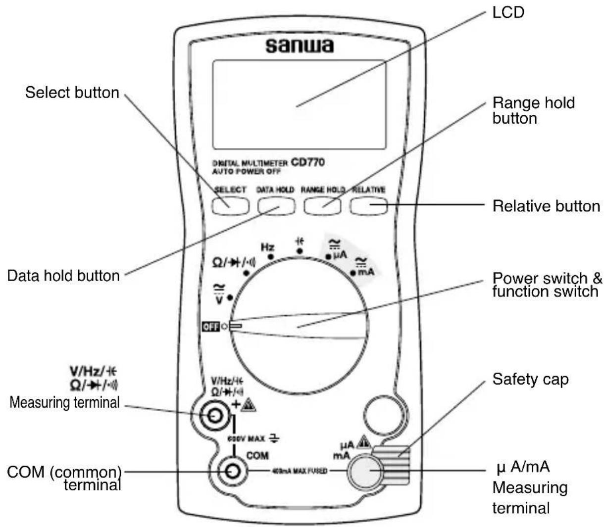
3- 1 Meter
3- 2 Test Leads
3-2 Display
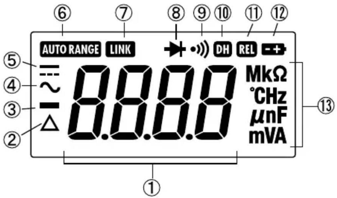
| 1 | Indication of numerical value. |
| 2 | Indication of relative mode operation. |
| 3 | Indication of negative sign of numerical data. |
| 4 | Indication of AC measuring function operation. |
| 5 | Indication of DC measuring function operation. |
| 6 | Indication of auto range mode operation. |
| 7 | Not used with this meter. |
| 8 | Indication of diode test function operation. |
| 9 | Indication of continuity check function operation. |
| 10 | Indication of data hold mode operation. |
| 11 | Indication of relative mode operation. |
| 12 | Indication of battery low warning. |
| 13 | Indication of units of measurement. |
[4] DESCRIPTION OF FUNCTIONS
4-1 Power Switch & Function Switch
Turn this switch to turn on and off the power and select a measuring function.
4-2 Measuring Function Selection: SELECT
When the SELECT button is pressed, the functions change as follows:
•V position: DC voltage (==) AC voltage ( )\~DC voltage ( ) =
• Ω /→+ /•• position: Resistance measurement (Ω) → diode test (••) → continuity check (••) -resistance measurement ( )Ω
- A position: DC current (==) AC current ( )\~DC current ( ) =
• mA position: DC current ( = ) AC current ( ) \~DC current ( ) =
4-3 Data Hold: DATA HOLD
When the DATA HOLD button is pressed, the value indicated will be held. ("DH" will appear on the display.) The indicated value will not change if the measurement input fluctuates.
When this button is pressed again, the hold status will be canceled and the meter will return to the measurement mode. ("DH" will disappear from the display.)
Remarks:
The DATA HOLD button does not work with the Hz function.
4-4 Range Hold: RANGE HOLD
When the RANGE HOLD button is pressed, the meter will be set in the manual mode and the range will be fixed. (“AUTO RANGE” will disappear from the display.) In the manual mode, each time this button is pressed, the range changes. While checking the unit and decimal point on the display, select the best range.
To return to the auto range, hold this button pressed for 1 second or longer. (“AUTO RANGE” will appear on the display.)
Remarks:
The RANGE HOLD button does not work with the (Hz), (→), (•) and (+) functions.
4-5 Relative Measurement: RELATIVE
When the RELATIVE button is pressed, REL and will light and the input value when the button was pressed will become 0 as the reference. To cancel it, press the button again.
Example: Display after pressing the button at DC 30.00 V input
| Actual Input Value Value in Display | |
| DC 0.00 VDC 30.00 V | |
| DC 5.00 VDC 35.00 V | |
| DC 25.00 V DC -5.00 V | |
Remarks:
This mode cannot be used with the Hz function. When a function other than ( ± ) is used, the range is fixed during relative measurement.
4-6 Auto Power Off
If no switch or button is operated for Approx. 30 minutes after power on, the power will automatically be turned off and the display will become blank.
To reset the meter, press any button or remove the object to measure from the DMM and set the function switch to OFF. Set the function switch again according to the measurement and connect the object to measure.
To cancel this function, turn on the power of meter while holding the SELECT button pressed.
4-7 Battery Low Warning Indication
When the built-in batteries have been discharged and the voltage has dropped to below Approx. 2.4 V, “ ” mark will appear in the display. When this mark flickers or lights, replace both two batteries with new ones.
[5] MEASURING PROCEDURE
![Sanwa CD770 - [5] MEASURING PROCEDURE - 1](/content/2026/05/851894/images/fa86d0861d793f038d35c2fce554b2c69f9a6aad706afdb4cdb9370ac364f1d1.jpg)
WARNING
- Do not apply an input signal exceeding the maximum rated input of each function.
- During measurement, do not change the function switch.
- During measurement, do not touch the test pin side of the flange of the test lead.
- When measurement has been finished, remove the test pins from the object measured and return the function switch to the OFF position.
5-1 Start-up Inspection

CAUTION
- Be sure that the battery low warning mark is not flickering or lit, when the meter is turned on. If it is flickering or lit, replace the batteries with new ones.
- Do not use the meter if the meter or test lead is damaged or broken.
- Make sure the test leads are not cut and the fuse has not blown.
Always conduct the start-up inspection to ensure safety. (Inspection by the continuity check.)
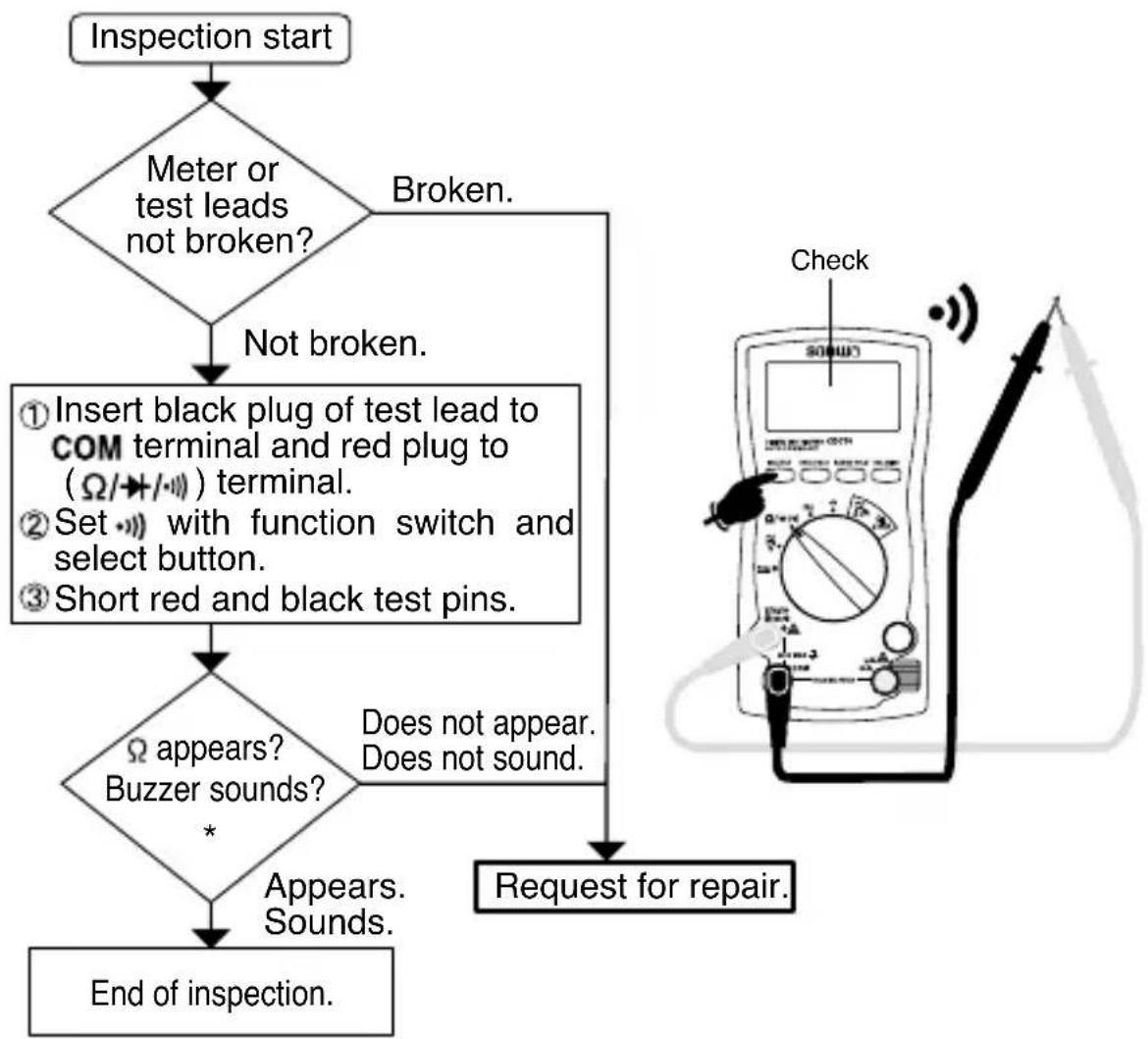
flowchart
graph TD
    A["Inspection start"] --> B{Meter or test leads not broken?}
    B -->|Not broken.| C["① Insert black plug of test lead to COM terminal and red plug to (Ω/→/→) terminal.<br>② Set → with function switch and select button.<br>③ Short red and black test pins."]
    C --> D{Ω appears? Buzzer sounds? *}
    D -->|Does not appear. Does not sound.| E["Request for repair."]
    D -->|Appears. Sounds.| F["End of inspection."]
    E --> G["Check"]
* If nothing appears on the display, the batteries might have been discharged completely.
5-2 Voltage Measurement (v)
| Function | Max. Rated Input | Range |
| DCV | DC 600 V | 400.0 mV, 4.000 V, 40.00 V, 400.0 V, 600 V |
| ACV | AC 600 V | 4.000 V, 40.00 V, 400.0 V, 600 V |
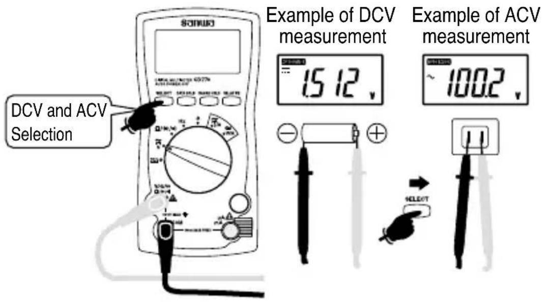
Remarks:
This meter's AC detection method is the average value method. It indicates an average value of voltage or current in the positive half cycle. No error will occur in measurement of waveforms when the input waveform is sinusoidal wave with no distortion. However, if the input waveform is distorted sinusoidal wave or non-sinusoidal wave, an error will occur.
- The indication may fluctuate when the test leads are released. It is not a failure.
• The AC 400.0 mV range can be selected with the RANGE HOLD button, but the accuracy is not guaranteed. - In the AC 4.000 V range, when the measuring terminals are shorted, 7 counts maximum may remain indicated.
• The accuracy guarantee frequency range of ACV measurement is 40 Hz to 400 Hz.
If the frequency is above 1 kHz, measurement is not possible.
- It may malfunction when measuring voltage in the inverter circuit.
5-3 Resistance Measurement ( ) Diode Test ( ➡ Continuity Check ( )
WARNING
Never apply a voltage to the measuring terminals.
5-3-1 Resistance measurement (Ω)
| Function | Max. Rated Input | Range |
| Ω | 40.00 MΩ | 400.0 Ω, 4.000 kΩ, 40.00 kΩ, 400.0 kΩ, 4.000 MΩ, 40.00 MΩ |
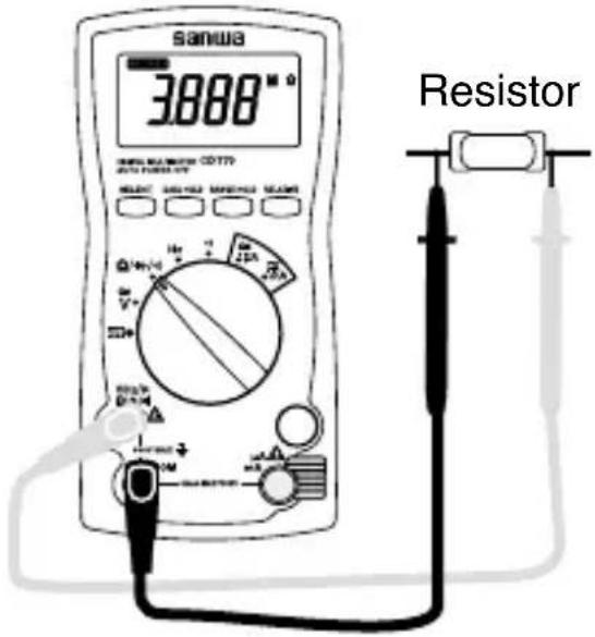
Caution:
If measurement is affected by noises, shield the object to measure with COM potential. If measurement is conducted with a finger touching the test pins, an error will occur due to influence of resistance of the human body. The open voltage between the measuring terminals is approx. 0.4 VDC.
5-3-2 Diode test (▶)
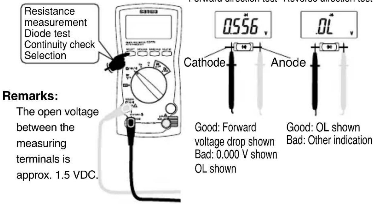
Forward direction test Reverse direction test
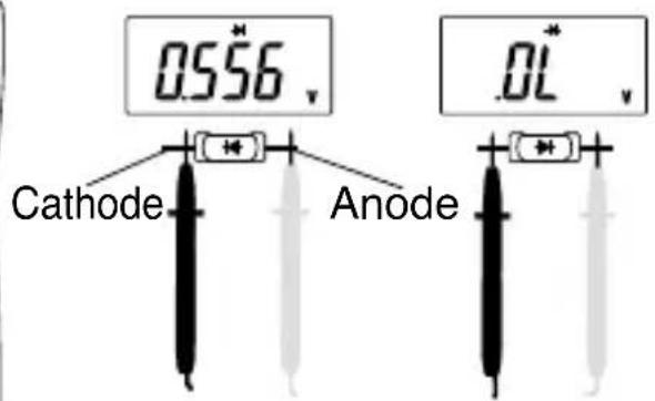
Good: Forward voltage drop shown Bad: 0.000 V shown OL shown
Good: OL shown
Bad: Other indication
5-3-3 Continuity check (·)
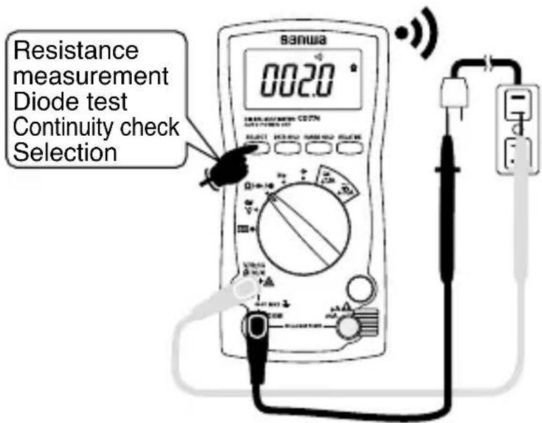
Remarks:
Continuity buzzer sound range: 0 Ω \~ 85 Ω (±45 Ω)
5-4 Frequency Measurement (Hz)

CAUTION
Never use the meter for measuring frequencies to ground as the earth leakage breaker may trip.
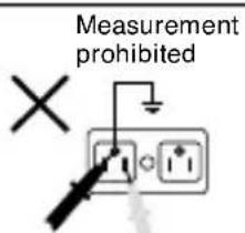
| Function | Max. Rated Input | Range |
| Hz | 100.0 kHz(≤ 600 Vrms) | 5.000 Hz, 50.00 Hz, 500.0 Hz, 5.000 kHz, 50.00 kHz, 100.0 kHz (Auto range only) |
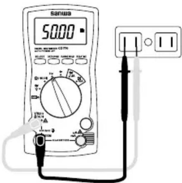
Remarks:
- Because the Hz function uses input resistance as low as approx 2 kΩ, adalarge amount of current will flow during measurement. Never use the meter for measuring circuits or devices having a small current capacity.
Remarks:
- Input sensitivity: 3 Vrms or over.
- Zero cross (+ potential → - potential → + potential) frequencies can be measured. Frequencies of + potential only or – potential only such as logic pulses cannot be measured.
- Frequencies less than 1 Hz cannot be measured.
- When the Hz function is used, the data hold and relative functions cannot be used.
5-5 Capacitance Measurement ( ± )

WARNING
Never apply a voltage to the measuring terminals.

CAUTION
- Remove electric charge in the capacitor prior to measurement.
- Because this meter applies a current to the capacitor to measure, it is not suitable for measurement of electrolytic capacitors having a large leak current as a large error will occur.
- For capacitors having large capacitance, measurement takes a longer time.
| Function | Max. Rated Input | Range |
| CAP ( ≠) 100 | 0.0 μF | 50.00 nF, 500.0 nF, 5.000 μF, 50.00 μF, 100.0 μF (Auto range) |
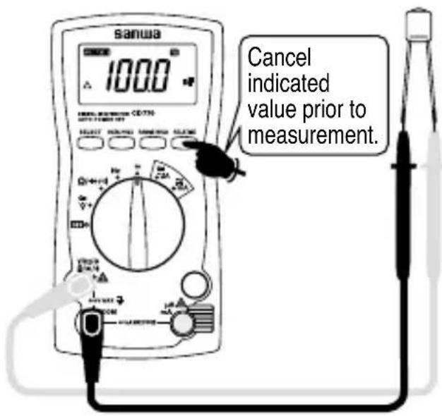
Remarks:
- For capacitance measurement, press the RELATIVE button to cancel the indicated value (00.00 nF) before connecting a capacitor.
- Only the auto range is available for the capacitance measuring function.
- The indication may not become stable due to influence of surrounding noises or stray capacitance of the test leads.
5-6 Current Measurement ( A/mA)

WARNING
- Never apply a voltage to the measuring terminals.
- Never apply an input exceeding the maximum rated current.
- Be sure to connect the meter in series via a load.
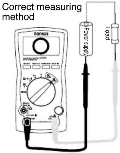
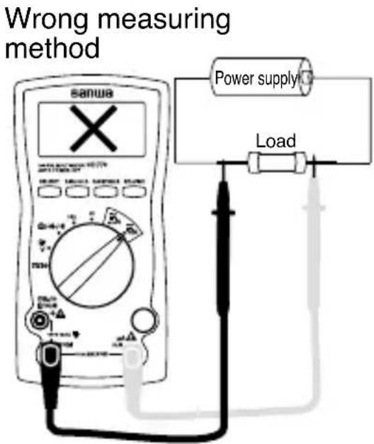

CAUTION
Be sure that the built-in fuse has not blown.
| Function Max. | Rated Input Range | |
| DC/AC μA 4000 | μA 400.0 μA, 4000 μA | |
| DC/AC mA 400 | mA 40.00 mA, 400.0 | mA |
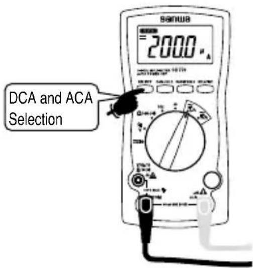
Remarks:
- In current measurement, the internal resistance of the current range is placed in series and the current drops by this resistance. Accordingly, its influence becomes larger in low-resistance circuits.
- The AC accuracy guarantee frequency range is from 40 Hz to 400 Hz.
- Current range: Auto range for 400.0 A \~ 4000 A and 40.00 mA \~ 400.0 mA. The range can be fixed by the RANGE HOLD button.
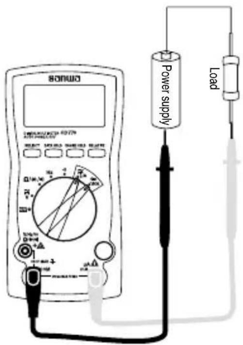
μA · mA measurement
| Function | Input Terminal | Built-in Fuse |
| μA | μA and com | 0.5 A/250 VFuse |
| mA | Breaking capacity1.5 kA |
- If the indication will change little when an input signal is applied or a current value which is significantly smaller than the expected value is indicated, possible causes are the input terminals, incorrect setting of the function switch, or blown fuse. Check these places.
[6] MAINTENANCE
![Sanwa CD770 - [6] MAINTENANCE - 1](/content/2026/05/851894/images/c86690bb3fce5ddeb1cf64e745054bdbc4b1618fc59e2eaafef3d6d07f18ba99.jpg)
WARNING
- The following instructions are very important for safety.
Read this manual thoroughly to ensure correct maintenance. - Calibrate and inspect the meter at least once a year to ensure safety and maintain its accuracy.
6-1 Maintenance and Inspection
1) Appearance: Is the meter not damaged due to falling or other cause?
2) Test leads:
- Are the core wires not exposed from the test leads?
- Is the plug when inserted to the input terminal not loose?
If any of the above problems exists, stop using the meter and request for repair.
6-2 Calibration and Inspection
For more information, please contact Sanwa's authorized agent / distributors. service provider, listed in our website.
See section 7-3.
6-3 Storage

CAUTION
- The panel and case are not resistant to volatile solvent and must not be cleaned with thinner or alcohol.
- The panel and case are not resistant to heat. Do not place the meter near heat-generating devices.
- Do not store the meter in a place where it may be subjected to vibration or where it may fall.
- Do not store the meter in places under direct sunlight, or hot, cold or humid places or places where condensation is anticipated.
- If the meter will not be used for a long time, remove the batteries.
6-4 Battery and Fuse Replacement Batteries when the meter is shipped:
A battery for monitoring has been installed prior to shipment from the factory. It may be discharged before the expiration of the described battery life.
*The battery for monitoring is a battery used to check the functions and performance of the product.

WARNING
-
To avoid electric shock, do not remove the rear case with an input being applied to the measuring terminals. Also, before starting replacement, make sure the power of the meter is OFF.
-
Be sure to use the replacement fuse of the same rating. Never use a substitute for the fuse nor short the meter.
6-4-1 Battery replacement
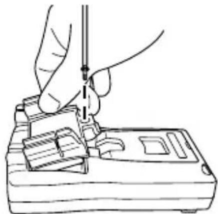
①Remove the fixing screw of the battery holder with a screwdriver.
②Replace both two batteries in the battery holder with new ones. (Pay attention to their polarities.)
③ Set and secure the battery holder with the fixing screw as before.
natural_image
Line drawing of a hand using a tool to adjust or install electronic components (no text or symbols visible)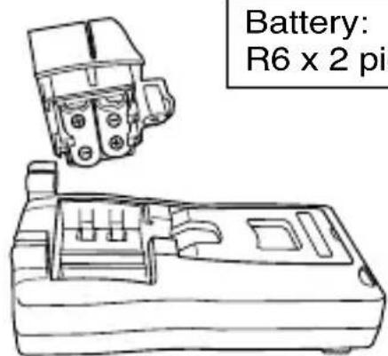
Battery: R6 x 2 pieces
6-4-2 Fuse replacement
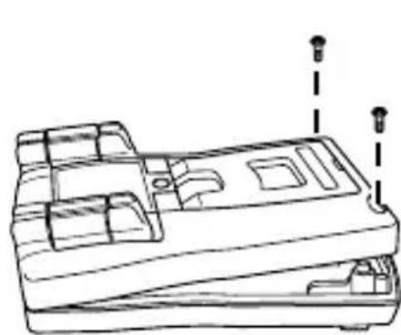
①Remove the screws of the body rear case with a screwdriver.
②Take out the fuse and replace it with a new one.
③ Secure the rear case with the screws as before.
natural_image
Technical line drawing of a mechanical component with mounting holes and internal compartments (no text or symbols)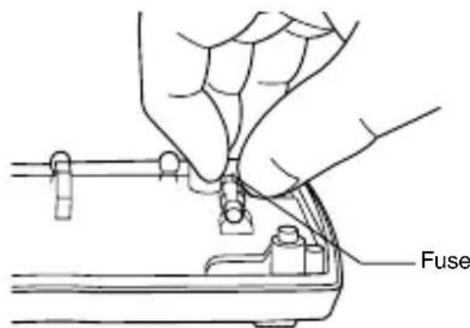
Fuse rating: 0.5 A/250 V (ø5 x 20 mm, Breaking capacity1.5 kA)
* Spare fuse storage is provided at the bottom of the rear case.
[7] After-Sale Service
7-1 Warranty and Provision
Sanwa offers comprehensive warranty services to its end-users and to its product resellers. Under Sanwa's general warranty policy, each instrument is warranted to be free from defects in workmanship or material under normal use for the period of one (1) year from the date of purchase.
This warranty policy is valid within the country of purchase only, and applied only to the product purchased from Sanwa authorized agent or distributor.
Sanwa reserves the right to inspect all warranty claims to determine the extent to which the warranty policy shall apply. This warranty shall not apply to disposables batteries, or any product or parts, which have been subject to one of the following causes:
- A failure due to improper handling or use that deviates from the instruction manual.
- A failure due to inadequate repair or modification by people other than Sanwa service personnel.
- A failure due to causes not attributable to this product such as fire, flood and other natural disaster.
- Non-operation due to a discharged battery.
- A failure or damage due to transportation, relocation or dropping after the purchase.
7-2 Repair
Customers are asked to provide the following information when requesting services:
- Description of problem
- Description of product configuration
- Model Number
- Product Serial Number
- Proof of Date-of-Purchase
-
Where you purchased the product
-
Customer name, address, and contact information
Please contact Sanwa authorized agent / distributor / service provider, listed in our website, in your country with above information. An instrument sent to Sanwa / agent / distributor without above information will be returned to the customer.
Note:
1) Prior to requesting repair, please check the following: Capacity of the built-in battery, polarity of installation and discontinuity of the test leads.
2) Repair during the warranty period: The failed meter will be repaired in accordance with the conditions stipulated in 7-1 Warranty and Provision.
3) Repair after the warranty period has expired: In some cases, repair and transportation cost may become higher than the price of the product. Please contact Sanwa authorized agent / service provider in advance.
The minimum retention period of service functional parts is 6 years after the discontinuation of manufacture. This retention period is the repair warranty period. Please note, however, if such functional parts become unavailable for reasons of discontinuation of manufacture, etc., the retention period may become shorter accordingly.
4) Precautions when sending the product to be repaired To ensure the safety of the product during transportation, place the product in a box that is larger than the product 5 times or more in volume and fill cushion materials fully and then clearly mark “Repair Product Enclosed” on the box surface. The cost of sending and returning the product shall be borne by the customer.
7-3 SANWA web site
http://www.sanwa-meter.co.jp
E-mail: exp_sales@sanwa-meter.co.jp
[8] SPECIFICATIONS
8-1 General Specifications
| Operation method | Δ-×method |
| AC measuring method | Average value method |
| LCD | 4000 counts |
| Sampling rate | Approx. 3 times/sec. |
| Range selection | Auto and Manual (Some with Manual only or Auto only) |
| Over-range indication | “OL” shown in numerical part. (600 V DC/AC excluded.) |
| Polarity indication automatic selection | “-” indicated only when negative input. |
| Battery low warning | Battery (→) mark lights or flickers at approx. 2.4 V or below. |
| Environmental condition | Altitude 2000 m or below, pollution degree II. |
| Operating temperature / humidity | 5 °C to 40 °C and humidity range as follows. No condensation allowed. At 5 °C to 31 °C, 80 % RH(max). At 31 °C to 40 °C, linear drop from 80 % RH to 50 % RH. |
| Storage temperature / humidity | -10 °C ~ 40 °C, 80 %RH max., no condensation 40 °C ~ 50 °C, 70 %RH max., no condensation (When the meter will not be used for a long time, remove the batteries before storage.) |
| Power supply | SUM-3 (R6P), 2 pieces |
| Battery life | About 400 hours continuously at DCV. (Auto power off canceled) |
| Auto power off | Power off about 30 minutes after no operation. |
| Fuse | 0.5 A/250 V, Breaking capacity1.5 kA |
| Dimensions | 166(L)W 82( ) x 44( ) mm (Projections not included) |
| Mass | Approx. 340 g (batteries included) |
| Power consumption | Typical 4.5 mW (at DCV) |
| Standard accessories included | Test lead (TL-21a), Instruction manual |
| Optional accessories | Alligator clip: CL-14, CL-13a, CL-15a, CL-DG3a, TL-9IC Clamp probe: CL-22AD, CL-33DC, CL3000 High voltage probe: HV-60 Carrying case: C-77, C-77H |
8-2 Measuring Range and Accuracy
Temperature: 23±5 °C, humidity: 80 % RH max. (no condensation), voltage 2.4 V or above.
rdg (reading): Read value, dgt (digit): Number of counts of last digit
DCV
| Range Accuracy Input Resistance | Remarks | ||
| 400.0 mV | ±(0.5 %rdg+2dgt) | ≥ Approx. 100 MΩ | |
| 4.000 V | ±(0.9 %rdg+2dgt) | Approx. 11 MΩ | |
| 40.00 V | Approx. 10 MΩ | ||
| 400.0 V | |||
| 600 V | |||
ACV
| Range Accuracy Input Resistance | Remarks | ||
| 4.000 V | ±(1.2 %rdg+7dgt) | Approx. 11 MΩ | · Frequency range: 40 Hz ~ 400 Hz (sinusoidal wave)· If the frequency is above 1 kHz, measurement is not possible.· If may malfunction when measuring voltage in the inverter circuit. |
| 40.00 V | Approx. 10 MΩ | ||
| 400.0 V | |||
| 600 V | |||
Resistance
| Range | Accuracy | Remarks |
| 400.0 Ω | ±(1.2 %rdg+5dgt) | · Open circuit voltage: Approx. 0.4 VDC· The measuring current varies depending on resistance of resistors to measure. |
| 4.000 kΩ | ||
| 40.00 kΩ | ||
| 400.0 kΩ | ||
| 4.000 MΩ | ±(2.0 %rdg+3dgt) | |
| 40.00 MΩ | ±(3.0 %rdg+3dgt) |
Diode test
Open circuit voltage: Approx. 1.5 VDC
Continuity check
Continuity buzzer sound range: 0 Ω \~ 85 Ω (±45 Ω)
Open circuit voltage: Approx. 0.4 VDC
Frequency
| skrameRycaruccAegnaR | ||
| 5.000 Hz | ±(0.3 %rdg+3dgt) | · Auto range only.· The data hold and relative functions cannot be used.· Sensitivity: 3 Vrms or over.· Frequency less than 1 Hz cannot be measured.· Input resistance Approx. 2 kΩBecause the input resistance is as low as approx. 2 kΩ, a large amount of current will flow during measurement. Never use the meter for measuring circuits or devices having a small current capacity.Never use the meter for measuring frequencies to ground as the earth leakage breaker may trip. |
| 50.00 Hz | ||
| 500.0 Hz | ||
| 5.000 kHz | ||
| 50.00 kHz | ||
| 100.0 kHz |
Capacitance
| skrameRycaruccAegnaR | ||
| 50.00 nF | ±(5.0 %rdg+10dgt) | · Accuracy after canceling the indicated value by the relative function. · Auto range only |
| 500.0 nF | ||
| 5.000 μF | ||
| 50.00 μF | ||
| 100.0 μF |
DCA
| Range Accuracy Input Resistance | Remarks | ||
| 400.0 μA | ±(1.4 %rdg+3dgt) | Approx. 100 Ω | · The input resistance excludes the fuse resistance. |
| 4000 μA | |||
| 40.00 mA | Approx. 1 Ω | ||
| 400.0 mA | |||
ACA
| Range Accuracy Input Resistance | Remarks | ||
| 400.0 μA | ±(1.8 %rdg+5dgt) | Approx. 100 Ω | · Accuracy guarantee frequency range: 40 Hz ~ 400 Hz (sinusoidal wave) · The input resistance excludes the fuse resistance. |
| 4000 μA | |||
| 40.00 mA | Approx. 1 Ω | ||
| 400.0 mA | |||
* Accurate measurement may not be possible in places near a transformer, large-current line, etc. where a strong magnetic field is present or near radio equipment, etc. that generates a strong electric field.
Accuracy calculation
Example: DCV function
True value: 100 mV
Range accuracy: 400 mV range ...±(0.5 %rdg+2dgt)
Error: ±(100.0 mV x 0.5 % + 2dgt) = ±0.7 mV
Indicated value: 100.0 mV ± 0.7 mV (in a range of 99.3 mV and 100.7 mV)
The product specifications described in this manual and its appearance are subject to change without notice for improvement or other reasons.
sanwa®
三和電気計器株式会社
- 【1】 SAFETY PRECAUTIONS – Before use, read the following safety precautions.-
- 【2】 APPLICATIONS AND FEATURES
- [7] After-Sale Service
- 【8】 SPECIFICATIONS
- [1] SAFETY PRECAUTIONS
- 1-1 Explanation of Warning Symbols
- 1-2 Warning Messages for Safe Use
- WARNING
- CAUTION
- 1-3 Overload Protection
- [2] APPLICATIONS AND FEATURES
- 2-1 Applications
- 2-2 Features
- [3] NAMES OF COMPONENT UNITS
- [4] DESCRIPTION OF FUNCTIONS
- 4-1 Power Switch & Function Switch
- 4-2 Measuring Function Selection: SELECT
- 4-3 Data Hold: DATA HOLD
- Remarks:
- 4-4 Range Hold: RANGE HOLD
- 4-5 Relative Measurement: RELATIVE
- 4-6 Auto Power Off
- 4-7 Battery Low Warning Indication
- [5] MEASURING PROCEDURE
- 5-1 Start-up Inspection
- 5-2 Voltage Measurement (v)
- 5-3 Resistance Measurement ( ) Diode Test ( ➡ Continuity Check ( )
- Caution:
- 5-3-3 Continuity check (·)
- 5-4 Frequency Measurement (Hz)
- 5-5 Capacitance Measurement ( ± )
- 5-6 Current Measurement ( A/mA)
- [6] MAINTENANCE
- 6-1 Maintenance and Inspection
- 6-2 Calibration and Inspection
- 6-3 Storage
- 6-4 Battery and Fuse Replacement Batteries when the meter is shipped:
- 6-4-1 Battery replacement
- 6-4-2 Fuse replacement
- 7-1 Warranty and Provision
- 7-2 Repair
- Note:
- 7-3 SANWA web site
- [8] SPECIFICATIONS
- 8-2 Measuring Range and Accuracy
- Diode test
- Continuity check
- Accuracy calculation
- sanwa®
- 三和電気計器株式会社
Brand : Sanwa
Model : CD770
Category : Multimeter