
3RW4027-1BB15 - Uncategorized SIEMENS - Free user manual and instructions
Find the device manual for free 3RW4027-1BB15 SIEMENS in PDF.


| Product Type | Soft Starter |
| Series | SIRIUS 3RW40 |
| Rated Operational Voltage | 200-600 V AC |
| Rated Control Supply Voltage | 24 V AC/DC |
| Rated Operational Current (Ie) at 40 °C | 27 A |
| Motor Power at 400 V | 18.5 kW |
| Starting Method | Voltage ramp with current limiting |
| Stop Modes | Soft stop and natural stop |
| Protection Features | Motor overload protection, intrinsic device protection, optional thermistor motor protection |
| Dimensions (W x H x D) | 45 mm x 100 mm x 130 mm |
| Weight (approx.) | 0.5 kg |
| Operating Temperature | -25 °C to +60 °C |
| Mounting | Panel mounting, side-by-side assembly possible |
| Terminal Type | Screw terminals |
| Standards | IEC/EN 60947-4-2 |
| Communication | None |
| Accessories | Optional fan, link modules, terminal covers |
| Maintenance | Periodic inspection of connections and cooling |
| Safety | Follow five safety rules: isolate, secure, verify, ground, cover |
| Spare Parts | Fan, terminal covers, sealing covers |
Frequently Asked Questions - 3RW4027-1BB15 SIEMENS
User questions about 3RW4027-1BB15 SIEMENS
0 question about this device. Answer the ones you know or ask your own.
Ask a new question about this device
Download the instructions for your Uncategorized in PDF format for free! Find your manual 3RW4027-1BB15 - SIEMENS and take your electronic device back in hand. On this page are published all the documents necessary for the use of your device. 3RW4027-1BB15 by SIEMENS.
USER MANUAL 3RW4027-1BB15 SIEMENS
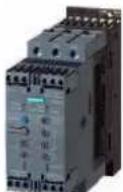
natural_image
Four industrial electrical contactors with visible terminal labels and control buttons (no readable text or symbols)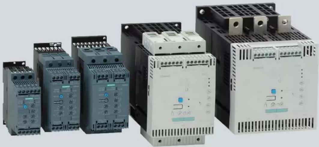
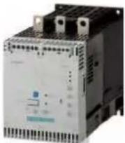
natural_image
Collection of industrial electrical contactors with no visible text or symbols on their surfacesIndustrial Controls
Answers for industry.
SIEMENS
SIEMENS
Industrial Controls
Soft starters SIRIUS 3RW30 / 3RW40
Manual
| Introduction | 1 |
| Safety information | 2 |
| Product description | 3 |
| Product combinations | 4 |
| Functions | 5 |
| Application planning | 6 |
| Installation | 7 |
| Installation / mounting | 8 |
| Connecting | 9 |
| Operation | 10 |
| Configuration | 11 |
| Commissioning | 12 |
| Technical data | 13 |
| Dimension drawings | 14 |
| Typical circuit diagrams | 15 |
| Accessories | 16 |
| Appendix | A |
Legal information
Warning notice system
This manual contains notices you have to observe in order to ensure your personal safety, as well as to prevent damage to property. The notices referring to your personal safety are highlighted in the manual by a safety alert symbol, notices referring only to property damage have no safety alert symbol. These notices shown below are graded according to the degree of danger.
| ⚠️ DANGER |
| indicates that death or severe personal injury will result if proper precautions are not taken. |
| ⚠️ WARNING |
| indicates that death or severe personal injury may result if proper precautions are not taken. |
| ⚠️ CAUTION |
| with a safety alert symbol, indicates that minor personal injury can result if proper precautions are not taken. |
| CAUTION |
| without a safety alert symbol, indicates that property damage can result if proper precautions are not taken. |
| NOTICE |
| indicates that an unintended result or situation can occur if the corresponding information is not taken into account. |
| If more than one degree of danger is present, the warning notice representing the highest degree of danger will be used. A notice warning of injury to persons with a safety alert symbol may also include a warning relating to property damage. |
Qualified Personnel
The product/system described in this documentation may be operated only by personnel qualified for the specific task in accordance with the relevant documentation for the specific task, in particular its warning notices and safety instructions. Qualified personnel are those who, based on their training and experience, are capable of identifying risks and avoiding potential hazards when working with these products/systems.
Proper use of Siemens products
Note the following:
| WARNING |
| Siemens products may only be used for the applications described in the catalog and in the relevant technical documentation. If products and components from other manufacturers are used, these must be recommended or approved by Siemens. Proper transport, storage, installation, assembly, commissioning, operation and maintenance are required to ensure that the products operate safely and without any problems. The permissible ambient conditions must be adhered to. The information in the relevant documentation must be observed. |
Trademarks
All names identified by ® are registered trademarks of the Siemens AG. The remaining trademarks in this publication may be trademarks whose use by third parties for their own purposes could violate the rights of the owner.
Disclaimer of Liability
We have reviewed the contents of this publication to ensure consistency with the hardware and software described. Since variance cannot be precluded entirely, we cannot guarantee full consistency. However, the information in this publication is reviewed regularly and any necessary corrections are included in subsequent editions.
Table of contents
1 Introduction 11
1.1 Important notes.... 11
2 Safety information 13
2.1 Before commencing work: Isolating the equipment from the supply system and ensuring that it cannot be reconnected.... 13
2.2 Five safety rules for work in or on electrical systems 13
3 Product description 15
3.1 Fields of application.... 15
3.2 Basic physical principles of a three-phase induction motor 15
3.2.1 Three-phase induction motor 15
3.3 Functional principle of the SIRIUS 3RW30 and 3RW40 soft starters.... 17
3.3.1 Method of operation of a two-phase controlled soft starter 20
3.3.2 Starting current asymmetry 21
3.3.3 Applications and use 22
3.4 Comparison of device functions 24
4 Product combinations 25
4.1 SIRIUS modular system 25
5 Functions 27
5.1 Start modes 27
5.1.1 Voltage ramp 27
5.1.2 Current limiting and ramp-up detection (3RW40 only) 29
5.2 Stop modes 30
5.2.1 Stop without load (3RW30 and 3RW40) 31
5.2.2 Soft stop (3RW40 only) 31
5.3 Motor protection / intrinsic device protection (3RW40 only) 32
5.3.1 Motor protection function 32
5.3.2 Intrinsic device protection (3RW40 only) 35
5.4 Functions of the RESET buttons 36
5.4.1 SIRIUS 3RW40 2, 3RW40 3, and 3RW40 4 soft starters .... 36
5.4.2 SIRIUS 3RW40 5 and 3RW40 7 soft starters 38
5.4.3 Other functions of the RESET button 39
5.5 Functions of the inputs 40
5.5.1 Start input (terminal 1) on 3RW30 and 3RW40 2 to 3RW40 4 40
5.5.2 Start input (terminal 3) on 3RW40 5 and 3RW40 7 40
5.5.3 Thermistor input / connection on 3RW40 2 to 3RW40 4 41
5.6 Functions of the outputs 41
5.6.1 3RW30: Output terminal 13 / 14 ON 41
5.6.2 3RW40: Output terminals 13 / 14 ON / RUN and 23 / 24 BYPASSED 42
5.6.3 3RW40: Group fault output at terminal 95 / 96 / 98 OVERLOAD / FAILURE 43
5.7 Diagnostics and fault signals 44
5.7.1 3RW30: LEDs and troubleshooting .... 44
5.7.2 3RW40: LEDs and troubleshooting .... 46
6 Application planning 51
6.1 Application examples.... 51
6.1.1 Roller conveyor application 51
6.1.2 Hydraulic pump application 52
7 Installation 53
7.1 Installing the soft starter.... 53
7.1.1 Unpacking 53
7.1.2 Permissible mounting position 53
7.1.3 Mounting dimensions, clearances, and assembly type 54
7.1.4 Assembly type: Standalone assembly, side-by-side assembly, direct mounting 55
7.1.5 Installation requirements 56
8 Installation / mounting 57
8.1 General information 57
8.2 Five safety rules for work in or on electrical systems 58
8.3 General feeder assembly (type of coordination 1).... 59
8.4 Soft starter with line contactor (type of coordination 1)....60
8.5 Soft starter assembly with type of coordination 2....61
8.6 Capacitors to improve the power factor 62
8.7 Maximum cable length.... 63
9 Connecting 65
9.1 Electrical connection.... 65
9.1.1 Control and auxiliary terminals 65
9.1.2 Main circuit connection 65
10 Operation 69
10.1 Operator controls, displays, and connections on the 3RW30....69
10.2 Operator controls, displays, and connections on the 3RW40....70
11 Configuration 73
11.1 Configuration in general.... 73
11.1.1 Configuration procedure 73
11.1.2 Selecting the optimum soft starter 74
11.2 Startup class 76
11.2.1 Application examples for normal starting (CLASS 10) with 3RW30 and 3RW40 ....77
11.2.2 Application examples for heavy-duty starting (CLASS 20): 3RW40 only 78
11.3 ON time and switching frequency.... 79
11.4 Reducing the rated data 80
11.5 Installation altitude and ambient temperature.... 80
11.6 Calculating the permissible switching frequency 81
11.6.1 Table of permissible assembly combinations with switching frequency factors 81
11.6.2 Calculating the switching frequency (example) 84
11.7 Configuration aids.... 86
11.7.1 Online configurator 86
11.7.2 Win-Soft Starter selection and simulation software 86
11.7.3 Technical Assistance 86
11.7.4 SIRIUS soft starter training course (SD-SIRIUSO) 87
11.8 Order number system for the 3RW30.... 88
11.9 Order number system for the 3RW40....89
12 Commissioning 91
12.1 Before commencing work: Isolating the equipment from the supply system and ensuring that it cannot be reconnected.... 91
12.2 Commissioning the 3RW30 92
12.2.1 Commissioning procedure 92
12.2.2 Quick commissioning of the 3RW30 and optimization of the parameters 93
12.2.3 Setting the soft start function 94
12.2.4 Setting the starting voltage 95
12.2.5 Setting the ramp time 95
12.2.6 ON output 96
12.3 3RW30: LEDs and troubleshooting 97
12.4 Commissioning the 3RW40....98
12.4.1 Commissioning procedure 99
12.4.2 Quick commissioning of the 3RW40 and optimization of the parameters 100
12.4.3 Setting the soft start function 101
12.4.4 Setting the starting voltage 102
12.4.5 Setting the ramp time 102
12.4.6 Current limiting in conjunction with a starting voltage ramp and ramp-up detection 103
12.4.7 Setting the motor current 103
12.4.8 Setting the current limiting value 104
12.4.9 Ramp-up detection 104
12.5 Setting the soft stop function 105
12.5.1 Setting the ramp-down time 105
12.6 Setting the motor protection function.... 105
12.6.1 Setting the electronic motor overload protection 106
12.6.2 Motor current settings 107
12.6.3 Motor protection acc. to ATEX 107
12.7 Thermistor motor protection 108
12.8 Motor protection trip test.... 108
12.9 Functions of the outputs 109
12.9.1 Functions of the BYPASSED and ON / RUN outputs 109
12.9.2 Parameterizing the 3RW40 outputs 110
12.9.3 Function of the FAILURE / OVERLOAD output 112
12.10 RESET MODE and functions of the RESET / TEST button 113
12.10.1 SIRIUS 3RW40 2. to 3RW40 4. soft starters 113
12.10.2 SIRIUS 3RW40 5. to 3RW40 7. soft starters 115
12.11 3RW40: LEDs and troubleshooting 117
13 Technical data 121
13.1 3RW30.... 121
13.1.1 Overview 121
13.1.2 Selection and ordering data for standard applications and normal starting 122
13.1.3 3RW30.-BB.. control electronics 123
13.1.4 3RW30..-BB.. control times and parameters 123
13.1.5 3RW30.-BB.. power electronics 124
13.1.6 3RW30 13, 14, 16, 17, 18-.BB.. power electronics 124
13.1.7 3RW30 26, 27, 28-.BB.. power electronics 125
13.1.8 3RW30 36, 37, 38, 46, 47-.BB.. power electronics 125
13.1.9 3RW30 main conductor cross-sections 126
13.1.10 3RW30 auxiliary conductor cross-sections 127
13.1.11 Electromagnetic compatibility according to EN 60947-4-2 127
13.1.12 Recommended filters 128
13.1.13 Types of coordination 128
13.1.14 Fuseless version 129
13.1.15 Fused version (line protection only) 130
13.1.16 Fused version with SITOR 3NE1 fuses 131
13.1.17 Fused version with SITOR 3NE3/4/8 fuses 132
13.2 3RW40.... 134
13.2.1 Overview 134
13.2.2 Selection and ordering data for standard applications and normal starting (CLASS 10) ..... 135
13.2.3 Selection and ordering data for standard applications and normal starting (CLASS 10) (with thermistor motor protection evaluation) 137
13.2.4 Selection and ordering data for standard applications and normal starting (CLASS 10) ..... 139
13.2.5 Selection and ordering data for standard applications and heavy-duty starting (CLASS 20) .. 141
13.2.6 Selection and ordering data for standard applications and heavy-duty starting (CLASS 20) .. 143
13.2.7 3RW40 2., 3., 4. control electronics 145
13.2.8 3RW40 5., 7. control electronics 145
13.2.9 3RW40 2., 3., 4. control electronics 146
13.2.10 3RW40 5., 7. control electronics 146
13.2.11 3RW40 protection functions 147
13.2.12 3RW40 control times and parameters 147
13.2.13 3RW40 2. to 7. power electronics 148
13.2.14 3RW40 24, 26, 27, 28 power electronics 149
13.2.15 3RW40 36, 37, 38, 46, 47 power electronics 150
13.2.16 3RW40 55, 56, 73, 74, 75, 76 power electronics 151
13.2.17 3RW40 2., 3., 4. main conductor cross-sections 152
13.2.18 3RW40 5., 7. main conductor cross-sections 153
13.2.19 3RW40 .. auxiliary conductor cross-sections 154
13.2.20 Electromagnetic compatibility according to EN 60947-4-2 154
13.2.21 Recommended filters 155
13.2.22 Types of coordination 155
13.2.23 Fuseless version 156
13.2.24 Fused version (line protection only) 157
13.2.25 Fused version with SITOR 3NE1 fuses 158
13.2.26 Fused version with SITOR 3NE3/4/8 fuses 159
13.2.27 Motor protection tripping characteristics for 3RW40 (with symmetry) 161
13.2.28 Motor protection tripping characteristics for 3RW40 (with asymmetry) 161
13.3 Win-Soft Starter selection and simulation software 162
14 Dimension drawings 163
14.1 3RW30 for standard applications 163
14.2 3RW40 for standard applications 164
15 Typical circuit diagrams 167
15.1 Typical circuit for the optional thermistor motor protection evaluation.... 167
15.2 Control by pushbutton 168
15.2.1 Control of the 3RW30 by pushbutton 168
15.2.2 Control of the 3RW40 by pushbutton 169
15.3 Control by switch 170
15.3.1 Control of the 3RW30 by switch 170
15.3.2 Control of the 3RW40 by switch 171
15.4 Control in automatic mode.... 172
15.4.1 Control of the 3RW30 in automatic mode 172
15.4.2 Control of the 3RW40 in automatic mode 173
15.5 Control by PLC 175
15.5.1 Control of the 3RW30 with 24 V DC by PLC 175
15.5.2 Control of the 3RW40 by PLC 176
15.6 Control with an optional main / line contactor 177
15.6.1 Control of the 3RW30 with a main contactor 177
15.6.2 Control of the 3RW40 with a main contactor 178
15.7 Reversing circuit.... 180
15.7.1 3RW30 reversing circuit 180
15.7.2 3RW40 reversing circuit 181
15.8 Control of a magnetic parking brake.... 183
15.8.1 3RW30 motor with magnetic parking brake 183
15.8.2 3RW40 2 to 3RW40 4, control of a motor with a magnetic parking brake 184
15.8.3 3RW40 5 to 3RW40 7, control of a motor with a magnetic parking brake 185
15.9 Emergency stop.... 186
15.9.1 3RW30 emergency stop and 3TK2823 safety relay 186
15.9.2 3RW40 2 to 3RW40 4 emergency stop and 3TK2823 safety relay 187
15.9.3 3RW40 5 to 3RW40 7 emergency stop and 3TK2823 safety relay 189
15.10 3RW and contactor for emergency starting.... 191
15.10.1 3RW30 and contactor for emergency starting 191
15.10.2 3RW40 and contactor for emergency starting 192
15.11 Dahlander / multispeed motor 194
15.11.1 3RW30 and Dahlander motor starting 194
15.11.2 3RW40 2 to 3RW40 4 and Dahlander motor starting 195
15.11.3 3RW40 5 to 3RW40 7 and Dahlander motor starting 197
16 Accessories 199
16.1 Box terminal blocks for soft starters 199
16.2 Auxiliary conductor terminals.... 199
16.3 Covers for soft starters 199
16.4 Modules for RESET 200
16.5 Link modules to 3RV10 motor starter protectors 201
16.6 Link modules to 3RV20 motor starter protectors 201
16.7 Optional fan to increase the switching frequency (3RW40 2. to 3RW40 4.).... 202
16.8 Spare parts for fans (3RW40 5., 3RW40 7.).... 202
16.9 Operating instructions.... 202
A Appendix 203
A.1 Configuration data 203
A.2 Table of parameters used.... 205
A.3 Correction sheet 206
Introduction
1.1 Important notes
Purpose of the manual
This manual contains fundamental information and practical tips for using SIRIUS soft starters. The SIRIUS 3RW30 and 3RW40 soft starters are electronic motor control devices that facilitate optimal starting and stopping three-phase induction motors. The manual describes all of the functions of the SIRIUS 3RW30 and 3RW40 soft starters.
Target group
This manual is intended for any user involved in
- Commissioning
• Servicing and maintaining - Planning and configuring systems
Basic knowledge required
A general knowledge of the field of electrical engineering is required to understand this manual.
Scope of validity
The manual is valid for the SIRIUS 3RW30 and 3RW40 soft starters. It describes the components that are valid at the time of publication. SIEMENS reserves the right to include a Product Information for each new component, and for each component of a later version.
Standards and approvals
The SIRIUS 3RW30 and 3RW40 soft starters are based on the IEC/EN 60947-4-2 standard.
Disclaimer of liability
It is the responsibility of the manufacturer to ensure that a system or machine is functioning properly as a whole. SIEMENS AG, its regional offices, and associated companies (hereinafter referred to as "SIEMENS") cannot guarantee all the properties of a whole plant system or machine that has not been designed by SIEMENS.
Similarly, SIEMENS can assume no liability for recommendations that appear or are implied in the following description. No new guarantee, warranty, or liability claims beyond the scope of the SIEMENS general terms of supply are to be derived or inferred from the following description.
1.1 Important notes
Orientation aids
The manual contains various features supporting quick access to specific information:
- At the beginning of the manual you will find a table of contents.
- A comprehensive index at the end of the manual allows quick access to information on specific subjects.
Continuously updated information
Your regional contact for low-voltage switchgear with communications capability will be happy to help you with any queries you have regarding the soft starters. A list of contacts and the latest version of the manual are available on the Internet at (www.siemens.com/softstarte):
For all technical queries, please contact:
| Technical Assistance: | Phone: +49 (0) 911-895-5900 (8°° - 17°° CET) Fax: +49 (0) 911-895-5907e-mail: (mailto:technical-assistance@siemens.com)Internet: (www.siemens.com/lowvoltage/technical-assistance) |
Correction sheet
A correction sheet is included at the end of the manual. Please use it to record your suggestions for improvements, additions, and corrections, and return the sheet to us. This will help us to improve the next edition of the manual.
2.1 Before commencing work: Isolating the equipment from the supply system and ensuring that it cannot be reconnected.

DANGER
Hazardous voltage Will cause death or serious injury.
- Disconnect the system and all devices from the power supply before starting work.
- Secure against switching on again.
- Verify that the equipment is not live.
• Ground and short-circuit. - Erect barriers around or cover adjacent live parts.

DANGER
Hazardous voltage Will cause death or serious injury.
Qualified Personnel.
The equipment / system may only be commissioned and operated by qualified personnel. For the purpose of the safety information in these Operating Instructions, a "qualified person" is someone who is authorized to energize, ground, and tag equipment, systems, and circuits in accordance with established safety procedures.
2.2 Five safety rules for work in or on electrical systems
A set of rules, which are summarized in DIN VDE 0105 as the "five safety rules", are defined for work in or on electrical systems as a preventative measure against electrical accidents:
- Isolate
- Secure against switching on again
- Verify that the equipment is not live
- Ground and short-circuit
- Erect barriers around or cover adjacent live parts
These five safety rules must be applied in the above order prior to starting work on an electrical system. After completing the work, proceed in the reverse order.
It is assumed that every electrician is familiar with these rules.
2.2 Five safety rules for work in or on electrical systems
Explanations
- The isolating distances between live and deenergized parts of the system must vary according to the operating voltage that is applied.
"Isolate" refers to the all-pole disconnection of live parts.
All-pole disconnection can be achieved, e.g. by.: - Switching off the miniature circuit breaker
- Switching off the motor circuit breaker
- Unscrewing fusible links
-
Removing LV HRC fuses
-
The feeder must be secured against inadvertent restarting to ensure that it remains isolated for the duration of the work. This can be achieved, for instance, by securing the motor and miniature circuit breakers with lockable blocking elements in the disconnected state, either using a lock or by unscrewing the fuses.
-
The deenergized state of the equipment should be verified using suitable test equipment, e.g. a two-pole voltmeter. Single-pole test pins are not suitable for this purpose. The absence of power must be established for all poles, phase to phase, and phase to N/PE.
-
Grounding and short-circuiting are only mandatory if the system has a nominal voltage greater than 1 kV. In this case, the system should always be grounded first and then connected to the live parts to be short-circuited.
-
These parts should be covered, or barriers erected around them, to avoid accidental contact during the work with adjacent parts that are still live.
Product description
3.1 Fields of application
Soft starters are used to start three-phase induction motors with reduced torque and reduced starting current.
SIRIUS soft starter family
The SIEMENS SIRIUS soft starter family comprises three different versions with different functionalities and prices.
3RW30 and 3RW40
Simple or standard applications are covered by the SIRIUS 3RW30 and 3RW40 soft starters and are described in this manual.
3RW44
The SIRIUS 3RW44 soft starter is used if higher functionality is specified, e.g. communication over PROFIBUS or the availability of measuring and monitoring values, as well as for ultra-heavy-duty starting. The SIRIUS 3RW44 soft starter is described in a separate system manual.
Download from 3RW44 manual (http://support.automation.siemens.com/WW/
llisapi.dll?func=cslib.csinfo&lang=de&objid=21(72518&caller=view).
3.2 Basic physical principles of a three-phase induction motor
SIRIUS soft starters are used to reduce the current and torque of a three-phase induction motor during the startup process.
3.2.1 Three-phase induction motor
Fields of application
Three-phase induction motors are used in a wide range of applications in commerce, industry, and trade owing to their simple, robust design and their minimal maintenance.
Problem
If a three-phase induction motor is started directly, its typical current and torque characteristics can cause disturbances in the supply system and the load machine.
3.2 Basic physical principles of a three-phase induction motor
Starting current
Three-phase induction motors have a high direct starting current I_starting . Depending on the motor type, this current can be between three and fifteen times as high as the rated operational current. Seven or eight times the motor's rated current can be assumed as a typical value.
Disadvantage
This results in the following disadvantage:
- Higher load on the electrical supply system. The supply system must therefore be dimensioned for this higher power during the motor startup.
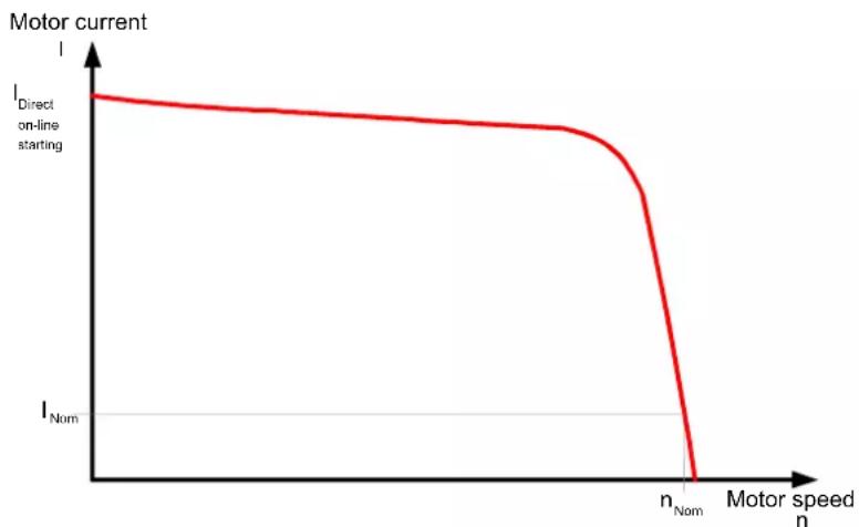
line
| Motor speed n | I_Direct on-line starting | | ------------- | ------------------------- | | 0 | I_Direct on-line starting | | n_Nom | I_Nom | | Motor speed n | I_Nom |Figure 3-1 Typical starting current characteristic of a three-phase induction motor
Starting torque
The starting torque and the breakdown torque can usually be assumed to be between two and four times the rated torque. From the point of view of the load machine, this means that the starting and acceleration forces exert a higher mechanical load on the machine and the product being conveyed compared to nominal operation.
Disadvantages
This results in the following disadvantages
- A higher load is placed on the machine's mechanical components
- The costs for replacing worn parts and maintaining the application are higher
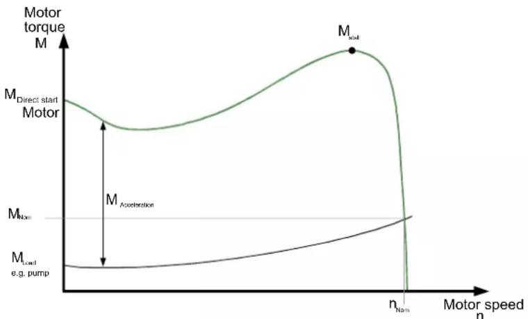
line
| Motor speed n | Motor torque M | Motor acceleration M_Acceleration | | ------------- | -------------- | --------------------------------- | | 0 | High | Low | | N | Medium | Medium | | N | Low | High |Figure 3-2 Typical starting torque characteristic of a three-phase induction motor
Remedy
The SIRIUS 3RW30 and 3RW40 electronic soft starters allow the current and torque characteristics during starting to be optimally adapted to the requirements of each application.
3.3 Functional principle of the SIRIUS 3RW30 and 3RW40 soft starters
The SIRIUS 3RW30 and 3RW40 soft starters have two antiparallel thyristors in two out of the three phases. One thyristor for the positive half-wave and one for the negative half-wave is provided in each phase (refer to Fig. "Phase angle control and schematic diagram of a two-phase controlled soft starter with integral bypass contacts"). The current in the third, uncontrolled phase is the sum of the currents in the controlled phases.
The rms value of the motor voltage is increased (from a settable starting voltage) to the rated motor voltage within a definable ramp-up time by means of the phase angle control.
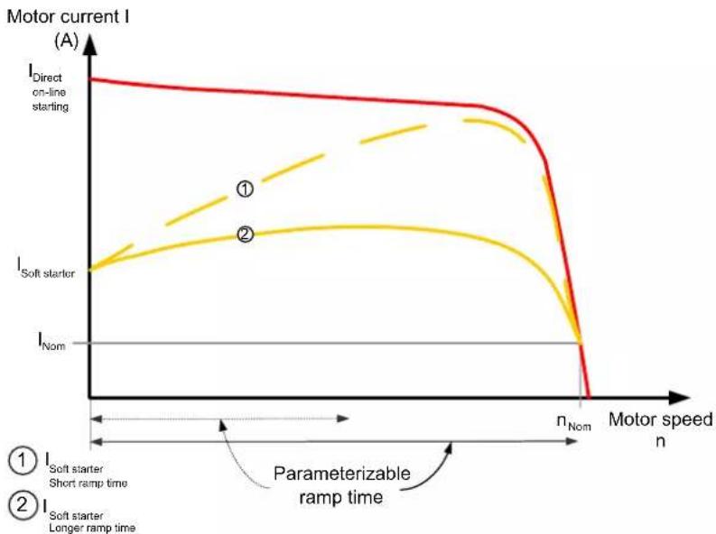
The motor current changes in proportion to the voltage applied to the motor. As a result, the starting current is reduced by the factor of this voltage.
There is a quadratic relationship between the torque and the voltage applied to the motor. As a result, the starting torque is reduced quadratically in relation to this voltage.
3.3 Functional principle of the SIRIUS 3RW30 and 3RW40 soft starters
Example
SIEMENS 1LG4253AA motor (55 kW)
Rated data at 400 V
P_e : 55 kW
I_e : 100 A
I_direct starting : Approx. 700 A
M_e :
355 Nm ; e.g.: M_e = 9.55 × 55 kW × 10001480 min^2
n_e : 1480 rpm
M_direct starting : Approx. 700 Nm
Set starting voltage: 50 % ( 12 of mains voltage)
=> I_starting 12 of direct starting current (approx. 350 A)
=> M_starting 14 of direct starting torque (approx. 175 Nm)
The diagrams below show the starting current and torque characteristics for a three-phase induction motor in combination with a soft starter:
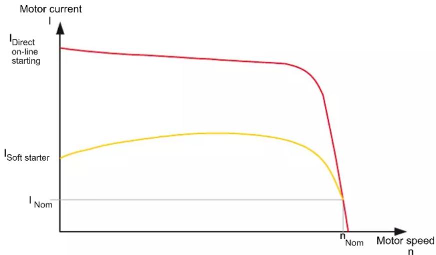
line
| Motor speed n | Direct on-line starting | Soft starter | | ------------- | ------------------------ | ------------ | | 0 | High | Low | | N | Low | Peak | | Nom | 0 | 0 |Figure 3-3 Reduced current characteristic of a three-phase induction motor during starting with a SIRIUS 3RW30 or 3RW40 soft starter
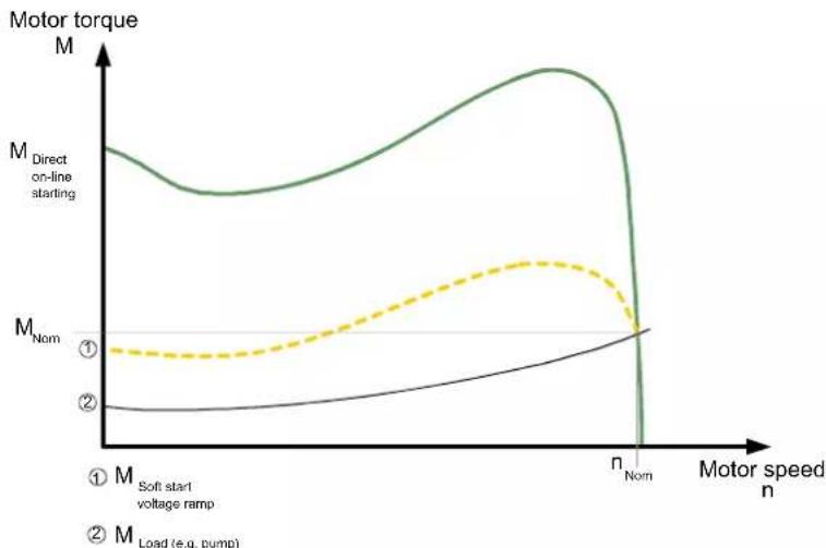
Figure 3-4 Reduced torque characteristic of a three-phase induction motor during starting with a SIRIUS 3RW30 or 3RW40 soft starter
Soft start /soft stop
This means that, since the motor voltage is controlled by the electronic soft starter during the startup process, the consumed starting current and the starting torque generated in the motor are also controlled.
The same principle is applied during the stop process. This ensures that the torque generated in the motor is gradually reduced, so that the application can stop smoothly (the soft stop function is only supported by the 3RW40).
The frequency remains constant during this process and corresponds to the mains frequency, in contrast to frequency controlled starting and stopping of a frequency converter.
Bypass mode
Once the motor has been started up correctly, the thyristors are subject to fully advanced control, meaning that the whole mains voltage is applied to the motor terminals. As the motor voltage does not have to be controlled during operation, the thyristors are bridged by integral bypass contacts that are rated for AC1 current. This minimizes the waste heat generated during uninterrupted duty (which is caused by the thyristor's power loss), and minimizes heating up of the switching device's environment.
The bypass contacts are protected by an integrated, electronic arc quenching system during operation. If they are opened in the event of a fault, e.g. if the control voltage is temporarily interrupted, mechanical vibrations occur, or the coil operating mechanism or the main contact spring has reached the end of its service life and is defective, the equipment is not damaged.
The diagram below shows the method of operation of the SIRIUS 3RW30 and 3RW40 soft starters:
3.3 Functional principle of the SIRIUS 3RW30 and 3RW40 soft starters
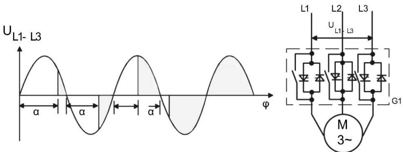
Figure 3-5 Phase angle control and schematic diagram of a two-phase controlled soft starter with integral bypass contacts
3.3.1 Method of operation of a two-phase controlled soft starter
A special method of operation is used for the SIRIUS 3RW30 and 3RW40 two-phase controlled soft starters based on SIEMENS' patented "polarity balancing" control principle.
Two-phase control
The SIRIUS 3RW30 and 3RW40 soft starters are two-phase controlled soft starters, in other words they are designed with two antiparallel thyristors in each of phases L1 and L3. Phase 2 is an uncontrolled phase, which is merely guided through the starter by a copper connection.
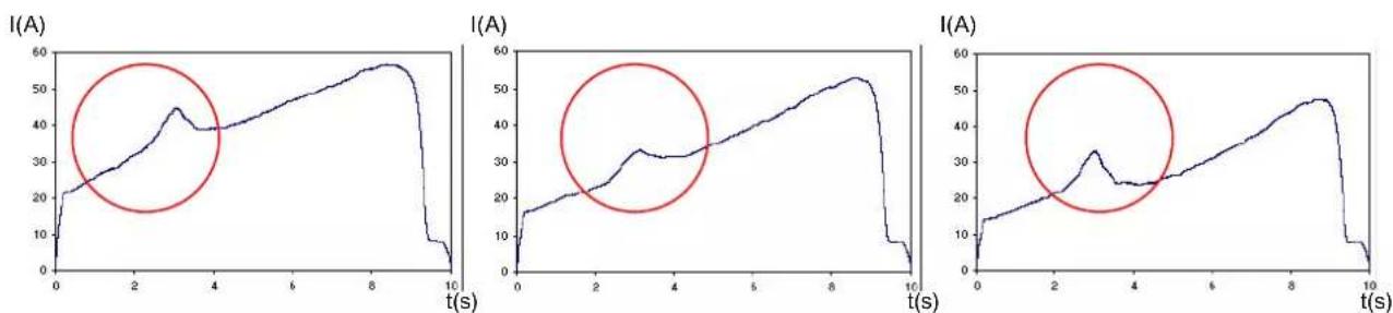
In a two-phase controlled soft starter, the current that results from the superimposition of the two controlled phases flows in the uncontrolled phase. The main advantages of two-phase control include the more compact size compared to a three-phase version and the lower hardware costs.
The occurrence of DC components, caused by the phase angle and the overlapping phase currents, is a negative physical effect of two-phase control during the startup process that can mean a louder noise is produced by the motor. The "polarity balancing" control principle was developed and patented by SIEMENS to prevent these DC components during starting.
line
| Time (s) | I(A) | | -------- | ---- | | 0 | 0 | | 1 | 20 | | 2 | 30 | | 3 | 45 | | 4 | 40 | | 5 | 45 | | 6 | 50 | | 7 | 55 | | 8 | 58 | | 9 | 55 | | 10 | 0 |Figure 3-6 Current characteristic and occurrence of DC components in the three phases without "polarity balancing"
Polarity balancing
"Polarity balancing" effectively eliminates these DC components during the ramp-up phase. It allows the motor to be started up with a constant speed, torque, and current rise.
The acoustic quality of the startup process comes very close to that of a three-phase controlled startup. This is made possible by the continuous dynamic alignment and balancing of current half-waves with different polarities during the motor startup.
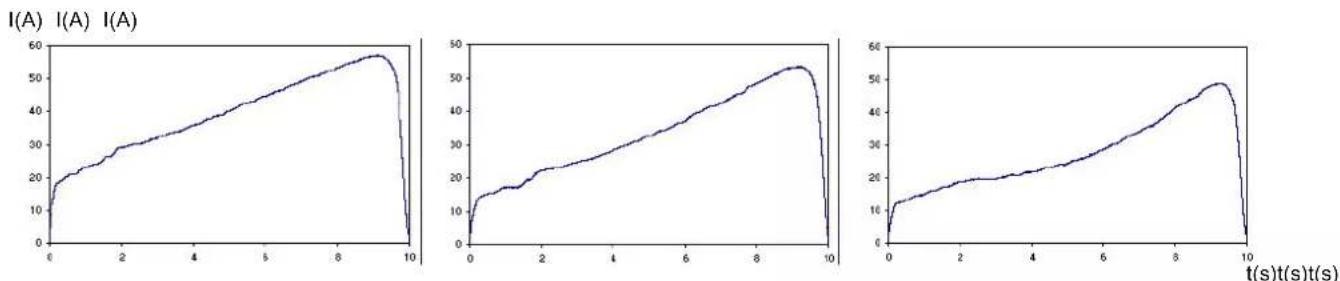
Figure 3-7 Current characteristic in the three phases without DC components thanks to "polarity balancing"
3.3.2 Starting current asymmetry
With two-phase control the starting current is asymmetrical for physical reasons, because the current in the uncontrolled phase is the sum of the currents in the two controlled phases.
This asymmetry can be as much as 30 to 40% during starting (ratio of minimum current to maximum current in all three phases).
Even though this cannot be influenced, it is not critical in most applications. It could cause an insufficiently rated fuse to trip in the uncontrolled phase, for instance. For recommended fuse ratings, refer to the tables in chapter Technical data [Page 121].
I(A) I(A) I(A)
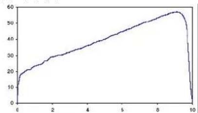
line
| x | y | |----|----| | 0 | 0 | | 1 | 20 | | 2 | 28 | | 3 | 34 | | 4 | 38 | | 5 | 44 | | 6 | 48 | | 7 | 52 | | 8 | 55 | | 9 | 58 | | 10 | 0 |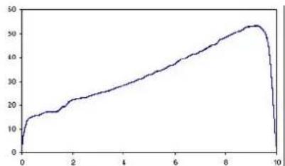
line
| x | y | |----|----| | 0 | 5 | | 1 | 15 | | 2 | 20 | | 3 | 25 | | 4 | 30 | | 5 | 35 | | 6 | 40 | | 7 | 45 | | 8 | 50 | | 9 | 55 | | 10 | 50 |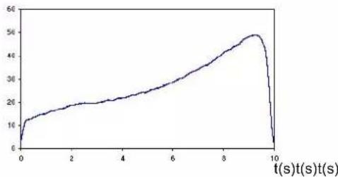
line
| t(s)t(s)t(s) | Value | | ------------ | ----- | | 0 | 10 | | 2 | 18 | | 4 | 22 | | 6 | 30 | | 8 | 40 | | 9 | 48 | | 10 | 0 |Figure 3-8 Starting current asymmetry
3.3 Functional principle of the SIRIUS 3RW30 and 3RW40 soft starters
Note
If wye-delta starters are exchanged for soft starters in an existing system, you should check the fuse ratings in the feeder in order to avoid false tripping. This is particularly important in connection with heavy-duty starting or if the fuse that is installed has already been operated close to the thermal tripping limit with the wye-delta assembly.
All elements of the main circuit (such as fuses, motor starter protectors, and switching devices) must be dimensioned for direct starting and according to the on-site short-circuit conditions, and ordered separately.
For recommended fuse and motor starter protector ratings for the feeder with soft starter, refer to chapter Technical data [Page 121].
3.3.3 Applications and use
Applications and selection criteria
The SIRIUS 3RW30 and 3RW40 soft starters represent a good alternative to direct or wye-delta starters.
The most important advantages are:
- Soft start
- Soft stop (3RW40 only)
- Uninterrupted switching without current peaks that place a heavy load on the system
- Simple installation and commissioning
- Compact, space-saving design
Applications
The typical applications include:
- Conveyor belts
- Roller conveyors
- Compressors
- F a n s
- P u m p s
- Hydraulic pumps
• Agitators
• Circular saws / band saws
Advantages
Conveyor belts and transport systems:
- Smooth starting
- Smooth stopping
Rotary pumps and piston pumps: - No pressure surges
- Increased service life of the pipe system
Agitators and mixers: - Reduced starting current
Fans:
• Protection for the gearbox and V belt
3.4 Comparison of device functions
3.4 Comparison of device functions
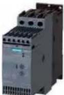 |  |  | 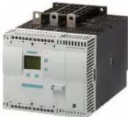 | ||
| SIRIUS 3RW30Standard applications | SIRIUS 3RW40Standard applications | SIRIUS 3RW44High Feature applications | |||
| Rated current at 40 °C / 50 °C | A | 3...106/3...98 | 12.5...432/11...385 | 29 ... 1214/26 ... 1076 | |
| Rated operational voltage | V | 200...480 | 200...600 | 200...690 | |
| Motor rating at 400 V / 460 V•Standard connection•Inside-delta circuit | kW/hp | 1.5...55/1.5...75 | 5.5...250/7.5...300 | 15...710/15...950 | |
| kW/hp | - | - | 22...1200/30...1700 | ||
| Ambient temperature | °C | -25...+60 | -25...+60 | 0...+60 | |
| Soft start/soft stop | √1) | √ | √ | ||
| Voltage ramp | √ | √ | √ | ||
| Starting/stopping voltage | % | 40...100 | 40...100 | 20...100 | |
| Ramp-up and ramp-down time | s | 0...20 | 0...20 | 1...360 | |
| Torque control | - | - | √ | ||
| Starting/stopping torque | % | - | - | 20...100 | |
| Torque limiting | % | - | - | 20...200 | |
| Ramp time | s | - | - | 1...360 | |
| Integrated jumper contact system | √ | √ | √ | ||
| Intrinsic device protection | - | √ | √ | ||
| Motor overload protection | - | √7) | √ | ||
| Thermistor motor protection | - | √2) | √ | ||
| Integrated remote RESET | - | √3) | √ | ||
| Settable current limiting | - | √ | √ | ||
| Inside-delta circuit | - | - | √ | ||
| Breakaway torque | - | - | √ | ||
| Creep speed in both directions of rotation | - | - | √ | ||
| Pump stop | - | - | 4) | ||
| DC braking | - | - | 4)5) | ||
| Combined braking | - | - | 4)5) | ||
| Motor heating | - | - | √ | ||
| Communication | - | - | With PROFIBUS DP (option) | ||
| External display and operator control module | - | - | (option) | ||
| Status measured value display | - | - | √ | ||
| Error log | - | - | √ | ||
| Events list | - | - | √ | ||
| Min/max pointer function | - | - | √ | ||
| Trace function | - | - | 6) | ||
| Programmable control inputs and outputs | - | - | √ | ||
| Number of parameter sets | 31 | 1 | |||
| Parameterizing software (SoftStarterES) | - | - | √ | ||
| Power semiconductors (thyristors) | 2 controlled phases | 2 controlled phases | 3 controlled phases | ||
| Screw terminals | √ | √ | √ | ||
| Spring-loaded terminals | √ | √ | √ | ||
| UL/CSA | √ | √ | √ | ||
| CE mark | √ | √ | √ | ||
| Soft starting under heavy-duty starting | - | - | 4) | ||
Support for configuration
√ Function available; – function not available.
1) For 3RW30 only soft start.
2) Optional up to size S3 (device variants).
Win-Soft Starter, electronic selection slider, Technical Assistance ++49 9118955900
3) For 3RW402. to 3RW404.; for
3RW405. and 3RW407. optional.
4) If necessary, overdimension soft starter and motor.
5) Not possible in inside-delta circuit.
6) Trace function with SoftStarterES software.
7) Acc. to ATEX
4.1 SIRIUS modular system
Switching, protecting, and starting motors
In order to simplify the assembly of load feeders, the SIRIUS modular system offers standard components that are optimally harmonized and are easy to combine. Just 7 sizes cover the entire performance range up to 250 kW / 300 hp. The individual switching devices can be assembled to form complete load feeders, either using link modules or by mounting directly.
For a selection of matching device combinations, e.g. soft starters and motor starter protectors, refer to chapter Technical data [Page 121].
For further information on individual products, refer to System manual (http://support.automation.siemens.com/WW/lisapi.dll?aktprim=0&lang=en&referer=%2fWW%2f&func=cslib.csinfo&siteid=csius&caller=view&extranet=standard&viewreg=WW&nodeid0=200259/9&objaction=csopen) "Innovations in the SIRIUS modular system", Order No. 3ZX1012-0RA01-1AB1.
4.1 SIRIUS modular system
SIRIUS motor starter protectors
3RV20 11 (S00)
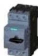
3RV20 21 (S0)
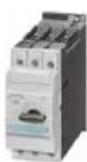
3RV10 31 (S2)
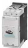
3RV10 41 (S3)
SENTRON circuit breakers
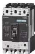
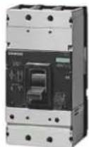
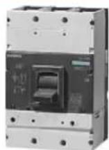
VL250/3VL3
VL400/3VL4
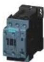
SIRIUS contactors

3RT20 1 (S00)
3RT20 2 (S0)
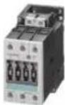
3RT10 3 (S2)
3RT1.4(S3)
3RT1.5(S6)
3RT1.6 (S10)
natural_image
Exterior view of a black industrial electrical contactor with mounting holes (no visible text or symbols)3RT1.7 (S12)
SIRIUS overload relays

3RB30 16 (S00)

3RB30 26 ( S0)

3RB20 36 (S2)
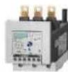
3RB20 46 (S3)
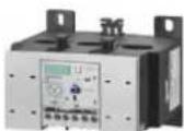
3RB20 56 (S6)
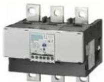
3RB20 66 (S10/S12)
SIRIUS soft starters
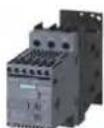
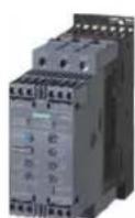
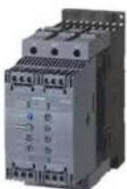
3RW30 1 (S00) 3RW40 2 (S0) 3RW40 3 (S2) 3RW40 4 (S3)
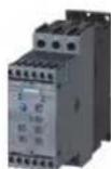
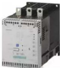
Figure 4-1 SIRIUS modular system
natural_image
Industrial control unit with multiple ports and indicator lights (no visible text or symbols)3RW40 5 (S6) 3RW40 7 (S10/S12)
natural_image
Exterior view of a white industrial electrical contactor device (no visible text or symbols)Functions
5.1 Start modes
You can choose between different startup functions reflecting the wide range of applications and functionality of the SIRIUS 3RW30 and 3RW40 soft starters. The motor start can be optimally adapted to each particular application.
5.1.1 Voltage ramp
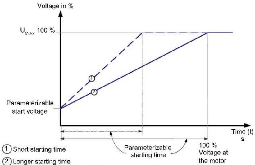
The SIRIUS 3RW30 and 3RW40 soft starters achieve soft starting by means of a voltage ramp. The motor terminal voltage is increased from a parameterizable starting voltage up to the mains voltage within a definable ramp-up time.
Starting voltage
The starting voltage determines the starting torque of the motor. A lower starting voltage results in a lower starting torque and a lower starting current. The starting voltage selected must be sufficiently high to ensure that motor starts up smoothly as soon as the start command is received by the soft starter.
Ramp time
The length of the set ramp time determines the time taken to increase the motor voltage from the parameterized starting voltage to the mains voltage. This influences the motor's acceleration torque, which drives the load during the ramp-up process. A longer ramp time results in a lower acceleration torque as the motor is started up. The startup is slower and smoother as a result. The ramp time should be long enough for the motor to reach its nominal speed. If the time selected is too short, in other words if the ramp time ends before the motor has started up successfully, a very high starting current that can even equal the direct starting current at the same speed occurs at this instant.
The SIRIUS 3RW40 soft starter limits the current to the value set with the current limiting potentiometer (refer to chapter Current limiting and ramp-up detection (3RW40 only) [Page 29]). As soon as the current limiting value is also reached, the voltage ramp or the ramp time is interrupted and the motor is started with the current limiting value until it has started up successfully. In this case, the motor ramp-up time may be longer than the maximum parameterizable 20 seconds ramp time (for further information about the maximum ramp-up times and switching frequencies, refer to chapter 3RW40 2. to 7. power electronics [Page 148] ff).
The SIRIUS 3RW40 soft starter has intrinsic device protection, current limiting, and ramp-up detection functions. These functions do not form part of the SIRIUS 3RW30 soft starter.
5.1 Start modes
CAUTION
Risk of property damage
When using the 3RW30: Make sure the selected ramp time is longer than the actual motor ramp-up time. If not, the SIRIUS 3RW30 may be damaged because the internal bypass contacts close when the set ramp time elapses. If the motor has not finished starting up, an AC3 current that could damage the bypass contact system will flow.
When using the 3RW40: The 3RW40 has an integrated ramp-up detection function that prevents this operating state from occurring.
The maximum ramp time for the SIRIUS 3RW30 soft starter is 20 seconds An appropriately dimensioned SIRIUS 3RW40 or 3RW44 soft starter should be chosen for startup processes with a motor ramp-up time > 20 seconds.
line
| Parameterizable starting voltage | Voltage at the motor | | -------------------------------- | -------------------- | | 0 | 0 | | 1 | 100 | | 2 | 100 |Figure 5-1 Principle of the voltage ramp
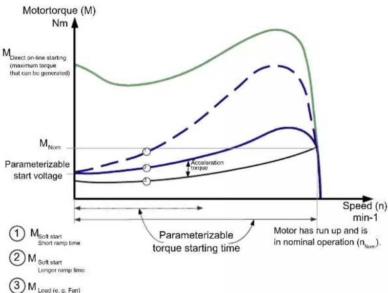
Figure 5-2 Principle of the voltage ramp for the torque characteristic
line
| Motor speed n | I_Direct on-line starting | I_Soft starter | | ------------- | ------------------------- | -------------- | | n | High | Low | | n_Nom | Low | High |Figure 5-3 Principle of the voltage ramp for the starting current characteristic
Typical applications of the voltage ramp
The voltage ramp principle is valid for all applications, e.g. pumps, compressors, conveyor belts.
5.1.2 Current limiting and ramp-up detection (3RW40 only)
The SIRIUS 3RW40 soft starter measures the phase current (motor current) continuously with the help of integrated current transformers.
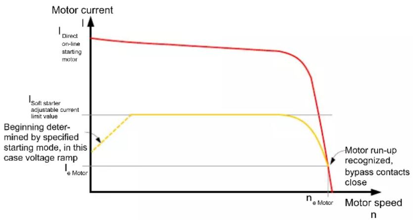
The motor current that flows during the startup process can be actively limited by means of the soft starter. The current limiting function takes priority over the voltage ramp function. As soon as a parameterizable current limit is reached, in other words, the voltage ramp is interrupted and the motor is started with the current limiting value until it has started up successfully. The current limiting function is always active with SIRIUS 3RW40 soft starters. If the current limiting potentiometer is set to the clockwise stop (maximum), the starting current is limited to five times the set rated motor current.
Current limiting value
The current limiting value is set to the current required during starting as a factor of the rated motor current. Since the starting current is asymmetrical, the set current corresponds to the arithmetic mean value for the three phases.
Example
If the current limiting value is set to 100 A, the currents might be approx. 80 A in L1, 120 A in L2, and 100 A in L3 (refer to chapter Starting current asymmetry [Page 21]).
5.2 Stop modes
As soon as the selected current limiting value is reached, the motor voltage is reduced or controlled by the soft starter to prevent the current from exceeding the limit. The set current limiting value must be high enough to ensure that the torque generated in the motor is sufficient to accelerate the motor to nominal speed. Three to four times the value of the motor's rated operational current (le) can be assumed as typical here.
The current limiting function is always active because it is required by the intrinsic device protection. If the current limiting potentiometer is set to the clockwise stop (maximum), the starting current is limited to five times the set rated motor current.
Ramp-up detection (3RW40 only)
The SIRIUS 3RW40 soft starter is equipped with an integrated ramp-up detection function. If it detects a motor startup, the motor voltage is immediately increased to 100 % of the mains voltage. The internal bypass contacts close and the thyristors are bridged.
line
| Motor speed n | Current (I) | | ------------- | ----------- | | 0 | Direct on-line starting motor | | e Motor | Soft starter adjustable current limit value | | n_e Motor | Motor run-up recognized, bypass contacts close |Figure 5-4 Current limiting with soft starter
Typical applications for current limiting
Current limiting is used for applications with large centrifugal masses (mass inertias) and therefore longer ramp-up times, e.g. fans, circular saws etc.
5.2 Stop modes
You can choose between different stop modes reflecting the wide range of applications for SIRIUS soft starters. The motor stop can be optimally adapted to each particular application.
If a start command is issued during the stop process, the process is interrupted and the motor is started again with the set start mode.
Note
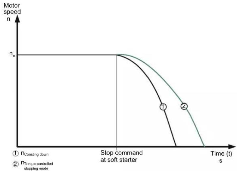
If you select "soft stop" (3RW40 only) as the stop mode, the feeder (soft starter, cables, feeder protective devices, and motor) may need to be dimensioned for higher values because the current exceeds the rated motor current during the stop process.
line
| Time (s) | n_Torque-controlled stopping mode | n_Torque-controlled stopping mode | | -------- | ----------------------------------- | ----------------------------------- | | 0 | n_e | n_e | | ~1.5 | n_e | n_e | | >1.5 | 0 | 0 |5.2.1 Stop without load (3RW30 and 3RW40)
"Stop without load" means the power supplied to the motor via the soft starter is interrupted when the ON command is removed from the starter. The motor coasts to a standstill, driven only by the mass inertia (centrifugal mass) of the rotor and load. This is also referred to as a natural stop. A large centrifugal mass means a longer stop time without load.
Typical applications for stop without load
Stop without load is used for loads that place no special demands on the startup characteristic, e.g. fans.
5.2.2 Soft stop (3RW40 only)
In "soft stop" mode, the natural stop process of the load is decelerated. The function is used when the load must be prevented from stopping abruptly. This is typically the case in applications with a low mass inertia or a high counter-torque.
Ramp-down time
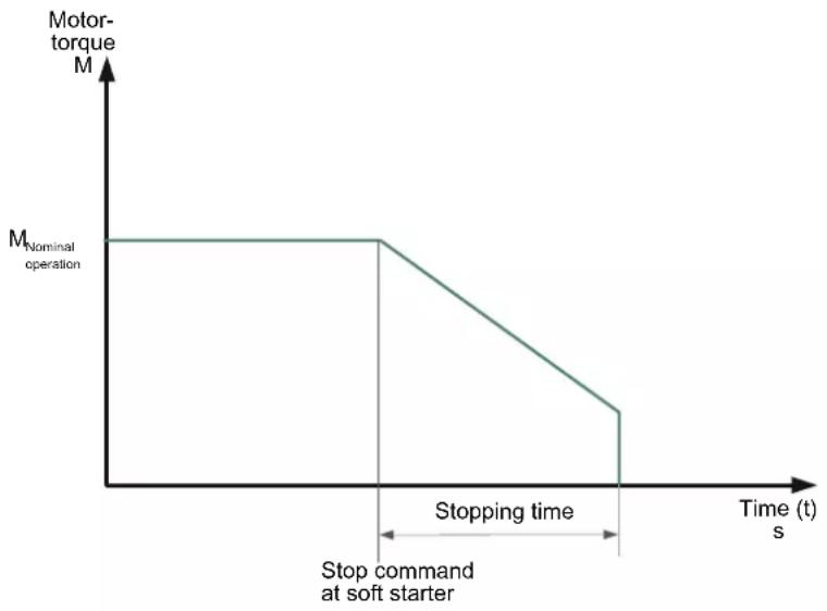
The "Ramp-down time" potentiometer on the soft starter allows you to specify how long power should still be supplied to the motor after the ON command is removed. The torque generated in the motor is reduced by means of a voltage ramp function within this ramp-down time and the application stops smoothly.
If the motor is stopped abruptly in pump applications, as is normal with wye-delta or direct starting, for instance, water hammer can occur. Water hammer is caused by the sudden flow separation, leading to pressure fluctuations on the pump. It has the effect of producing noise and mechanical impacts on the pipelines as well as on any flaps and valves installed there.
5.3 Motor protection / intrinsic device protection (3RW40 only)
Water hammer can be reduced compared to direct or wye-delta starting by using the SIRIUS 3RW40 soft starter. An optimum pump stop is achieved using a SIRIUS 3RW44 soft starter with an integrated pump stop function (refer to chapter Comparison of device functions [Page 24]).
line
| Time (s) | Motor-torque M | | -------- | -------------- | | 0 | M_Nominal operation | | 1 | M_Nominal operation | | 2 | M | | 3 | 0 | | 4 | 0 | | 5 | 0 |Typical applications for soft stop
Use soft stop for
• Pumps to reduce water hammer.
- Conveyor belts to prevent the conveyed product from tilting.
5.3 Motor protection / intrinsic device protection (3RW40 only)
NOTICE
If the soft starter is disconnected because the motor overload protection or the intrinsic device protection trips, you must wait a defined cooling time (recovery time) prior to acknowledging the fault or starting the motor again. (Motor overload tripping time: 60 seconds, temperature sensor: after cooling, intrinsic device protection tripping time: >30 seconds)
5.3.1 Motor protection function
The motor overload protection function is implemented on the basis of the winding temperature. This indicates whether the motor is overloaded or functioning in the normal operating range.
The winding temperature can either be calculated with the help of the integrated, electronic motor overload function or measured with a connected motor thermistor.
The two types of protection must be combined to achieve full motor protection. This combination is recommended to protect the motor optimally.
Note
Thermistor motor protection evaluation
The thermistor motor protection evaluation function is optionally available for the SIRIUS 3RW40 2 to 3RW40 4 soft starters in the 24 V AC/DC control voltage version.
Motor overload protection
The current flow during motor operation is measured by measuring the current with transformers integrated in the soft starter. The temperature rise in the winding is calculated based on the rated operational current set for the motor.
A trip is generated by the soft starter when the characteristic is reached, depending on the trip class (CLASS setting).
ATEX
"Increased safety" type of protection EEx e acc. to ATEX Directive 94/9/EC
The SIRIUS 3RW40 soft starter sizes S0 to S12 are suitable for starting explosion-proof motors with the "increased safety" type of protection EEx e (type of protection / marking: Ex II (2) GD).
Wire the fault output (95 96) to an upstream switching device in such a way that if a fault occurs, this device disconnects the feeder (refer to Fig. "3RW40 wiring fault with 3RV").
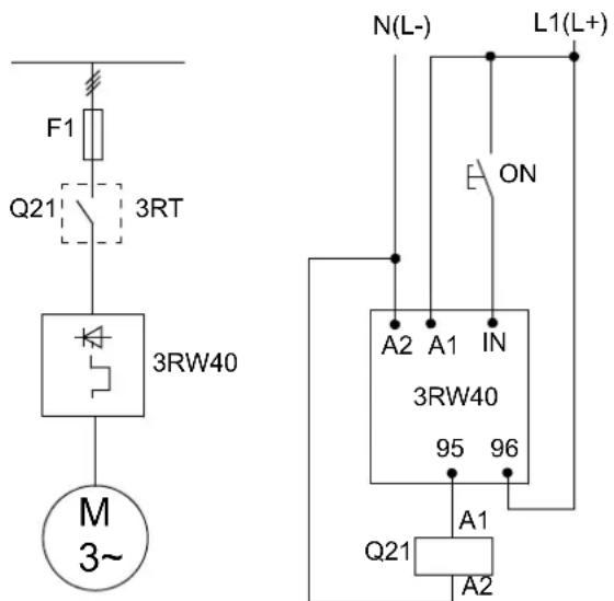
Figure 5-5 3RW40 wiring fault
5.3 Motor protection / intrinsic device protection (3RW40 only)
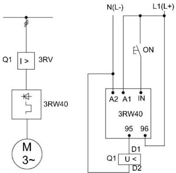
Figure 5-6 3RW40 wiring fault with 3RV
For further information, refer to the operating instructions, Order No. 3ZX1012-0RW40-1CA1 (http://support.automation.siemens.com/WW/view/de/22809303).

WARNING
Danger of death or serious injury.
The 3RW40 is not suitable for installation in hazardous areas. The device is only allowed to be installed in a control cabinet with the IP4x degree of protection. Appropriate measures (e.g. encapsulation) must be taken if it is to be installed in a hazardous area.
Trip class (electronic overload protection)
The trip class (CLASS) specifies the maximum time within which a protective device must trip from a cold state at 7.2 × the rated operational current (motor protection to IEC 60947). The tripping characteristics represent this time as a function of the tripping current (refer to chapter Motor protection tripping characteristics for 3RW40 (with symmetry) [Page 161]). You can set different CLASS characteristics according to the startup class.
Note
The rated data of the soft starters refers to normal starting (CLASS 10). The starters may need to be calculated with a size allowance for heavy-duty starting (>CLASS 10). You can only set a rated motor current that is lower than the soft starter rated current (for the permissible settings, refer to chapter [Technical data [Page 121]).
Recovery time (motor overload protection)
A recovery time of 60 seconds, during which the motor cools down and cannot be restarted, starts if the thermal motor model is tripped.
Protection against voltage failure in the event of a fault
If the control supply voltage fails during a trip, the current tripping state of the thermal motor model and the current recovery time are stored in the soft starter. When the control supply voltage is restored, the current tripping state of the thermal motor model and the intrinsic device protection prior to the power failure are likewise automatically restored. If the control voltage is disconnected during operation (without a preceding fault trip), the starter is not protected against voltage failure.
Temperature sensor
Note
Temperature sensor
The temperature sensor evaluation function is optionally available for the SIRIUS 3RW40 24 to 3RW40 47 soft starters in the 24 V AC/DC control voltage version.
This motor protection function measures the motor's stator winding temperature directly with the help of a sensor installed in the motor, in other words the motor must have a sensor wound into the stator winding.
You can choose between two different sensor types for the evaluation.
-
Type A PTC thermistors ("type A sensors") for connection to terminals T11/21 and T12
-
Thermoclick sensors for connection to terminals T11/21 and T22
The wiring and sensors are monitored for wire breakage and short-circuits.
Recovery time (thermistor motor protection)
If the thermistor motor protection is tripped, the soft starter cannot be restarted until the sensor installed in the motor has cooled down. The recovery time varies according to the temperature state of the sensor.
5.3.2 Intrinsic device protection (3RW40 only)
Thyristor protection (thermal)
SIRIUS 3RW40 soft starters are equipped with integrated intrinsic device protection to prevent thermal overloading of the thyristors.
This is achieved on the one hand by means of current measuring transformers in the three phases and on the other, by measuring the temperature with temperature sensors on the thyristor's heat sink.
If the fixed, internally set trip value is exceeded, the soft starter is automatically disconnected.
Recovery time (intrinsic device protection)
If the intrinsic device protection is tripped, the soft starter cannot be restarted until a recovery time of at least 30 seconds has elapsed.
5.4 Functions of the RESET buttons
Thyristor protection (short-circuit)
SITOR semiconductor fuses must be connected upstream to protect the thyristors against short-circuits (e.g. in case of cable damage or an interturn fault in the motor; refer to chapter Soft starter assembly with type of coordination 2 [Page 61]). For the fuse selection tables, refer to chapter Technical data [Page 121].
Protection against voltage failure (in the event of a fault)
If the control supply voltage fails during a trip, the current tripping state of the thermal intrinsic device protection model and the current recovery time are stored in the soft starter. When the control supply voltage is restored, the current tripping state of the thermal intrinsic device protection prior to the power failure are likewise automatically restored.
NOTICE
If the control voltage is disconnected during operation (e.g. in "automatic mode"), the starter is not protected against voltage failure. You must wait five minutes between two starts to ensure that the motor protection and the intrinsic device protection are working correctly.
5.4 Functions of the RESET buttons
5.4.1 SIRIUS 3RW40 2, 3RW40 3, and 3RW40 4 soft starters
5.4.1.1 RESET MODE button and LED
By pressing the RESET MODE button, you define the reset procedure in case of a fault. This is indicated by the RESET MODE LED.
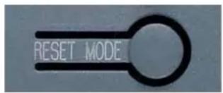
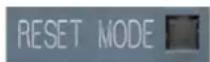
Yellow = AUTO
Off = MANUAL
Green = REMOTE
Note
On the SIRIUS 3RW40 2. soft starter, the RESET MODE button is located underneath the label (refer to chapter Operator controls, displays, and connections on the 3RW40 [Page 70])
5.4.1.2 Manual RESET
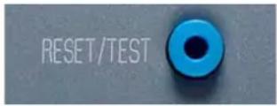
Manual RESET with the RESET / TEST button (RESET MODE LED = off)
You can reset a fault by pressing the RESET / TEST button.
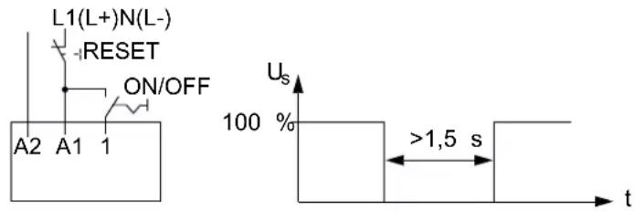
5.4.1.3 Remote RESET
Remote RESET (RESET MODE LED = green)
You can reset a fault signal by disconnecting the control supply voltage for >1.5 s.
5.4.1.4 AUTO RESET
AUTO RESET (RESET MODE LED = yellow)
If you set the RESET mode to AUTO, a fault is automatically reset as follows:
- If the motor overload protection function trips: after 60 s
- If the intrinsic device protection function trips: after 30 s
- If the thermistor evaluation function trips: after the temperature sensor in the motor has cooled down

WARNING
Automatic restart
Danger of death, serious injury, or property damage.
The automatic RESET mode (AUTO RESET) must not be used in applications where there is a risk of serious injury to persons or substantial damage to property if the motor starts up again unexpectedly. The start command (e.g. issued by a contact or the PLC) must be reset prior to issuing a RESET command because the motor attempts to restart again automatically following this RESET command if a start command is still present. This particularly applies if the motor protection has tripped. For safety reasons, you are advised to integrate the group fault output (terminals 95 and 96) in the controller.
5.4.1.5 Acknowledging faults
For information about whether or not faults can be acknowledged as well as the corresponding LED and output contact states, refer to chapter Diagnostics and fault signals [Page 44].
5.4 Functions of the RESET buttons
5.4.2 SIRIUS 3RW40 5 and 3RW40 7 soft starters
5.4.2.1 RESET MODE button and AUTO LED
By pressing the RESET MODE button, you define the reset procedure in case of a fault. This is indicated by the AUTO LED.
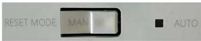
Yellow = AUTO
Off = MANUAL (REMOTE)
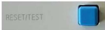
5.4.2.2 Manual RESET
Manual RESET with the RESET / TEST button (AUTO LED = off)
You can reset a fault by pressing the RESET / TEST button.
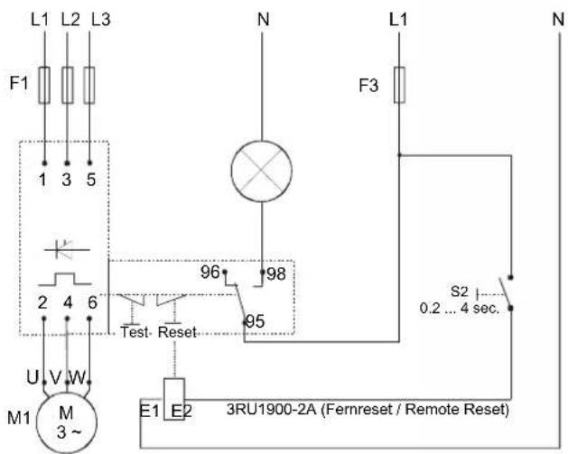
5.4.2.3 Remote RESET
Remote RESET (AUTO LED = green)
You can initiate a remote RESET by controlling the optional module for RESET (3RU1900-2A).
5.4.2.4 AUTO RESET
AUTO RESET (AUTO LED = yellow)
If you set the RESET mode to AUTO, a fault is automatically reset as follows:
- If the motor overload protection function trips: after 60 s
- If the intrinsic device protection function trips: after 30 s

WARNING
Automatic restart
Can result in death, serious injury, or property damage.
The automatic RESET mode (AUTO RESET) must not be used in applications where there is a risk of serious injury to persons or substantial damage to property if the motor starts up again unexpectedly. The start command (e.g. issued by a contact or the PLC) must be reset prior to issuing a RESET command because the motor attempts to restart again automatically following this RESET command if a start command is still present. This particularly applies if the motor protection has tripped. For safety reasons, you are advised to integrate the group fault output (terminals 95 and 96) in the controller.
5.4.2.5 Acknowledging faults
For information about whether or not faults can be acknowledged as well as the corresponding LED and output contact states, refer to chapter Diagnostics and fault signals [Page 44].
5.4.3 Other functions of the RESET button
5.4.3.1 Motor protection trip test
You initiate a motor overload trip by pressing the RESET / TEST button for longer than five seconds. The SIRIUS 3RW40 soft starter is tripped by the fault signal at the OVERLOAD LED, the FAILURE / OVERLOAD contact 95-98 closes, and the motor that is connected and running is switched off.
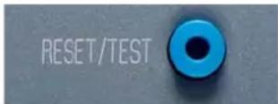
RESET / TEST button on the 3RW40 2, 3RW40 3, and 3RW40 4
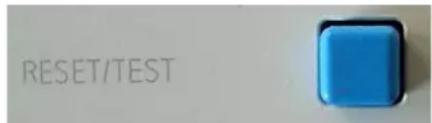
RESET / TEST button on the 3RW40 5 and 3RW40 7
5.4.3.2 Reparameterizing the ON / RUN output contact
For information about reparameterizing the output with the RESET / TEST button, refer to chapter Parameterizing the 3RW40 outputs [Page 110].
5.5 Functions of the inputs
5.5 Functions of the inputs
5.5.1 Start input (terminal 1) on 3RW30 and 3RW40 2 to 3RW40 4
Rated control voltage is present at terminal A1 / A2: The startup process of the soft starter begins when a signal is present at terminal 1 (IN). The starter operates until the signal is removed again.
If a ramp-down time is parameterized (3RW40 only), a soft stop starts as soon as the signal is removed.
The potential of the signal at terminal 1 must correspond to the potential of the rated control voltage at terminal A1 / A2.
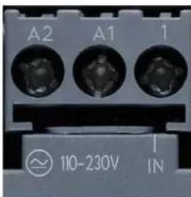
For recommended circuits, e.g. control by means of pushbuttons, contactor contacts, or a PLC, refer to chapter Typical circuit diagrams [Page 167].
5.5.2 Start input (terminal 3) on 3RW40 5 and 3RW40 7
Rated control voltage is present at terminal A1 / A2: The startup process of the soft starter begins when a signal is present at terminal 3 (IN). The starter operates until the signal is removed again. If a ramp-down time is parameterized, a soft stop starts as soon as the signal is removed.
The 24 V DC control voltage supplied by the soft starter must be taken from terminal 1 (+) as voltage for the signal at terminal 3.
If you select direct control by a PLC, the "M" of the PLC's reference potential must be connected to terminal 2 (-).
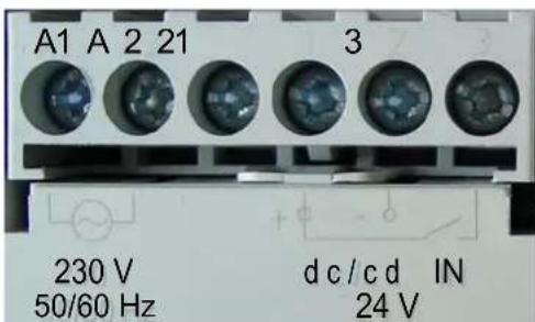
For recommended circuits, e.g. control by means of pushbuttons, contactor contacts, or a PLC, refer to chapter Typical circuit diagrams [Page 167].
5.5.3 Thermistor input / connection on 3RW40 2 to 3RW40 4
24 V AC/DC rated control voltage
After removing the copper jumper between T11/21 and T22, you can connect and evaluate either a Klixon thermistor integrated in the motor winding (at terminal T11/T21-T22) or a type A PTC (at terminal T11/T21-T12).
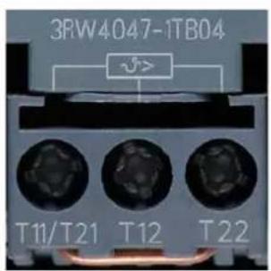
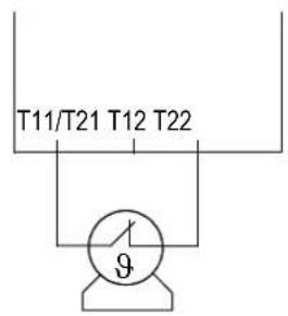
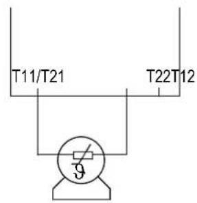
Klixon Type A PTC
5.6 Functions of the outputs
5.6.1 3RW30: Output terminal 13 / 14 ON
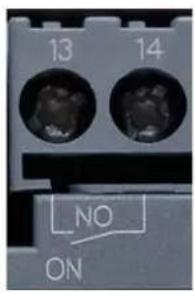
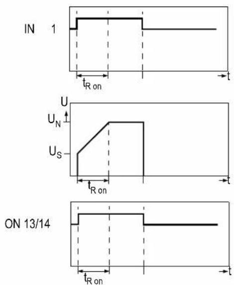
The potential-free output contact at terminal 13/14 (ON) closes if a signal is present at terminal 1 (IN); it remains closed until the start command is removed.
The output can be used, for instance, to control a line contactor connected upstream or to implement latching if you selected pushbutton control. For recommended circuits, refer to chapter Typical circuit diagrams [Page 167].
line
| Time | U (V) | Us (V) | |------|-------|--------| | t_R on | U | U_S | | t | U | U_N | | t_R on | U | U_S | | t | U | U_N | | t | U | U_S | | t_R on | U | U_N | | t | U | U_S | | t | U | U_N | | t | U | U_S | | t | U | U_N | | t | U | U_S | | t | U | U_N | | t | U | U_S | | t | U | U_N | | t | U | U_S | | t | U | U_N | | t = ON 13/14 | U | U_S | | t = ON 13/14 | U | U_N | | t = ON 13/14 | U | U_S | | t = ON 13/14 | U | U_N | | t = ON 13/14 | U | U_S | | t = ON 13/14 | U | U_N | | t = ON 13/14 | U | T_R on | | t = ON 13/14 | U | T_R on | | t = ON 13/14 | U | T_R on | | t = ON 13/14 | U | T_R on | | t = ON 13/14 | U | T_R on | | t = ON 13/14 | U | T_R on | | t - ON 13/14 | U | U_S | | t - ON 13/14 | U | U_N | | t - ON 13/14 | U | U_S | | t - ON 13/14 | U | U_N | | t - ON 13/14 | U | U_S | | t - ON 13/14 | U | U_N | | t - ON 13/14 | U | T_R on | | t - ON 13/14 | U | T_R on | | t - ON 13/14 | U | T_R on | | t - ON 13/14 | U | T_R on | | t - ON 13/14 | U | T_R on | | t - ON 13/14 | U | T_R on | | t = ON 13/14 | U | U_S | | t = ON 13/14 | U | U_N | | t = ON 13/14 | U | U_S | | t = ON 13/14 | U | U_N | | t = ON 13/14 | U | U_S | | t - ON 13/14 | U | U_S | | t - ON 13/14 | U | U_N | | t - ON 13/14 | U | U_S | | t - ON 13/14 | U | U_N | | t - ON 13/14 | U | U_S | | t - ON 13/14 | U | U_S | | t - ON 13/14 | U | U_N | | t - ON 13/14 | U | U_S | | t - ON 13/14 | U | U_N | | t - ON 13/14 | U | U_S | | t - ON 13/14 | T_R on | T_R on | | t - ON 13/14 | T_R on | T_R on | | t - ON 13/14 | T_R on | T_R on | | t - ON 13/14 | T_R on | T_R on | | t - ON 13/14 | T_R on | T_R on | | t - ON 13/14 | T_R on | T_R at End: ~0.5s, then ~0.5s, then ~0.5s, then ~0.5s, then ~0.5s, then ~0.5s, then ~0.5s, then ~0.5s, then ~0.5s, then ~0.5s, then ~0.5s, then ~0.5s, then ~0.5s, then ~0.5s, then ~0.5s, then ~T_R on: ~0.5s, then ~0.5s, then ~0.5s, then ~0.5s, then ~0.5s, then ~0.5s, then ~0.5s, then ~0.5s, then ~0.5s, then ~0.5s, then ~0.5s, then ~T_R on: ~0.5s, then ~0.5s, then ~0.8s, then ~0.8s, then ~0.8s, then ~0.8s, then ~0.8s, then ~0.8s, then ~0.8s, then ~0.8s, then ~0.8s, then ~0.8s, then ~0.8s, then ~0.8s, then ~0.8s, then ~0.8s, then ~T_R on: ~0.5s, then ~0.5s, then ~0.8s, then ~0.8s, then ~0.8s, then ~0.8s, then ~0.8s, then ~0.8s, then ~0.8s, then ~0.8s, then ~0.8s, then ~0.8s, then ~T_R on: ~0.5s, then ~0.5s, then ~0.8s, then >0.5s, then >0.8s, then >0.8s, then >0.8s, then >0.8s, then >0.8s, then >0.8s, then >0.8s, then >0.8s, then >0.8s, then >0.8s, then >T_R on: >0.5s, then >0.5s, then >0.8s, then >0.8s, then >0.8s, then >0.8s, then >0.8s, then >0.8s, then >0.8s, then >0.8s, then >T_R on: >0.5s, then >0.5s, then >0.8s, then >0.8s, then >0.8s, then5.6 Functions of the outputs
For a state diagram of the contact in the various operating states, refer to chapter Diagnostics and fault signals [Page 44].
5.6.2 3RW40: Output terminals 13 / 14 ON / RUN and 23 / 24 BYPASSED
ON
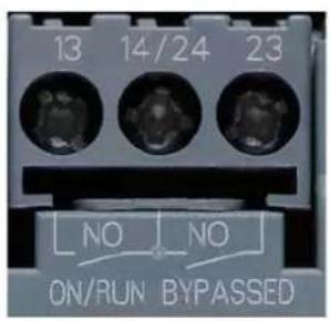
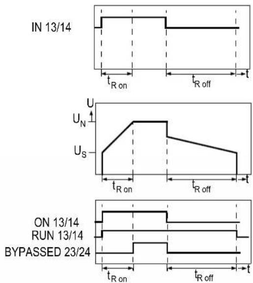
The potential-free output contact at terminal 13/14 (ON) closes if a signal is present at terminal 1 (IN); it remains closed until the start command is removed (factory default). The ON function can be used, for instance, as a latching contact if you selected pushbutton control.
Reparameterizing from ON to RUN
You can reparameterize the function of the ON output on the 3RW40 to RUN by simultaneously pressing the RESET TEST and RESET MODE buttons (refer to chapter Commissioning the 3RW40 [Page 98]).
RUN
The RUN output remains closed as long as the motor is controlled by the soft starter, in other words during the startup phase, in bypass mode, and during the soft stop (if set). This output function can be used, for instance, if a line contactor connected upstream must be controlled by the soft starter, especially if the soft stop function is set.
BYPASSED
The BYPASSED function can be used, for instance, to indicate that the motor has started up successfully.
The BYPASSED output at terminal 23 / 24 closes as soon as the SIRIUS 3RW40 soft starter detects that the motor has started up (refer to chapter Ramp-up detection [Page 104]).
The integral bypass contacts simultaneously close and the thyristors are bridged. The integral bypass contacts and output 23 / 24 open again as soon as the start input IN is removed.
other
| Time | IN 13/14 (t_R on) | IN 13/14 (t_R off) | U_N (t_R on) | U_N (t_R off) | U_S (t_R on) | U_S (t_R off) | |------|-------------------|--------------------|--------------|---------------|--------------|---------------| | Start | High | High | Low | Low | Low | Low | | Mid | Medium | Medium | High | High | Medium | High | | End | Low | Low | Low | Low | Low | Low |For a state diagram of the contacts and the LEDs in the various operating and fault states, refer to chapter Diagnostics and fault signals [Page 44].
For recommended circuits, refer to chapter typical circuit diagrams [Page 167].
5.6.3 3RW40: Group fault output at terminal 95 / 96 / 98 OVERLOAD / FAILURE
If there is no rated control voltage or if a failure occurs, the potential-free FAILURE / OVERLOAD output is switched.
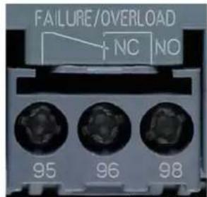
For recommended circuits, refer to chapter Typical circuit diagrams [Page 167].
For a state diagram of the contacts in the various fault and operating states, refer to chapter Diagnostics and fault signals [Page 44].
5.7 Diagnostics and fault signals
5.7 Diagnostics and fault signals
5.7.1 3RW30: LEDs and troubleshooting
| LEDs on 3RW30 | Auxiliary contact | |||
| Soft starter | ||||
| 3RW30 | DEVICE(rd/gn/ylw) | STATE/BYPASSED/FAILURE(gn/rd) | 13 14/(ON) | |
| U_S=0 | ||||
| Operating state | IN | |||
| Off | 0 | |||
| Start | 1 | |||
| Bypassed | 1 | |||
| Fault | ||||
| Impermissible electronics supply voltage1) | ||||
| Bypass overload2) | ||||
| -Missing load voltage1)-Phase failure, missing load1) | ||||
| Device fault3) | ||||
| LEDs | |||||
| = | = | ylwrd gn | |||
| Off= | ON | Flashing | Green= | Red=Yellow | = |
1) The fault is automatically reset by an outgoing event. An automatic restart is initiated and the 3RW restarted if a start command is present at the input.
| WARNING |
| Automatic restartDanger of death, serious injury, or property damage.If you do not want the motor to start automatically, you must integrate suitable additional components, e.g. phase failure or load monitoring devices, into the control and main circuits. |
2) The fault can be acknowledged by removing the start command at the start input.
3) Switch off the control voltage, then switch it on again. If the fault is still present, contact your SIEMENS partner or Technical Assistance.
For notes on troubleshooting, refer to the table below.
| Fault Cause Remedy | ||
| Impermissible electronics supply voltage | The control supply voltage does not correspond to the soft starter's rated voltage. | Check the control supply voltage; an incorrect control supply voltage could be caused by a power failure or a voltage dip. |
| Bypass overload A current > 3.5 x I | _e of the soft starter occurs for > 60 ms in bypass mode (e.g. because the motor is blocked). | Check the motor and load, and check the soft starter's dimensions. |
| Missing load voltage, phase failure / missing load | Cause 1: Phase L1 / L2 / L3 is missing or fails / collapses when the motor is operating.Tripped as a result of a dip in the permissible rated operational voltage > 15 % for > 100 ms during the startup process or > 200 ms in bypass mode. | Connect L1 / L2 / L3 or correct the voltage dip. |
| Cause 2: The motor that is connected is too small and the fault occurs as soon as it is switched to bypass mode. | If less than 10 % of the soft starter's rated current is flowing, the motor cannot be operated with soft starter. Use another soft starter. | |
| Cause 3: Motor phase T1 / T2 / T3 is not connected. | Connect the motor properly (e.g. jumpers in the motor terminal box, repair switch closed etc.) | |
| Device fault Soft starter defective. | Contact your SIEMENS partner or | Technical Assistance. |
5.7 Diagnostics and fault signals
5.7.2 3RW40: LEDs and troubleshooting
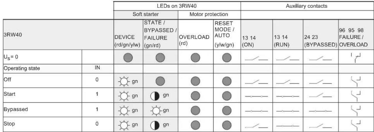 |
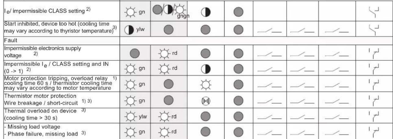 |
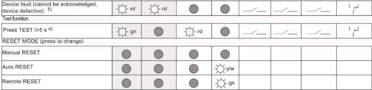 |
 |

WARNING
Automatic restart
Can result in death, serious injury, or property damage.
The automatic RESET mode (AUTO RESET) must not be used in applications where there is a risk of serious injury to persons or substantial damage to property if the motor starts up again unexpectedly. The start command (e.g. issued by a contact or the PLC) must be reset prior to issuing a RESET command because the motor attempts to restart again automatically following this RESET command if a start command is still present. This particularly applies if the motor protection has tripped. For safety reasons, you are advised to integrate the group fault output on the 3RW40 (terminals 95 and 96), or the signaling contact of the motor or miniature circuit breaker on all devices, in the controller.
Notes on troubleshooting
| Warning Cause Remedy | ||
| Impermissible I_e CLASS setting(control voltage present, no start command) | The rated operational current I_e set for the motor (control voltage present, no start command) exceeds the associated, maximum permissible setting current referred to the selected CLASS setting (chapterMotor current settings [Page 107]). | Check the rated operational current set for the motor, select a lower CLASS setting, or calculate the soft starter with a size allowance.As long as the 3RW40 is not controlled IN (0->1), this is only a status signal. However, it becomes a fault signal if the start command is applied. |
| Start inhibited, device too hot The acknowledgment and the motor start are inhibited for a defined time by the inherent device protection following an overload trip, to allow the 3RW40 to cool down.Possible causesToo many starts,Motor ramp-up time too long,Ambient temperature in switching device's environment too high,Minimum installation clearances not complied with. | The device cannot be started until the temperature of the thyristor or the heat sink has cooled down enough to guarantee sufficient reserve for a successful startup. The time until restarting is allowed can vary but is a minimum of 30 s.Rectify the causes and possibly retrofit the optional fan (3RW40 2. to 3RW40 4.). | |
5.7 Diagnostics and fault signals
| Fault Cause Remedy | ||
| Impermissible electronics supply voltage: | The control supply voltage does not correspond to the soft starter's rated voltage. | Check the control supply voltage; could be caused by a power failure, voltage dip, or incorrect control supply voltage. Use a stabilized power supply unit if due to mains fluctuations. |
| Impermissible le/CLASS setting and IN (0->1)(control voltage present, IN start command changes from 0 to 1) | The rated operational current I_e set for the motor (control voltage present, start command present) exceeds the associated, maximum permissible setting current referred to the selected CLASS setting (chapter Motor current settings [Page 107]).For the maximum permissible settings, refer to chapter "Technical data [Page 121)". | Check the rated operational current set for the motor, select a lower CLASS setting, or calculate the soft starter with a size allowance. |
| Motor protection tripping Overload relay / thermistor: | The thermal motor model has tripped. After an overload trip, restarting is inhibited until the recovery time has elapsed.- Overload relay tripping time: 60 s- Thermistor tripping time: When the temperature sensor (thermistor) in the motor has cooled down. | - Check whether the motor's rated operational current I_e is set correctly, or- Change the CLASS setting, or- Possibly reduce the switching frequency, or- Deactivate the motor protection (CLASS OFF), or- Check the motor and the application. |
| Thermistor protection: wire breakage / short-circuit (optional for 3RW40 2. to 3RW40 4. devices): | Temperature sensor at terminals T11/T12/T22 is short-circuited or defective, a cable is not connected, or no sensor is connected. | Check the temperature sensor and the wiring |
| Thermal overload on the device: Overload trip of the thermal model for the power unit of the 3RW40Possible causes• Too many starts,• Motor ramp-up time too long,• Ambient temperature in switching device's environment too high,• Minimum installation clearances not complied with. | Wait until the device has cooled down again, possibly increase the current limiting value set for starting, or reduce the switching frequency (too many consecutive starts). Possibly retrofit the optional fan (3RW40 2. to 3RW40 4.).Check the load and the motor, check whether the ambient temperature in the soft starter's environment is too high (derating above 40 °C, refer to chapter Technical data [Page 121]), comply with the minimum clearances. | |
5.7 Diagnostics and fault signals
| Fault Cause Remedy | ||
| Missing load voltage, phase failure / missing load: | Cause 1: Phase L1 / L2 / L3 is missing or fails / collapses when the motor is operating.Tripped as a result of a dip in the permissible rated operational voltage > 15 % for > 100 ms during the startup process or > 200 ms in bypass mode. | Connect L1 / L2 / L3 or correct the voltage dip. |
| Cause 2: The motor that is connected is too small and the fault occurs as soon as it is switched to bypass mode. | Set the correct rated operational current for the connected motor or set it to the minimum value (if the motor current is less than 10 % of the set I_e , the motor cannot be operated with this starter). | |
| Cause 3: Motor phase T1 / T2 / T3 is not connected. | Connect the motor properly (e.g. jumpers in the motor terminal box, repair switch closed etc.) | |
| Device fault Soft starter defective. | Contact your SIEMENS partner or | Technical Assistance. |
5.7 Diagnostics and fault signals
Application planning
6.1 Application examples
6.1.1 Roller conveyor application
Using the 3RW30 with roller conveyors
Roller conveyors are employed, for example, in parcel distribution systems for transporting parcels to and from individual workstations. For this purpose, the direction of rotation of the 11 kW / 15 hp motor that is used has to be adjustable in order for the conveyor to work in both directions.
The following requirements must be met by the roller conveyor:
- The roller conveyor has to start smoothly, to prevent damage to the transported goods due to slipping or tilting.
- The machine's wear and maintenance intervals should be minimized, which is why slippage of the belt drive during startup must be prevented.
- The high current load upon motor startup must be reduced by means of a voltage ramp.
- The feeder assembly should be as small as possible so as not to exceed the control cabinet's space capacity.
The SIRIUS 3RW30 soft starter offers the following advantages:
- The roller conveyor is rapidly accelerated to the nominal speed without torque surges thanks to the optimum setting of the voltage ramp during startup.
- The motor's starting current is reduced.
- Reversing operation of the conveyor belt is realized through contactor interconnection with SIRIUS 3RA13 reversing contactor combinations.
- The feeder and the motor protection are implemented with SIRIUS 3RV motor starter protectors.
- The use of SIRIUS system components guarantees maximum wiring reductions and space savings.
6.1.2 Hydraulic pump application
Using the 3RW40 with hydraulic pumps
The SIRIUS 3RW40 is optimally suited for soft starting and stopping of hydraulic pumps. With a rating of 200 kW / 250 hp, this soft starter is used, for example, in the production of sheet parts to drive the presses.
The drives for hydraulic pumps must meet the following requirements:
- The motor's starting current has to be reduced to minimize the load on the higher-level mains transformer during startup.
- Integrated motor protection is called for to reduce wiring expenditure and space requirements in the control box.
- The hydraulic pump must be started and stopped in a soft manner to minimize the mechanical load on the drive and the pump caused by torque surges during starting and stopping.
The SIRIUS 3RW40 soft starter offers the following advantages:
- The settable current limiting of the SIRIUS 3RW40 limits the load on the mains transformer during the motor startup.
- Motor protection is ensured by the motor overload relay with settable tripping times integrated in the soft starter.
- The adjustable voltage ramp ensures that the hydraulic pump is started and stopped without torque surges.
7.1 Installing the soft starter
7.1.1 Unpacking
CAUTION
Do not lift the device by the cover in order to unpack it, especially sizes 3RW40 55 to 3RW40 76, because this could lead to damage.
7.1.2 Permissible mounting position
3RW30
3RW40
3RW40 2 to 3RW40 4 (with optional additional fan)
3RW40 5 to 3RW40 7
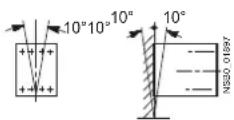
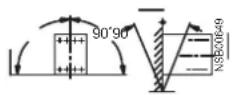
Vertical mounting Horizontal mounting
NOTICE
The permissible switching frequency values can vary according to the selected mounting position. For information about factors and how to determine the new switching frequency, refer to chapter Configuration [Page 73].
Note
An optional fan can be ordered for the 3RW40 24 to 3RW40 47 sizes; this fan is integrated in the device for 3RW40 55 to 3RW40 76. The 3RW30 cannot be equipped with a fan.
7.1 Installing the soft starter
7.1.3 Mounting dimensions, clearances, and assembly type
The minimum clearances from other devices must be complied with to ensure unobstructed cooling as well as the free supply and discharge of air to and from the heat sink.
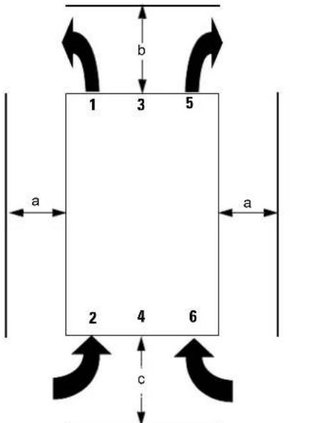
Figure 7-1 Clearances from other devices
| MLFB a (mm) a (in) b (mm) b | (in) c (mm) c (in) | ||||
| 3RW30 1./3RW30 2. 15 0.59 60 | 2.36 40 1.56 | ||||
| 3RW30 3./3RW30 4 30 1.18 60 | 2.36 40 1.56 | ||||
| 3RW40 2. 15 0.59 60 2.36 40 | 1.56 | ||||
| 3RW40 3./3RW40 4. 30 1.18 60 | 2.36 40 1.56 | ||||
| 3RW40 5./3RW40 7. | 5 | 0.2 | 100 | 4 | 75 |
NOTICE
Allow sufficient clearances for the cooling air to circulate freely. The device is ventilated from bottom to top.
7.1.4 Assembly type: Standalone assembly, side-by-side assembly, direct mounting
Standalone assembly
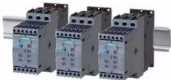
natural_image
Four identical electrical contactor units with no visible text or symbols on the device body.The term "standalone assembly" is used if the clearances a / b / c described in chapter Mounting dimensions, clearances, and assembly type [Page 54] are complied with.
Side-by-side assembly
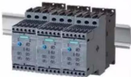
natural_image
Three identical electrical contactor blocks with blue and gray buttons, no visible text or symbolsThe term "side-by-side assembly" is used if the lateral clearance a described in chapter Mounting dimensions, clearances, and assembly type [Page 54] are not complied with, e.g. if several switching devices are assembled side by side.
7.1 Installing the soft starter
Direct mounting
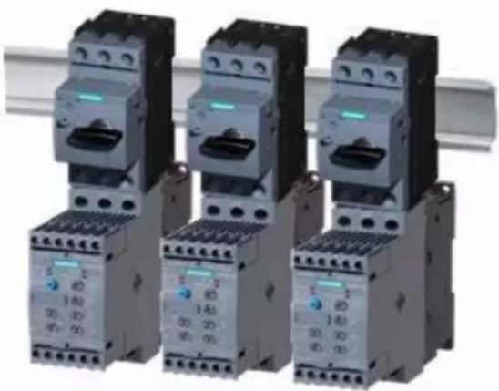
natural_image
Three identical electrical contactor units with varying sizes and terminal numbers, arranged side by side (no visible text or symbols)The term "direct mounting" is used if the top clearance b described in chapter Mounting dimensions, clearances, and assembly type [Page 54] is not complied with, e.g. if the soft starter is mounted directly on a motor starter protector (e.g. 3RV2) using a link module (e.g. 3RV29).
NOTICE
The permissible switching frequency values can vary according to the selected assembly type. For information about factors and how to determine the new switching frequency, refer to chapter Configuration [Page 73].
7.1.5 Installation requirements
Degree of protection IP00
The SIRIUS 3RW30 / 3RW40 soft starters conform to the IP00 degree of protection.
The devices must be installed in control cabinets with the IP54 degree of protection (pollution degree 2), taking account of the ambient conditions.
Make sure no liquids, dust, or conductive objects can get inside the soft starter. The soft starter produces waste heat (power loss) while it is operating (refer to chapter technical data [Page 121]).
CAUTION
Provide adequate cooling at the place of installation to prevent the switching device from overheating.
8.1 General information
General information
A motor feeder comprises a disconnector, a contact, and a motor as a minimum.
Line protection against short-circuits must be implemented, together with overload protection for the line and motor.
Disconnector
The isolating function with line protection against overload and short-circuits can be achieved with a motor starter protector or a fuse disconnector, for instance. The motor overload protection function is integrated in the SIRIUS 3RW40 soft starter. The motor overload protection for the SIRIUS 3RW30 soft starter can be implemented with a motor circuit breaker, for instance, or using a motor overload relay in conjunction with a contactor (for the fuse and motor starter protector assignment, refer to Technical data [Page 121]).
Contact
The contact function is taken care of by the SIRIUS 3RW30 or 3RW40 soft starter.

DANGER
Hazardous voltage
Danger of death or serious injury.
If mains voltage is present at the input terminals of the soft starter, hazardous voltage may still be present at the soft starter output even if a start command has not been issued. This voltage must be isolated by means of a disconnector (open isolating distance, e.g. with an open switch disconnector) whenever work is carried out on the feeder (refer to chapter Five safety rules for work in or on electrical systems [Page 58]).
Note
All elements of the main circuit (such as fuses, motor starter protectors, and switching devices) must be dimensioned for direct starting and according to the on-site short-circuit conditions, and ordered separately.
For recommended fuse and motor starter protector ratings for the feeder with soft starter, refer to chapter Technical data [Page 121].
8.2 Five safety rules for work in or on electrical systems
A set of rules, which are summarized in DIN VDE 0105 as the "five safety rules", are defined for work in or on electrical systems as a preventative measure against electrical accidents:
- Isolate
- Secure against switching on again
- Verify that the equipment is not live
- Ground and short-circuit
- Erect barriers around or cover adjacent live parts
These five safety rules must be applied in the above order prior to starting work on an electrical system. After completing the work, proceed in the reverse order.
It is assumed that every electrician is familiar with these rules.
Explanations
- The isolating distances between live and deenergized parts of the system must vary according to the operating voltage that is applied.
"Isolate" refers to the all-pole disconnection of live parts.
All-pole disconnection can be achieved, e.g. by.:
- Switching off the miniature circuit breaker
- Switching off the motor circuit breaker
- Unscrewing fusible links
-
Removing LV HRC fuses
-
The feeder must be secured against inadvertent restarting to ensure that it remains isolated for the duration of the work. This can be achieved, for instance, by securing the motor and miniature circuit breakers with lockable blocking elements in the disconnected state, either using a lock or by unscrewing the fuses.
- The deenergized state of the equipment should be verified using suitable test equipment, e.g. a two-pole voltmeter. Single-pole test pins are not suitable for this purpose. The absence of power must be established for all poles, phase to phase, and phase to N/PE.
- Grounding and short-circuiting are only mandatory if the system has a nominal voltage greater than 1 kV. In this case, the system should always be grounded first and then connected to the live parts to be short-circuited.
- These parts should be covered, or barriers erected around them, to avoid accidental contact during the work with adjacent parts that are still live.
8.3 General feeder assembly (type of coordination 1)
The SIRIUS 3RW30 or 3RW40 soft starter is connected into the motor feeder between the motor starter protector and the motor.
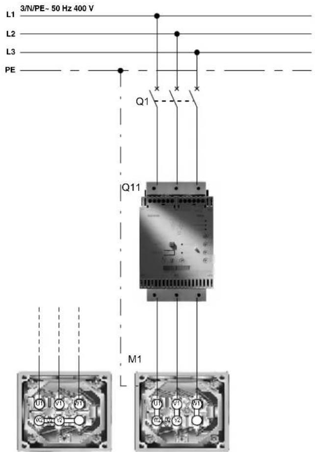
Figure 8-1 Block diagram of the SIRIUS 3RW40 soft starter
Note
For the component design, refer to chapter Technical data [Page 12].
8.4 Soft starter with line contactor (type of coordination 1)
8.4 Soft starter with line contactor (type of coordination 1)
If electrical isolation is specified, you can install a motor contactor between the soft starter and the motor starter protector.
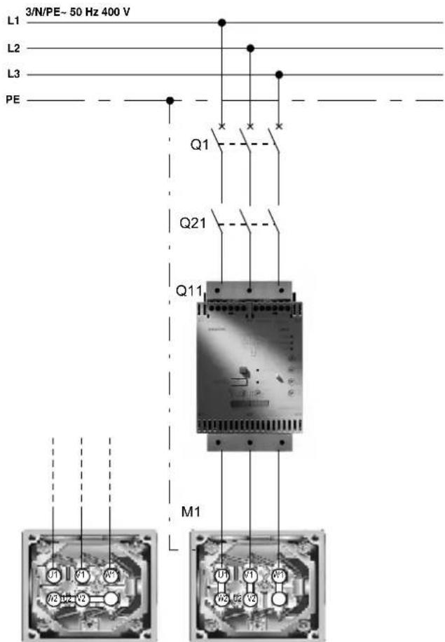
Figure 8-2 Block diagram of a feeder with an optional main / line contactor
Note
For the component design, refer to chapter Technical data [Page 121].
NOTICE
If a main or line contactor is used, it should not be connected between the soft starter and the motor. The soft starter could otherwise indicate a "Missing load voltage" fault in case of a start command and delayed connection of the contactor.
8.5 Soft starter assembly with type of coordination 2
The SIRIUS 3RW40 soft starter has internal protection to prevent overloading of the thyristors. The SIRIUS 3RW30 soft starter has no internal protection to prevent overloading of the thyristors. The soft starter must always be dimensioned according to the duration of the startup process and the desired starting frequency. If the feeder of the SIRIUS 3RW30 or 3RW40 soft starter is assembled accordingly with the feeder components recommended in chapter [Technical data [Page 121] (e.g. motor starter protector or LV HRC fuse), type of coordination 1 is achieved. In order to achieve type of coordination 2, all thyristors must be additionally protected against short-circuits by means of special semiconductor fuses (e.g. SIEMENS SITOR). A short-circuit can occur, for instance, as a result of a defect in the motor windings or in the motor's power supply cable.
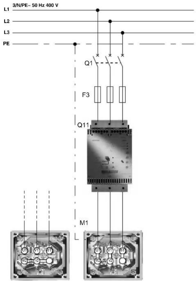
Figure 8-3 Block diagram of a feeder with semiconductor fuses
Note
For the component design, refer to chapter Technical data [Page 12].
8.6 Capacitors to improve the power factor
Note
Minimum and maximum configuration of the semiconductor fuses
The fuses for the minimum and maximum configuration are specified in chapter Technical data [Page 121].
Minimum configuration: The fuse is optimized for the thyristor's I²t value.
If the thyristor is cold (ambient temperature) and the startup process lasts a maximum of 20 s at 3.5 times the rated current of the device, the fuse does not trip.
Maximum configuration: The maximum current permitted for the thyristor can flow without the fuse tripping.
The maximum configuration is recommended for heavy-duty starting.
CAUTION
Risk of property damage
Type of coordination 1 in accordance with IEC 60947-4-1:
The device is defective following a short-circuit failure and therefore unsuitable for further use (personnel and equipment must not be put at risk).
Type of coordination 2 in accordance with IEC 60947-4-1:
The device is suitable for further use following a short-circuit failure (personnel and equipment must not be put at risk).
The type of coordination only refers to soft starters in conjunction with the stipulated protective device (motor starter protector / fuse), not to additional components in the feeder.
8.6 Capacitors to improve the power factor

CAUTION
No capacitors must be connected to the output terminals of the soft starter. If so, the soft starter will be damaged.
Active filters, e.g. for power factor correction, must not be operated parallel to the motor control device.
If capacitors are to be used to correct the power factor, they must be connected on the device's line side. If an isolating or main contactor is used together with the electronic soft starter, the capacitors must be disconnected from the soft starter when the contactor is open.
8.7 Maximum cable length
The cable between the soft starter and the motor must not be more than 300 m long (3RW30 and 3RW40).
The voltage drop due to the length of the cable to the motor may need to be considered when dimensioning the cable.
Cable lengths up to 500 m are permitted for SIRIUS 3RW44 soft starters (refer to the 3RW44 System Manual (http://support.automation.siemens.com/WW/ llisapi.dll?query=3RW44&func=cslib.cssearch&content=skm%2f-main.asp&lang=de&siteid=csius&objaction=cssearch&searchinprim=0&nodeid0=20025979)).
Connecting
9.1 Electrical connection
9.1.1 Control and auxiliary terminals
The SIRIUS 3RW30 and 3RW40 soft starters can be supplied with two different connection technologies:
- Screw-type technology
• Spring-loaded technology
9.1.2 Main circuit connection
SIRIUS 3RW30 and 3RW40 soft starters up to the 55 kW / 75 hp size at 400 V / 480 V are designed with removable terminals at the main circuit connections.
9.1 Electrical connection
Sizes 3RW30 1. to 3RW30 4.
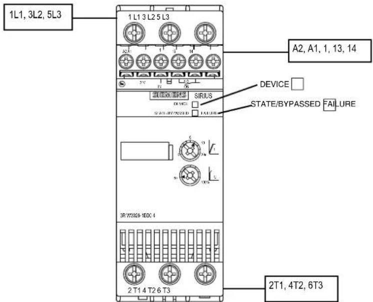
Sizes 3RW40 2. to 3RW40 4.
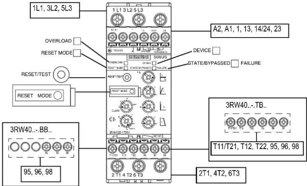
Sizes 3RW40 5. and 3RW40 7.
Sizes 3RW40 5. and 3RW40 7. have busbar connections for the main circuit connection. Box terminals can be retrofitted on these devices as optional accessories (refer to chapter Accessories [Page 199]).
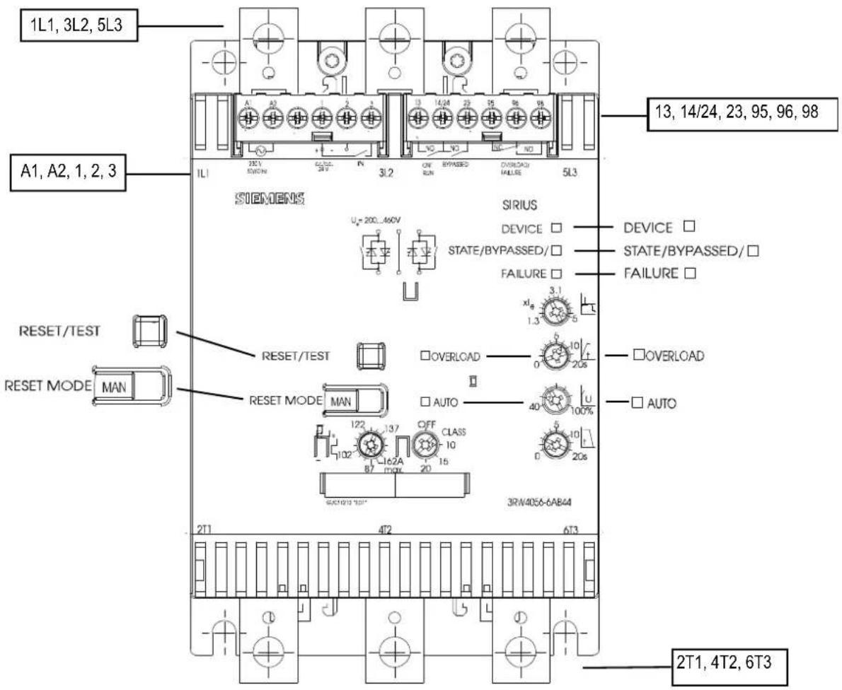
10.1 Operator controls, displays, and connections on the 3RW30
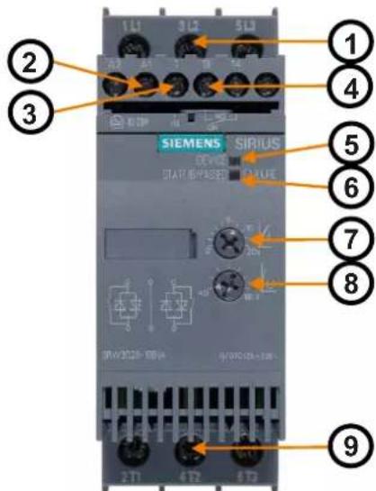
1 Operating voltage (three-phase mains voltage)
2 Control supply voltage
3 IN start input
4 ON output
5 DEVICE status LED
6 STATE / BYPASSED / FAILURE status LED
7 Ramp-up time
8 Starting voltage
9 Motor terminals
10.2 Operator controls, displays, and connections on the 3RW40
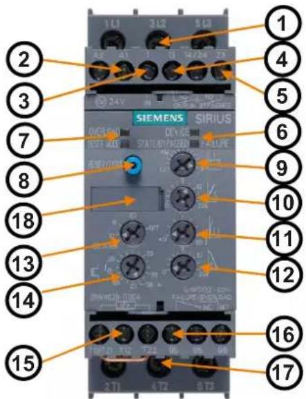
1 Operating voltage (three-phase mains voltage)
2 Control supply voltage
3 IN start input
4 ON / RUN output
5 BYPASSED output
6 DEVICE / STATE / BYPASSED / FAILURE status LEDs
7 OVERLOAD, RESET MODE status LEDs
8 TEST / RESET button
9 Current limiting
10 Ramp-up time
11 Starting voltage
12 Ramp-down time
13 Trip class
14 Motor current
16 Fault output
17 Motor terminals
15 Thermistor input (can be optionally ordered with 24 V AC/DC control voltage for 3RW40 2. to 3RW40 4. devices)
18 RESET MODE button (behind the label on the 3RW40 2., refer to the diagram below)
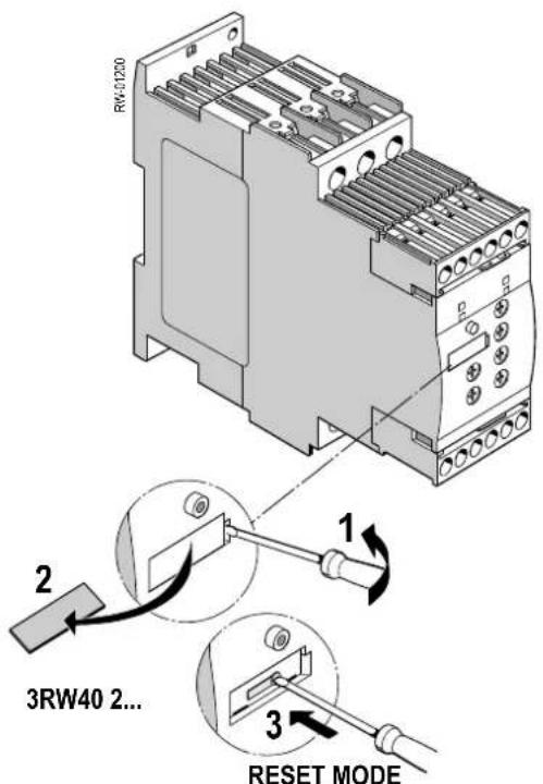
Figure 10-1 Button for setting RESET MODE behind the label
10.2 Operator controls, displays, and connections on the 3RW40
11.1 Configuration in general
The SIRIUS 3RW30 and 3RW40 electronic soft starters are designed for normal starting. A larger size may need to be selected for longer ramp-up times or a higher starting frequency.
An appropriately dimensioned SIRIUS 3RW40 or 3RW44 soft starter should be chosen for startup processes with motor ramp-up times >20 s.
The motor feeder between the soft starter and motor must not contain any capacitive elements (such as compensation systems). Active filters must not be operated in combination with soft starters.
All elements of the main circuit (such as fuses and switching devices) must be dimensioned for direct starting and according to the on-site short-circuit conditions, and ordered separately.
The harmonic component load of the starting current must be taken into consideration when selecting motor starter protectors (trip selection).
Note
Voltage dips generally occur in all start modes (direct starting, wye-delta starting, soft starting) when a three-phase motor is switched on. The infeed transformer must always be dimensioned so that the voltage dip at the motor startup remains within the permissible tolerance. If the infeed transformer is insufficiently dimensioned, the control voltage should be supplied from a separate circuit (independently of the main voltage) in order to prevent the voltage dip from disconnecting the 3RW.
Note
All elements of the main circuit (such as fuses, motor starter protectors, and switching devices) must be dimensioned for direct starting and according to the on-site short-circuit conditions, and ordered separately.
If wye-delta starters are exchanged for soft starters in an existing system, you should check the fuse ratings in the feeder in order to avoid false tripping. This is particularly important in connection with heavy-duty starting or if the fuse that is installed has already been operated close to the thermal tripping limit with the wye-delta assembly.
For recommended fuse and motor starter protector ratings for the feeder with soft starter, refer to chapter Technical data [Page 121].
11.1.1 Configuration procedure
- Select the correct starter
What application must be started and what functionality must be provided by the soft starter?
Chapter Selecting the optimum soft starter [Page 74] - Take account of the startup class and the switching frequency
Chapters Startup class [Page 76] and Calculating the permissible switching frequency [Page 81]
11.1 Configuration in general
- Take account of a possible reduction in the soft starter's rated data due to the ambient conditions and the type of assembly.
Chapter Reducing the rated data [Page 80]
11.1.2 Selecting the optimum soft starter
Selection aid
You can choose the optimum starter from the soft starter types available based on the intended application or the required functionality.
| Normal starting (CLASS 10) applications | 3RW30 3RW40 3RW44 | ||||
| P | u | m | p | + | |
| Pump with special stop (against water hammer) - - + | |||||
| Heat pump + + + | |||||
| Hydraulic pump x + + | |||||
| Press | x + + | ||||
| Conveyor belt | x + + | ||||
| Roller conveyor x + + | |||||
| Conveyor worm | x + + | ||||
| Escalator | - + + | ||||
| Piston compressor | - + + | ||||
| Screw compressor | - + + | ||||
| Small fan^1) | - | + | + | ||
| Centrifugal blower | - + + | ||||
| Bow thruster | - + + | ||||
- Recommended soft starter
x Possible soft starter
1) Small fan: Mass inertia (centrifugal mass) of fan < 10 x mass inertia of motor
| Heavy-duty starting (CLASS 20) applications | 3RW30 3RW40 3RW44 |
| Agitator | - x + |
| Extruder | - x + |
| Turning machine | - x + |
| Milling machine | - x + |
- Recommended soft starter
x Possible soft starter
| Ultra-heavy-duty starting (CLASS 30) applications | 3RW30 3RW40 3RW44 | |||
| Large fan2) | - | - | + | |
| Circular saw / band saw -- + | ||||
| Centrifuge -- + | ||||
| M | i | | | | | - |
| Crusher -- + | ||||
- Recommended soft starter
2) Large fan: Mass inertia (centrifugal mass) of fan >= 10 x mass inertia of motor
Soft starter functions 3RW30 3RW40 3RW44
| Soft start function + + + | |||
| Soft stop function - + + | |||
| Integrated intrinsic device protection - + + | |||
| Integrated electronic motor overload protection - + + | |||
| Settable current limiting - + + | |||
| Special pump stop function | - - + | ||
| Braking in ramp-down | - - + | ||
| Settable breakaway torque | - - + | ||
| Communication via PROFIBUS (optional) | - - + | ||
| External operation and indication display (optional) | - - + | ||
| Soft Starter ES parameterization software | - | - | + |
| Special functions, e.g. measured values, display languages etc. | - | - | + |
| Motor overload protection acc. to ATEX | - + - | ||
- Recommended soft starter
Note
SIRIUS 3RW44 soft starter
For more information about the SIRIUS soft starter, refer to the 3RW44 System Manual. You can download (http://support.automation.siemens.com/WW/lllsapi.dll?func=cslib.csinfo&lang=de&objID=20356385&subtype=133300) the manual free of charge.
11.2 Startup class
11.2 Startup class
To achieve the optimum soft starter design, it is important to know and take into account the ramp-up time (startup class) of the application. Long ramp-up times mean a higher thermal load on the thyristors of the soft starter. An appropriately dimensioned SIRIUS 3RW40 or 3RW44 soft starter should be chosen for startup processes with a motor ramp-up time >20 s. The maximum permissible ramp-up time for SIRIUS 3RW30 soft starters is 20 seconds. SIRIUS soft starters are designed for continuous operation with normal starting (CLASS 10), an ambient temperature of 40 °C, and a defined switching frequency (refer to chapter Technical data [Page 121]). If other data applies, the starters may need to be calculated with a size allowance. Using the SIEMENS Win-Soft Starter selection and simulation software, you can enter your application data and requirements to obtain an optimally dimensioned soft starter (refer to chapter Win-Soft Starter selection and simulation software [Page 162]).
CAUTION
Risk of property damage
When using the 3RW30: Make sure the selected ramp time is longer than the actual motor ramp-up time. If not, the SIRIUS 3RW30 may be damaged because the internal bypass contacts close when the set ramp time elapses. If the motor has not finished starting up, an AC3 current that could damage the bypass contact system will flow.
When using the 3RW40: The 3RW40 has an integrated ramp-up detection function that prevents this operating state from occurring.
Selection criteria
Note
You must select the size of your SIRIUS soft starters according to the rated motor current (rated current _soft starter >= rated motor current).
11.2.1 Application examples for normal starting (CLASS 10) with 3RW30 and 3RW40
Recommended basic parameter settings
Assuming the conditions and constraints indicated below apply, the size of the soft starters can be equivalent to the motor rating for a normal starting characteristic (CLASS 10).
You can find a suitable soft starter for the required motor rating based on the required startup class in chapter Technical data [Page 121].
For typical applications where normal starting applies as well as recommended parameter settings for the soft starter, refer to the table below.
Normal starting (CLASS 10)
The soft starter rating can be equivalent to the motor rating.
| Application | Conveyor belt | Roller conveyor | Compressor | 1) | PumpSmall fanheat / hydraulic pump | ||
| Start parameters | |||||||
| • Voltage ramp and current limiting | |||||||
| - Starting voltage | % | 70 | 60 | 50 | 40 | 40 | 40 |
| - Ramp-up time | s | 10 | 10 | 10 | 10 | 10 | 10 |
| - Current limiting value (3RW40) | Off (5 x I_M ) | Off (5 x I_M ) | 4 x I_M | 4 x I_M | 4 x I_M | 4 x I_M | |
| Stop mode | Soft stop(3RW40 only) | Soft stop(3RW40 only) | Stop without load | Stop without load | (3RW40 only) | Stop without loadSoft stop | |
1) Small fan: Mass inertia (centrifugal mass) of fan < 10 x mass inertia of motor
| General conditions and constraints | |
| CLASS 10 (normal starting) | |
| 3RW30: Maximum ramp-up time 3 s, 300 % starting current, 20 starts / hour | |
| 3RW40: Maximum ramp-up time 10 s, 300 % current limiting, 5 starts / hour | |
| ON time 30 % | |
| Standalone assembly | |
| Installation altitude Max. 1000 m / 3280 ft | |
| Ambient temperature kW 40 °C / 104 °F | |
11.2 Startup class
11.2.2 Application examples for heavy-duty starting (CLASS 20): 3RW40 only
Recommended basic parameter settings
Assuming the conditions and constraints indicated below apply, the soft starter size must be at least one power class higher than the motor rating for heavy-duty starting (CLASS 20).
You can find a suitable soft starter for the required motor rating based on the required startup class in chapter Technical data [Page 121].
For typical applications where heavy-duty starting can apply as well as recommended parameter settings for the soft starter, refer to the table below.
Heavy-duty starting (CLASS 20)
The soft starter must be at least one power class larger than the motor rating.
| Application | Agitator | Extruder | Milling machine | |
| Start parameters | ||||
| • Voltage ramp and current limiting | ||||
| - Starting voltage | % | 40 | 70 | 40 |
| - Ramp-up time | s | 20 | 10 | 20 |
| - Current limiting value (3RW40) | 4 × I_M | Off ( 5 × I_M ) | 4 × I_M | |
| Stop mode | Stop without load | Stop without load | Stop without load | |
| General conditions and constraints | |
| CLASS 20 (heavy-duty starting) | |
| 3RW40 2. / 3RW40 3. / 3RW40 4. Maximum ramp-up time 20 s,300 % current limiting,max. 5 starts / hour | |
| 3RW40 5. / 3RW40 7. Maximum ramp-up time 40 s,350 % current limiting,max. 1 start / hour | |
| ON time 30 % | |
| Standalone assembly | |
| Installation altitude Max. 1000 m / 3280 ft | |
| Ambient temperature kW 40 °C / 104 °F | |
Note
The settings and device dimensions indicated in these tables are examples only; they are merely provided for information purposes and are not binding. The actual settings depend on the application and must be optimized when the equipment is commissioned.
If other conditions and constraints apply, either refer to chapter Technical data [Page 121] or check your requirements and selection with the Win-Soft Starter software or with Technical Assistance (chapter Important notes [Page 11])
11.3 ON time and switching frequency
Based on the rated motor current and the startup class, the SIRIUS 3RW30 and 3RW40 soft starters are dimensioned for a maximum permissible switching frequency in combination with a relative ON time (refer to chapter technical data [Page 121]). If these values are exceeded, a larger soft starter may have to be selected.
ON time
The relative ON time in % is the ratio between the load duration and the cycle duration for loads that are frequently switched on and off.
The ON time (OT) can be calculated using the following formula:
$$ O T = \frac {t _ {s} + t _ {b}}{t _ {s} + t _ {b} + t _ {p}} $$
where:
$$ \mathrm{OT} = \text { ON time } [ \% ] $$
$$ t _ {s} = \text { ramp - up time } [ s ] $$
$$ \mathbf {t _ {b}} = \text { operating time } [ s ] $$
$$ t _ {p} = \text { idle time } [ s ] $$
The following diagram illustrates this process.
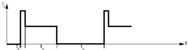
line
| t | I_s | |-------|-----| | t_s | 0 | | t_b | 1 | | t_p | 0 | | t_p | 2 |Figure 11-1 ON time
Switching frequency
The maximum permissible switching frequency must not be exceeded because the devices could be damaged due to thermal overloading.
Optional additional fan
The switching frequency of the 3RW40 2. to 3RW40 4. soft starters can be increased by installing an optional additional fan. For information about factors and how to determine the maximum switching frequency if an additional fan is installed, refer to chapter Calculating the permissible switching frequency [Page 81].
11.4 Reducing the rated data
11.4 Reducing the rated data
You can reduce the rated data of the SIRIUS 3RW30 and 3RW40 soft starters if
- The installation altitude is higher than 1000 m.
- The ambient temperature in the switching device's environment exceeds 40^ .
- The lateral clearances described earlier are not complied with, e.g. side-by-side assembly or direct mounting of other switching devices (assembly type).
- The vertical mounting position is not complied with.
11.5 Installation altitude and ambient temperature
Installation altitude
The permissible installation altitude must not be higher than 5000 m above sea level (higher than 5000 m on request).
If the installation altitude exceeds 1000 m, the rated operational current must be reduced for thermal reasons.
If the installation altitude exceeds 2000 m, the rated voltage must also be reduced owing to the restricted dielectric strength. A maximum permissible rated voltage of 460 V applies at installation altitudes between 2000 m and 5000 m above sea level.
The following diagram shows the reduction in the rated device current as a function of the installation altitude:
The rated operational current I_e must be reduced at altitudes higher than 1000 m above sea level.

line
| Mounting height in m | Rated operational current Ie in % | | -------------------- | --------------------------------- | | 0 | 100 | | 2000 | 100 | | 3000 | 98 | | 4000 | 94 | | 5000 | 90 | | 6000 | 85 | | 7000 | 80 | | 8000 | 75 | | 9000 | 72 |Figure 11-2 Reduction as a function of the installation altitude
Ambient temperature
The maximum permissible ambient temperature of the soft starter must not exceed 60 °C .
SIRIUS 3RW30 and 3RW40 soft starters are designed for operation with nominal current at an ambient temperature of 40 °C. If this temperature is exceeded, e.g. owing to an impermissible temperature rise in the control cabinet, other loads, or a general increase in the ambient temperature, the resulting deterioration in the soft starter's performance must be
11.6 Calculating the permissible switching frequency
taken into account when the device is dimensioned (refer to chapter Technical data [Page 121]).
CAUTION
Risk of property damage.
The soft starter may be damaged if the maximum installation altitude (5000 m above sea level) or an ambient temperature of 60 °C is ignored.
Mounting position, assembly type
The mounting position and assembly type (refer to chapter Installing the soft starter [Page 53]) can influence the soft starter's permissible switching frequency. Refer to chapter Calculating the permissible switching frequency [Page 81] for the permissible mounting and assembly combinations as well as the resulting factors for the soft starter switching frequencies.
11.6 Calculating the permissible switching frequency
11.6.1 Table of permissible assembly combinations with switching frequency factors
The factors indicated in the table refer to the switching frequency (starts / hour) as specified in chapter [Technical data [Page 121].
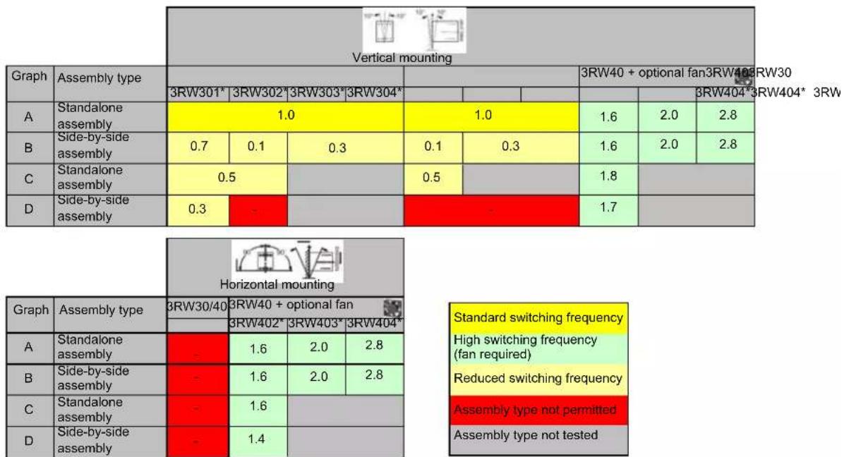
other
| Category | Assembly Type | Vertical Mounting | |---|---|---| | Graph | Assembly type | 3RW301* | | A | Standalone assembly | 1.0 | | B | Side-by-side assembly | 0.7 | | C | Standalone assembly | 0.5 | | D | Side-by-side assembly | 0.3 | Horizontal Mounting Horizontal mounting Horizontal mountings Standard switching frequency High switching frequency (fan required) Reduced switching frequency Assembly type not permitted Assembly type not tested11.6 Calculating the permissible switching frequency
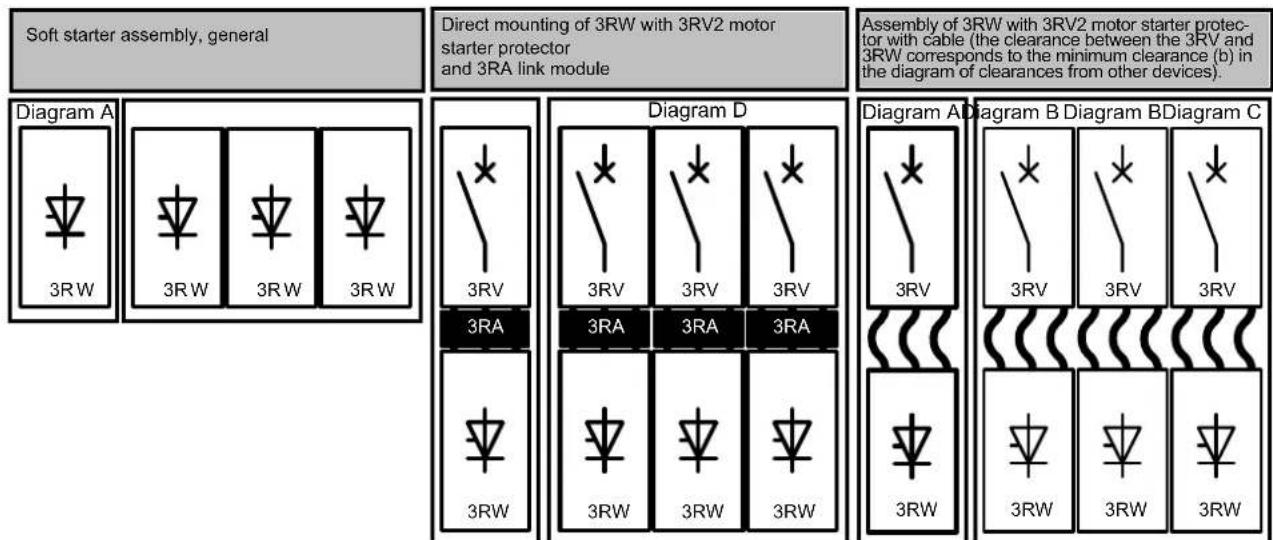
flowchart
graph TD
    subgraph_Diagram_A["Diagram A"]
        A1["3RW"] --> A2["3RW"]
        A2 --> A3["3RW"]
        A3 --> A4["3RW"]
    end

    subgraph_Diagram_D["Diagram D"]
        D1["3RV"] --> D2["3RA"]
        D2 --> D3["3RW"]
        D3 --> D4["3RW"]
        D4 --> D5["3RW"]
        D5 --> D6["3RW"]
    end

    subgraph_Diagram_B["Diagram B"]
        B1["3RV"] --> B2["3RV"]
        B2 --> B3["3RV"]
        B3 --> B4["3RW"]
        B4 --> B5["3RW"]
        B5 --> B6["3RW"]
    end

    subgraph_Diagram_C["Diagram C"]
        C1["3RV"] --> C2["3RW"]
        C2 --> C3["3RW"]
        C3 --> C4["3RW"]
        C4 --> C5["3RW"]
    end

    A1 --> A2 --> A3 --> A4 --> A5 --> A6 --> A7 --> A8 --> A9 --> A10 --> A11 --> A12 --> A13 --> A14 --> A15 --> A16 --> A17 --> A18 --> A19 --> A20 --> A21 --> A22 --> A23 --> A24 --> A25 --> A26 --> A27 --> A28 --> A29 --> A30 --> A31 --> A32 --> A33 --> A34 --> A35 --> A36 --> A37 --> A38 --> A39 --> A40 --> A41 --> A42 --> A43 --> A44 --> A45 --> A46 --> A47 --> A48 --> A49 --> A50 --> A51 --> A52 --> A53 --> A54 --> A55 --> A56 --> A57 --> A58 --> A59 --> A60 --> A61 --> A62 --> A63 --> A64 --> A65 --> A66 --> A67 --> A68 --> A69 --> A70 --> A71 --> A72 --> A73 --> A74 --> A75 --> A76 --> A77 --> A78 --> A79 --> A80
    end

    style Diagram A fill:#f9f,stroke:#333
    style Diagram D fill:#ccf,stroke:#333
    style Diagram B fill:#cfc,stroke:#333
    style Diagram C fill:#fcc,stroke:#333
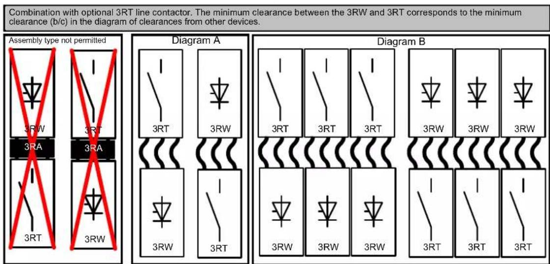
Assembly of 3RW with 3RV2 motor starter protector, 3RA link module, cable, and 3RT line contactor. The minimum clearance between the 3RW, 3RV, and 3RT corresponds to the minimum clearance (b/c) in the diagram of clearances from other devices.
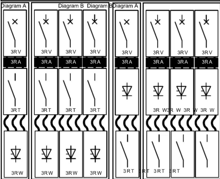
Assembly of 3RW with 3RV2 motor starter protector and 3RT line contactor with cable. The minimum clearance between the 3RV and 3RT corresponds to the minimum clearance (b/c) in the diagram of clearances from other devices.
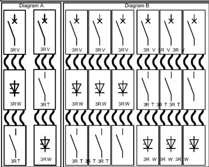
11.6 Calculating the permissible switching frequency
| MLFB a (mm) a (in) b | (mm) b (in) c (mm) c (in) | ||||||
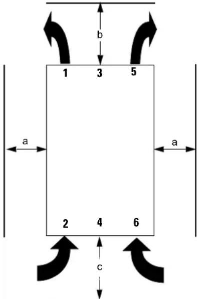 Figure 11-3 Clearances from other devices Figure 11-3 Clearances from other devices | 3RW30 1./3RW30 2. 15 | 0.59 | 60 | 2.36 40 | 1.56 | ||
| 3RW30 3./3RW30 4 30 | 1.18 | 60 | 2.36 40 | 1.56 | |||
| 3RW40 2. 15 0.59 60 2 | .36 | 40 | 1.56 | ||||
| 3RW40 3./3RW40 4. 30 | 1.18 | 60 | 2.36 40 | 1.56 | |||
| 3RW40 5./3RW40 7. 5 | 0.2 | 100 | 4 | 75 | 3 | ||
11.6.2 Calculating the switching frequency (example)
Problem
The maximum permissible switching frequency of a 5.5 kW (12.5 A) 3RW4024 soft starter must be determined. The requirements are side-by-side assembly and vertical mounting. A ramp-up time of approx. 3 s at an ambient temperature of 40 °C is specified as a supplementary condition (e.g. a pump motor with CLASS 10 starting). The soft starter must be connected to a 3RV2021 motor starter protector by means of cables. (Clearance between 3RV and 3RW >= 40 mm)
Calculating the number of starts / hour of a 3RW40 for side-by-side assembly and vertical mounting
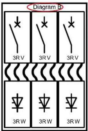
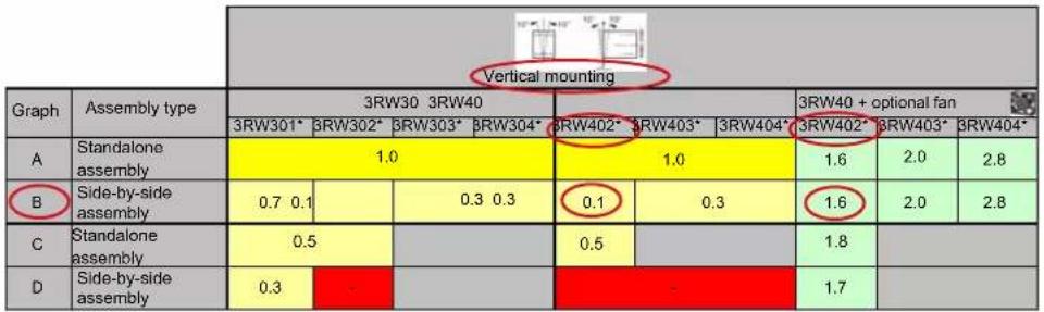
| Type | 3RW4024 | |
| Power electronics | ||
| Load rating with rated operational current I_e According to IEC and UL/CSA ^1) ,for standalone assembly,AC-53a | ||
| - At 40°C | A | 12.5 |
| - At 50°C | A | 11 |
| - At 60°C | A | 10 |
| Minimum settable rated motor current I_M for the motor overload protection | A | 5 |
| Power loss | ||
| - During operation after successful startup with uninterrupted rated operational current (40°C) approx. | W | 2 |
| - During starting with current limit set to 300% I_M( 40^ C) | W | 68 |
| Permissible rated motor current and starts per hour | ||
| - For normal starting (CLASS 10) - Rated motor current I_M^2) ,ramp-up time 3 s - Starts per hour ^3) | A | 12.5 |
| 1/h | 50 | |
Assembly of a 3RV2021 motor starter protector and connection of a 3RW40 24 soft starter with cables and vertical mounting for CLASS 10 starting:
Switching frequency of 3RW40 with standalone assembly: 50 1/h
Switching frequency factor for diagram B without a fan: 0.1
Switching frequency factor for diagram B with a fan 1): 1.6
Maximum permissible switching frequency:
Without fan 50 1/h x 0.1 = 5 1/h
With fan 1): 50 1/h x 1.6 = 80 1/h
1) Optional fan: 3RW49 28-8VB00
Result
The pump could be started five times an hour providing the above assembly conditions are complied with (side-by-side assembly, vertical mounting). A switching frequency of up to 80 starts per hour can be achieved by equipping the 3RW4026 with the optional 3RW4928-8VB00 fan.
11.7 Configuration aids
11.7 Configuration aids
11.7.1 Online configurator
Using the online configurator, you can select soft starters based on the rated motor data and the specified device functionality. The selection of the soft starter is subject to fixed conditions and constraints, such as switching frequency, startup class etc. These conditions cannot be changed. You can find the online configurator at www.siemens.de/sanftstarter (https://mall.automation.siemens.com/WW/guest/configurators/ipc/ipcFrameset.asp?serumpage=guilpc&urlParams=PROD%5FID%3D3RW&MLFB=&proxy=mall%2Eautomation%2Esiemens%2Ecom&retURL=%2FWW%2Fguest%2Findex%2Easp%3FnodeID%3D9990301%26lang%3Dde&lang=en).
11.7.2 Win-Soft Starter selection and simulation software
The Win-Soft Starter software can be used to simulate and select all SIEMENS soft starters, taking into account various parameters such as the supply system conditions, motor data, load data, high switching frequencies etc.
It is a useful tool, which does away with the need for time-consuming and complex manual calculations if you need to select the optimum soft starter for your particular case.
Further information under:
www.siemens.de/sanftstarter > software > Win-Soft Starter (http:// www.automation.siemens.com/mcms/low-voltage/en/industrial-controls/controls/solid-state-switching-devices/soft/software/win-soft-starter/Pages/default.aspx)
11.7.3 Technical Assistance
SIEMENS Technical Assistance offers personal support to help you find the optimum device and provides assistance with technical queries relating to low-voltage switchgear and controlgear
| Technical Assistance: | Phone: +49 (0) 911-895-5900 ( 8^ - 17^ CET) Fax: +49 (0) 911-895-5907e-mail: (mailto:technical-assistance@siemens.com)Internet: (www.siemens.com/lowvoltage/technical-assistance) |
11.7.4 SIRIUS soft starter training course (SD-SIRIUSO)
SIEMENS offers a two-day training course on SIRIUS electronic soft starters to keep both customers and our own employees up to date with the latest information about configuring, commissioning, and maintenance.
Please address all inquiries and enrollments to:
Training Center Erlangen
A&D PT 4
11.8 Order number system for the 3RW30
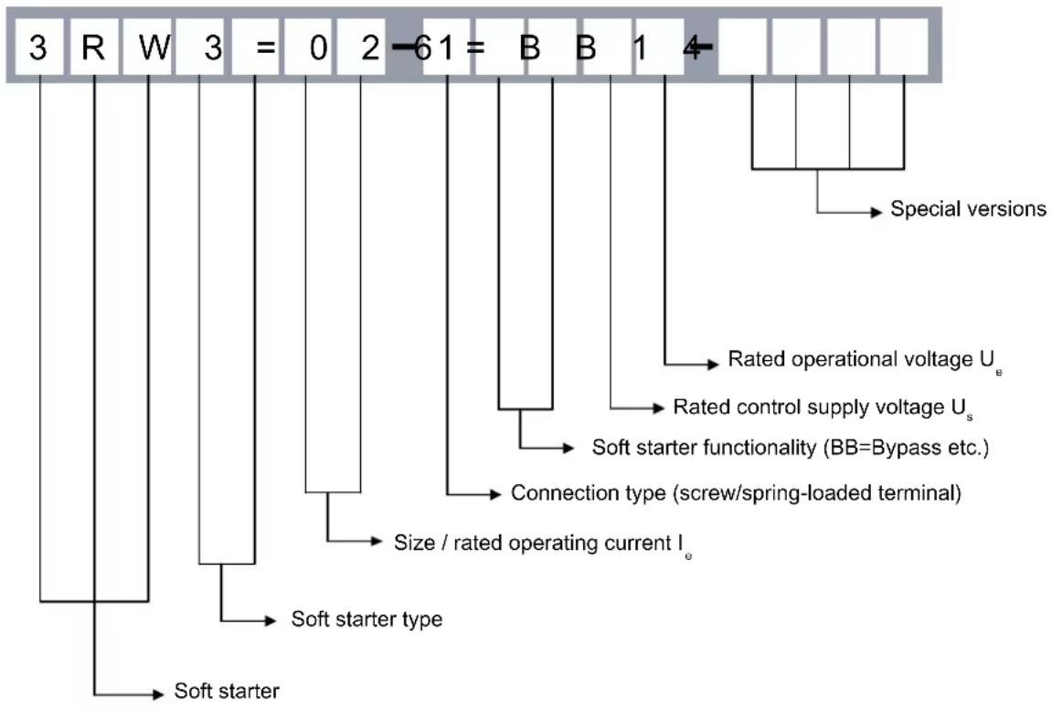
flowchart
graph TD
    A["Soft starter"] --> B["Soft starter type"]
    B --> C["Size / rated operating current I_e"]
    C --> D["Connection type (screw/spring-loaded terminal)"]
    D --> E["Soft starter functionality (BB=Bypass etc.)"]
    E --> F["Rated control supply voltage U_s"]
    F --> G["Rated operational voltage U_e"]
    G --> H["Special versions"]
    style A fill:#f9f,stroke:#333
    style H fill:#ccf,stroke:#333
Rated current and rated power at U_e=400 V/460 V and T_amb=40 ^/50 ^
| 13 le = 3.6 A / 3 A Pe = 1.5 kW / 1.5 hp Size S00 | ||
| 14 le = 6.5 A / 4.8 A Pe = 3 kW / 3 hp | ||
| 16 le = 9.0 A / 7.8 A Pe = 4 kW / 5 hp | ||
| 17 le = 12.5 A / 11 A | Pe = 5.5 kW / 7.5 hp | |
| 18 le = 17.6 A / 17 A | Pe = 7.5 kW / 10 hp | |
| 26 le = 25 A / 23 A | Pe = 11 kW / 15 hp | Size S0 |
| 27 le = 32 A / 29 A | Pe = 15 kW / 20 hp | |
| 28 le = 38 A / 34 A | Pe = 18.5 kW / 25 hp | |
| 36 le = 45 A / 42 A | Pe = 22 kW / 30 hp | Size S2 |
| 37 le = 63 A / 58 A | Pe = 30 kW / 40 hp | |
| 38 le = 72 A / 62 A | Pe = 37 kW / 40 hp | |
| 46 le = 80 A / 73 A | Pe = 45 kW / 50 hp | Size S3 |
| 47 le = 106 A / 398 A | Pe = 55 kW / 75 hp | |
For more information, refer to chapter Technical data [Page 121].
11.9 Order number system for the 3RW40
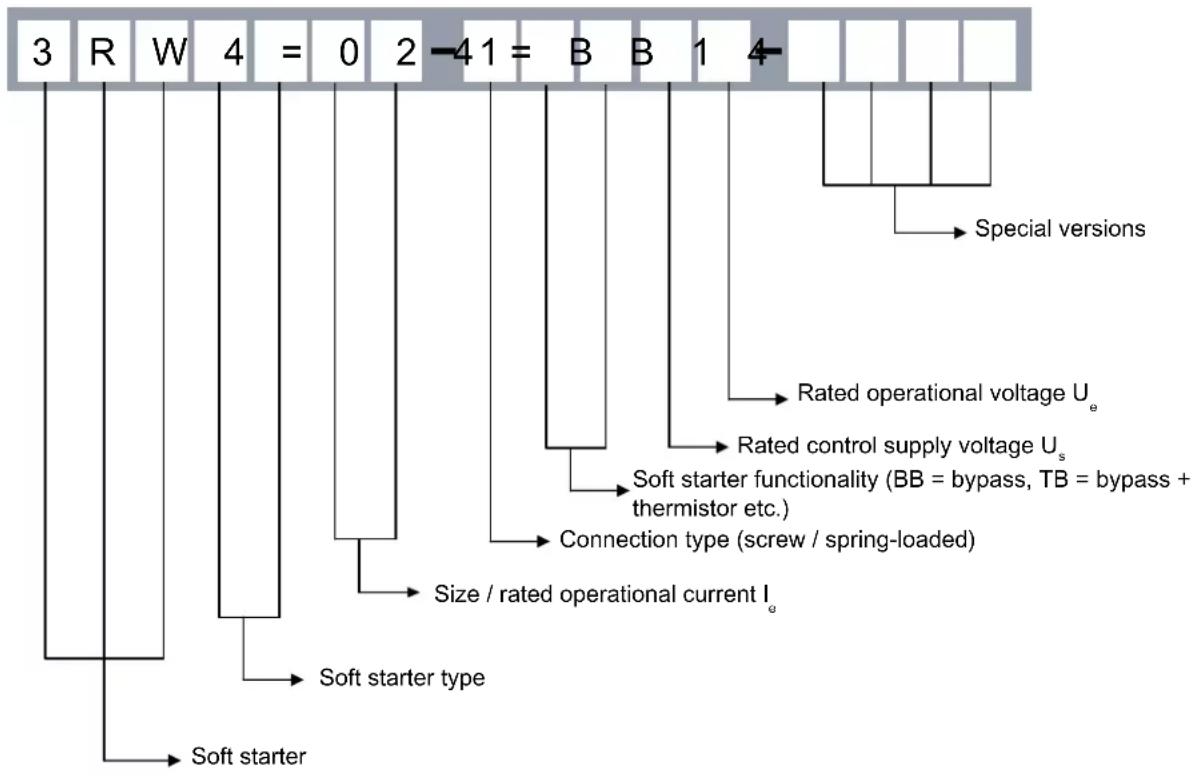
flowchart
graph TD
    A["3 R W 4 = 0 2 -41 = B B 1 4"] --> B["Soft starter"]
    C["Special versions"] --> D["Rated operational voltage Ue"]
    C --> E["Rated control supply voltage Us"]
    C --> F["Soft starter functionality (BB = bypass, TB = bypass + thermistor etc.)"]
    C --> G["Connection type (screw / spring-loaded)"]
    C --> H["Size / rated operational current Ie"]
    C --> I["Soft starter type"]
Rated current and rated power at U_e=400 V/460 V and T_amb=40 ^/50 ^
24 le = 12.5 A / 11 A Pe = 5.5 kW / 7.5 hp Size S0
26 le = 25 A / 23 A Pe = 11 kW / 15 hp
27 le = 32 A / 29 A Pe = 15 kW / 20 hp
28 le = 38 A / 34 A Pe = 18.5 kW / 25 hp
36 le = 45 A / 42 A Pe = 22 kW / 30 hp Size S2
37 le = 63 A / 58 A Pe = 30 kW / 40 hp
38 le = 72 A / 62 A Pe = 37 kW / 40 hp
46 le = 80 A / 73 A Pe = 45 kW / 50 hp Size S3
47 le = 106 A / 98 A Pe = 55 kW / 75 hp
55 le = 132 A / 117 A Pe = 75 kW / 75 hp Size S6
56 le = 160 A / 145 A Pe = 90 kW / 100 hp
73 le = 230 A / 205 A Pe = 132 kW / 150 hp Size S12
74 le = 280 A / 248 A Pe = 160 kW / 200 hp
75 le = 350 A / 315 A Pe = 200 kW / 250 hp
76 le = 432 A / 385 A Pe = 250 kW / 300 hp
For more information, refer to chapter Technical data [Page 121].
11.9 Order number system for the 3RW40
12.1 Before commencing work: Isolating the equipment from the supply system and ensuring that it cannot be reconnected.

DANGER
Hazardous voltage Will cause death or serious injury.
- Disconnect the system and all devices from the power supply before starting work.
- Secure against switching on again.
- Verify that the equipment is not live.
• Ground and short-circuit. - Erect barriers around or cover adjacent live parts.

DANGER
Hazardous voltage Will cause death or serious injury.
Qualified Personnel.
The equipment / system may only be commissioned and operated by qualified personnel. For the purpose of the safety information in these Operating Instructions, a "qualified person" is someone who is authorized to energize, ground, and tag equipment, systems, and circuits in accordance with established safety procedures.
12.2 Commissioning the 3RW30
12.2 Commissioning the 3RW30
Commissioning, description of the start and output parameters
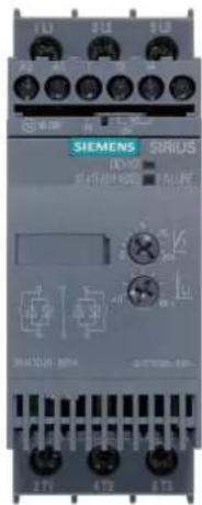
12.2.1 Commissioning procedure
- Check the voltages and wiring.
- Set the start parameters (for recommended parameters, refer to the quick commissioning table).
- Start up the motor and if necessary optimize the parameters (refer to the quick commissioning table).
- Document the parameter settings if required (refer to chapter Table of parameters used [Page 205]).
12.2.2 Quick commissioning of the 3RW30 and optimization of the parameters
CAUTION
Risk of property damage.
Connection to unassigned terminals is not permitted.
| Recommended setting | Start parameters | |
| Application | Starting voltage %  | Ramp time s  |
| Conveyor belt | 70 10 | |
| Roller conveyor | 60 10 | |
| Compressor | 50 20 | |
| Small fan | 40 20 | |
| Pump | 40 10 | |
| Hydraulic pump | 40 10 | |
| Agitator | 40 20 | |
CAUTION
Risk of property damage.
Take account of the switching frequency (refer to the technical data). The soft starter could be damaged if the switching frequency is too high.
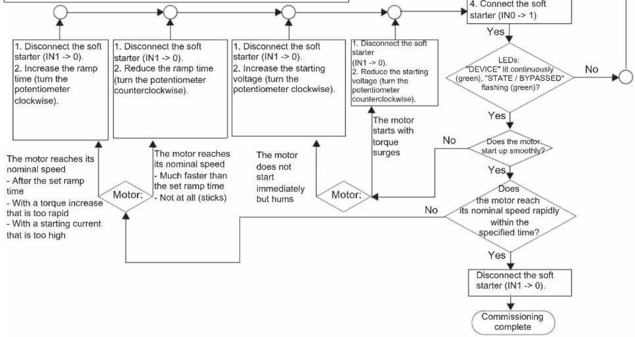
flowchart
graph TD
    A["1. Disconnect the soft starter (IN1 --> 0).\n2. Increase the ramp time (turn the potentiometer clockwise)."] --> B["Motor:"]
    C["1. Disconnect the soft starter (IN1 --> 0).\n2. Reduce the ramp time (turn the potentiometer counterclockwise)."] --> B
    D["1. Disconnect the soft starter (IN1 --> 0).\n2. Increase the starting voltage (turn the potentiometer clockwise)."] --> E["Motor:"]
    F["1. Disconnect the soft starter (IN1 --> 0).\n2. Reduce the starting voltage (turn the potentiometer counterclockwise)."] --> E
    G["4. Connect the soft starter (IN0 --> 1)"] --> H{LEDs: "DEVICE" lit continuously (green), "STATE / BYPASSED" flashing (green)?}
    H -->|No| I["Commissioning complete"]
    H -->|Yes| J{Does the motor start up smoothly?}
    J -->|No| K["Motor:"]
    J -->|Yes| L{Does the motor reach its nominal speed rapidly within the specified time?}
    L -->|No| M["Motor:"]
    L -->|Yes| N["Disconnect the soft starter (IN1 --> 0)."]
    N --> O["Commissioning complete"]
    P["The motor reaches its nominal speed\n- After the set ramp time\n- With a torque increase that is too rapid\n- With a starting current that is too high"] --> B
    P --> E
    Q["The motor reaches its nominal speed\n- Much faster than the set ramp time\n- Not at all (sticks)"] --> B
    R["The motor does not start immediately but hums"] --> E
12.2.3 Setting the soft start function
Voltage ramp
The SIRIUS 3RW30 achieves soft starting by means of a voltage ramp. The motor terminal voltage is increased from a parameterizable starting voltage to the mains voltage within a definable ramp time.
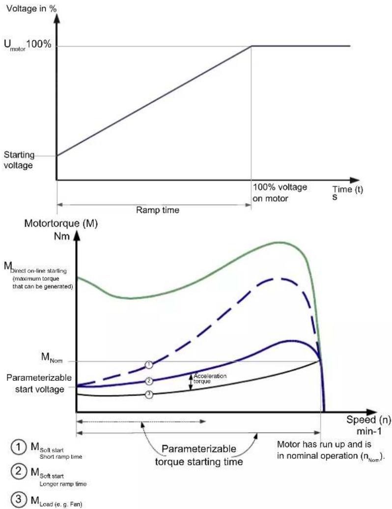
② M_Soft start Longer ramp time
③ M_Load (e.g. Fan)
12.2.4 Setting the starting voltage
U potentiometer
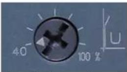
The starting voltage value is set with the U potentiometer. This value determines the starting torque of the motor. A lower starting voltage results in a lower starting torque (softer start) and a lower starting current.
The starting voltage selected must be sufficiently high to ensure that motor starts up smoothly as soon as the start command is received by the soft starter.
12.2.5 Setting the ramp time
t potentiometer
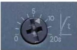
You define the length of the required ramp time with the t potentiometer. The ramp time determines the time taken to increase the motor voltage from the parameterized starting voltage to the mains voltage. This time merely influences the motor's acceleration torque, which drives the load during the ramp-up process. The actual motor starting times are load-dependent and can differ from the 3RW soft starter settings.
A longer ramp time results in a lower starting current and a reduced acceleration torque as the motor starts up. The startup is slower and smoother as a result. The ramp time must be long enough for the motor to reach its nominal speed. If the time selected is too short, in other words if the ramp time ends before the motor has started up successfully, a very high starting current that can even equal the direct starting current at the same speed occurs at this instant.
The SIRIUS 3RW30 soft starter can be damaged in this application (set ramp time shorter than the actual motor ramp-up time). A maximum ramp-up time of 20 s is possible for the 3RW30. An appropriately dimensioned SIRIUS 3RW40 or 3RW44 soft starter should be chosen for startup processes with a motor ramp-up time > 20 s.
CAUTION
Risk of property damage
Make sure the selected ramp time is longer than the actual motor ramp-up time. If not, the SIRIUS 3RW30 may be damaged because the internal bypass contacts close when the set ramp time elapses. If the motor has not finished starting up, an AC3 current that could damage the bypass contact system will flow.
When using the 3RW40: The 3RW40 has an integrated ramp-up detection function that prevents this operating state from occurring.
12.2.6 ON output
ON output contact
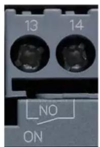
IN
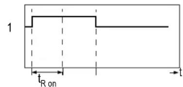
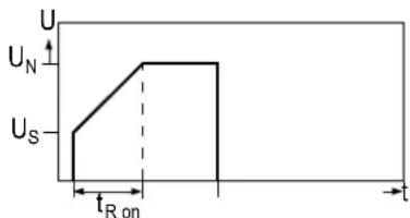
ON 13/14
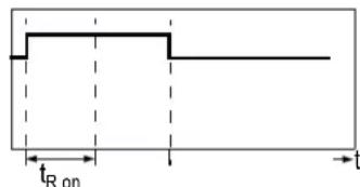
Figure 12-1 State diagram of the ON output contact
The output contact at terminal 13/14 (ON) closes if a signal is present at terminal 1 (IN); it remains closed until the start command is removed.
The output can be used, for instance, to control a line contactor connected upstream or to implement latching if you selected pushbutton control. For recommended circuits, refer to chapter Typical circuit diagrams [Page 167].
For the state diagram of the contacts in the various operating states, refer to chapter 3RW30: LEDs and troubleshooting [Page 44].
12.3 3RW30: LEDs and troubleshooting
| LEDs on 3RW30 | Auxiliary contact | |||
| Soft starter | ||||
| 3RW30 | DEVICE(rd/gn/ylw) | STATE/BYPASSED/FAILURE(gn/rd) | 13 14/(ON) | |
| U_S = 0 | ||||
| Operating state | IN | |||
| Off | 0 | |||
| Start | 1 | |||
| Bypassed | 1 | |||
| Fault | ||||
| Impermissible electronics supply voltage1) | ||||
| Bypass overload2) | ||||
| - Missing load voltage1)- Phase failure, missing load1) | ||||
| Device fault3) |


| LEDs | [322H] | ||||
| = | = | ylwrd gn | |||
| Off= | ON | Flashing | Green | =Red=Ye | low |
1) The fault is automatically reset by an outgoing event. An automatic restart is initiated and the 3RW restarted if a start command is present at the input.
| WARNING |
| Automatic restartDanger of death, serious injury, or property damage. |
| If you do not want the motor to start automatically, you must integrate suitable additional components, e.g. phase failure or load monitoring devices, into the control and main circuits. |
2) The fault can be acknowledged by removing the start command at the start input.
3) Switch off the control voltage, then switch it on again. If the fault is still present, contact your SIEMENS partner or Technical Assistance.
For notes on troubleshooting, refer to the table below.
| Fault Cause Remedy | ||
| Impermissible electronics supply voltage | The control supply voltage does not correspond to the soft starter's rated voltage. | Check the control supply voltage; an incorrect control supply voltage could be caused by a power failure or a voltage dip. |
| Bypass overload A current > 3.5 x I | _e of the soft starter occurs for > 60 ms in bypass mode (e.g. because the motor is blocked). | Check the motor and load, and check the soft starter's dimensions. |
12.4 Commissioning the 3RW40
| Fault Cause Remedy | ||
| Missing load voltage, phase failure / missing load | Cause 1: Phase L1 / L2 / L3 is missing or fails / collapses when the motor is operating.Tripped as a result of a dip in the permissible rated operational voltage > 15 % for > 100 ms during the startup process or > 200 ms in bypass mode. | Connect L1 / L2 / L3 or correct the voltage dip. |
| Cause 2: The motor that is connected is too small and the fault occurs as soon as it is switched to bypass mode. | If less than 10 % of the soft starter's rated current is flowing, the motor cannot be operated with soft starter. Use another soft starter. | |
| Cause 3: Motor phase T1 / T2 / T3 is not connected. | Connect the motor properly (e.g. jumpers in the motor terminal box, repair switch closed etc.) | |
| Device fault Soft starter defective. | Contact your SIEMENS partner or | Technical Assistance. |
12.4 Commissioning the 3RW40
Commissioning, description of the start, stop, motor protection, and output parameters
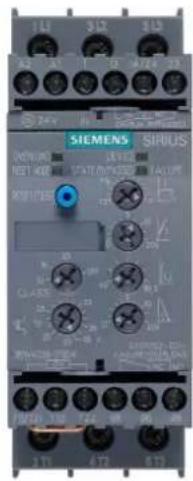
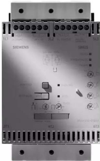
12.4.1 Commissioning procedure
- Check the voltages and wiring.
- Set the start and stop parameters (for recommended parameters, refer to the quick commissioning table).
- Set the motor overload function (if required)
- Define the RESET mode if a failure occurs.
- Start up the motor and if necessary optimize the parameters (refer to the quick commissioning table).
- Document the parameter settings if required.
12.4.2 Quick commissioning of the 3RW40 and optimization of the parameters
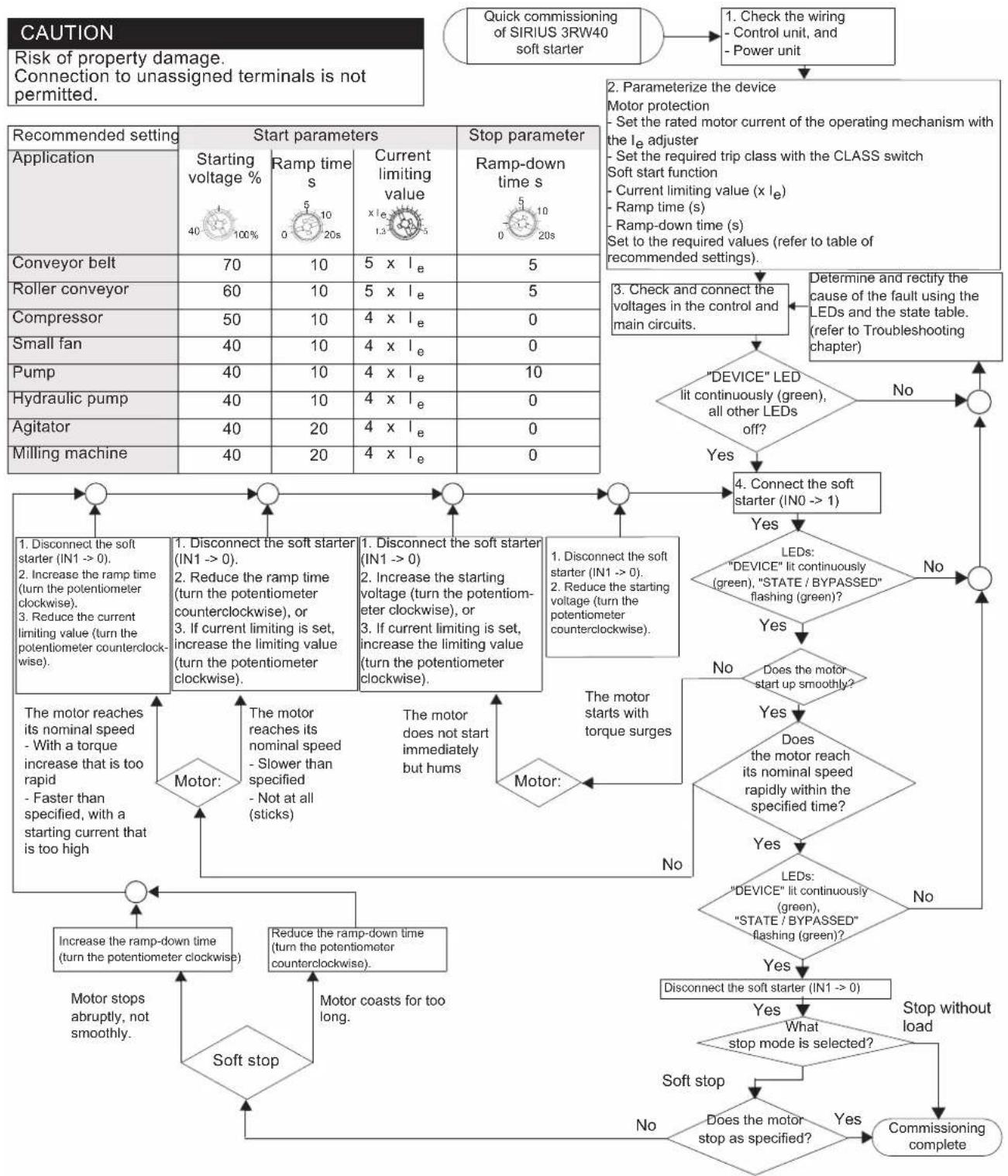
flowchart
graph TD
A["Quick commissioning of SIRIUS 3RW40 soft starter"] --> B["1. Check the wiring - Control unit, and - Power unit"]
B --> C["2. Parameterize the device Motor protection<br>- Set the rated motor current of the operating mechanism with the Ie adjuster<br>- Set the required trip class with the CLASS switch<br>Soft start function<br>- Current limiting value (x Ie)<br>- Ramp time (s)<br>- Ramp-down time (s)<br>Set to the required values (refer to table of recommended settings)."]
C --> D[""DEVICE" LED lit continuously (green), all other LEDs off?"]
D --> E{Yes}
E -->|No| F["4. Connect the soft starter (IN0 --> 1)"]
E -->|Yes| G["LEDs: "DEVICE" lit continuously (green), "STATE / BYPASSED" flashing (green)?"]
G --> H{Yes}
H -->|No| I["5. Disconnect the soft starter (IN1 --> 0)."]
H -->|Yes| J{Does the motor start up smoothly?}
J -->|No| K["7. Disconnect the soft starter (IN1 --> 0)."]
J -->|Yes| L{Does the motor reach its nominal speed rapidly within the specified time?}
L --> M{LEDs: "DEVICE" lit continuously (green), "STATE / BYPASSED" flashing (green)?}
M -->|No| N["8. Disconnect the soft starter (IN1 --> 0)."]
M -->|Yes| O["9. Disconnect the soft starter (IN1 --> 0)."]
O --> P{LEDs: "DEVICE" lit continuously (green), "STATE / BYPASSED" flashing (green)?}
P -->|No| Q["10. Disconnect the soft starter (IN1 --> 0)."]
P -->|Yes| R["11. Disconnect the soft starter (IN1 --> 0)."]
R --> S{LEDs: "DEVICE" lit continuously (green), "STATE / BYPASSED" flashing (green)?}
S -->|No| T["12. Disconnect the soft starter (IN1 --> 0)."]
S -->|Yes| U["13. Disconnect the soft starter (IN1 --> 0)."]
U --> V{LEDs: "DEVICE" lit continuously (green), "STATE / BYPASSED" flashing (green)?}
V -->|No| W["14. Disconnect the soft starter (IN1 --> 0)."]
V -->|Yes| X["15. Disconnect the soft starter (IN1 --> 0)."]
X --> Y{LEDs: "DEVICE" lit continuously (green), "STATE / BYPASSED" flashing (green)?}
Y -->|No| Z["16. Disconnect the soft starter (IN1 --> 0)."]
Y -->|Yes| AA["17. Disconnect the soft starter (IN1 --> 0)."]
AA --> AB{LEDs: "DEVICE" lit continuously (green), "STATE / BYPASSED" flashing (green)?}
AB -->|No| AC["18. Disconnect the soft starter (IN1 --> 0)."]
AB -->|Yes| AD["19. Disconnect the soft starter (IN1 --> 0)."]
AD --> AE{LEDs: "DEVICE" lit continuously (green), "STATE / BYPASSED" flashing (green)?}
AE -->|No| AF["20. Disconnect the soft starter (IN1 --> 0)."]
AE -->|Yes| AG["21. Disconnect the soft starter (IN1 --> 0)."]
12.4.3 Setting the soft start function
Voltage ramp
The SIRIUS 3RW40 achieves soft starting by means of a voltage ramp. The motor terminal voltage is increased from a parameterizable starting voltage to the mains voltage within a definable ramp time.

② M_Soft start Longer ramp time
③ M_Load (e.g. Fan)
12.4.4 Setting the starting voltage
U potentiometer
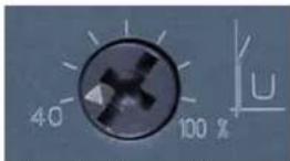
The starting voltage value is set with the U potentiometer. This value determines the starting torque of the motor. A lower starting voltage results in a lower starting torque (softer start) and a lower starting current.
The starting voltage selected must be sufficiently high to ensure that motor starts up smoothly as soon as the start command is received by the soft starter.
12.4.5 Setting the ramp time
t potentiometer
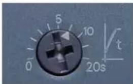
You define the length of the required ramp time with the t potentiometer. The ramp time determines the time taken to increase the motor voltage from the parameterized starting voltage to the mains voltage. This time merely influences the motor's acceleration torque, which drives the load during the ramp-up process. The actual motor starting times are load-dependent and can differ from the 3RW soft starter settings.
A longer ramp time results in a lower starting current and a reduced acceleration torque as the motor starts up. The startup is slower and smoother as a result. The ramp time must be long enough for the motor to reach its nominal speed. If the time selected is too short, in other words if the ramp time ends before the motor has started up successfully, a very high starting current that can even equal the direct starting current at the same speed occurs at this instant.
The SIRIUS 3RW40 soft starter additionally limits the current to the value set with the current limiting potentiometer. As soon as the current limiting value is reached, the voltage ramp or the ramp time is interrupted and the motor is started with the current limiting value until it has started up successfully. In this case, the motor ramp-up times may be longer than the maximum parameterizable 20 seconds ramp time or the ramp time that is actually set on the soft starter (for further information about the maximum ramp-up times and switching frequencies, refer to the Technical data chapter >3RW30 13, 14, 16, 17, 18-.BB.. power electronics [Page 124]) ff. and 3RW40 24, 26, 27, 28 power electronics [Page 149] ff.).
12.4.6 Current limiting in conjunction with a starting voltage ramp and ramp-up detection
Current limiting
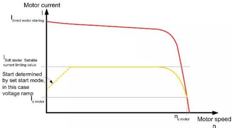
line
| Motor speed n | I_e motor | I_e motor starting | I_e motor setable current limiting value | | ------------- | --------- | ------------------ | ---------------------------------------- | | 0 | Low | High | Low | | n_e motor | Low | Low | Low | | >n_e motor | Decreasing | Decreasing | Decreasing |The SIRIUS 3RW40 soft starter measures the phase current (motor current) continuously with the help of integrated current transformers.
The motor current that flows during the startup process can be actively limited by means of the soft starter. The current limiting function takes priority over the voltage ramp function.
As soon as a parameterizable current limit is reached, in other words, the voltage ramp is interrupted and the motor is started with the current limiting value until it has started up successfully. The current limiting function is always active with SIRIUS 3RW40 soft starters. If the current limiting potentiometer is set to the clockwise stop (maximum), the starting current is limited to five times the set rated motor current.
12.4.7 Setting the motor current
I_e potentiometer
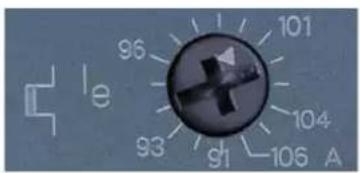
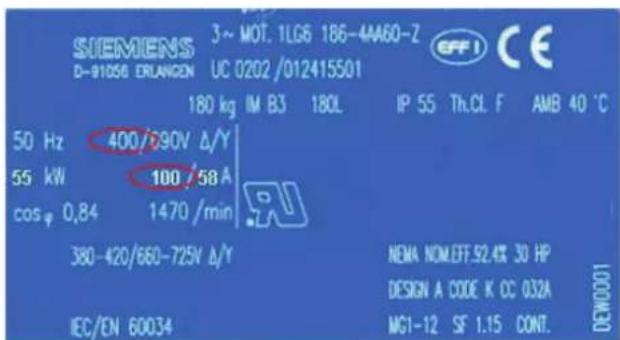
The rated operational current of the motor must be set with the I_e potentiometer according to the mains voltage and the motor connection (wye-delta). The electronic motor overload
12.4 Commissioning the 3RW40
protection also refers to this set value if it is active. For the permissible settings referred to the required motor overload trip class, refer to chapter Motor current settings [Page 107].
12.4.8 Setting the current limiting value
xl_e potentiometer
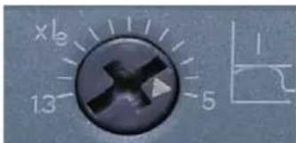
The current limiting value is set with the x_l_e potentiometer to the maximum required starting current as a factor of the set rated motor current ( I_e ).
Example
• I_e potentiometer set to 100 A
- xI_e potentiometer set to 5 => current limiting 500 A.
As soon as the selected current limiting value is reached, the motor voltage is reduced or controlled by the soft starter to prevent the current from exceeding the limit. Since the starting current is asymmetrical, the set current corresponds to the arithmetic mean value for the three phases.
If the current limiting value is set to the equivalent of 100 A, the starting currents might be approx. 80 A in L1, 120 A in L2, and 100 A in L3 (refer to chapter Starting current asymmetry [Page 21]).
The set current limiting value must be high enough to ensure that the torque generated in the motor is sufficient to accelerate the motor to nominal speed. Three to four times the value of the motor's rated operational current (I_e) can be assumed as typical here.
The current limiting function is always active because it is required by the intrinsic device protection. If the current limiting potentiometer is set to the clockwise stop (maximum), the starting current is limited to five times the set rated motor current.
12.4.9 Ramp-up detection
The SIRIUS soft starter has a motor ramp-up detection function that is always active regardless of the start mode. If it detects a motor startup, the motor voltage is immediately increased to 100% of the mains voltage. The thyristors of the soft starter are bridged by the bypass contacts integrated in the device and the successful startup is indicated by means of the BYPASS output and the STATE / BYPASSED LED.
12.5 Setting the soft stop function
In "soft stop" mode, the natural stop process of the load is decelerated. The function is used when the load must be prevented from stopping abruptly. This is typically the case in applications with a low mass inertia or a high counter-torque.
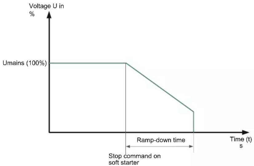
line
| Time (s) | Voltage U in (%) | | :--- | :--- | | 0 | Umains (100%) | | Ramp-down time (t) | 0 | | Stop command on soft starter | 0 |12.5.1 Setting the ramp-down time
t potentiometer
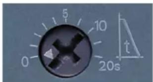
You can set a ramp-down time with the t potentiometer. This determines how long power should still be supplied to the motor after the ON command is removed. The torque generated in the motor is reduced by means of a voltage ramp function within this ramp-down time and the application stops smoothly.
If the potentiometer is set to 0, there is no voltage ramp during stopping (stop without load).
12.6 Setting the motor protection function
The motor overload protection function is implemented on the basis of the winding temperature. This indicates whether the motor is overloaded or functioning in the normal operating range.
The winding temperature can either be calculated with the help of the integrated, electronic motor overload function or measured with a connected motor thermistor.
12.6 Setting the motor protection function
12.6.1 Setting the electronic motor overload protection
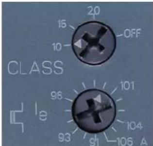
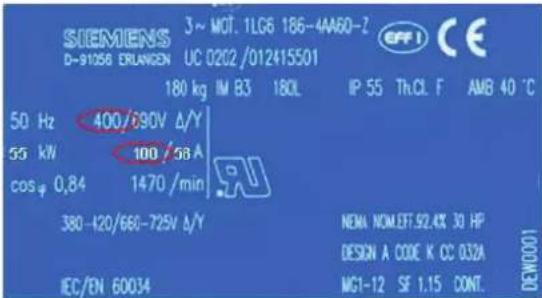
I_e potentiometer
The rated operational current of the motor must be set with the I_e potentiometer according to the mains voltage and the motor connection (wye-delta).
The current flow during motor operation is measured by measuring the current with transformers integrated in the soft starter. This value is also used for the current limiting function. The temperature rise in the winding is calculated based on the rated operational current set for the motor.
CLASS potentiometer
You can set the required trip class (10, 15, or 20) with the CLASS potentiometer. A trip is generated by the soft starter when the standardized characteristic is reached, depending on the trip class (CLASS setting).
The trip class specifies the maximum time within which a protective device must trip from a cold state at 7.2 x the rated operational current (motor protection to IEC 60947). The tripping characteristics represent this time as a function of the tripping current (refer to chapter Motor protection tripping characteristics for 3RW40 (with symmetry) [Page 161]).
You can set different CLASS characteristics according to the startup class. If the potentiometer is set to OFF, the "electronic motor overload protection" function is deactivated.
Note
The rated data of the soft starters refers to normal starting (CLASS 10). The starters may need to be calculated with a size allowance for heavy-duty starting (> CLASS 10). You can only set a rated motor current that is lower than the soft starter rated current (refer to chapter Motor current settings [Page 107]); if not, a fault will be indicated by the OVERLOAD LED (red flashing) and it will not be possible to start the SIRIUS 3RW soft starter.
12.6.2 Motor current settings
Motor current settings
| I_e [A] I | min [A] | I_max [A]CLASS 10 | I_max [A]CLASS 15 | I_max [A]CLASS 20 | |
| 3RW40 24-... 12 | 5 5 12.5 11 10 | ||||
| 3RW40 26-... 25 | 3 10.3 25.3 23 21 | ||||
| 3RW40 27-... 32 | 2 17.2 32.2 30 27 | ||||
| 3RW40 28-... 38 | 23 38 34 31 | ||||
| 3RW40 36-... 45 | 22.5 45 42 38 | ||||
| 3RW40 37-... 63 | 25.5 63 50 46 | ||||
| 3RW40 38-... 72 | 34.5 72 56 50 | ||||
| 3RW40 46-... 80 | 42.5 80 70 64 | ||||
| 3RW40 47-... 106 | 46 106 84 77 | ||||
| 3RW40 55-... 134 | 59 134 134 124 | ||||
| 3RW40 56-... 162 | 87 162 152 142 | ||||
| 3RW40 73-... 230 | 80 230 210 200 | ||||
| 3RW40 74-... 280 | 130 280 250 230 | ||||
| 3RW40 75-... 356 | 131 356 341 311 | ||||
| 3RW40 76-... 432 | 207 432 402 372 |
12.6.3 Motor protection acc. to ATEX
Refer to the information in chapter Motor protection / intrinsic device protection (3RW40 only) [Page 32].
12.7 Thermistor motor protection
12.7 Thermistor motor protection
(Optional for 3RW40 2. to 3RW40 4. with 24 V AC/DC rated control voltage)
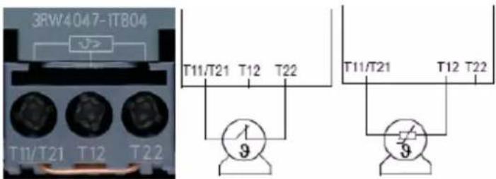
Klixon thermistor Type A PTC thermistor
Thermistor motor protection
After removing the copper jumper between T11/21 and T22, you can connect and evaluate either a Klixon thermistor integrated in the motor winding (at terminal T11/T21-T22) or a type A PTC (at terminal T11/T21-T12).
12.8 Motor protection trip test
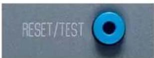
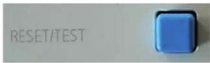
TEST / RESET button
You initiate a motor overload trip by pressing the RESET / TEST button for longer than five seconds. The SIRIUS 3RW40 soft starter is tripped by the fault signal at the OVERLOAD LED, the FAILURE / OVERLOAD contact 95-98 closes, and the motor that is connected and running is switched off.
12.9 Functions of the outputs
12.9.1 Functions of the BYPASSED and ON / RUN outputs
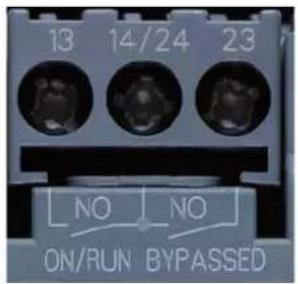
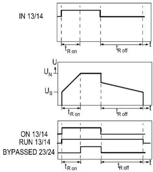
line
| Time | Signal | Duration | |------|--------|----------| | IN 13/14 | U_N | On | | IN 13/14 | U_S | Off | | ON 13/14 | U_N | On | | ON 13/14 | U_S | Off | | RUN 13/14 | U_N | On | | RUN 13/14 | U_S | Off | | BYPASSED 23/24 | U_N | On | | BYPASSED 23/24 | U_S | Off |BYPASSED output contact
The BYPASSED output at terminal 23 / 24 closes as soon as the SIRIUS 3RW40 soft starter detects that the motor has started up (refer to chapter Ramp-up detection [Page 104]). The integral bypass contacts simultaneously close and the thyristors are bridged. The integral bypass contacts and output 23 / 24 open again as soon as the start input IN is removed.
ON / RUN output contact
ON function set: The potential-free output contact at terminal 13/14 (ON) closes if a signal is present at terminal 1 (IN); it remains closed until the start command is removed (factory default). The ON function can be used, for instance, as a latching contact if you selected pushbutton control (refer to chapter Control by pushbutton [Page 168]).
Reparameterizing the output of the ON function (factory default) to RUN
You can reparameterize the output function from ON to RUN by simultaneously pressing two buttons (refer to chapter Parameterizing the 3RW40 outputs [Page 110]).
RUN function set: The potential-free output contact at terminal 13/14 closes if a signal is present at terminal 1 (IN); it remains closed until the start command is removed and after that until the set ramp-down time has elapsed.
If the RUN function is set, you can control a line contactor during the startup process, operation, or the set soft stop (refer to chapter Control with an optional main / line contactor [Page 1/7])
12.9 Functions of the outputs
For recommended circuits, refer to chapter Typical circuit diagrams [Page 167].
12.9.2 Parameterizing the 3RW40 outputs
Programming the ON / RUN output 13/14 on the SIRIUS 3RW40 soft starter
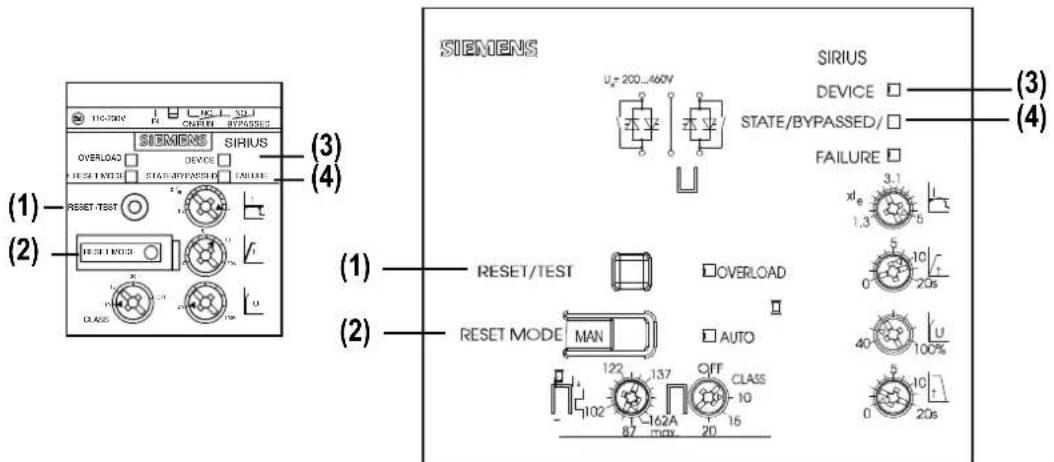
Figure 12-2 Overview of buttons / LEDs on the 3RW40 2 to 3RW40 4 and 3RW40 5 to 3RW40 7
| A | B | C | D | E | |
| RESET / TEST (1) | + >2 s => 1 s | s1 >s1 >Press to storeHold pressed down | |||
| RESET MODE (2) | |||||
| = | = | = | = = = | ||
| DEVICE (3) | gn=gn=rd=rd=gn | ||||
| STATE BYPASSED (4) | ● OFF=OFF | ON/ RUN | RUN/ ON | ● OFF | |
| FAILURE | ● OFF=OFF | OFF | O● | O● | |
| AUTO | ● / ☐ | ☐ / ● | ● / ☐ | ||
| OFF | ON | Flashing | Flickering |
Reparameterizing the ON / RUN output
A: Control voltage is present and the soft starter is in the normal, fault-free position: The DEVICE LED is continuously lit (green) while the STATE / BYPASSED and FAILURE LEDs are off. The AUTO LED indicates the color of the set RESET mode.
B: Start programming: (On the 3RW40 2 device, remove the RESET MODE cover as shown in chapter Setting the RESET MODE [Page 113].) Press the RESET MODE button (2) for longer than 2 s until the DEVICE LED (3) flickers (green). Hold the RESET MODE button (2) pressed down. C: Simultaneously press the RESET / TEST button (1) for longer than 1 s until the DEVICE LED (3) lights up (red). The active mode set at the ON / RUN output is indicated by the STATE / BYPASSED / FAILURE LED (4): STATE / BYPASSED / FAILURE LED (4) flashes (green): ON mode (factory setting). STATE / BYPASSED / FAILURE LED (4) flickers (green): RUN mode.
D: Change the mode: Press the RESET MODE button (2) briefly. By pressing this button, you change the mode at the output, and the new mode is indicated by the STATE / BYPASSED / FAILURE LED (4): STATE / BYPASSED / FAILURE LED (4) flickers (green): RUN mode is set. STATE / BYPASSED / FAILURE LED (4) flashes (green): ON mode is set.
E: Exit programming and save the settings: Press the RESET / TEST MODE button (1) for longer than 1 s until the DEVICE LED (3) lights up (green). The LEDs indicate the following states again if the output was successfully parameterized:
12.9 Functions of the outputs
DEVICE LED: Continuously lit (green).
STATE / BYPASSED and FAILURE LEDs: Off.
The AUTO LED indicates the color of the set RESET mode.
12.9.3 Function of the FAILURE / OVERLOAD output
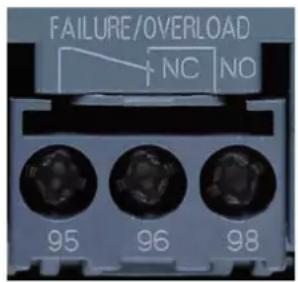
FAILURE / OVERLOAD output contact
If there is no rated control voltage or if a failure occurs, the potential-free FAILURE / OVERLOAD output is switched.
Note
For information about whether or not faults can be acknowledged, as well as the recovery time and the corresponding LED and output contact states, refer to chapter Diagnostics and fault signals [Page 44].
12.10 RESET MODE and functions of the RESET / TEST button
12.10.1 SIRIUS 3RW40 2. to 3RW40 4. soft starters
12.10.1.1 Setting the RESET MODE
Position of the RESET button behind the label on the 3RW40 2.
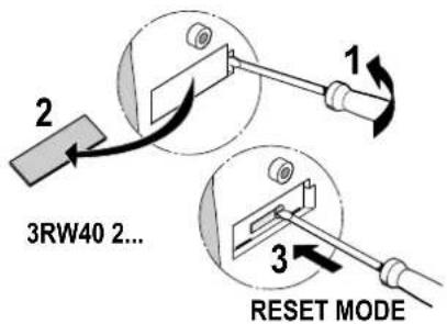
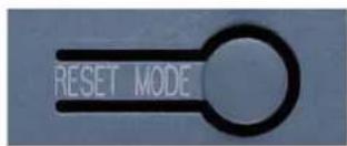
AUTO RESET Yellow
Manual RESET Off
Remote RESET Green
RESET MODE button
By pressing the RESET MODE button, you define the reset procedure in case of a fault. This is indicated by the RESET MODE LED.
12.10.1.2 Manual RESET
RESET / TEST button (RESET MODE LED off)
You can reset a fault by pressing the RESET / TEST button.
12.10 RESET MODE and functions of the RESET / TEST button
12.10.1.3 Remote RESET
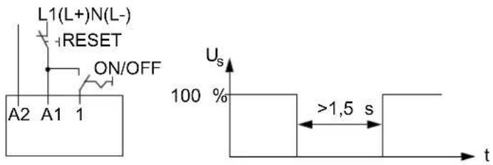
Remote RESET (RESET MODE LED = green)
You can reset a fault signal by disconnecting the control supply voltage for >1.5 s.
12.10.1.4 AUTO RESET
AUTO RESET (RESET MODE LED = yellow)
If you set the RESET mode to AUTO, a fault is automatically reset.
Note
For information about whether or not faults can be acknowledged, as well as the recovery time and the corresponding LED and output contact states, refer to chapter Diagnostics and fault signals [Page 44].

WARNING
Automatic restart
Can result in death, serious injury, or property damage.
The automatic RESET mode (AUTO RESET) must not be used in applications where there is a risk of serious injury to persons or substantial damage to property if the motor starts up again unexpectedly. The start command (e.g. issued by a contact or the PLC) must be reset prior to issuing a RESET command because the motor attempts to restart again automatically following this RESET command if a start command is still present. This particularly applies if the motor protection has tripped. For safety reasons, you are advised to integrate the group fault output on the 3RW40 (terminals 95 and 96), or the signaling contact of the motor or miniature circuit breaker on all devices, in the controller.
12.10.2 SIRIUS 3RW40 5. to 3RW40 7. soft starters
12.10.2.1 Setting the RESET MODE

AUTO RESET Yellow
Manual / (remote) RESET Off
RESET MODE button
By pressing the RESET MODE button, you define the reset procedure in case of a fault. This is indicated by the AUTO LED.
12.10.2.2 Manual RESET
RESET / TEST button (AUTO LED off)
You can reset a fault by pressing the RESET / TEST button.
12.10 RESET MODE and functions of the RESET / TEST button
12.10.2.3 Remote RESET
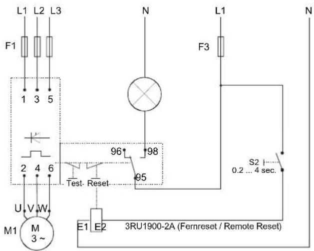
Remote RESET with module for RESET (AUTO LED = off)
You can perform a remote RESET (the RESET MODE set on the starter is MANUAL RESET) by controlling the optional module for RESET (3RU1900-2A).
12.10.2.4 AUTO RESET
AUTO RESET (AUTO LED = yellow)
If you set the RESET mode to AUTO, a fault is automatically reset.
Note
For information about whether or not faults can be acknowledged, as well as the recovery time and the corresponding LED and output contact states, refer to chapter Diagnostics and fault signals [Page 44].

WARNING
Automatic restart
Can result in death, serious injury, or property damage.
The automatic RESET mode (AUTO RESET) must not be used in applications where there is a risk of serious injury to persons or substantial damage to property if the motor starts up again unexpectedly. The start command (e.g. issued by a contact or the PLC) must be reset prior to issuing a RESET command because the motor attempts to restart again automatically following this RESET command if a start command is still present. This particularly applies if the motor protection has tripped. For safety reasons, you are advised to integrate the group fault output on the 3RW40 (terminals 95 and 96), or the signaling contact of the motor or miniature circuit breaker on all devices, in the controller.
12.11 3RW40: LEDs and troubleshooting
| LEDs on 3RW40 | Auxiliary contacts | ||||||||
| Soft starter | Motor protection | ||||||||
| 3RW40 | DEVICE(rd/gn/ylw) | STATE / BYPASSED / FAILURE (gn/rd) | OVERLOAD(rd) | RESET MODE / AUTO (ylw/gn) | 13 14(ON) | 13 14(RUN) | 24 23(BYPASSED) | 96 95 98 FAILURE / OVERLOAD | |
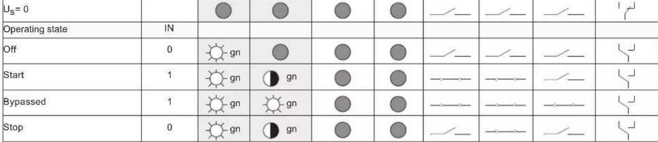 Warning Warning | |||||||||
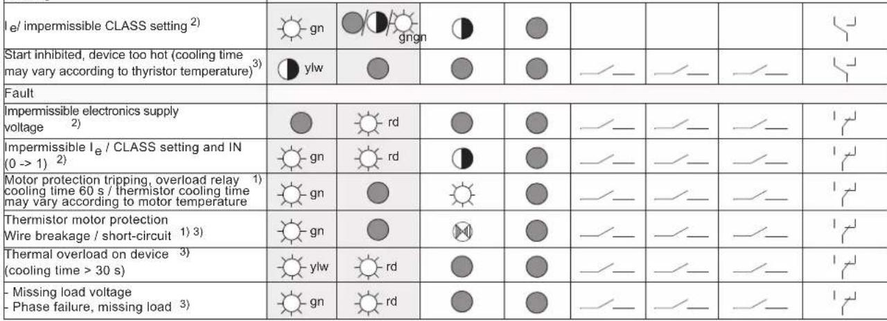 | |||||||||
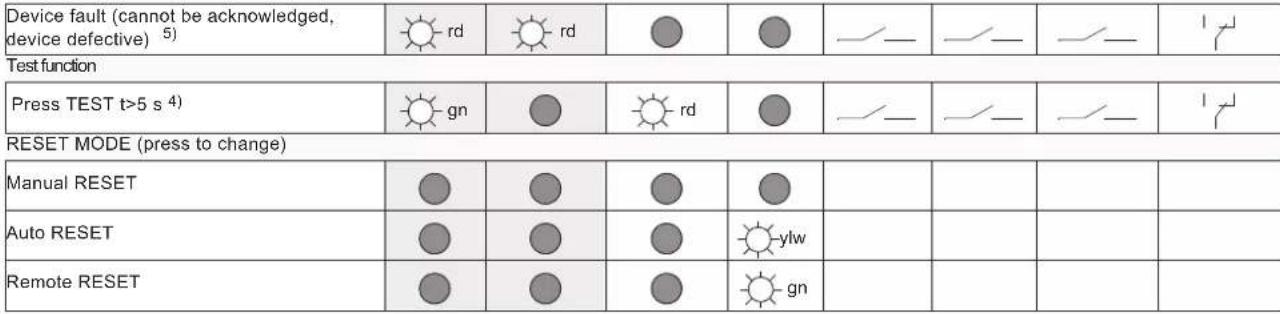 | |||||||||
 | |||||||||

WARNING
Automatic restart
Can result in death, serious injury, or property damage.
The automatic RESET mode (AUTO RESET) must not be used in applications where there is a risk of serious injury to persons or substantial damage to property if the motor starts up again unexpectedly. The start command (e.g. issued by a contact or the PLC) must be reset prior to issuing a RESET command because the motor attempts to restart again automatically following this RESET command if a start command is still present. This particularly applies if the motor protection has tripped. For safety reasons, you are advised to integrate the group fault output on the 3RW40 (terminals 95 and 96), or the signaling contact of the motor or miniature circuit breaker on all devices, in the controller.
Notes on troubleshooting
| Warning Cause Remedy | ||
| Impermissible I_e CLASS setting(control voltage present, no start command) | The rated operational current I_e set for the motor (control voltage present, no start command) exceeds the associated, maximum permissible setting current referred to the selected CLASS setting (chapterMotor current settings [Page 107]). | Check the rated operational current set for the motor, select a lower CLASS setting, or calculate the soft starter with a size allowance.As long as the 3RW40 is not controlled IN (0->1), this is only a status signal. However, it becomes a fault signal if the start command is applied. |
| Start inhibited, device too hot The acknowledgment and the motor start are inhibited for a defined time by the inherent device protection following an overload trip, to allow the 3RW40 to cool down.Possible causesToo many starts,Motor ramp-up time too long,Ambient temperature in switching device's environment too high,Minimum installation clearances not complied with. | The device cannot be started until the temperature of the thyristor or the heat sink has cooled down enough to guarantee sufficient reserve for a successful startup. The time until restarting is allowed can vary but is a minimum of 30 s.Rectify the causes and possibly retrofit the optional fan (3RW40 2. to 3RW40 4.). | |
| Fault Cause Remedy | ||
| Impermissible electronics supply voltage: | The control supply voltage does not correspond to the soft starter's rated voltage. | Check the control supply voltage; could be caused by a power failure, voltage dip, or incorrect control supply voltage. Use a stabilized power supply unit if due to mains fluctuations. |
| Impermissible le/CLASS setting and IN (0->1)(control voltage present, IN start command changes from 0 to 1) | The rated operational current I_e set for the motor (control voltage present, start command present) exceeds the associated, maximum permissible setting current referred to the selected CLASS setting (chapter Motor current settings [Page 107]).For the maximum permissible settings, refer to chapter "Technical data [Page 121)". | Check the rated operational current set for the motor, select a lower CLASS setting, or calculate the soft starter with a size allowance. |
| Motor protection tripping Overload relay / thermistor: | The thermal motor model has tripped. After an overload trip, restarting is inhibited until the recovery time has elapsed.- Overload relay tripping time: 60 s- Thermistor tripping time: When the temperature sensor (thermistor) in the motor has cooled down. | - Check whether the motor's rated operational current I_e is set correctly, or- Change the CLASS setting, or- Possibly reduce the switching frequency, or- Deactivate the motor protection (CLASS OFF), or- Check the motor and the application. |
| Thermistor protection: wire breakage / short-circuit (optional for 3RW40 2. to 3RW40 4. devices): | Temperature sensor at terminals T11/T12/T22 is short-circuited or defective, a cable is not connected, or no sensor is connected. | Check the temperature sensor and the wiring |
| Thermal overload on the device: Overload trip of the thermal model for the power unit of the 3RW40Possible causes• Too many starts,• Motor ramp-up time too long,• Ambient temperature in switching device's environment too high,• Minimum installation clearances not complied with. | Wait until the device has cooled down again, possibly increase the current limiting value set for starting, or reduce the switching frequency (too many consecutive starts). Possibly retrofit the optional fan (3RW40 2. to 3RW40 4.).Check the load and the motor, check whether the ambient temperature in the soft starter's environment is too high (derating above 40 °C, refer to chapter Technical data [Page 121]), comply with the minimum clearances. | |
12.11 3RW40: LEDs and troubleshooting
| Fault Cause Remedy | ||
| Missing load voltage, phase failure / missing load: | Cause 1: Phase L1 / L2 / L3 is missing or fails / collapses when the motor is operating.Tripped as a result of a dip in the permissible rated operational voltage > 15 % for > 100 ms during the startup process or > 200 ms in bypass mode. | Connect L1 / L2 / L3 or correct the voltage dip. |
| Cause 2: The motor that is connected is too small and the fault occurs as soon as it is switched to bypass mode. | Set the correct rated operational current for the connected motor or set it to the minimum value (if the motor current is less than 10 % of the set I_e , the motor cannot be operated with this starter). | |
| Cause 3: Motor phase T1 / T2 / T3 is not connected. | Connect the motor properly (e.g. jumpers in the motor terminal box, repair switch closed etc.) | |
| Device fault Soft starter defective. | Contact your SIEMENS partner or | Technical Assistance. |
Technical data
13.1 3RW30
13.1.1 Overview
SIRIUS 3RW30 soft starters reduce the motor voltage through variable phase angle control and increase it from a selectable starting voltage up to the mains voltage within the ramp time. They limit the starting current and torque, so that the shocks that occur during direct starts or wye-delta starting are avoided. Mechanical loads and mains voltage dips can be effectively prevented in this way.
Soft starting reduces the stress on the connected equipment, resulting in lower wear and therefore longer periods of trouble-free production. The selectable starting voltage means the soft starters can be individually adjusted to the requirements of the application in question and – unlike wye-delta starters – are not restricted to two-stage starting with fixed voltage ratios.
SIRIUS 3RW30 soft starters are characterized above all by their small space requirements. Integral bypass contacts mean that no power loss has to be taken into account at the power semiconductors (thyristors) after the motor has started up. This cuts down on heat losses, enabling a more compact design and making external bypass circuits superfluous.
Soft starters rated up to 55 kW (at 400 V) can be supplied for standard applications in three-phase systems. Extremely small sizes, low power losses and simple startup are just three of the many advantages of this soft starter.
13.1.2 Selection and ordering data for standard applications and normal starting
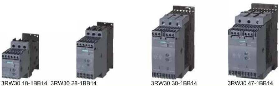
| Ambient temperature 40°C | Ambient temperature 50°C | Size | Normal starting | ||||||
| Rated operational current I_e^1) | Rated power of three-phase induction motors for rated operational voltage U_e | Rated operational current V_e^1) | Rated power of three-phase induction motors for rated operational voltage U_e | Order No. | |||||
| 500 V400V230 V | 575 V460 V230 V200 V | ||||||||
| A | kW | kW | kW | A | hp | hp | hp | hp | |
Rated operational voltage U_e 200 to 480 V ^2)
| • With screw or spring-loaded terminals | |||||||||
| 3.6 | 0.75 | 1.5 | - | 3 | 0.5 | 0.5 | 1.5 | - | S00 |
| 6.5 | 1.5 | 3 | - | 4.8 | 1 | 1 | 3 | - | S00 |
| 9 | 2.2 | 4 | - | 7.8 | 2 | 2 | 5 | - | S00 |
| 12.5 | 3 | 5.5 | - | 11 | 3 | 3 | 7.5 | - | S00 |
| 17.6 | 4 | 7.5 | - | 17 | 3 | 3 | 10 | - | S00 |
| • With screw terminals | |||||||||
| 25 | 5.5 | 11 | - | 23 | 5 | 5 | 15 | - | S0 |
| 32 | 7.5 | 15 | - | 29 | 7.5 | 7.5 | 20 | - | S0 |
| 38 | 11 | 18.5 | - | 34 | 10 | 10 | 25 | - | S0 |
| • With screw or spring-loaded terminals | |||||||||
| 45 | 11 | 22 | - | 42 | 10 | 15 | 30 | - | S2 |
| 58 | 18.5 | 30 | - | 58 | 15 | 20 | 40 | - | S2 |
| 72 | 22 | 37 | - | 62 | 20 | 20 | 40 | - | S2 |
| • With screw or spring-loaded terminals | |||||||||
| 80 | 22 | 45 | - | 73 | 20 | 25 | 50 | - | S3 |
| 106 | 30 | 55 | - | 98 | 30 | 30 | 75 | - | S3 |
Order number supplement for connection types
- With screw terminals
- With spring-loaded terminals ^3
Order number supplement for rated control supply voltage U_s
• 24 V AC/DC
• 110 to 230 V AC/DC
1) Standalone assembly without additional fan.
2)Soft starter with screw terminals.
3) Main circuit connection: screw terminals.
Note
The rated motor current is extremely important when selecting a soft starter.
Refer to the information about selecting soft starters in chapter Configuration [Page 73].
Conditions for normal starting:
Max. ramp time 3 s, starting current 300 %, 20 starts / hour, ON time 30 %, standalone assembly, max. installation altitude 1000 m / 3280 ft, ambient temperature kW 40 °C / 104 °F. A larger model may need to be selected if other conditions and constraints apply or for a higher starting frequency. We recommend using the "Win-Soft Starter" selection and simulation software. For information about the rated currents for ambient temperatures > 40 °C, refer to chapter 3RW30..-BB.. power electronics [Page 124].
13.1.3 3RW30..-BB.. control electronics
| Type | 3RW301., 3RW302. 3RW303., 3RW304. | ||||||
| Control electronics | |||||||
| Rated values | Terminal | ||||||
| Rated control supply voltage | A1 / A2 | V | 24 | 110...230 | 24 | 110...230 | |
| • Tolerance | % | ±20 | -15/+10 | ±20 | -15/+10 | ||
| Rated control supply current | |||||||
| • STANDBY | mA | <50 | 6 | <5020 | |||
| • During pickup | mA | <500 | |||||
| • ON | mA | <502015<100 | |||||
| Rated frequency | Hz | 50/60 | |||||
| • Tolerance | % | ±10 | |||||
| Control input | |||||||
| IN | ON / OFF | ||||||
| Power consumption with version | |||||||
| • 24 V DC | mA | approx. 12 | |||||
| • 110/230 V AC | mA | AC: 3/6; DC: 1.5/3 | |||||
| Relay outputs | |||||||
| Output 1 | ON | 13/14 | Operating indication (NO) | ||||
| Rated operational current | A | 3AC-15/AC-14 at 230 V,1DC-13 at 24 V | |||||
| Protection against overvoltages | Protection by means of varistor through contact4 A gL/gG operational class;6 A quick (fuse is not included in scope of supply) | ||||||
| Short-circuit protection | |||||||
| Operating indications | LED | STATE/BYPASSED/FAILURE | DEVICEDEVICE | STATE/BYPASSED/FAILURE | |||
| Off Start Bypass | OffGreenOffGreenGreen Green Green Green Green Green Green Green Green Green Green Green Green Green Green Green Green Green Green Green Green Green Green Green Green Green Green Green Green Green Green Green Green Green Green Green Green Green Green Green Green Green Green Green Green Green Green Green Green Green Green Green Green Green Green Green Green Green Green Green Green Green Green Green Green Green Green Green Green Green Green Green Green Green Green Green Green Green Green Green Green Green Green Green Green Green Green Green Green Green Green Green Green Green Green Green Green Green Green Green Green Greenland Green Green Green Green Green Green Green Green Green Green Green Green Green Green Green Green Green Green Green Green Green Green Green Green Green Green Green Green Green Green Green Green Green Green Green Green Green Green Green Green Green Green Green Green Green Green Green Green Green Green Green Green Green Green Green Green Green Green Green Green Green Green Green Green Green Green Green Green Green Green Green Green Green Green Green Green Green Green Green Green Green Green Green Green Green Green Green Green Green Green Green Green Green Green Green Green Green Green GreenGreen Green Green Green Green Green Green Green Green Green Green Green Green Green Green Green Green Green Green Green Green Green Green Green Green Green Green Green Green Green Green Green Green Green Green Green Green Green Green Green Green Green Green Green Green Green Green Green Green Green Green Green Green Green Green Green Green Green Green Green Green Green Green Green Green Green Green Green Green Green Green Green Green Green Green Green Green Green Green Green Green Green Green Green Green Green Green Green Green Green Green Green Green Green Green Green Green Green GreenGreenGreenGreenGreenGreenGreenGreenGreenGreenGreenGreenGreenGreenGreenGreenGreenGreenGreenGreenGreenGreenGreenGreenGreenGreenGreenGreenGreenGreenGreenGreenGreenGreenGreenGreenGreenGreenGreenGreenGreenGreenGreenGreenGreenGreenGreenGreenGreenGreenGreenGreenGreenGreenGreenGreenGreenGreenGreenGreenGreenGreenGreenGreenGreenGreenGreenGreenGreenGreenGreenGreenGreenGreenGreenGreenGreenGreenGreenGreenGreenGreenGreenGreenGreenGreenGreenGreenGreenGreenGreenGreenGreenGreenGreenGreenGreenGreenGreenGreenGreen Green Green Green Green Green Green Green Green Green Green Green Green Green Green Green Green Green Green Green Green Green Green Green Green Green Green Green Green Green Green Green Green Green Green Green Green Green Green Green Green Green Green Green Green Green Green Green Green Green Green Green Green Green Green Green Green Green Green Green Green Green Green Green Green Green Green Green Green Green Green Green Green Green Green Green Green Green Green Green Green Green Green Green Green Green Green Green Green Green Green Green Green Green Green Green Green GreenGreen GreenGreen Green Green Green Green Green Green Green Green Green Green Green Green Green Green Green Green Green Green Green Green Green Green Green Green Green Green Green Green Green Green Green Green Green Green Green Green Green Green Green Green Green Green Green Green Green Green Green Green Green Green Green Green Green Green Green Green Green Green Green Green Green Green Green Green Green Green Green Green Green Green Green Green Green Green Green Green Green Green Green Green Green Green Green Green Green Green Green Green Green Green Green Green Green Green Green Green GreenGreenGreen Green Green Green Green Green Green Green Green Green Green Green Green Green Green Green Green Green Green Green Green Green Green Green Green Green Green Green Green Green Green Green Green Green Green Green Green Green Green Green Green Green Green Green Green Green Green Green Green Green Green Green Green Green Green Green Green Green Green Green Green Green Green Green Green Green Green Green Green Green Green Green Green Green Green Green Green Green Green Green Green Green Green Green Green Green Green Green Green Green Green Green Green Green Green Green Green Green GreenlandGreenGreenGreenGreenGreenGreenGreenGreenGreenGreenGreenGreenGreenGreenGreenGreenGreenGreenGreenGreenGreenGreenGreenGreenGreenGreenGreenGreenGreenGreenGreenGreenGreenGreenGreenGreenGreenGreenGreenGreenGreenGreenGreenGreenGreenGreenGreenGreenGreenGreenGreenGreenGreenGreenGreenGreenGreenGreenGreenGreenGreenGreenGreenGreenGreenGreenGreenGreenGreenGreenGreenGreenGreenGreenGreenGreenGreenGreenGreenGreenGreenGreenGreenGreenGreenGreenGreenGreenGreenGreenGreenGreenGreenGreenGreenGreenGreenGreenGreen GreenlandGreenGreenGreenGreenGreenGreenGreenGreenGreenGreenGreenGreenGreenGreenGreenGreenGreenGreenGreenGreenGreenGreenGreenGreenGreenGreenGreenGreenGreenGreenGreenGreenGreenGreenGreenGreenGreenGreenGreenGreenGreenGreenGreenGreenGreenGreenGreenGreenGreenGreenGreenGreenGreenGreenGreenGreenGreenGreenGreenGreenGreenGreenGreenGreenGreenGreenGreenGreenGreenGreenGreenGreenGreenGreenGreenGreenGreenGreenGreenGreenGreenGreenGreenGreenGreenGreenGreenGreenGreenGreenGreenGreenGreenGreenGreenGreenGreenGreen Greenland Greenland Greenland Greenland Greenland Greenland Greenland Greenland Greenland Greenland Greenland Greenland Greenland Greenland Greenland Greenland Greenland Greenland Greenland Greenland Greenland Greenland Greenland Greenland Greenland Greenland Greenland Greenland Greenland Greenland Greenland Greenland Greenland Greenland Greenland Greenland Greenland Greenland Greenland Greenland Greenland Greenland Greenland Greenland Greenland Greenland Greenland Greenland Greenland Greenland Greenland Greenland Greenland Greenland Greenland Greenland Greenland Greenland Greenland Greenland Greenland Greenland Greenland Greenland Greenland Greenland Greenland Greenland Greenland Greenland Greenland Greenland Greenland Greenland Greenland Greenland Greenland Greenland Greenland Greenland Greenland Greenland Greenland Greenland Greenland Greenland Greenland Greenland Greenland Greenland Greenland Greenland Greenland Greenland Greenland Greenland Greenland Greenland Greenland Greenland Green Greenland Greenland Greenland Greenland Greenland Greenland Greenland Greenland Greenland Greenland Greenland Greenland Greenland Greenland Greenland Greenland Greenland Greenland Greenland Greenland Greenland Greenland Greenland Greenland Greenland Greenland Greenland Greenland Greenland Greenland Greenland Greenland Greenland Greenland Greenland Greenland Greenland Greenland Greenland Greenland Greenland Greenland Greenland Greenland Greenland Greenland Greenland Greenland Greenland Greenland Greenland Greenland Greenland Greenland Greenland Greenland Greenland Greenland Greenland Greenland Greenland Greenland Greenland Greenland Greenland Greenland Greenland Greenland Greenland Greenland Greenland Greenland Greenland Greenland Greenland Greenland Greenland Greenland Greenland Greenland Greenland Greenland Greenland Greenland Greenland Greenland Greenland Greenland Greenland Greenland Greenland Greenland Greenland Greenland Greenland Greenland Greenland Greenland GreenlandGreen Greenland Greenland Greenland Greenland Greenland Greenland Greenland Greenland Greenland Greenland Greenland Greenland Greenland Greenland Greenland Greenland Greenland Greenland Greenland Greenland Greenland Greenland Greenland Greenland Greenland Greenland Greenland Greenland Greenland Greenland Greenland Greenland Greenland Greenland Greenland Greenland Greenland Greenland Greenland Greenland Greenland Greenland Greenland Greenland Greenland Greenland Greenland Greenland Greenland Greenland Greenland Greenland Greenland Greenland Greenland Greenland Greenland Greenland Greenland Greenland Greenland Greenland Greenland Greenland Greenland Greenland Greenland Greenland Greenland Greenland Greenland Greenland Greenland Greenland Greenland Greenland Greenland Greenland Greenland Greenland Greenland Greenland Greenland Greenland Greenland Greenland Greenland Greenland Greenland Greenland Greenland Greenland Greenland Greenland Greenland Greenland Greenland Greenland Green Green Greenland Greenland Greenland Greenland Greenland Greenland Greenland Greenland Greenland Greenland Greenland Greenland Greenland Greenland Greenland Greenland Greenland Greenland Greenland Greenland Greenland Greenland Greenland Greenland Greenland Greenland Greenland Greenland Greenland Greenland Greenland Greenland Greenland Greenland Greenland Greenland Greenland Greenland Greenland Greenland Greenland Greenland Greenland Greenland Greenland Greenland Greenland Greenland Greenland Greenland Greenland Greenland Greenland Greenland Greenland Greenland Greenland Greenland Greenland Greenland Greenland Greenland Greenland Greenland Greenland Greenland Greenland Greenland Greenland Greenland Greenland Greenland Greenland Greenland Greenland Greenland Greenland Greenland Greenland Greenland Greenland Greenland Greenland Greenland Greenland Greenland Greenland Greenland Greenland Greenland Greenland Greenland Greenland Greenland Greenland Greenland Greenland Greenland Green Rain Red Red Red Red Red Red Red Red Red Red Red Red Red Red Red Red Red Red Red Red Red Red Red Red Red Red Red Red Red Red Red Red Red Red Red Red Red Red Red Red Red Red Red Red Red Red Red Red Red Red Red Red Red Red Red Red Red Red Red Red Red Red Red Red Red Red Red Red Red Red Red Red Red Red Red Red Red Red Red Red Red Red Red Red Red Red Red Red Red Red Red Red Red Red Red Red Red Red Red RedRed Red Red Red Red Red Red Red Red Red Red Red Red Red Red Red Red Red Red Red Red Red Red Red Red Red Red Red Red Red Red Red Red Red Red Red Red Red Red Red Red Red Red Red Red Red Red Red Red Red Red Red Red Red Red Red Red Red Red Red Red Red Red Red Red Red Red Red Red Red Red Red Red Red Red Red Red Red Red Red Red Red Red Red Red Red Red Red Red Red Red Red Red Red Red Red Red Red Red Red red red red red red red red red red red red red red red red red red red red red red red red red red red red red red red red red red red red red red red red red red red red red red red red red red red red red red red red red red red red red red red red red red red red red red red red red red red red red red red red red red red red red red red red red red red red red red red red red red red red redred red red red red red red red red red red red red red red red red red red red red red red red red red red red red red red red red red red red red red red red red red red red red red red red red red red red red red red red red red red red red red red red red red red red red red red red red red red red red red red red red red red red red red red red red red red red red red red red red red red red-red red red red red red red red red red red red red red red red red red red red red red red red red red red red red red red red red red red red red red red red red red red red red red red red red red red red red red red red red red red red red red red red red red red red red red red red red red red red red red red red red red red red red red red red red red red red red red red red red red red red Red Red Red Red Red Red Red Red Red Red Red Red Red Red Red Red Red Red Red Red Red Red Red Red Red Red Red Red Red Red Red Red Red Red Red Red Red Red Red Red Red Red Red Red Red Red Red Red Red Red Red Red Red Red Red Red Red Red Red Red Red Red Red Red Red Red Red Red Red Red Red Red Red Red Red Red Red Red Red Red Red Red Red Red Red Red Red Red Red Red Red Red Red Red Red Red Red Red Red红红红红红红红红红红红红红红红红红红红红红红红红红红红红红红红红红红红红红红红红红红红红红红红红红红红红红红红红红红红红红红红红红红红红红红红红红红红红红红红红红红红红红红红红红红红红红红红红红红红红红色红红红红红红红红红红红红红红红红红红红红红红红红红红红红红红红红红红红红红红红红红红红红红红红红红红红红红红红红红红红红红红红红红红红红红红红红红红红红红红红红红红红红红红红红红红红红红红红红红红红紅红红红红红红红红红红红红红红红红红红红红红红红红红红红红红红红红红红红红红红红红红红红红红红红红红红红红红红红红红红红红红红红红红红红红红红红红红红红红红红红红红红红红红红红红红红红红红红红红红红红黄红红红红红红红红红红红红红红红红红红红红红红红红红红红红红红红红红红红红红红红红红红红红红红红红红红红红红红红红红红红红红红红红红红红红红红红红红红红红红红红红红红红红红红红红红红红红红红红红红红红灯灯灯灯灯灯灯灯灯灯灯灯灯灯灯灯灯灯灯灯灯灯灯灯灯灯灯灯灯灯灯灯灯灯灯灯灯灯灯灯灯灯灯灯灯灯灯灯灯灯灯灯灯灯灯灯灯灯灯灯灯灯灯灯灯灯灯灯灯灯灯灯灯灯灯灯灯灯灯灯灯灯灯灯灯灯灯灯灯灯灯灯灯灯灯灯灯灯灯灯火灯灯灯灯灯灯灯灯灯灯灯灯灯灯灯灯灯灯灯灯灯灯灯灯灯灯灯灯灯灯灯灯灯灯灯灯灯灯灯灯灯灯灯灯灯灯灯灯灯灯灯灯灯灯灯灯灯灯灯灯灯灯灯灯灯灯灯灯灯灯灯灯灯灯灯灯灯灯灯灯灯灯灯灯灯灯灯灯灯灯灯灯灯灯灯灯灯灯灯光灯灯灯灯灯灯灯灯灯灯灯灯灯灯灯灯灯灯灯灯灯灯灯灯灯灯灯灯灯灯灯灯灯灯灯灯灯灯灯灯灯灯灯灯灯灯灯灯灯灯灯灯灯灯灯灯灯灯灯灯灯灯灯灯灯灯灯灯灯灯灯灯灯灯灯灯灯灯灯灯灯灯灯灯灯灯灯灯灯灯灯灯灯灯灯灯灯灯灯的灯灯灯灯灯灯灯灯灯灯灯灯灯灯灯灯灯灯灯灯灯灯灯灯灯灯灯灯灯灯灯灯灯灯灯灯灯灯灯灯灯灯灯灯灯灯灯灯灯灯灯灯灯灯灯灯灯灯灯灯灯灯灯灯灯灯灯灯灯灯灯灯灯灯灯灯灯灯灯灯灯灯灯灯灯灯灯灯灯灯灯灯灯灯灯灯灯灯灯门灯灯灯灯灯灯灯灯灯灯灯灯灯灯灯灯灯灯灯灯灯灯灯灯灯灯灯灯灯灯灯灯灯灯灯灯灯灯灯灯灯灯灯灯灯灯灯灯灯灯灯灯灯灯灯灯灯灯灯灯灯灯灯灯灯灯灯灯灯灯灯灯灯灯灯灯灯灯灯灯灯灯灯灯灯灯灯灯灯灯灯灯灯灯灯灯灯灯灯燈燈燈燈燈燈燈燈燈燈燈燈燈燈燈燈燈燈燈燈燈燈燈燈燈燈燈燈燈燈燈燈燈燈燈燈燈燈燈燈燈燈燈燈燈燈燈燈燈燈燈燈燈燈燈燈燈燈燈燈燈燈燈燈燈燈燈燈燈燈燈燈燈燈燈燈燈燈燈燈燈燈燈燈燈燈燈燈燈燈燈燈燈燈燈燈燈燈燈燈電燈燈燈燈燈燈燈燈燈燈燈燈燈燈燈燈燈燈燈燈燈燈燈燈燈燈燈燈燈燈燈燈燈燈燈燈燈燈燈燈燈燈燈燈燈燈燈燈燈燈燈燈燈燈燈燈燈燈燈燈燈燈燈燈燈燈燈燈燈燈燈燈燈燈燈燈燈燈燈燈燈燈燈燈燈燈燈燈燈燈燈燈燈燈燈燈燈燈燈烟燈燈燈燈燈燈燈燈燈燈燈燈燈燈燈燈燈燈燈燈燈燈燈燈燈燈燈燈燈燈燈燈燈燈燈燈燈燈燈燈燈燈燈燈燈燈燈燈燈燈燈燈燈燈燈燈燈燈燈燈燈燈燈燈燈燈燈燈燈燈燈燈燈燈燈燈燈燈燈燈燈燈燈燈燈燈燈燈燈燈燈燈燈燈燈燈燈燈燈熄火器或过载过载过载过载过载过载过载过载过载过载过载过载过载过载过载过载过载过载过载过载过载过载过载过载过载过载过载过载过载过载过载过载过载过载过载过载过载过载过载过载过载过载过载过载过载过载过载过载过载过载过车时钟钟钟钟钟钟钟钟钟钟钟钟钟钟钟钟钟钟钟钟钟钟钟钟钟钟钟钟钟钟钟钟钟钟钟钟钟钟钟钟钟钟钟钟钟钟钟钟钟钟钟钟钟钟钟钟钟钟钟钟钟钟钟钟钟钟钟钟钟钟钟钟钟钟钟钟钟钟钟钟钟钟钟钟钟钟钟钟钟钟钟钟钟钟钟钟钟钟钟钟 Clock钟钟钟钟钟钟钟钟钟钟钟钟钟钟钟钟钟钟钟钟钟钟钟钟钟钟钟钟钟钟钟钟钟钟钟钟钟钟钟钟钟钟钟钟钟钟钟钟钟钟钟钟钟钟钟钟钟钟钟钟钟钟钟钟钟钟钟钟钟钟钟钟钟钟钟钟钟钟钟钟钟钟钟钟钟钟钟钟钟钟钟钟钟钟钟钟钟钟钟针钟钟钟钟钟钟钟钟钟钟钟钟钟钟钟钟钟钟钟钟钟钟钟钟钟钟钟钟钟钟钟钟钟钟钟钟钟钟钟钟钟钟钟钟钟钟钟钟钟钟钟钟钟钟钟钟钟钟钟钟钟钟钟钟钟钟钟钟钟钟钟钟钟钟钟钟钟钟钟钟钟钟钟钟钟钟钟钟钟钟钟钟钟钟钟钟钟钟钟长白石墨墨墨墨墨墨墨墨墨墨墨墨墨墨墨墨墨墨墨墨墨墨墨墨墨墨墨墨墨墨墨墨墨墨墨墨墨墨墨墨墨墨墨墨墨墨墨墨墨墨墨墨墨墨墨墨墨墨墨墨墨墨墨墨墨墨墨墨墨墨墨墨墨墨墨墨墨墨墨墨墨墨墨墨墨墨墨墨墨墨墨墨墨墨墨墨墨墨墨墨黑墨墨墨墨墨墨墨墨墨墨墨墨墨墨墨墨墨墨墨墨墨墨墨墨墨墨墨墨墨墨墨墨墨墨墨墨墨墨墨墨墨墨墨墨墨墨墨墨墨墨墨墨墨墨墨墨墨墨墨墨墨墨墨墨墨墨墨墨墨墨墨墨墨墨墨墨墨墨墨墨墨墨墨墨墨墨墨墨墨墨墨墨墨墨墨墨墨墨墨画墨墨墨墨墨墨墨墨墨墨墨墨墨墨墨墨墨墨墨墨墨墨墨墨墨墨墨墨墨墨墨墨墨墨墨墨墨墨墨墨墨墨墨墨墨墨墨墨墨墨墨墨墨墨墨墨墨墨墨墨墨墨墨墨墨墨墨墨墨墨墨墨墨墨墨墨墨墨墨墨墨墨墨墨墨墨墨墨墨墨墨墨墨墨墨墨墨墨墨玉墨墨墨墨墨墨墨墨墨墨墨墨墨墨墨墨墨墨墨墨墨墨墨墨墨墨墨墨墨墨墨墨墨墨墨墨墨墨墨墨墨墨墨墨墨墨墨墨墨墨墨墨墨墨墨墨墨墨墨墨墨墨墨墨墨墨墨墨墨墨墨墨墨墨墨墨墨墨墨墨墨墨墨墨墨墨墨墨墨墨墨墨墨墨墨墨墨墨墨碧墨墨墨墨墨墨墨墨墨墨墨墨墨墨墨墨墨墨墨墨墨墨墨墨墨墨墨墨墨墨墨墨墨墨墨墨墨墨墨墨墨墨墨墨墨墨墨墨墨墨墨墨墨墨墨墨墨墨墨墨墨墨墨墨墨墨墨墨墨墨墨墨墨墨墨墨墨墨墨墨墨墨墨墨墨墨墨墨墨墨墨墨墨墨墨墨墨墨墨木墨墨墨墨墨墨墨墨墨墨墨墨墨墨墨墨墨墨墨墨墨墨墨墨墨墨墨墨墨墨墨墨墨墨墨墨墨墨墨墨墨墨墨墨墨墨墨墨墨墨墨墨墨墨墨墨墨墨墨墨墨墨墨墨墨墨墨墨墨墨墨墨墨墨墨墨墨墨墨墨墨墨墨墨墨墨墨墨墨墨墨墨墨墨墨墨墨墨墨素墨墨墨墨墨墨墨墨墨墨墨墨墨墨墨墨墨墨墨墨墨墨墨墨墨墨墨墨墨墨墨墨墨墨墨墨墨墨墨墨墨墨墨墨墨墨墨墨墨墨墨墨墨墨墨墨墨墨墨墨墨墨墨墨墨墨墨墨墨墨墨墨墨墨墨墨墨墨墨墨墨墨墨墨墨墨墨墨墨墨墨墨墨墨墨墨墨墨墨铜墨墨墨墨墨墨墨墨墨墨墨墨墨墨墨墨墨墨墨墨墨墨墨墨墨墨墨墨墨墨墨墨墨墨墨墨墨墨墨墨墨墨墨墨墨墨墨墨墨墨墨墨墨墨墨墨墨墨墨墨墨墨墨墨墨墨墨墨墨墨墨墨墨墨墨墨墨墨墨墨墨墨墨墨墨墨墨墨墨墨墨墨墨墨墨墨墨墨墨漆墨墨墨漆墨漆墨漆墨漆墨漆墨漆墨漆墨漆墨漆墨漆墨漆墨漆墨漆墨漆墨漆墨漆墨漆墨漆墨漆墨漆墨漆墨漆墨漆墨漆墨漆墨漆墨漆墨漆墨漆墨漆墨漆墨漆墨漆墨漆墨漆墨漆墨漆墨漆墨漆墨漆墨漆墨漆墨漆墨漆墨漆墨漆墨漆墨漆墨漆墨漆墨塗層石器石器石器石器石器石器石器石器石器石器石器石器石器石器石器石器石器石器石器石器石器石器石器石器石器石器石器石器石器石器石器石器石器石器石器石器石器石器石器石器石器石器石器石器石器石器石器石器石器石器石电器石器石器石器石器石器石器石器石器石器石器石器石器石器石器石器石器石器石器石器石器石器石器石器石器石器石器石器石器石器石器石器石器石器石器石器石器石器石器石器石器石器石器石器石器石器石器石器石器石器石电石器石器石器石器石器石器石器石器石器石器石器石器石器石器石器石器石器石器石器石器石器石器石器石器石器石器石器石器石器石器石器石器石器石器石器石器石器石器石器石器石器石器石器石器石器石器石器石器石器石色石器石器石器石器石器石器石器石器石器石器石器石器石器石器石器石器石器石器石器石器石器石器石器石器石器石器石器石器石器石器石器石器石器石器石器石器石器石器石器石器石器石器石器石器石器石器石器石器石器石三石器石器石器石器石器石器石器石器石器石器石器石器石器石器石器石器石器石器石器石器石器石器石器石器石器石器石器石器石器石器石器石器石器石器石器石器石器石器石器石器石器石器石器石器石器石器石器石器石器石盘石器石器石器石器石器石器石器石器石器石器石器石器石器石器石器石器石器石器石器石器石器石器石器石器石器石器石器石器石器石器石器石器石器石器石器石器石器石器石器石器石器石器石器石器石器石器石器石器石器石塔石器石器石器石器石器石器石器石器石器石器石器石器石器石器石器石器石器石器石器石器石器石器石器石器石器石器石器石器石器石器石器石器石器石器石器石器石器石器石器石器石器石器石器石器石器石器石器石器石器石圈石器石器石器石器石器石器石器石器石器石器石器石器石器石器石器石器石器石器石器石器石器石器石器石器石器石器石器石器石器石器石器石器石器石器石器石器石器石器石器石器石器石器石器石器石器石器石器石器石器石圆石器石器石器石器石器石器石器石器石器石器石器石器石器石器石器石器石器石器石器石器石器石器石器石器石器石器石器石器石器石器石器石器石器石器石器石器石器石器石器石器石器石器石器石器石器石器石器石器石器石装石器石器石器石器石器石器石器石器石器石器石器石器石器石器石器石器石器石器石器石器石器石器石器石器石器石器石器石器石器石器石器石器石器石器石器石器石器石器石器石器石器石器石器石器石器石器石器石器石器石铁线线线线线线线线线线线线线线线线线线线线线线线线线线线线线线线线线线线线线线线线线线线线线线线线线线线线线线线线线线线线线线线线线线线线线线线线线线线线线线线线线线线线线线线线线线线线线线线线线线线线 红铁线 红铁线 红铁线 红铁线 红铁线 红铁线 红铁线 红铁线 红铁线 红铁线 红铁线 红铁线 红铁线 红铁线 红铁线 红铁线 红铁线 红铁线 红铁线 红铁线 红钢线 红钢线 红钢线 红钢线 红钢线 红钢线 红钢线 红钢线 红钢线 红钢线 红钢线 红钢线 红钢线 红钢线 红钢线 红钢线 红钢线 红钢线 红钢线 红钢线 红铁线 红铁线 红铁线 红铁线 红铁线 红铁线 红铁线 红铁线 红铁线 红铁线 红铁线 红铁线 红铁线 红铁线 红铁线 红铁线 红铁线 红铁线 红铁线 红发线 红发线 红发线 红发线 红发线 红发线 红发线 红发线 红发线 红发线 红发线 红发线 红发线 红发线 红发线 红发线 红发线 红发线 红发线 红发线 红 发线 红发线 红发线 红发线 红发线 红发线 红发线 红发线 红发线 红发线 红发线 红发线 红发线 红发线 红发线 红发线 红发线 红发线 红发线 红发线 红发生线 红发生线 红发生线 红发生线 红发生线 红发生线 红发生线 红发生线 红发生线 红发生线 红发生线 红发生线 红发生线 红发生线 红发生线 红发生线 红发生线 红发生线 红发生线 红发生线 红发线 红发线 红发线 红发线 红发线 红发线 红发线 红发线 红发线 红发 | ||||||
13.1.4 3RW30..-BB.. control times and parameters
| Type | 3RW301....3RW304. | ||
| Factory default | |||
| Control times and parameters | |||
| Control times | |||
| Closing delay (with connected control voltage) | ms | <50 | |
| Closing delay (automatic / line contactor mode) | ms | <300 | |
| Mains failure bridging time | |||
| Control supply voltage | ms | 50 | |
| Mains failure response time^1) | |||
| Load current circuit | ms | 500 | |
| Start parameters | |||
| • Ramp-up time | s | 0...20 | 7.5 |
| • Starting voltage | % | 40...100 | 40 |
| Ramp-up detection | No | ||
| Operating mode output 13/14 | |||
| Rising edge at | Start command | ON | |
| Falling edge at | Off command | ||
1) Mains failure detection only in standby state, not during operation.
13.1.5 3RW30..-BB.. power electronics
| Type | 3RW301.-BB.4...3RW304.-BB.4 | |
| Power electronics | ||
| Rated operational voltage | V AC | 200...480 |
| Tolerance | % | -15/+10 |
| Rated frequency | Hz | 50/60 |
| Tolerance | % | ±10 |
| Continuous duty at 40°C (% of I_e ) | % | 115 |
| Minimum load (% of I_e ) | % | 10 (at least 2 A) |
| Maximum cable length between soft starter and motor | m | 300 |
| Permissible installation altitude | m | 5000(Derating from 1000, see characteristic curves); higher on request |
| Permissible mounting position(auxiliary fan not available) |  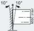 | |
| Permissible ambient temperatureOperation | °C | -25...+60; (derating from +40) |
| Storage | °C | -40...+80 |
| Degree of protection | IP20 for 3RW30 1. and 3RW30 2.;IP00 for 3RW30 3. and 3RW30 4. | |
13.1.6 3RW30 13, 14, 16, 17, 18-.BB.. power electronics
| Type | 3RW3013 | 3RW3014 | 3RW3016 | 3RW3017 | 3RW3018 | |
| Power electronics | ||||||
| Current carrying capacity rated operating current I_p | ||||||
| •Acc. to IEC and UL/CSA ^1) , for standalone assembly, AC-53a | ||||||
| -At 40°C | A | 17.612.596.53.6 | ||||
| -At 50°C | A | 3.3 | 6 | 17128 | ||
| -At 60°C | A | 3 | 5.5 | 14117 | ||
| Power loss | ||||||
| •During operation after startup of the motor at uninterrupted rated operat. curr.(40°C) approx. | W | 4210,50,25 | ||||
| •During starting at 300% I_M (40 °C) | W | 24 | 116808052 | |||
| Permissible rated motor current and starts per hourfor normal starting (class 10): | ||||||
| -Rated motor curr. I_M^2) , ramp-up time 3s | A | 3.6 / 3.3 | 6,5 / 6,0 | 9 / 8 | 12.5 / 12.0 | 17.6 / 17.0 |
| -Starts per hour ^3) | 1/h | 62 / 4685 / 7050 / 5087 / 60200 / | ||||
| -Rated motor curr. I_M^2) , ramp-up time 4s | A | 3.6 / 3.3 | 6,5 / 6,0 | 9 / 8 | 12.5 / 12.0 | 17.6 / 17.0 |
| -Starts per hour ^3) | 1/h | 45 / 3262 / 4735 / 3564 / 46150 / | ||||
| 1) Measurement at 60°C in accordance with UL/CSA not required. | 3) For intermittent duty S4 with ON time 30%, T_amb=40°C / 50°C ,vertical standalone assembly. The specified switching frequencies do notapply to automatic mode. | |||||
| 2) At 300% I_M . Tamb = 40 °C / 50 °C | ||||||
13.1.7 3RW30 26, 27, 28-.BB.. power electronics
| Type | 3RW30283RW30273RW3026 | |
| Power electronics | ||
| Current carrying capacity rated operating current I_e | ||
| •Acc. to IEC and UL/CSA1), for standalone assembly, AC-53a | ||
| -At 40°C | A | 3832.225.3 |
| -At 50°C | A | 342923 |
| -At 60°C | A | 312621 |
| Power loss | ||
| •During operation after startup of the motor at uninterrupted rated operat. curr.(40°C) approx. | W | 19138 |
| •During starting at 300% I_M(40°C) | W | 256220188 |
| Permissible rated motor current and starts per hour at normal starting (class 10) | ||
| -Rated motor curr. I_M^2 , ramp-up time 3s | A | 38 / 3432 / 2925 / 23 |
| -Starts per hour3) | 1/h | 19 / 1923 / 2323 / 23 |
| -Rated motor curr. I_M^2 , ramp-up time 4s | A | 38 / 3432 / 2925 / 23 |
| -Starts per hour3) | 1/h | 12 / 1216 / 1615 / 15 |
1) Measurement at 60°C in accordance with UL/CSA not required.
2) At 300% I_M Tamb = 40 °C / 50 °C
3) For intermittent duty S4 with ON time 30%, T_amb=40^/50^ , vertical standalone assembly. The specified switching frequencies do not apply to automatic mode. Factors for permissible switching frequency with different mounting position, direct assembly, side-by-side assembly, see Configuration chapter.
13.1.8 3RW30 36, 37, 38, 46, 47-.BB.. power electronics
| Type | 3RW3036 | 3RW3037 | 3RW3038 | 3RW3046 | 3RW3047 | |
| Power electronics | ||||||
| Current carrying capacity rated operating current I_e | ||||||
| •Acc. to IEC and UL/CSA1), for standalone assembly, AC-53a | ||||||
| -At 40°C | A | 10680726545 | ||||
| -At 50°C | A | 5842 | 987362.1 | |||
| -At 60°C | A | 9066605339 | ||||
| Power loss | ||||||
| •During operation after startup of the motor at uninterrupted rated operat. curr.(40°C)approx. | W | 211215126 | ||||
| •During starting at 300% I_M(40°C) | W | 768576500444316 | ||||
| Permissible rated motor current and starts per hour at normal starting (class 10) | ||||||
| -Rated motor curr. I_M^2) , ramp-up time 3s | A | 106 / 10880 / 7372 / 6263 / 5 | ||||
| -Starts per hour3) | 1/h | 15 / 1522 / 2222 / 2223 / 23 | ||||
| -Rated motor curr. I_M^2) , ramp-up time 4s | A | 106 / 9880 / 7372 / 6263 / 58 | ||||
| -Starts per hour3) | 1/h | 10 / 1015 / 1515 / 1515 / 15 | ||||
1) Measurement at 60°C in accordance with UL/CSA not required.
2) At 300% I M Tamb = 40 °C / 50 °C
3) For intermittent duty S4 with ON time 70%, Tamb = 40^ / 50^ , vertical standalone assembly. The specified switching frequencies do not apply to automatic mode.
13.1.9 3RW30 main conductor cross-sections
| TypeSoft starter 3RW304.3RW303.3RW302.3RW301. | ||||||
| Conductor cross-sections | ||||||
| Screw terminals | Main conductors | |||||
| Front clamping point connected | • Solid | mm^2 | 2 x (1...2.5);2 x (2.5...6)acc. to IEC 60947 | 2 x (1...2.5);2 x (2.5...6)acc. to IEC 60947;max. 1 x 10 | 2 x (2.5...16)2 x (1.5...16) | |
 | • Finely stranded with end sleeve | mm^2 | 2 x (1.5...2.5);2 x (2.5...6) | 2 x (1...2.5);2 x (2.5...6) | 1 x (2.5...35)1 x (0.75...25) | |
| • Stranded | mm^2 | - | - | 1 x (0.75...35) | 1 x (4...70) | |
| • AWG cables- Solid- Solid or stranded- Stranded | AWG | 2 x (16 ... 12)2 x (14...10) | 2 x (16 ... 12) | |||
| AWG | 1 x 8 | 1 x 8 | - | 2 x (14...10)10...2/0)1 x (18...2) | ||
| Rear clamping point connected | • Solid | mm^2 | - | - | 2 x (2.5...16)2 x (1.5...16) | |
| • Finely stranded with end sleeve | mm^2 | - | - | 1 x (2.5...50)1 x (1.5...25) | ||
| • Stranded | mm^2 | - | - | 1 x (10...70)1 x (1.5...35) | ||
 | • AWG cables- Solid or stranded | AWG | - | - | 1 x (10...2/0)1 x (16...2) | |
| Both clamping points connected | • Solid | mm^2 | - | - | 2 x (2.5...16)2 x (1.5...16) | |
| • Stranded | mm^2 | - | - | 2 x (10...50)2 x (1.5...25) | ||
| • Finely stranded with end sleeve | mm^2 | - | - | 2 x (2.5...35)2 x (1.5...16) | ||
 | • AWG cables- Solid or stranded | AWG | - | - | 2 x (16...2) | 2 x (10...1/0) |
| • Tightening torque | Nm | 6.54.52...2.52...2.5 | ||||
| lb.in | 584018...2218...22 | |||||
| Tools | PZ2PZ2PZ2 | Allen screw4 mm | ||||
| Degree of protection | IP20IP20 | IP20(terminal compartmentIP00) | IP20(terminal compartmentIP00) | |||
| Spring-loaded terminals | Main conductors | |||||
| • Solid | mm^2 | 1...4 | 1...10 | - | - | |
| • Finely stranded with end sleeve | mm^2 | 1...2.5 | 1...6; end sleeves, without plastic collar | - | - | |
| • AWG cables- Solid or stranded (finely stranded)- Stranded | AWG | 16...12 | 16...1016...141 x 8 | - | - | |
| AWG | 16...12 | 1 x 8 | - | - | ||
| Tools | DIN ISO 2380-1A0; 5 x 3 | DIN ISO 2380-1A0; 5 x 3 | - | - | ||
| Degree of protection | IP20IP20 | - | - | |||
| Busbar connections | Main conductors | |||||
| • With cable lug according to DIN 46234 or max. 20 mm wide- Stranded | mm^2 | - | - | - | 2 x (10...70) | |
| - Finely-stranded | mm^2 | - | - | - | 2 x (10...50) | |
| • AWG cables, solid or stranded | AWG | - | - | - | 2 x (7...1/0) | |
13.1.10 3RW30 auxiliary conductor cross-sections
| 3RW301....3RW304.TypeSoft starters | ||
| Conductor cross-sections | ||
| Auxiliary conductors (1 or 2 conductors can be connected): | ||
| Screw terminals | ||
| • Solid | mm^2 | 2 x (0.5...2.5) |
| • Finely stranded with end sleeve | mm^2 | 2 x (0.5...1.5) |
| • AWG cables | ||
| - Solid or stranded | AWG | 2 x (20...14) |
| - Finely stranded with end sleeve | AWG | 2 x (20...16) |
| • Terminal screws | ||
| - Tightening torque | Nm | 0.8...1.2 |
| lb.in | 7...10.3 | |
| Spring-loaded terminals | ||
| • Solid | mm^2 | 2 x (0.25...2.5) |
| • Finely stranded with end sleeve | mm^2 | 2 x (0.25...1.25) |
| • AWG cables, solid or stranded | AWG | 2 x (24...14) |
13.1.11 Electromagnetic compatibility according to EN 60947-4-2
| Standard | Parameters | |
| Electromagnetic compatibility according to EN 60947-4-2 | ||
| EMC interference immunity | ||
| Electrostatic discharge (ESD) | EN 61000-4-2 | ±4 kV contact discharge, ±8 kV air discharge |
| Electromagnetic RF fields | EN 61000-4-3 | Frequency range: 80 to 2000 MHz with 80% at 1 kHzDegree of severity 3: 10 V/m |
| Conducted RF interference | EN 61000-4-6 | Frequency range: 150 kHz...80 MHz with 80% at 1 kHzInterference 10 V |
| RF voltages and RF currents on cables | ||
| • Burst | EN 61000-4-4 | ±2 kV / 5 kHz |
| • Surge | EN 61000-4-5 | ±1 kV line to line±2 kV line to ground |
| EMC interference emission | ||
| EMC interference field strength | EN 55011 | Limit value of Class A at 30...1000 MHz,Limit value of Class B for 3RW302.; 24 V AC/DC |
| Radio interference voltage | EN 55011 | Limit value of Class A at 0.15...30 MHz,Limit value of Class B for 3RW302.; 24 V AC/DC |
| Radio interference suppression filters | ||
| Degree of noise suppression A (industrial applications) | Not required | |
| Degree of noise suppression B (applications for residential areas) | ||
| Control voltage | ||
| • 230 V AC/DC | Not available1) | |
| • 24 V AC/DC | Not required for 3RW301. and 3RW302;Required for 3RW303. and 3RW304. (see table) | |
1) Degree of noise suppression B cannot be obtained through the use of filters as the strength of the electromagnetic field is not attenuated by the filter.
13.1.12 Recommended filters
| Soft starter types | Nominal current Soft starter | Recommended filters ^1) | ||
| Voltage range 200 to 480 V | ||||
| A | A | TerminalsNominal current filtersFilter types mm^2 | ||
| 3RW30 36 | 45 | 4EF1512-1AA10 | 50 | 16 |
| 3RW30 37 | 63 | 4EF1512-2AA10 | 66 | 25 |
| 3RW30 38 | 72 | 4EF1512-3AA10 | 90 | 25 |
| 3RW30 46 | 80 | 4EF1512-3AA10 | 90 | 25 |
| 3RW30 47 | 106 | 4EF1512-4AA10 | 120 | 50 |
1) The radio interference suppression filter is used to remove the conducted interference from the main circuit. The field-related emissions comply with degree of noise suppression B. The filter should be selected under standard conditions: 10 starts per hour, ramp-up time 4 s at 300% I_e
13.1.13 Types of coordination
Types of coordination
The type of coordination according to which the motor feeder with soft starter is mounted depends on the application-specific requirements. Normally, fuseless mounting (combination of motor starter protector and soft starter) is sufficient.
If type of coordination 2 needs to be fulfilled, semiconductor fuses must be fitted in the motor feeder.
Type of coordination 1 in accordance with IEC 60947-4-1:
The device is defective following a short-circuit failure and therefore unsuitable for further use. (Personnel and equipment must not be put at risk).
Type of coordination 2 in accordance with IEC 60947-4-1:
The device is suitable for further use following a short-circuit failure. (Personnel and equipment must not be put at risk).
The type of coordination only refers to soft starters in conjunction with the stipulated protective device (motor starter protector / fuse), not to additional components in the feeder.
13.1.14 Fuseless version
| Fuseless version | |||||
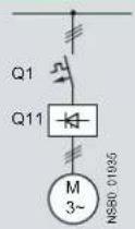 | |||||
| Soft startersTCC1Q11 | Nominal currentAType | Motor starter protectors1)400 V +10%Q1Type | Iq maxkA | Rated currentA | |
| Type of coordination 12) | |||||
| 3RW30 03 | 3 | 3RV1011-1EA10 | 3RV20 11-1EA (provis.) | 50 | 4 |
| 3RW30 13 | 3.6 | 3RV1021-1FA10 | 3RV20 11-1FA | 10 | 5 |
| 3RW30 14 | 6.5 | 3RV1021-1HA10 | 3RV20 11-1HA | 10 | 8 |
| 3RW30 16 | 9 | 3RV1021-1JA10 | 3RV20 11-1JA | 10 | 10 |
| 3RW30 17 | 12.5 | 3RV1021-1KA10 | 3RV20 11-1KA | 10 | 12.5 |
| 3RW30 18 | 17.6 | 3RV1021-4BA10 | 3RV20 21-4BA | 10 | 20 |
| 3RW30 26 | 25 | 3RV1021-4DA10 | 3RV20 21-4DA | 55 | 25 |
| 3RW30 27 | 32 | 3RV1031-4EA10 | 3RV20 21-4EA | 55 | 32 |
| 3RW30 28 | 38 | 3RV1031-4FA10 | 3RV20 21-4FA | 55 | 40 |
| 3RW30 36 | 45 | 3RV1031-4GA10 | 20 | 45 | |
| 3RW30 37 | 63 | 3RV1041-4JA10 | 20 | 63 | |
| 3RW30 38 | 72 | 3RV1041-4KA10 | 20 | 75 | |
| 3RW30 46 | 80 | 3RV1041-4LA10 | 11 | 90 | |
| 3RW30 47 | 106 | 3RV1041-4MA10 | 11 | 100 | |
| 1) The rated motor current must be considered when selecting the devices. | 2) The types of coordination are described in chapter Types of coordination [Page 128]. | ||||
13.1.15 Fused version (line protection only)
| Fused version (line protection only) | ||||||
| F1 Q21 Q11 M 3~ NS80 01996 | ||||||
| Soft starters 1 | Nominal current | Line protection, maximum=Line contactors | ||||
| F1Q11=Q21 | current ATypeAType | SizeRated (optional) | ||||
| Type of coordination 1): Iq = 65 kA at 480 V + 10% | ||||||
| 3RW30 032) | 3 | 3NA38053) | 20 | 000 | 3RT10 15 | 3RT20 15 |
| 3RW30 13 | 3.6 | 3NA3803-6 | 10 | 000 | 3RT10 15 | 3RT20 15 |
| 3RW30 14 | 6.5 | 3NA3805-6 | 16 | 000 | 3RT10 15 | 3RT20 15 |
| 3RW30 16 | 9 | 3NA3807-6 | 20 | 000 | 3RT10 16 | 3RT20 16 |
| 3RW30 17 | 12.5 | 3NA3810-6 | 25 | 000 | 3RT10 24 | 3RT20 18 |
| 3RW30 18 | 17.6 | 3NA3814-6 | 35 | 000 | 3RT10 26 | 3RT20 26 |
| 3RW30 26 | 25 | 3NA3822-6 | 63 | 00 | 3RT10 26 | 3RT20 26 |
| 3RW30 27 | 32 | 3NA3824-6 | 80 | 00 | 3RT10 34 | 3RT20 27 |
| 3RW30 28 | 38 | 3NA3824-6 | 80 | 00 | 3RT10 35 | 3RT20 28 |
| 3RW30 36 | 45 | 3NA3130-6 | 100 | 1 | 3RT10 36 | |
| 3RW30 37 | 63 | 3NA3132-6 | 125 | 1 | 3RT10 44 | |
| 3RW30 38 | 72 | 3NA3132-6 | 125 | 1 | 3RT10 45 | |
| 3RW30 46 | 80 | 3NA3136-6 | 160 | 1 | 3RT10 45 | |
| 3RW30 47 | 106 | 3NA3136-6 | 160 | 1 | 3RT10 46 | |
1) The types of coordination are described in chapter 1 types of coordination [Page 128]. Type of coordination 1 only refers to soft starters in conjunction with the stipulated protective device (motor starter protector / fuse), not to any additional components in the feeder.
2) I_q = 50 kA at 400 V.
3) 3NA3 805-1 (NH00), 5SB2 61 (DIAZED), 5SE2 201-6 (NEOZED).
13.1.16 Fused version with SITOR 3NE1 fuses
Assembly as for type of coordination 2, with SITOR all-range fuses (F'1) for combined thyristor and line protection.
| Fused version with SITOR 3NE1 fuses (semiconductor and line protection) | ||||||
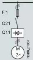 | For suitable fuse bases, refer to "SENTRON switching and protecting devices for power distribution"→"Switch disconnectors" in the LV1 Catalog and to "BETA protecting"→"SITOR semiconductor fuses" the ET B1 Catalog or consult www.siemens.de/sitor | |||||
| Standard | Nominal current | All-range fusesSoft starters=Line contactors | (optional) | |||
| F'1Q11 TypeAType | Rated current A | Size | Q21 | |||
| Type of coordination 2^1) : L_q = 65 kA at 480 V + 10% | ||||||
| 3RW30 03^2) | 3 | 3NE1813-0^3) | 16 | 000 | 3RT10 15 | 3RT20 15 |
| 3RW30 13 | 3.6 | 3NE1813-0 | 16 | 000 | 3RT10 15 | 3RT20 15 |
| 3RW30 14 | 6.5 | 3NE1813-0 | 16 | 000 | 3RT10 15 | 3RT20 15 |
| 3RW30 16 | 9 | 3NE1813-0 | 16 | 000 | 3RT10 16 | 3RT20 16 |
| 3RW30 17 | 12.5 | 3NE1813-0 | 16 | 000 | 3RT10 24 | 3RT20 18 |
| 3RW30 18 | 17.6 | 3NE1814-0 | 20 | 000 | 3RT10 26 | 3RT20 26 |
| 3RW30 26 | 25 | 3NE1803-0 | 35 | 000 | 3RT10 26 | 3RT20 26 |
| 3RW30 27 | 32 | 3NE1020-2 | 80 | 00 | 3RT10 34 | 3RT20 27 |
| 3RW30 28 | 38 | 3NE1020-2 | 80 | 00 | 3RT10 35 | 3RT20 28 |
| 3RW30 36 | 45 | 3NE1020-2 | 80 | 00 | 3RT10 36 | |
| 3RW30 37 | 63 | 3NE1820-0 | 80 | 000 | 3RT10 44 | |
| 3RW30 38 | 72 | 3NE1820-0 | 80 | 000 | 3RT10 45 | |
| 3RW30 46 | 80 | 3NE1021-0 | 100 | 00 | 3RT10 45 | |
| 3RW30 47 | 106 | 3NE1022-0 | 125 | 00 | 3RT10 46 | |
1) The types of coordination are described in chapter Types of coordination [Page 128]. Type of coordination 2 only refers to soft starters in conjunction with the stipulated protective device (motor starter protector / fuse), not to additional components in the feeder.
2) I_q = 50 kA at 400 V.
3) No SITOR fuse required!
Alternatively: 3NA3 803 (NH00), 5SB2 21 (DIAZED), 5SE2 206 (NEOZED)
13.1.17 Fused version with SITOR 3NE3/4/8 fuses
Assembly as for type of coordination 2, with additional SITOR fuses (F3) for thyristor protection only.
| Fused version with 3NE3 SITOR fuses (semiconductor protection by fuse, line, and overload protection by motor starter protector; alternatively, installation with contactor and overload relay possible) | |||||||||||
| F3Q11TypeAType | F1Q21F3Q11M3~N550_01699 | For suitable fuse bases, refer to "SENTRON switching and protecting devices for power distribution" → "Switch disconnectors" the LV1 Catalog and to "BETA protecting" → "SITOR semiconductor fuses" in the ET B1 Catalog or consult www.siemens.de/sitor | |||||||||
| Soft starters ^1/2 | Nominal current | Rated current=Size=Rated current | Size | Semiconductor fuses, minimumSemiconductor fuses, maximum | |||||||
| F3Q11TypeAType | A=AType | F3 | AType | F3 | Rated current | Size | |||||
| Type of coordination 2^1) : I_q = 65 kA at 480 V + 10% | |||||||||||
| 3RW30 03 ^2) | 3 | - | - | - | - | - | |||||
| 3RW30 13 | 3.6 | - | - | - | - | - | - | 3NE4101 | 32 | 0 | |
| 3RW30 14 | 6.5 | - | - | - | - | - | - | 3NE4101 | 32 | 0 | |
| 3RW30 16 | 9 | - | - | - | - | - | - | 3NE4101 | 32 | 0 | |
| 3RW30 17 | 12.5 | - | - | - | - | - | - | 3NE4101 | 32 | 0 | |
| 3RW30 18 | 17.6 | - | - | - | 3NE3221 | 100 | 1 | 3NE4101 | 32 | 0 | |
| 3RW30 26 | 25 | - | - | - | 3NE3221 | 100 | 1 | 3NE4102 | 40 | 0 | |
| 3RW30 27 | 32 | - | - | - | 3NE3222 | 125 | 1 | 3NE4118 | 63 | 0 | |
| 3RW30 28 | 38 | - | - | - | 3NE3222 | 125 | 1 | 3NE4118 | 63 | 0 | |
| 3RW30 36 | 45 | - | - | - | 3NE3224 | 160 | 1 | 3NE4120 | 80 | 0 | |
| 3RW30 37 | 63 | - | - | - | 3NE3225 | 200 | 1 | 3NE4121 | 100 | 0 | |
| 3RW30 38 | 72 | 3NE3221 | 100 | 1 | 3NE3227 | 250 | 1 | - | - | - | |
| 3RW30 46 | 80 | 3NE3222 | 125 | 1 | 3NE3225 | 200 | 1 | - | - | - | |
| 3RW30 47 | 106 | 3NE3224 | 160 | 1 | 3NE3231 | 350 | 1 | - | - | - | |
| Soft starters ^1/2 | Nominal current | Semiconductor fuses, max. | Semiconductor fuses, min. | Semiconductor fuses, max. | Cylindrical fuses | ||||||
| Rated current | Size | Rated current | Size | Rated current | Size | Rated current | |||||
| Q11 Type | A | F3 Type | A | F3 Type | A | F3 Type | A | F3 Type | A | F3 Type | A |
| Type of coordination 2^1) : I_q = 65 kA at 480 V + 10% | |||||||||||
| 3RW30 03 ^2) | 3 | - | - | - | 3NE8015-1 | 25 | 00 | 3NE8015-1 | 25 | 00 | 3NC1010 10 |
| 3RW30 13 | 3.6 | - | - | - | 3NE8015-1 | 25 | 00 | 3NE8015-1 | 25 | 00 | 3NC2220 20 |
| 3RW30 14 | 6.5 | - | - | - | 3NE8015-1 | 25 | 00 | 3NE8015-1 | 25 | 00 | 3NC2220 20 |
| 3RW30 16 | 9 | - | - | - | 3NE8015-1 | 25 | 00 | 3NE8015-1 | 25 | 00 | 3NC2220 20 |
| 3RW30 17 | 12.5 | - | - | - | 3NE8015-1 | 25 | 00 | 3NE8018-1 | 63 | 00 | 3NC2250 50 |
| 3RW30 18 | 17.6 | - | - | - | 3NE8003-1 | 35 | 00 | 3NE8021-1 | 100 | 00 | 3NC2263 63 |
| 3RW30 26 | 25 | 3NE4117 | 50 | 0 | 3NE8017-1 | 50 | 00 | 3NE8021-1 | 100 | 00 | 3NC2263 63 |
| 3RW30 27 | 32 | 3NE4118 | 63 | 0 | 3NE8018-1 | 63 | 00 | 3NE8022-1 | 125 | 00 | 3NC2280 80 |
| 3RW30 28 | 38 | 3NE4118 | 63 | 0 | 3NE8020-1 | 80 | 00 | 3NE8022-1 | 125 | 00 | 3NC2280 80 |
| 3RW30 36 | 45 | 3NE4120 | 80 | 0 | 3NE8020-1 | 80 | 00 | 3NE8024-1 | 160 | 00 | 3NC2280 80 |
| 3RW30 37 | 63 | 3NE4121 | 100 | 0 | 3NE8021-1 | 100 | 00 | 3NE8024-1 | 160 | 00 | - |
| 3RW30 38 | 72 | - | - | - | 3NE8022-1 | 125 | 00 | 3NE8024-1 | 160 | 00 | - |
| 3RW30 46 | 80 | - | - | - | 3NE8022-1 | 125 | 00 | 3NE8024-1 | 160 | 00 | - |
| 3RW30 47 | 106 | - | - | - | 3NE8024-1 | 160 | 00 | 3NE8024-1 | 160 | 00 | - |
| Soft starters 10c2 Type | Nominal currentA | Line contactors | Motor starter protectors400 V +10%(optional) | Rated currentA | Line protection, maximum | ||||
| F1Q1Q21Q11 Type | Rated currentA | Size | |||||||
| Type | |||||||||
| Type of coordination 2^1) : I_q = 65 kA at 480 V + 10% | |||||||||
| 3RW30 03^2) | 3 | 3RT10 15 | 3RT20 15 | 3RV1011-1EA10 | 3RV20 11-1EA (provis.) | 4 | 3NA3805^3) | 20 | 000 |
| 3RW30 13 | 3.6 | 3RT10 15 | 3RT20 15 | 3RV1021-1FA10 | 3RV20 11-1FA | 5 | 3NA3803-6 | 10 | 000 |
| 3RW30 14 | 6.5 | 3RT10 15 | 3RT20 15 | 3RV1021-1HA10 | 3RV20 11-1HA | 8 | 3NA3805-6 | 16 | 000 |
| 3RW30 16 | 9 | 3RT10 16 | 3RT20 16 | 3RV1021-1JA10 | 3RV20 11-1JA | 10 | 3NA3807-6 | 20 | 000 |
| 3RW30 17 | 12.5 | 3RT10 24 | 3RT20 18 | 3RV1021-1KA10 | 3RV20 11-1KA | 12.5 | 3NA3810-6 | 25 | 000 |
| 3RW30 18 | 17.6 | 3RT10 26 | 3RT20 26 | 3RV1021-1BA10 | 3RV20 21-4BA | 20 | 3NA3814-6 | 35 | 000 |
| 3RW30 26 | 25 | 3RT10 26 | 3RT10 26 | 3RV1031-4DA10 | 3RV20 21-4DA | 25 | 3NA3822-6 | 63 | 00 |
| 3RW30 27 | 32 | 3RT10 34 | 3RT20 27 | 3RV1031-4EA10 | 3RV20 21-4EA | 32 | 3NA3824-6 | 80 | 00 |
| 3RW30 28 | 38 | 3RT10 35 | 3RT20 28 | 3RV1031-4EA10 | 3RV20 21-4FA | 40 | 3NA3824-6 | 80 | 00 |
| 3RW30 36 | 45 | 3RT10 36 | 3RV1031-4GA10 | 45 | 3NA3130-6 | 100 | 1 | ||
| 3RW30 37 | 63 | 3RT10 44 | 3RV1041-4JA10 | 63 | 3NA3132-6 | 125 | 1 | ||
| 3RW30 38 | 72 | 3RT10 45 | 3RV1041-4KA10 | 75 | 3NA3132-6 | 125 | 1 | ||
| 3RW30 46 | 80 | 3RT10 45 | 3RV1041-4LA10 | 90 | 3NA3136-6 | 160 | 1 | ||
| 3RW30 47 | 106 | 3RT10 46 | 3RV1041-4MA10 | 100 | 3NA3136-6 | 160 | 1 | ||
1) The types of coordination are described in 2) I_q = 50 kA at 400 V. chapter I types of coordination [Page 128].
Type of coordination 2 only refers to soft starters in conjunction with the stipulated protective device (motor starter protector / fuse), not to additional components in the feeder.
13.2 3RW40
13.2.1 Overview
SIRIUS 3RW40 soft starters have all the same advantages as the 3RW30 soft starters.
SIRIUS 3RW40 soft starters are characterized above all by their small space requirements. Integral bypass contacts mean that no power loss has to be taken into account at the power semiconductors (thyristors) after the motor has started up. This cuts down on heat losses, enabling a more compact design and making external bypass circuits superfluous.
At the same time, this soft starter comes with additional integrated functions such as settable current limiting, motor overload and intrinsic device protection, and optional thermistor motor protection. The higher the motor rating, the more important these functions become because they make it unnecessary to purchase and install protection equipment (such as overload relays).
Internal intrinsic device protection prevents thermal overloading of the thyristors and the power unit defects this can cause. As an option, the thyristors can also be protected against short-circuiting with semiconductor fuses.
Thanks to integrated status and fault monitoring, this compact soft starter offers many different diagnostics options. Up to four LEDs and relay outputs permit differentiated monitoring and diagnostics of the operating mechanism by indicating the operating state as well as, for example, mains or phase failures, missing load, impermissible tripping times / CLASS settings, thermal overloading, or device faults.
Soft starters rated up to 250 kW (at 400 V) can be supplied for standard applications in three-phase systems. Extremely small sizes, low power losses, and simple commissioning are just three of the many advantages of the SIRIUS 3RW40 soft starters.
"Increased safety" type of protection EEx e according to ATEX Directive 94/9/EC
The SIRIUS 3RW40 soft starter sizes S0 to S12 are suitable for starting explosion-proof motors with the "increased safety" type of protection EEx e.
13.2.2 Selection and ordering data for standard applications and normal starting (CLASS 10)
3RW40 28-1BB14
3RW40 38-1BB14 3RW40 47-1BB14
| Ambient temperature 40°C | Ambient temperature 50°C | Size | Normal starting | ||||||
| Rated operational current I_e^1) | Rated power of three-phase induction motors for rated operational voltage U_e | Rated operational current I_e^1) | Rated power of three-phase induction motors for rated operational voltage U_e | ||||||
| 500 V400 V230 V | 575 V460 V230 V200 | Order No. | |||||||
| A | kW | kW | kW | A | hp | hp | hp | ||
Rated operational voltage U_e 200 to 480 V ^2)
| • With screw or spring-loaded terminals | |||||||||
| 12.5 | 3 | 5.5 | - | 11 | 3 | 3 | 7.5 | - | S0 |
| 25 | 5.5 | 11 | - | 23 | 5 | 5 | 15 | - | S0 |
| 32 | 7.5 | 15 | - | 29 | 7.5 | 7.5 | 20 | - | S0 |
| 38 | 11 | 18.5 | - | 34 | 10 | 10 | 25 | - | S0 |
| • With screw or spring-loaded terminals | |||||||||
| 45 | 11 | 22 | - | 42 | 10 | 15 | 30 | - | S2 |
| 58 | 18.5 | 30 | - | 58 | 15 | 20 | 40 | - | S2 |
| 72 | 22 | 37 | - | 62 | 20 | 20 | 40 | - | S2 |
| • With screw or spring-loaded terminals | |||||||||
| 80 | 22 | 45 | - | 73 | 20 | 25 | 50 | - | S3 |
| 106 | 30 | 55 | - | 98 | 30 | 30 | 75 | - | S3 |
Rated operational voltage U_e 400 to 600 V ^2)
| • With screw or spring-loaded terminals | |||||||||
| 12.5 | - | 5.5 | 7.5 | 11 | - | - | 7.5 | 10 | S0 |
| 25 | - | 11 | 15 | 23 | - | - | 15 | 20 | S0 |
| 32 | - | 15 | 18.5 | 29 | - | - | 20 | 25 | S0 |
| 38 | - | 18.5 | 22 | 34 | - | - | 25 | 30 | S0 |
| • With screw or spring-loaded terminals | |||||||||
| 45 | - | 22 | 30 | 42 | - | - | 30 | 40 | S2 |
| 58 | - | 30 | 37 | 58 | - | - | 40 | 50 | S2 |
| 72 | - | 37 | 45 | 62 | - | - | 40 | 60 | S2 |
| • With screw or spring-loaded terminals | |||||||||
| 80 | - | 45 | 55 | 73 | - | - | 50 | 60 | S3 |
| 106 | - | 55 | 75 | 98 | - | - | 75 | 75 | S3 |
Order number supplement for connection types
- With screw terminals
- With spring-loaded terminals ^3)
Order number supplement for rated control supply voltage U_s
• 24 V AC/DC
• 110 to 230 V AC/DC
1) Standalone assembly without additional fan.
2) Soft starter with screw terminals.
^3) Main circuit connection: screw terminals.
Note
The rated motor current is extremely important when selecting a soft starter.
Refer to the information about selecting soft starters in chapter Configuration [Page 73].
Conditions for normal starting (CLASS 10):
Max. ramp-up time 10 s, current limiting 300 %, 5 starts / hour, ON time 30 %, standalone assembly, max. installation altitude 1000 m / 3280 ft, ambient temperature kW 40 °C / 104 °F. A larger model may need to be selected if other conditions and constraints apply or for a higher starting frequency. We recommend using the "Win-Soft Starter" selection and simulation software. For information about the rated currents for ambient temperatures > 40 °C, refer to chapter 3RW40 2. to 7. power electronics [Page 148].
13.2.3 Selection and ordering data for standard applications and normal starting (CLASS 10) (with thermistor motor protection evaluation)
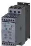
3RW40 28-1TB04
3RW40 38-1TB04 3RW40 47-1TB04
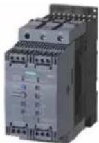
| Ambient temperature 40°C | Ambient temperature 50°C | Size | Normal starting (CLASS 10) | ||||||
| Rated operational current I_e^1) | Rated power of three-phase induction motors for rated operational voltage U_e | Rated operational current I_e^1) | Rated power of three-phase induction motors for rated operational voltage U_e | ||||||
| 500 V400 V230 V | 575 V460 V230 V200 | Order No. | |||||||
| A | kW | kW kW | A | hp | hp hp hp | ||||
Rated operational voltage U_e 200 to 480 V ^2) , with thermistor motor protection, rated control supply voltage U_s 24 V AC/DC
| • With screw or spring-loaded terminals | |||||||||
| 12.5 | 3 | 5.5 | - | 11 | 3 | 3 | 7.5 | - | S0 |
| 25 | 5.5 | 11 | - | 23 | 5 | 5 | 15 | - | S0 |
| 32 | 7.5 | 15 | - | 29 | 7.5 | 7.5 | 20 | - | S0 |
| 38 | 11 | 18.5 | - | 34 | 10 | 10 | 25 | - | S0 |
| • With screw or spring-loaded terminals | |||||||||
| 45 | 11 | 22 | - | 42 | 10 | 15 | 30 | - | S2 |
| 63 | 18.5 | 30 | - | 58 | 15 | 20 | 40 | - | S2 |
| 72 | 22 | 37 | - | 62 | 20 | 20 | 40 | - | S2 |
| • With screw or spring-loaded terminals | |||||||||
| 80 | 22 | 45 | - | 73 | 20 | 25 | 50 | - | S3 |
| 106 | 30 | 55 | - | 98 | 30 | 30 | 75 | - | S3 |
Rated operational voltage U_e 400 to 600 V, with thermistor motor protection, rated control supply voltage U_s 24 V AC/DC
| • With screw or spring-loaded terminals | ||||||||||
| 12.5 | - | 5.5 | 7.5 | 11 | - | - | 7.5 | 10 | S0 | 3RW40 24-□TB05 |
| 25 | - | 11 | 15 | 23 | - | - | 15 | 20 | S0 | 3RW40 26-□TB05 |
| 32 | - | 15 | 18.5 | 29 | - | - | 20 | 25 | S0 | 3RW40 27-□TB05 |
| 38 | - | 18.5 | 22 | 34 | - | - | 25 | 30 | S0 | 3RW40 28-□TB05 |
| • With screw or spring-loaded terminals | ||||||||||
| 45 | - | 22 | 30 | 42 | - | - | 30 | 40 | S2 | 3RW40 36-□TB05 |
| 63 | - | 30 | 37 | 58 | - | - | 40 | 50 | S2 | 3RW40 37-□TB05 |
| 72 | - | 37 | 45 | 62 | - | - | 40 | 60 | S2 | 3RW40 38-□TB05 |
| • With screw or spring-loaded terminals | ||||||||||
| 80 | - | 45 | 55 | 73 | - | - | 50 | 60 | S3 | 3RW40 46-□TB05 |
| 106 | - | 55 | 75 | 98 | - | - | 75 | 75 | S3 | 3RW40 47-□TB05 |
Order number supplement for connection types
- With screw terminals
- With spring-loaded terminals ^3)
1) Standalone assembly without additional fan.
2) Soft starter with screw terminals.
3) Main circuit connection: screw terminals.
Note
The rated motor current is extremely important when selecting a soft starter.
Refer to the information about selecting soft starters in chapter Configuration [Page 73].
Conditions for normal starting (CLASS 10):
Max. ramp-up time 10 s, current limiting 300 %, 5 starts / hour, ON time 30 %, standalone assembly, max. installation altitude 1000 m / 3280 ft, ambient temperature kW 40 °C / 104 °F. A larger model may need to be selected if other conditions and constraints apply or for a higher starting frequency. We recommend using the "Win-Soft Starter" selection and simulation software. For information about the rated currents for ambient temperatures > 40 °C, refer to chapter 3RW40 2. to 7. power electronics [Page 148].
13.2.4 Selection and ordering data for standard applications and normal starting (CLASS 10)
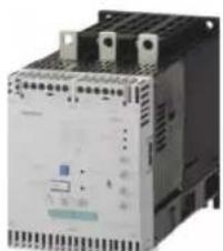
natural_image
Industrial control unit with mounting flanges and indicator lights (no visible text or symbols)3RW40 56-6BB44
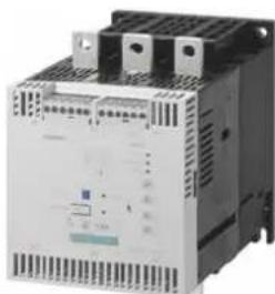
natural_image
Exterior view of a white industrial electrical contactor device (no visible text or symbols)3RW40 76-6BB44
| Ambient temperature 40°C | Ambient temperature 50°C | Size | Normal starting (CLASS 10) | ||||||
| Rated operational current I_e^1) | Rated power of three-phase induction motors for rated operational voltage U_e | Rated operational current I_e^1) | Rated power of three-phase induction motors for rated operational voltage U_e | ||||||
| 500 V400V230 V | 575 V460 V230 V200 | ||||||||
| A | kW | kW kW | A | hp | hp | hp | hp | Order No. | |
Rated operational voltage U_e 200 to 460 V ^2)
| • With screw or spring-loaded terminals | |||||||||
| 134 | 37 | 75 | - | 117 | 30 | 40 | 75 | - | S6 |
| 162 | 45 | 30 | - | 145 | 40 | 50 | 100 | - | |
| • With screw or spring-loaded terminals | |||||||||
| 230 | 75 | 132 | - | 205 | 60 | 75 | 150 | - | S12 |
| 280 | 90 | 160 | - | 248 | 75 | 100 | 200 | - | |
| 356 | 110 | 200 | - | 315 | 100 | 125 | 250 | - | |
| 432 | 132 | 250 | - | 385 | 125 | 150 | 300 | - | |
Rated operational voltage U_e 400 to 600 V ^2)
| • With screw or spring-loaded terminals | |||||||||
| 134 | - | 75 | 90 | 117 | - | - | 75 | 100 | S6 |
| 162 | - | 90 | 110 | 145 | - | - | 100 | 150 | |
| • With screw or spring-loaded terminals | |||||||||
| 230 | - | 132 | 160 | 205 | - | - | 150 | 200 | S12 |
| 280 | - | 160 | 200 | 248 | - | - | 200 | 250 | |
| 356 | - | 200 | 250 | 315 | - | - | 250 | 300 | |
| 432 | - | 250 | 315 | 385 | - | - | 300 | 400 | |
Order number supplement for connection types ^3)
- With spring-loaded terminals
- With screw terminals
Order number supplement for rated control supply voltage U_s^4)
• 115 V AC
· 230 V AC
1) Standalone assembly.
2) Soft starter with screw terminals.
3) Main circuit connection: busbar connection.
4) Control by way of the internal 24 V DC supply or direct control by means of PLC possible
Note
The rated motor current is extremely important when selecting a soft starter.
Refer to the information about selecting soft starters in chapter Configuration [Page 73].
Conditions for normal starting (CLASS 10):
Max. ramp-up time 10 s, current limiting 300 %, 5 starts / hour, ON time 30 %, standalone assembly, max. installation altitude 1000 m / 3280 ft, ambient temperature kW 40°C / 104 °F. A larger model may need to be selected if other conditions and constraints apply or for a higher starting frequency. We recommend using the "Win-Soft Starter" selection and simulation software. For information about the rated currents for ambient temperatures > 40 °C, refer to chapter 3RW40 2. to 7. power electronics [Page 148].
13.2.5 Selection and ordering data for standard applications and heavy-duty starting (CLASS 20)
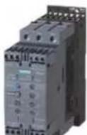
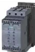
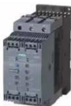
3RW40 28-1BB14 3RW40 28-1TB04 3RW40 38-1TB043RW40 38-1BB14 3RW40 47-1TB043RW40 47-1BB14
| Ambient temperature 40°C | Ambient temperature 50°C | Size | Heavy-duty starting (CLASS 20) | ||||||
| Rated operational current I_e^(1) | Rated power of three-phase induction motors for rated operational voltage U_e | Rated operational current I_e^(1) | Rated power of three-phase induction motors for rated operational voltage U_e | ||||||
| 500 V400 V230 V | 575 V460 V230 V200 | ||||||||
| A | kW | kW kW | A | hp | hp | hp | hp | Order No. | |
Rated operational voltage U_e 200 to 480 V ^2)
| • With screw or spring-loaded terminals | |||||||||
| 12.5 | 3 | 5.5 | - | 11 | 3 | 3 | 7.5 | - | S0 |
| 25 | 5.5 | 11 | - | 23 | 5 | 5 | 15 | - | S0 |
| 32 | 7.5 | 15 | - | 29 | 7.5 | 7.5 | 20 | - | S2 |
| 38 | 11 | 18.5 | - | 34 | 10 | 10 | 25 | - | S2 |
| 45 | 11 | 22 | - | 42 | 10 | 15 | 30 | - | S2 |
| 63 | 18.5 | 30 | - | 58 | 15 | 20 | 40 | - | S3 |
| 72 | 22 | 37 | - | 62 | 20 | 20 | 40 | - | S3 |
Rated operational voltage U _e 400 to 600 V
| • With screw or spring-loaded terminals | |||||||||
| 12.5 | - | 5.5 | 7.5 | 11 | - | - | 7.5 | 10 | S0 |
| 25 | - | 11 | 15 | 23 | - | - | 15 | 20 | S0 |
| 32 | - | 15 | 18.5 | 29 | - | - | 20 | 25 | S2 |
| 38 | - | 18.5 | 22 | 34 | - | - | 25 | 30 | S2 |
| 45 | - | 22 | 30 | 42 | - | - | 30 | 40 | S2 |
| 63 | - | 30 | 37 | 58 | - | - | 40 | 50 | S3 |
| 72 | - | 37 | 45 | 62 | - | - | 40 | 60 | S3 |
Order number supplement for connection types
- With screw terminals
- With spring-loaded terminals ^3)
Order number supplement for thermistor motor protection
- Standard function
•Thermistor motor protection only with rated control supply voltage U _s 24 V AC/DC
Order number supplement for rated control supply voltage U_s
• 24 V AC/DC
110...230 V AC/DC
^1) Standalone assembly without additional fan.
2) Soft starter with screw terminals.
3) Main circuit connection: screw terminals.
Note
The rated motor current is extremely important when selecting a soft starter.
Refer to the information about selecting soft starters in chapter Configuration [Page 73].
Conditions for normal starting (CLASS 10):
Max. ramp-up time 20 s, current limiting 300 %, 5 starts / hour, ON time 30 %, standalone assembly, max. installation altitude 1000 m / 3280 ft, ambient temperature kW 40 °C / 104°. A larger model may need to be selected if other conditions and constraints apply or for a higher starting frequency. We recommend using the "Win-Soft Starter" selection and simulation software. For information about the rated currents for ambient temperatures > 40 °C, refer to chapter 3RW40 24, 26, 27, 28 power electronics [Page 149].
13.2.6 Selection and ordering data for standard applications and heavy-duty starting (CLASS 20)
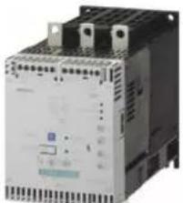
natural_image
Industrial control unit with buttons and indicator lights (no visible text or symbols)3RW40 56-6BB44
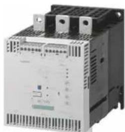
natural_image
Exterior view of a white industrial electrical component with cooling fins and mounting holes (no visible text or symbols)3RW40 76-6BB44
| Ambient temperature 40°C | Ambient temperature 50°C | Size | Heavy-duty starting (CLASS 20) | ||||||
| Rated operational current I_e^1) | Rated power of three-phase induction motors for rated operational voltage U_e | Rated operational current I_e^1) | Rated power of three-phase induction motors for rated operational voltage U_e | ||||||
| Order No. | |||||||||
| A | kW | kW | kW | A | hp | hp | hp | hp | |
Rated operational voltage U_e 200 to 460 V ^2)
| With screw or spring-loaded terminals | |||||||||
| 80 | 22 | 45 | - | 73 | 20 | 25 | 50 | - | S6 |
| 106 | 30 | 55 | - | 98 | 25 | 30 | 60 | - | S6 |
| 134 | 37 | 75 | - | 117 | 30 | 40 | 75 | - | S6 |
| 162 | 45 | 90 | - | 145 | 40 | 50 | 100 | - | S12 |
| 230 | 75 | 132 | - | 205 | 60 | 75 | 150 | - | S12 |
| 280 | 90 | 160 | - | 248 | 75 | 100 | 200 | - | S12 |
| 356 | 110 | 200 | - | 315 | 100 | 125 | 250 | - | S12 |
Rated operational voltage U_e 400 to 600 V ^2)
| With screw or spring-loaded terminals | ||||||||||
| 80 | - | 45 | 55 | 73 | - | - | 50 | 60 | S6 | 3RW40 55-□BB□5 |
| 106 | - | 55 | 75 | 98 | - | - | 60 | 75 | S6 | 3RW40 55-□BB□5 |
| 134 | - | 75 | 90 | 117 | - | - | 75 | 100 | S6 | 3RW40 56-□BB□5 |
| 162 | - | 90 | 110 | 145 | - | - | 100 | 150 | S12 | 3RW40 73-□BB□5 |
| 230 | - | 132 | 160 | 205 | - | - | 150 | 200 | S12 | 3RW40 74-□BB□5 |
| 280 | - | 160 | 200 | 248 | - | - | 200 | 250 | S12 | 3RW40 75-□BB□5 |
| 356 | - | 200 | 250 | 315 | - | - | 250 | 300 | S12 | 3RW40 76-□BB□5 |
Order number supplement for connection types ^3)
- With spring-loaded terminals
- With screw terminals
Order number supplement for rated control supply voltage U_s^4)
· 115 V AC
• 230 V AC
1) Standalone assembly.
2) Soft starter with screw terminals.
3) Main circuit connection: busbar connection.
4) Control by way of the internal 24 V DC supply or direct control by means of PLC possible
Note
The rated motor current is extremely important when selecting a soft starter.
Refer to the information about selecting soft starters in chapter Configuration [Page 73].
Conditions for normal starting (CLASS 10):
Max. ramp-up time 40 s, current limiting 350 %, 1 starts / hour, ON time 30 %, standalone assembly, max. installation altitude 1000 m / 3280 ft, ambient temperature kW 40 °C / 104 °F. A larger model may need to be selected if other conditions and constraints apply or for a higher starting frequency. We recommend using the "Win-Soft Starter" selection and simulation software. For information about the rated currents for ambient temperatures > 40 °C, refer to chapter 3RW40 55, 56, 73, 74, 75, 76 power electronics [Page 151].
13.2.7 3RW40 2., 3., 4. control electronics
| Type | 3RW403., 3RW404.3RW402. | ||||||
| Control electronics | |||||||
| Rated values | Terminal | ||||||
| Rated control supply voltage | A1 / A2 | V | 24 | 110...230 | 24 | 110...230 | |
| • Tolerance | % | ±20 | -15/+10 | ±20 | -15/+10 | ||
| Rated control supply current | |||||||
| • STANDBY | mA | <150 | <50 | <200 | <50 | ||
| • During pickup | mA | <200 | <100 | <5000 | <1500 | ||
| • ON without fan | mA | <250 | <50 | <200 | <50 | ||
| • ON with fan | mA | <300 | <70 | <250 | <70 | ||
| Rated frequency | Hz | 50/60 | |||||
| • Tolerance | % | ±20 | |||||
| Control inputsIN | ON / OFF | ||||||
| Rated operational current | |||||||
| • AC | mA | 3/6Approx. 123/6Approx. 12 | |||||
| • DC | mA | 1.5/3Approx. 121.5/3Approx. 12 | |||||
| Relay outputs | |||||||
| Output 1 | ON / RUN mode ^1) | 13/14 | Operating indication (NO) | ||||
| Output 2 | BYPASSED | 23/24 | Bypass indication (NO) | ||||
| Output 3 | OVERLOAD/FAILURE | 95/96/98 | Overload / fault indication (NC/NO) | ||||
| Rated operational current | A | 3AC-15/AC-14 at 230 V,1DC-13 at 24 V | |||||
| A | |||||||
| Protection against overvoltages | Protection by means of varistor through contact | ||||||
| Short-circuit protection | 4 A gL/gG operational class;6 A quick (fuse is not included in scope of supply) | ||||||
1) Factory default: ON mode.
13.2.8 3RW40 5., 7. control electronics
| Type | 3RW407.3RW405. | |||||
| Control electronics | ||||||
| Rated values | Terminal | |||||
| Rated control supply voltage | A1 / A2 | V AC | 230115230115 | |||
| • Tolerance | % | -15/+10-15/+10 | ||||
| Rated control supply current | ||||||
| • STANDBY | mA | 15 | 15 | |||
| • During pickup mA | <2000<400<850<1700 | |||||
| • ON ^1) | mA | 660200440 | 360 | |||
| Rated frequency | Hz | 50/6050/60 | ||||
| • Tolerance | % | ±10±10 | ||||
| Control inputs | ||||||
| IN | ON / OFF | |||||
| Rated operational current | mA | Approx. 10 according to DIN 19240 | ||||
| Rated operational voltage | V DC | 24 from internal supply DC+ or external DC supply (according to DIN 19240) through terminals and IN | ||||
| Relay outputs | ||||||
| Output 1 | ON / RUN mode ^2) | 13/14 | Operating indication (NO) | |||
| Output 2 | BYPASSED | 23/24 | Bypass indication (NO) | |||
| Output 3 | OVERLOAD/FAILURE | 95/96/98 | Overload / fault indication (NC/NO) | |||
| Rated operational current | A | 3AC-15/AC-14 at 230 V, | ||||
| A | 1DC-13 at 24 V | |||||
| Protection against overvoltages | Protection by means of varistor through contact | |||||
| Short-circuit protection | 4 A gL/gG operational class; | |||||
| 6 A quick (fuse is not included in scope of supply) | ||||||
| 1) Values for the coil power consumption at +10% U_n , 50 Hz. | 2) Factory default: ON mode. | |||||
13.2.9 3RW40 2., 3., 4. control electronics
| Type | 3RW402., 3RW403., 3RW404. | ||
| Control electronics | |||
| Operating indications | LED | DEVICE | OVERLOADSTATE/BYPASSED/FAILUI |
| Off | OffOffGreen | ||
| Start | OffGreen flashingGreen | ||
| Bypass | OffGreenGreen | ||
| Stop | OffGreen flashingGreen | ||
| Alarm signals | |||
| Impermissible I_e / CLASS setting | Red flashingNot relevantGreen | ||
| Start inhibited / thyristors too hot | OffNot relevantYellow flashing | ||
| Fault signals | |||
| • 24 V: U < 0.75 x U_s or U > 1.25 x U_s | OffRedOff | ||
| • 110...230 V: U < 0.75 x U_s or U > 1.15 x U_s | OffRedOff | ||
| Impermissible I_e /CLASS setting | |||
| for edge 0->1 on input IN | Red flashingRedGreen | ||
| Motor protection tripping (overload thermistor) | RedOffGreen | ||
| Thermistor defective (wire breakage, short-circuit) | Red flickeringOffGreen | ||
| Thermal overload of the thyristors | Off RedYellow | ||
| Missing mains voltage, phase failure / missing load | OffRedGreen | ||
| Device fault | OffRedRed | ||
13.2.10 3RW40 5., 7. control electronics
| Type | 3RW405. and 3RW407. | ||||
| Control electronics | |||||
| Operating indications | LEDs | DEVICE | STATE/BYPASSED | FAILURE | OVERLOAD |
| Off | Green | Off | Off | Off | |
| Start | Green | Green flashing | Off | Off | |
| Bypass | Green | Green | Off | Off | |
| Stop | Green | Green flashing | Off | Off | |
| Alarm signals | |||||
| Impermissible I_e / CLASS setting | Green | Not relevant | Not relevant | Red flashing | |
| Start inhibited / thyristors too hot | Yellow flashing | Not relevant | Not relevant | Off | |
| Fault signals | |||||
| U < 0.75 x U_s or U > 1.15 x U_s | Off | Off | Red | Off | |
| Impermissible I_e /CLASS setting | |||||
| for edge 0->1 on input IN | Green | Off | Red | Red flashing | |
| Motor protection tripping | Green | Off | Off | Red | |
| Thermal overload of the thyristors | Yellow | Off | Red | Off | |
| Missing mains voltage, phase failure / missing load | Green | Off | Red | Off | |
| Device fault | Red | Off | Red | Off | |
13.2.11 3RW40 protection functions
| 3RW40..Type | Factory default | ||
| Protection functions | |||
| Motor protection functions | |||
| Trips in the event of | Thermal overloading of the motor | ||
| Trip class to IEC 60947-4-1 | Class | >40 | 1010/15/20 |
| Phase failure sensitivity | % | ||
| Overload warning | No | ||
| Thermistor protection according to IEC 60947-8, type A / IEC 60947-5-1 | Yes ^1) | ||
| Reset option after tripping | Manual / automatic / remote reset ^2) (MAN / AUTO / REMOTE ^2) ) | ||
| Recovery time | min | 5 | |
| Device protection functions | |||
| Trips in the event of | Thermal overloading of the thyristors or bypass ^3) | ||
| Reset option after tripping | Manual / automatic / remote reset ^2) (MAN / AUTO / REMOTE ^2) ) | ||
| Recovery time | |||
| • During overloading of the thyristors | s | 30 | |
| • During overloading of the bypass | s | 60 | |
1) Optional up to size S3 (device version).
2) Integrated remote reset (REMOTE) available only for 3RW40 2. to 3RW40 4.; remote reset with accessory module 3RU19 available for 3RW405. and 3RW407.
3) Bypass protection up to size S3.
13.2.12 3RW40 control times and parameters
| 3RW40..Type | Factory default | ||
| Control times and parameters | |||
| Control times | |||
| Closing delay (with connected control voltage) | ms | <50 | |
| Closing delay (automatic / line contactor mode) | ms | <300 | |
| Recovery time (closing command during active stop) | ms | 100 | |
| Mains failure bridging time | |||
| Control supply voltage | ms | 50 | |
| Mains / phase failure response time | |||
| Load current circuit | |||
| • During starting and stopping | s | 1 | |
| • During bypass | s | 5 | |
| Reclosing lockout after overload trip | |||
| Motor protection trip | min | 5 | |
| Device protection trip | |||
| • During overloading of the thyristors | s | 30 | |
| • During overloading of the bypass | s | 60 | |
| Start parameters | |||
| Ramp-up time | s | 7.50...20 | |
| Starting voltage | % | 4040...100 | |
| Starting current limiting | 1.3...5 × I_e | 5 × I_e | |
| Stop parameter | |||
| Ramp-down time | s | 00...20 | |
| Reset mode parameters (for motor / device protection trip) | |||
| LEDManual reset | OffOff | ||
| Automatic reset | LED | Yellow | |
| Remote reset (REMOTE)^1) | LED | Green | |
| Ramp-up detection | Yes | ||
| Operating mode output 13/14 | |||
| Rising edge at | Start command | ||
| Falling edge at | Off command | ON | ON |
| Ramp-down end | RUN | ||
1) Integrated remote reset (REMOTE) available only for 3RW40 2. to 3RW40 4.; remote reset with accessory module 3RU19 available for 3RW405. and 3RW407.
13.2.13 3RW40 2. to 7. power electronics
| Type | 3RW402-..B.4, 3RW403-..B.4, 3RW404-..B.4 | 3RW402-..B.5, 3RW403-..B.5, 3RW404-..B.5 | 3RW405-..BB.4, 3RW407-..BB.4 | 3RW405-..BB.5, 3RW407-..BB.5 | |
| Power electronics | |||||
| Rated operational voltage | V AC | 400...600200...460400...600200...480 | |||
| Tolerance | % | -15/+10-15/+10-15/+10-15/+10 | |||
| Maximum thyristor blocking voltage | V AC | 180014001600 | |||
| Rated frequency | Hz | 50/60 | |||
| Tolerance | % | ±10 | |||
| Continuous duty at 40°C (% of I_g ) | 115 | ||||
| Minimum load (% of minimum selectable rated motor current I_m ) | % | 20 (at least 2 A) | |||
| Maximum cable length between soft starter and motor | m | 300 | |||
| Permissible installation altitude | m | 5000(Derating from 1000, see characteristic curves); higher on request | |||
| Permissible mounting position• With auxiliary fan (for 3RW402. ... 3RW404.)• Without auxiliary fan (for 3RW402. ... 3RW404.) | 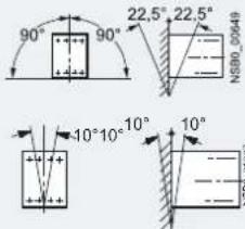 | -(fan integrated in the soft starter) | |||
| Permissible ambient temperatureOperationStorage | °C°C | -25...+60; (derating from +40)-40...+80 | |||
| Degree of protection | IP20 for 3RW40 2.;IP00 for 3RW40 3. and 3RW40 4. | IP00 | |||
13.2.14 3RW40 24, 26, 27, 28 power electronics
| Type | 3RW40283RW40273RW40263F | ||
| Power electronics | |||
| Current carrying capacity rated operating current I_e | |||
| •Acc. to IEC and UL/CSA1), for standalone assembly, AC-53a | |||
| -At 40°C | A | 3832.225.312.5 | |
| -At 50 °C | A | 34292311 | |
| -At 60 °C | A | 31262110 | |
| Minimum settable rated motor current I_M for motor overload protection | A | 2317105 | |
| Power loss | |||
| •During operation after startup of the motor at uninterrupted rated operat. curr.(40°C) approx. | W | 191382 | |
| •During starting at 300 % current limiting I_M (40°C) | W | 25622018868 | |
| Permissible rated motor current and starts per hour | |||
| •For normal starting (class 10): | |||
| -Rated motor curr. I_M^2) , ramp-up t. 3s | A | 38 / 3432 / 2925 / 2312.5 / 11 | |
| -Starts per hour3) | 1/h | 19 / 1923 / 2323 / 2350 / 50 | |
| -Rated motor curr. I_M^2) , ramp-up t. 4s | A | 38 / 34 32 / 2925 / 2312.5 / 11 | |
| -Starts per hour3) | 1/h | 12 / 12 16 / 1615 / 1536 / 36 | |
| •For heavy-duty starting (class 15) | |||
| -Rated motor curr. I_M^2) , ramp-up t. 4,5s | A | 34 / 3130 / 2723 / 2111 / 10 | |
| -Starts per hour3) | 1/h | 18 / 1818 / 1821 / 2149 / 49 | |
| -Rated motor curr. I_M^2) , ramp-up t. 6s | A | 34 / 3130 / 2723 / 2111 / 10 | |
| -Starts per hour3) | 1/h | 13 / 1313 / 1314 / 1436 / 36 | |
| •For heavy-duty starting (class 20) | |||
| -Rated motor curr. I_M^2) , ramp-up t. 6s | A | 31 / 2827 / 2421 / 1910 / 9 | |
| -Starts per hour3) | 1/h | 18 / 1820 / 2021 / 2147 / 47 | |
| -Rated motor curr. I_M^2) , ramp-up t. 8s | A | 31 / 2827 / 2421 / 1910 / 9 | |
| -Starts per hour3) | 1/h | 13 / 1314 / 1415 / 1534 / 34 | |
1) Measurement at 60°C in accordance with UL/CSA not required.
2) 300 % current limiting on soft starter I_M . Tamb = 40 °C / 50 °C.
3) For intermittent duty S4 with ON time 30%, T_amb=40^/50^ , vertical standalone assembly. The specified switching frequencies do not apply to automatic mode. Factors for permissible switching frequency with different mounting position, direct assembly, side-by-side assembly and installation of an optional additional fan, see Configuration chapter.
4) Maximum settable rated motor current I_M , depending on the CLASS setting.
13.2.15 3RW40 36, 37, 38, 46, 47 power electronics
| Type | 3RW40473RW40463RW40383R | ||
| Power electronics | |||
| Current carrying capacity rated operating current I_b | |||
| •Acc. to IEC and UL/CSA1), for standalone assembly, AC-53a | |||
| -At 40°C | A | 10680726345 | |
| -At 50 °C | A | 987362.15842 | |
| -At 60 °C | A | 9066605339 | |
| Minimum settable rated motor current I_M for motor overload protection | A | 4643352623 | |
| Power loss | |||
| •During operation after startup of the motor at uninterrupted rated operat. curr.(40°C) approx. | W | 211215126 | |
| •During starting at 300 % current limiting I_M (40°C) | W | 768576500444316 | |
| Permissible rated motor current and starts per hour | |||
| •For normal starting (class 10): | |||
| -Rated motor curr. I_M^2) , ramp-up t. 3s | A | 106 / 9880 / 7372 / 6263 / 5845 / | |
| -Starts per hour3) | 1/h | 15 / 1522 / 2222 / 2223 / 2338 / 3 | |
| -Rated motor curr. I_M^2) 4), ramp-up t. 4s | A | 106 / 9880 / 7372 / 6263 / 5845 / | |
| -Starts per hour3) | 1/h | 10 / 1015 / 1515 / 1515 / 1526 / 2 | |
| •For heavy-duty starting (class 15) | |||
| -Rated motor curr. I_M^2) , ramp-up t. 4.5s | A | 84 / 7770 / 6456 / 5250 / 4642 / 3 | |
| -Starts per hour3) | 1/h | 23 / 2324 / 2434 / 3434 / 3430 / 3 | |
| -Rated motor curr. I_M^2) 4), ramp-up t. 6s | A | 84 / 7770 / 6456 / 5250 / 4642 / 3 | |
| -Starts per hour3) | 1/h | 17 / 1716 / 1624 / 2424 / 2421 / 2 | |
| •For heavy-duty starting (class 20) | |||
| -Rated motor curr. I_M^2) , ramp-up t. 6s | A | 77 / 7064 / 5850 / 4646 / 4238 / 3 | |
| -Starts per hour3) | 1/h | 23 / 2323 / 2334 / 3431 / 3130 / 3 | |
| -Rated motor curr. I_M^2) 4), ramp-up t. 8s | A | 77 / 7064 / 5850 / 4646 / 4238 / 3 | |
| -Starts per hour3) | 1/h | 16 / 1616 / 1624 / 2422 / 2221 / 2 | |
1) Measurement at 60°C in accordance with UL/CSA not required.
2) 300 % current limiting on soft starter I_M . Tamb = 40 °C / 50 °C
3) For intermittent duty S4 with ON time 30%, T_amb = 40^ / 50^ , vertical standalone assembly. The specified switching frequencies do not apply to automatic mode. Factors for permissible switching frequency with different mounting position, direct assembly, side-by-side assembly and installation of an optional additional fan, see Configuration chapter.
4) Maximum settable rated motor current I_M , depending on the CLASS setting.
13.2.16 3RW40 55, 56, 73, 74, 75, 76 power electronics
| Type | 3RW40763RW40753RW4 | ||||
| Power electronics | |||||
| Current carrying capacity rated operating current I_e | |||||
| •Acc. to IEC and UL/CSA1), for standalone assembly, AC-53a | |||||
| -At 40°C | A | 432356280230162134 | |||
| -At 50 °C | A | 385315248205145117 | |||
| -At 60 °C | A | 335280215180125100 | |||
| Minimum settable rated motor current I_M for motor overload protection | A | 207131130808759 | |||
| Power loss | |||||
| •During operation after startup of the motor at uninterrupted rated operat. curr.(40°C) approx. | W | 7560 | 1651259075 | ||
| •During starting at 350%2)current limiting I_M (40°C) | W | 36003277325724481355* | |||
| Permissible rated motor current and starts per hour | |||||
| •For normal starting (class 10): | |||||
| -Rated motor curr. I_M^2) , ramp-up t. 10s | A | 134 / 117 | 162 / 145 | 432 / 385356 / 315280 / 2 | |
| -Starts per hour3) | 1/h | 17 / 1716 / 1620 / 2014 / * | |||
| -Rated motor curr. I_M^2) 4), ramp-up t. 20s | A | 432 / 385356 / 315280 / 2 | |||
| -Starts per hour3) | 1/h | 7 / 7 | 5 / 55 / 58 / 83 / 31.4 / 1.4 | ||
| •For heavy-duty starting (class 15) | |||||
| -Rated motor curr. I_M^2) , ramp-up t. 15s | A | 134 / 117 | 152 / 140 | 402 / 385341 / 315250 / 2 | |
| -Starts per hour3) | 1/h | 12 / 1211 / 1113 / 1311 / * | |||
| -Rated motor curr. I_M^2) 4), ramp-up t. 30s | A | 402 / 385341 / 315250 / 2 | |||
| -Starts per hour3) | 1/h | 2 / 22 / 26 / 61 / 11.7 / 1.7 | |||
| •For heavy-duty starting (class 20) | |||||
| -Rated motor curr. I_M^2) , ramp-up t. 20s | A | 372 / 340311 / 280230 / 2 | |||
| -Starts per hour3) | 1/h | 10 / 1010 / 1010 / 1010 / * | |||
| -Rated motor curr. I_M^2) 4), ramp-up t. 40s | A | 372 / 340311 / 280230 / 2 | |||
| -Starts per hour3) | 1/h | 2 / 2 | 1 / 11 / 15 / 51 / 12 / 2 | ||
1) Measurement at 60°C in accordance with UL/CSA not required.
2) 350% current limiting on soft starter I_M . Tamb = 40 °C / 50 °C
3) For intermittent duty S4 with ON time 70%, T_amb=40^ / 50^ , vertical standalone assembly. The specified switching frequencies do not apply to automatic mode.
4) Maximum settable rated motor current I_M , depending on the CLASS setting.
13.2.17 3RW40 2., 3., 4. main conductor cross-sections
| Soft starters | Type | 3RW404.3RW403.3RW402 | |||
| Conductor cross-sections | |||||
| Screw terminals | Main conductors | ||||
| Front clamping point connected | • Solid | mm^2 | 2 x (1.5...2.5);2 x (2.5...6) according to IEC 60947;max. 1 x 10 | 2 x (2.5...16)2 x (1.5...16) | |
 | • With end sleeve | mm^2 | 2 x (1.5...2.5);2 x (2.5...6) | 1 x (2.5...35)1 x (0.75...25) | |
| • Stranded | mm^2 | - | 1 x (4...70)1 x (0.75...35) | ||
| • AWG cables | |||||
| - Solid | AWG | 2 x (16 ... 12) | |||
| - Solid or stranded | AWG | 2 x (14...10) | 2 x (10...1/0)1 x (18...2) | ||
| - Stranded | AWG | 1 x 8 | - | - | |
| Rear clamping point connected | • Solid | mm^2 | - | 2 x (2.5...16)2 x (1.5...16) | |
| • With end sleeve | mm^2 | - | 1 x (2.5...50)1 x (1.5...25) | ||
| • Stranded | mm^2 | - | 1 x (10...70)1 x (1.5...35) | ||
| [28Y6] | • AWG cables | ||||
| - Solid or stranded | AWG | - | 1 x (16...2) | 2 x (10...1/0) | |
| Both clamping points connected | • Solid | mm^2 | - | 2 x (2.5...16)2 x (1.5...16) | |
| • With end sleeve | mm^2 | - | 2 x (2.5...35)2 x (1.5...16) | ||
| • Stranded | mm^2 | - | 2 x (10...50)2 x (1.5...25) | ||
 | • AWG cables | ||||
| - Solid or stranded | AWG | - | 1 x (10...2/0)2 x (16...2) | ||
| • Tightening torque | Nm | 2...2.5 | 6.54.5 | ||
| lb.in | 18...22 | 40 | 58 | ||
| Tools | PZ2 | Allen screw 4 mm PZ2 | |||
| Degree of protection | IP20 | IP20(terminal compartment IP00) | IP20(terminal compartment IP00) | ||
| Spring-loaded terminals | Main conductors | ||||
| • Solid | mm^2 | 1...10 | - | ||
| • Finely stranded with end sleeve | mm^2 | 1...6 end sleeves without plastic collar | - | ||
| • AWG cables | |||||
| - Solid or stranded (finely stranded) | AWG | 16...10 | - | ||
| - Stranded | AWG | 1 x 8 | - | ||
| Tools | DIN ISO 2380-1A0; 5 x 3 | - | |||
| Degree of protection | IP20 | - | |||
| Busbar connections | Main conductors | ||||
| • With cable lug according to DIN 46234 or 20 mm wide | |||||
| - Stranded | mm^2 | 2 x (10...70)- | |||
| - Finely-stranded | mm^2 | - | 2 x (10...50) | ||
| • AWG cables, solid or stranded | AWG | - | 2 x (7...1/0) | ||
13.2.18 3RW40 5., 7. main conductor cross-sections
| Soft starters | Type | 3RW405. | 3RW407. | |
| Conductor cross-sections | ||||
Screw terminalsWith box terminalFront clamping point connected | Main conductors: | 3RT19 55-4G (55 kW)16...70 | 3RT19 66-4G70...24095...300Min. 6 x 9 x 0.8,Max. 6 x 15.5 x 0.86...2/0 | |
| • Finely stranded with end sleeve | mm^2 | |||
| • Stranded | mm^2 | |||
| • Ribbon cable conductors (number x width x thickness) | mm | |||
| • AWG cables, solid or stranded | AWG | |||
Rear clamping point connected | • Finely stranded with end sleeve | mm^2 | 16...70 | 120...185 |
| • Stranded | mm^2 | 16...70 | 120...240 | |
| • Ribbon cable conductors (number x width x thickness) | mm | Min. 3 x 9 x 0.8,Max. 6 x 15.5 x 0.86...2/0 | Min. 6 x 9 x 0.8Max. 20 x 24 x 0.5250...500 kcmil | |
| • AWG cables, solid or stranded | AWG | |||
Both clamping points connected | • Finely stranded with end sleeve | mm^2 | Max. 1 x 50, 1 x 70 | Min. 2 x 50; max. 2 x 185 |
| • Stranded | mm^2 | Max. 2 x 70 | Max. 2 x 70; max. 2 x 240 | |
| • Ribbon cable conductors (number x width x thickness) | mm | Max. 2 x (6 x 15.5 x 0.8) | Max. 2 x (20 x 24 x 0.5) | |
| • AWG cables, solid or stranded | AWG | Max. 2 x 1/0 | Min. 2 x 2/0; max. 2 x 500 kcmil | |
| • Terminal screws-Tightening torque | Nm | M10 (hexagon socket, A/F4)10...12 | M12 (hexagon socket, A/F5)20...22 | |
| lb.in | 90...110 | 180...195 | ||
Screw terminalsWith box terminalFront or rear clamping point connected [NS300480] [NS300480] | Main conductors: | 3RT19 56-4G16...120 | ||
| • Finely stranded with end sleeve | mm^2 | |||
| • Stranded | mm^2 | 16...120 | ||
| • Ribbon cable conductors (number x width x thickness) | mm | Min. 3 x 9 x 0.8Max. 6 x 15.5 x 0.86...250 kcmil | ||
| • AWG cables, solid or stranded | AWG | |||
Both clamping points connected [TENAMPTED] [TENAMPTED] | • Finely stranded with end sleeve | mm^2 | Max. 1 x 95, 1 x 120 | |
| • Stranded | mm^2 | Max. 2 x 120 | ||
| • Ribbon cable conductors (number x width x thickness) | mm | Max. 2 x (10 x 15.5 x 0.8) | ||
| • AWG cables, solid or stranded | AWG | Max. 2 x 3/0 | ||
| Screw terminals | Main conductors:Without box terminal / busbar connection | |||
| • Finely stranded with cable lug | mm^2 | 16...95 ^1) | 50...240 ^2) | |
| • Stranded with cable lug | mm^2 | 25...120 ^1) | 70...240 ^2) | |
| • AWG cables, solid or stranded | AWG | 4...250 kcmil | 2/0...500 kcmil | |
| • Connecting bar (max. width) | mm | 17 | 25 | |
| • Terminal screws-Tightening torque | Nm | M8x25 (A/F13)10...14 | M10x30 (A/F17)14...24 | |
| lb.in | 89...124 | 124...210 | ||
1) When connecting cable lugs to DIN 46235, use 3RT19 56-4EA1 terminal cover for conductor cross-sections from 95 mm ^2 to ensure the required clearance between phases.
2) When connecting cable lugs to DIN 46234 or DIN 46235, use 3RT19 66-4EA1 terminal cover for conductor cross-sections from 240 mm² or 185 mm² respectively to ensure the required clearance between phases.
13.2.19 3RW40 .. auxiliary conductor cross-sections
| TypeSoft starters | 3RW40.. | |
| Conductor cross-sections | ||
| Auxiliary conductors (1 or 2 conductors can be connected) | ||
| Screw terminals | ||
| • Solid | mm^2 | 2 x (0.5...2.5) |
| • Finely stranded with end sleeve | mm^2 | 2 x (0.5...1.5) |
| • AWG cables | ||
| - Solid or stranded | AWG | 2 x (20...14) |
| - Finely stranded with end sleeve | AWG | 2 x (20...16) |
| • Terminal screws | ||
| - Tightening torque | Nm | 0.8...1.2 |
| lb.in | 7...10.3 | |
| Spring-loaded terminals | ||
| • Solid | ||
| - 3RW40 2. to 3RW40 4. | mm^2 | 2 x (0.25...2.5) |
| - 3RW40 5., 3RW40 7. | mm^2 | 2 x (0.25...1.5) |
| • Finely stranded with end sleeve | mm^2 | 2 x (0.25...1.5) |
| • AWG cables, solid or stranded | AWG | 2 x (24...14) for 3RW402....3RW404.;2 x (24...16) for 3RW405. and 3RW407. |
13.2.20 Electromagnetic compatibility according to EN 60947-4-2
| ParametersStandard | ||
| Electromagnetic compatibility according to EN 60947-4-2 | ||
| EMC interference immunity | ||
| Electrostatic discharge (ESD) | EN 61000-4-2 | ±4 kV contact discharge, ±8 kV air discharge |
| Electromagnetic RF fields | EN 61000-4-3 | Frequency range: 80 to 1000 MHz with 80% at 1 kHzDegree of severity 3: 10 V/m |
| Conducted RF interference | EN 61000-4-6 | Frequency range: 150 kHz...80 MHz with 80% at 1 kHzInterference 10 V |
| RF voltages and RF currents on cables | ||
| • Burst | EN 61000-4-4 | ±2 kV / 5 kHz |
| • Surge | EN 61000-4-5 | ±1 kV line to line±2 kV line to ground |
| EMC interference emission | ||
| EMC interference field strength | EN 55011 | Limit value of Class A at 30...1000 MHz,Limit value of Class B for 3RW402.; 24 V AC/DC |
| Radio interference voltage | EN 55011 | Limit value of Class A at 0.15...30 MHz,Limit value of Class B for 3RW402.; 24 V AC/DC |
| Radio interference suppression filters | ||
| Degree of noise suppression A (industrial applications) | Not required | |
| Degree of noise suppression B (applications for residential areas) | ||
| Control voltage | ||
| • 110...230 V AC/DC | Not available ^1) | |
| • 115/230 V AC | Not available ^1) | |
| • 24 V AC/DC | Not required for 3RW402.;Required for 3RW403. and 3RW404. (see table) | |
1) Degree of noise suppression B cannot be obtained through the use of filters as the strength of the electromagnetic field is not attenuated by the filter.
13.2.21 Recommended filters
| Soft starter types | Nominal current Soft starters | Recommended filters ^1) | ||
| Voltage range 200 to 480 V | ||||
| Filter types | A | TerminalsNominal current filters mm^2 | ||
| A | ||||
| 3RW40 36 | 4EF1512-1AA1045 | 1650 | ||
| 3RW40 37 | 4EF1512-2AA1063 | 2566 | ||
| 3RW40 38 | 4EF1512-3AA1072 | 2590 | ||
| 3RW40 46 | 80 | 4EF1512-3AA10 | 2590 | |
| 3RW40 47 | 106 | 4EF1512-4AA10 | 50120 | |
1) The radio interference suppression filter is used to remove the conducted
interference from the main circuit. The field-related emissions comply
with degree of noise suppression B. The filter should be selected under standard conditions:
10 starts per hour, ramp-up time 4 s at 300% I _e
13.2.22 Types of coordination
Types of coordination
The type of coordination according to which the motor feeder with soft starter is mounted depends on the application-specific requirements. Normally, fuseless mounting (combination of motor starter protector and soft starter) is sufficient. If type of coordination 2 needs to be fulfilled, semiconductor fuses must be fitted in the motor feeder.
ToC 1 Type of coordination 1 in accordance with IEC 60947-4-1:
The device is defective following a short-circuit failure and therefore unsuitable for further use (personnel and equipment must not be put at risk).
Type of coordination 2 in accordance with IEC 60947-4-1:
The device is suitable for further use following a short-circuit failure (personnel and equipment must not be put at risk).
The type of coordination only refers to soft starters in conjunction with the stipulated protective device (motor starter protector / fuse), not to additional components in the feeder.
13.2.23 Fuseless version
| Fuseless version | |||||||||
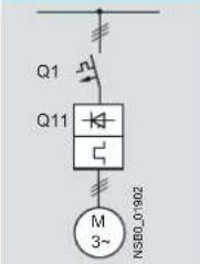 | |||||||||
| Soft startersQ11Type A | Nominal current | Motor starter protectors ^1) | |||||||
| Q1Type | Q1Type kA A | Iq max | Rated current | 575 V +10%400 V +10%400 Current | Rated 0% current | ||||
| Type of coordination 1^2) | |||||||||
| 3RW40 24 | 12.5 | 3RV1 021-1KA10 | 3RV20 21-4AA/3RV20 11-4AA(in size S00) | 3RV1 321-1KC10 | 3RV23 21-4AC/3RV23 11-4AC(in size S00) | 55 | 16 | - | - |
| 3RW40 26 | 25 | 3RV1 021-4DA10 | 3RV20 21-4DA | 3RV1 321-4DC10 | 3RV23 21-4DC | 55 | 25 | - | - |
| 3RW40 27 | 32 | 3RV1 031-4EA10 | 3RV20 21-4EA | 3RV1 331-4EC10 | 3RV23 21-4EC | 55 | 32 | - | - |
| 3RW40 28 | 38 | 3RV1 031-4FA10 | 3RV20 21-4FA | 3RV1 331-4FC10 | 3RV23 21-4FC | 55 | 40 | - | - |
| 3RW40 36 | 45 | 3RV1 031-4GA10 | 3RV1 331-4GC10 | 20 | 45 | - | - | ||
| 3RW40 37 | 63 | 3RV1 041-4JA10 | 3RV1 341-4JC10 | 20 | 63 | - | - | ||
| 3RW40 38 | 72 | 3RV1 041-4KA10 | 3RV1 341-4KC10 | 20 | 75 | - | - | ||
| 3RW40 46 | 80 | 3RV1 041-4LA10 | 3RV1 341-4LC10 | 11 | 90 | - | - | ||
| 3RW40 47 | 106 | 3RV1 041-4MA10 | 3RV1 341-4MC10 | 11 | 100 | - | - | ||
| 3RW40 55 | 134 | 3VL3 720-2DC36 | 35 | 200 | 3VL3 720-1DC36 | 12 | |||
| 3RW40 56 | 162 | 3VL3 720-2DC36 | 35 | 200 | 3VL3 720-1DC36 | 12 | |||
| 3RW40 73 | 230 | 3VL4 731-2DC36 | 65 | 315 | 3VL5 731-3DC36 | 35 | |||
| 3RW40 74 | 280 | 3VL4 731-2DC36 | 65 | 315 | 3VL5 731-3DC36 | 35 | |||
| 3RW40 75 | 356 | 3VL4 740-2DC36 | 65 | 400 | 3VL5 740-3DC36 | 35 | |||
| 3RW40 76 | 432 | 3VL5 750-2DC36 | 65 | 500 | 3VL5 750-3DC36 | 35 | |||
1) The rated motor current must be considered when selecting the devices. The 3RV13 and 3RV23 motor starter protectors are used for starter combinations (without motor protection). In this case, motor protection is provided by the 3RW40 soft starter.
2) The types of coordination are described in chapter Types of coordination [Page 155].
13.2.24 Fused version (line protection only)
| Fused version (line protection only) | ||||||
| F1 Q21 Q11 M 3- | ||||||
| Type | Nominal current | Type | Rated current=Size | Line contactors Line protection, maximumSoft starters (optional) | ||
| A | A | Q21F1Q11 | ||||
| Type of coordination 1): Lq = 65 kA at 600 V + 5% | ||||||
| 3RW40 24 | 12.5 | 3NA3 820-6 | 50 | 00 | 3RT10 24 | 3RT20 25/3RT20 18 (in size S00) |
| 3RW40 26 | 25 | 3NA3 822-6 | 63 | 00 | 3RT10 26 | 3RT20 26 |
| 3RW40 27 | 32 | 3NA3 824-6 | 80 | 00 | 3RT10 34 | 3RT20 27 |
| 3RW40 28 | 38 | 3NA3 824-6 | 80 | 00 | 3RT10 35 | 3RT20 28 |
| 3RW40 36 | 45 | 3NA3 130-6 | 100 | 1 | 3RT10 36 | |
| 3RW40 37 | 63 | 3NA3 132-6 | 125 | 1 | 3RT10 44 | |
| 3RW40 38 | 72 | 3NA3 132-6 | 125 | 1 | 3RT10 45 | |
| 3RW40 46 | 80 | 3NA3 136-6 | 160 | 1 | 3RT10 45 | |
| 3RW40 47 | 106 | 3NA3 136-6 | 160 | 1 | 3RT10 46 | |
| 3RW40 55 | 134 | 3NA3 244-6 | 250 | 2 | 3RT10 55-6A.36 | |
| 3RW40 56 | 162 | 3NA3 244-6 | 250 | 2 | 3RT10 56-6A.36 | |
| 3RW40 73 | 230 | 2 x 3NA3 354-6 | 2 x 355 | 3 | 3RT10 65-6A.36 | |
| 3RW40 74 | 280 | 2 x 3NA3 354-6 | 2 x 355 | 3 | 3RT10 66-6A.36 | |
| 3RW40 75 | 356 | 2 x 3NA3 365-6 | 2 x 500 | 3 | 3RT10 75-6A.36 | |
| 3RW40 76 | 432 | 2 x 3NA3 365-6 | 2 x 500 | 3 | 3RT10 76-6A.36 | |
1) The types of coordination are described in chapter Types of coordination [Page 155]. Type of coordination 1 only refers to soft starters in conjunction with the stipulated protective device (motor starter protector / fuse), not to additional components in the feeder.
13.2.25 Fused version with SITOR 3NE1 fuses
Assembly as for type of coordination 2, with SITOR all-range fuses (F'1) for combined thyristor and line protection.
| Fused version with SITOR 3NE1 fuses (semiconductor and line protection) | ||||||
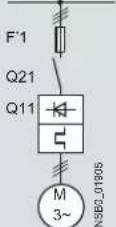 | For suitable fuse bases, refer to "SENTRON switching and protecting devices for power distribution" → "Switch disconnectors" the LV1 Catalog and to "BETA protecting" → "SITOR semiconductor fuses" in the ET B1 Catalog or consult www.siemens.de/sitor | |||||
| Nominal current | All-range fusesSoft starters | Line contactors (optional) | ||||
| F'1Q11 | Rated current=Size | Q21 | ||||
| ATypeAType | ||||||
| Type of coordination 2^1) : I_q = 65 kA at 600 V + 5% | ||||||
| 3RW40 24 | 12.5 | 3NE1 814-0 | 20 | 000 | 3RT10 24 | 3RT20 25 |
| 3RW40 26 | 25 | 3NE1 803-0 | 35 | 000 | 3RT10 26 | 3RT20 26 |
| 3RW40 27 | 32 | 3NE1 020-2 | 80 | 00 | 3RT10 34 | 3RT20 27 |
| 3RW40 28 | 38 | 3NE1 020-2 | 80 | 00 | 3RT10 35 | 3RT20 28 |
| 3RW40 36 | 45 | 3NE1 020-2 | 80 | 00 | 3RT10 36 | |
| 3RW40 37 | 63 | 3NE1 820-0 | 80 | 000 | 3RT10 44 | |
| 3RW40 38 | 72 | 3NE1 820-0 | 80 | 000 | 3RT10 45 | |
| 3RW40 46 | 80 | 3NE1 021-0 | 100 | 00 | 3RT10 45 | |
| 3RW40 47 | 106 | 3NE1 022-0 | 125 | 00 | 3RT10 46 | |
| 3RW40 55 | 134 | 3NE1 227-2 | 250 | 1 | 3RT10 55-6A.36 | |
| 3RW40 56 | 162 | 3NE1 227-2 | 250 | 1 | 3RT10 56-6A.36 | |
| 3RW40 73 | 230 | 3NE1 331-2 | 350 | 2 | 3RT10 65-6A.36 | |
| 3RW40 74 | 280 | 3NE1 333-2 | 450 | 2 | 3RT10 66-6A.36 | |
| 3RW40 75 | 356 | 3NE1 334-2 | 500 | 2 | 3RT10 75-6A.36 | |
| 3RW40 76 | 432 | 3NE1 435-2 | 560 | 3 | 3RT10 76-6A.36 | |
| Nominal current | All-range fusesSoft starters | Line contactors (optional) | ||||
| F'1Q11 | Rated current=Size | |||||
| ATypeAType | Q21 | |||||
| Type of coordination 2 ^1) : I_q = 65kA at 600 V + 5% | ||||||
| 3RW40 24 | 12.5 | 3NE1 814-0 | 20 | 000 | 3RT10 24 | 3RT20 25 |
| 3RW40 26 | 25 | 3NE1 803-0 | 35 | 000 | 3RT10 26 | 3RT20 26 |
| 3RW40 27 | 32 | 3NE1 020-2 | 80 | 00 | 3RT10 34 | 3RT20 27 |
| 3RW40 28 | 38 | 3NE1 020-2 | 80 | 00 | 3RT10 35 | 3RT20 28 |
| 3RW40 36 | 45 | 3NE1 020-2 | 80 | 00 | 3RT10 36 | |
| 3RW40 37 | 63 | 3NE1 820-0 | 80 | 000 | 3RT10 44 | |
| 3RW40 38 | 72 | 3NE1 820-0 | 80 | 000 | 3RT10 45 | |
| 3RW40 46 | 80 | 3NE1 021-0 | 100 | 00 | 3RT10 45 | |
| 3RW40 47 | 106 | 3NE1 022-0 | 125 | 00 | 3RT10 46 | |
| 3RW40 55 | 134 | 3NE1 227-2 | 250 | 1 | 3RT10 55-6A.36 | |
| 3RW40 56 | 162 | 3NE1 227-2 | 250 | 1 | 3RT10 56-6A.36 | |
| 3RW40 73 | 230 | 3NE1 331-2 | 350 | 2 | 3RT10 65-6A.36 | |
| 3RW40 74 | 280 | 3NE1 333-2 | 450 | 2 | 3RT10 66-6A.36 | |
| 3RW40 75 | 356 | 3NE1 334-2 | 500 | 2 | 3RT10 75-6A.36 | |
| 3RW40 76 | 432 | 3NE1 435-2 | 560 | 3 | 3RT10 76-6A.36 | |
1) The types of coordination are described in chapter Types of coordination [Page 155]. Type of coordination 2 only refers to soft starters in conjunction with the stipulated protective device (motor starter protector / fuse), not to additional components in the feeder.
13.2.26 Fused version with SITOR 3NE3/4/8 fuses
Assembly as for type of coordination 2, with additional SITOR fuses (F3) for thyristor protection only.
| Fused version with 3NE3 SITOR fuses (semiconductor protection by fuse, line, and overload protection by motor starter protector; alternatively, installation with contactor and overload relay possible) | |||||||||||
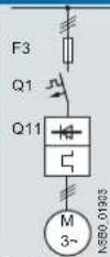 | 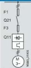 | For suitable fuse bases, refer to under "SENTRON switching and protecting devices for power distribution" → "Switch disconnectors" in the LV1 Catalog and to "BETA protecting" → "SITOR semiconductor fuses" in the ET B1 Catalog or consult www.siemens.de/sitor | |||||||||
| Soft startersQ11Type | Nominal currentA | Semiconductor fuses, minimum | Semiconductor fuses, maximum | Semiconductor fuses, minimum | |||||||
| F3Type | Rated currentA | Size | F3Type | Rated currentA | Size | F3Type | Rated currentA | Size | |||
| Type of coordination 2^1) : I_q = 65kA at 600V + 5% | |||||||||||
| 3RW40 24 | 12.5 | - | - | - | - | - | - | 3NE4101 | 32 | 0 | |
| 3RW40 26 | 25 | - | - | - | 3NE3 221 | 100 | 1 | 3NE4102 | 40 | 0 | |
| 3RW40 27 | 32 | - | - | - | 3NE3 224 | 160 | 1 | 3NE4118 | 63 | 0 | |
| 3RW40 28 | 38 | - | - | - | 3NE3 224 | 160 | 1 | 3NE4118 | 63 | 0 | |
| 3RW40 36 | 45 | - | - | - | 3NE3 224 | 160 | 1 | 3NE4120 | 80 | 0 | |
| 3RW40 37 | 63 | - | - | - | 3NE3 225 | 200 | 1 | 3NE4121 | 100 | 0 | |
| 3RW40 38 | 72 | 3NE3 221 | 100 | 1 | 3NE3 227 | 250 | 1 | - | - | - | |
| 3RW40 46 | 80 | 3NE3 222 | 125 | 1 | 3NE3 225 | 200 | 1 | - | - | - | |
| 3RW40 47 | 106 | 3NE3 224 | 160 | 1 | 3NE3 231 | 350 | 1 | - | - | - | |
| 3RW40 55 | 134 | 3NE3 227 | 250 | 1 | 3NE3 335 | 560 | 2 | - | - | - | |
| 3RW40 56 | 162 | 3NE3 227 | 250 | 1 | 3NE3 335 | 560 | 2 | - | - | - | |
| 3RW40 73 | 230 | 3NE3 232-0B | 400 | 1 | 3NE3 333 | 450 | 2 | - | - | - | |
| 3RW40 74 | 280 | 3NE3 233 | 450 | 1 | 3NE3 336 | 630 | 2 | - | - | - | |
| 3RW40 75 | 356 | 3NE3 335 | 560 | 2 | 3NE3 336 | 630 | 2 | - | - | - | |
| 3RW40 76 | 432 | 3NE3 337-8 | 710 | 2 | 3NE3 340-8 | 900 | 2 | - | - | - | |
| Soft startersQ11Type | Nominal currentA | Semiconductor fuses, max. | Semiconductor fuses, min. | Semiconductor fuses, max. | Cylindrical fuses | ||||||
| F3Type | Rated currentA | Size | F3Type | Rated currentA | Size | F3Type | Rated currentA | Size | Rated currentA | ||
| Type of coordination 2^1) : I_q = 65kA at 600V + 5% | |||||||||||
| 3RW40 24 | 12.5 | 3NE4117 | 50 | 0 | 3NE8015-1 | 25 | 00 | 3NE8017-1 | 50 | 00 | 3NC2240 40 |
| 3RW40 26 | 25 | 3NE4117 | 50 | 0 | 3NE8017-1 | 50 | 00 | 3NE8021-1 | 100 | 00 | 3NC2263 63 |
| 3RW40 27 | 32 | 3NE4118 | 63 | 0 | 3NE8018-1 | 63 | 00 | 3NE8022-1 | 125 | 00 | 3NC2280 80 |
| 3RW40 28 | 38 | 3NE4118 | 63 | 0 | 3NE8020-1 | 80 | 00 | 3NE8024-1 | 160 | 00 | 3NC2280 80 |
| 3RW40 36 | 45 | 3NE4120 | 80 | 0 | 3NE8020-1 | 80 | 00 | 3NE8024-1 | 160 | 00 | 3NC2280 80 |
| 3RW40 37 | 63 | 3NE4121 | 100 | 0 | 3NE8021-1 | 100 | 00 | 3NE8024-1 | 160 | 00 | - |
| 3RW40 38 | 72 | - | - | - | 3NE8022-1 | 125 | 00 | 3NE8024-1 | 160 | 00 | - |
| 3RW40 46 | 80 | - | - | - | 3NE8 022-1 | 125 | 00 | 3NE8024-1 | 160 | 00 | - |
| 3RW40 47 | 106 | - | - | - | 3NE8 024-1 | 160 | 00 | 3NE8024-1 | 160 | 00 | - |
| 3RW40 55 | 134 | - | - | - | - | - | - | - | - | - | - |
| 3RW40 56 | 162 | - | - | - | - | - | - | - | - | - | - |
| 3RW40 73 | 230 | - | - | - | - | - | - | - | - | - | - |
| 3RW40 74 | 280 | - | - | - | - | - | - | - | - | - | - |
| 3RW40 75 | 356 | - | - | - | - | - | - | - | - | - | - |
| 3RW40 76 | 432 | - | - | - | - | - | - | - | - | - | - |
13.2 3RW40
| Soft starters _1c Q11 | Nominalcurrent | Line contactors(optional)Q21 | Motor starter protectors400 V +10%Q1 | Ratedcurrent | 575 V +10%Q1 | Ratedcurrent | Line protection, maximumF1 | RatedcurrentATypeATypeATypeAType | |||
| Type of coordination 2^1) : I_q = 65 kA at 600 V + 5% | |||||||||||
| 3RW40 24 | 12.5 | 3RT10 24 | 3RT20 25/3RT20 18(in size S00) | 3RV1 021-4KA10 | 3RV20 21-4AA/3RV20 11-4AA(in size S00) | 16 | - | - | 3NA3 820-6 | 50 | 00 |
| 3RW40 26 | 25 | 3RT10 26 | 3RT20 26 | 3RV1 021-4DA10 | 3RV20 21-4DA | 25 | - | - | 3NA3 822-6 | 63 | 00 |
| 3RW40 27 | 32 | 3RT10 34 | 3RT20 27 | 3RV1 031-4EA10 | 3RV20 21-4EA | 32 | - | - | 3NA3 824-6 | 80 | 00 |
| 3RW40 28 | 38 | 3RT10 35 | 3RT20 28 | 3RV1 031-4FA10 | 3RV20 21-4FA | 40 | - | - | 3NA3 824-6 | 80 | 00 |
| 3RW40 36 | 45 | 3RT10 36 | 3RV1 031-4GA10 | 45 | - | - | 3NA3 130-6 | 100 | 1 | ||
| 3RW40 37 | 63 | 3RT10 44 | 3RV1 041-4JA10 | 63 | - | - | 3NA3 132-6 | 125 | 1 | ||
| 3RW40 38 | 72 | 3RT10 45 | 3RV1 041-4KA10 | 75 | - | - | 3NA3 132-6 | 125 | 1 | ||
| 3RW40 46 | 80 | 3RT10 45 | 3RV1 041-4LA10 | 90 | - | - | 3NA3 136-6 | 160 | 1 | ||
| 3RW40 47 | 106 | 3RT10 46 | 3RV1 041-4MA10 | 100 | - | - | 3NA3 136-6 | 160 | 1 | ||
| 3RW40 55 | 134 | 3RT10 55-6A.36 | 3VL3 720 | 2003VL3 | 32030244-6 | 250 | 2 | ||||
| 3RW40 56 | 162 | 3RT10 56-6A.36 | 3VL3 720 | 200 | 3VL3 720 | 200 | 3NA3 244-6 | 250 | 2 | ||
| 3RW40 73 | 230 | 3RT10 65-6A.36 | 3VL4 731 | 315 | 3VL5 731 | 315 | 2 x 3NA3 354-6 | 32 x 355 | |||
| 3RW40 74 | 280 | 3RT10 66-6A.36 | 3VL4 731 | 315 | 3VL5 731 | 315 | 2 x 3NA3 354-6 | 32 x 355 | |||
| 3RW40 75 | 356 | 3RT10 75-6A.36 | 3VL4 740 | 4003VL5 | 24030244-6 | 32 x 500 | |||||
| 3RW40 76 | 432 | 3RT10 76-6A.36 | 3VL5 750 | 500 | 3VL5 750 | 500 | 2 x 3NA3 365-6 | 32 x 500 | |||
1) The types of coordination are described in chapter Types of coordination [Page 155]. Type of coordination 2 only refers to soft starters in conjunction with the stipulated protective device (motor starter protector / fuse), not to additional components in the feeder.
13.2.27 Motor protection tripping characteristics for 3RW40 (with symmetry)
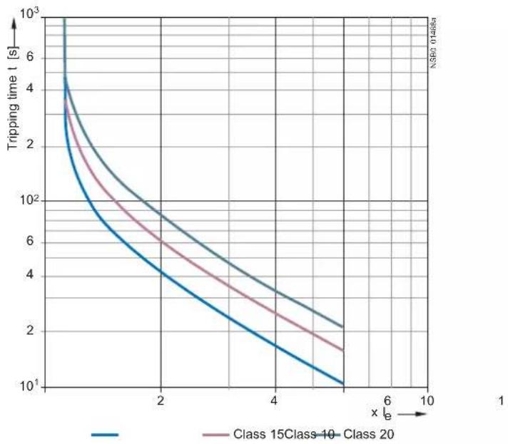
line
| x | Tripping time t [s] (Class 15Class-10) | Tripping time t [s] (Class 20) | | --- | --- | --- | | 0 | 1000 | 1000 | | 2 | 4 | 6 | | 4 | 2 | 3 | | 6 | 1 | 2 | | 10 | 1 | 1.5 |13.2.28 Motor protection tripping characteristics for 3RW40 (with asymmetry)
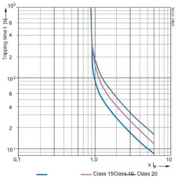
line
| x | Tripping time t [s] (Class 15Class 10) | Tripping time t [s] (Class 20) | | --- | --- | --- | | 0.1 | ~1000 | ~1000 | | 1.0 | ~30 | ~30 | | 10.0 | ~10 | ~15 |13.3 Win-Soft Starter selection and simulation software
13.3 Win-Soft Starter selection and simulation software
This software can be used to simulate and select all SIEMENS soft starters, taking into account various parameters such as the supply system conditions, motor data, load data, specific application requirements, etc.
It is a useful tool, which does away with the need for time-consuming and complex manual calculations if you need to select the optimum soft starter for your particular case.
The Win-Soft Starter selection and simulation software can be downloaded from (http://www.automation.siemens.com/mcms/low-voltage/en/industrial-controls/controls/solid-state-switching-devices/soft/software/Pages/default.aspx)
More information about soft starters can likewise be found on the Internet at (http://www.siemens.com/softstarter)
14.1 3RW30 for standard applications
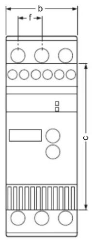
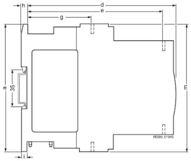
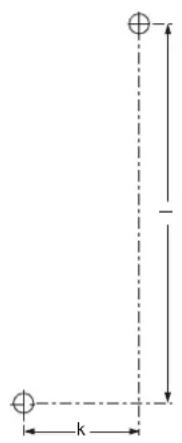
| Type / dimensions (mm) | mlkihgfedcba | |||||||||||
| 3RW301.-1. | 95 | 45 | 62 | 146 | 126 | 14.4 | 63 | 5 | 6.5 | 35 | 85 | 95 |
| 3RW301.-2. | 95 | 45 | 62 | 146 | 126 | 14.4 | 63 | 5 | 6.5 | 35 | 85 | 117.2 |
| 3RW302.-1. | 125 | 45 | 92 | 146 | 126 | 14.4 | 63 | 5 | 6.5 | 35 | 115 | 125 |
| 3RW302.-2. | 125 | 45 | 92 | 146 | 126 | 14.4 | 63 | 5 | 6.5 | 35 | 115 | 150 |
| 3RW303. | 160 | 55 | 110 | 163 | 140 | 18 | 63 | 5 | 6.5 | 30 | 150 | 144 |
| 3RW304. | 170 | 70 | 110 | 181 | 158 | 22.5 | 85 | 5 | 10 | 60 | 160 | 160 |
| Distances from grounded parts (mm) | Lateral | Top | Bottom | Fixing screws | Tightening torques (Nm) |
| 3RW301. | 5 | 60 | 40 | M4 | 1 |
| 3RW302. | 5 | 60 | 40 | M4 | 1 |
| 3RW303. | 30 | 60 | 40 | M4 | 1 |
| 3RW304. | 30 | 60 | 40 | M4 | 2 |
14.2 3RW40 for standard applications
14.2 3RW40 for standard applications
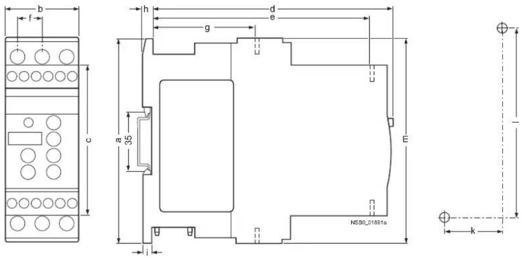
| Type / dimensions (mm) | a | b | c | d | e | f | g | h | i | k | l | m |
| 45 | 92 | 149 | 126 | 14.4 | 63 | 5 | 6.5 | 35 | 115 | 1251253RW402.-1. | ||
| 45 | 92 | 149 | 126 | 14.4 | 63 | 5 | 6.5 | 35 | 115 | 1501253RW402.-2. | ||
| 55 | 110 | 165 | 140 | 18 | 63 | 5 | 6.5 | 30 | 150 | 1441603RW403. | ||
| 70 | 110 | 183 | 158 | 22.5 | 85 | 5 | 10 | 60 | 160 | 1601703RW404. |
| Distances from grounded parts (mm) | Lateral | Top | Bottom | Fixing screws | Tightening torques (Nm) |
| 60 | 40 | M4 153RW402. | |||
| 60 | 40 | M4 1303RW403. | |||
| 60 | 40 | M4 2303RW404. |
14.2 3RW40 for standard applications
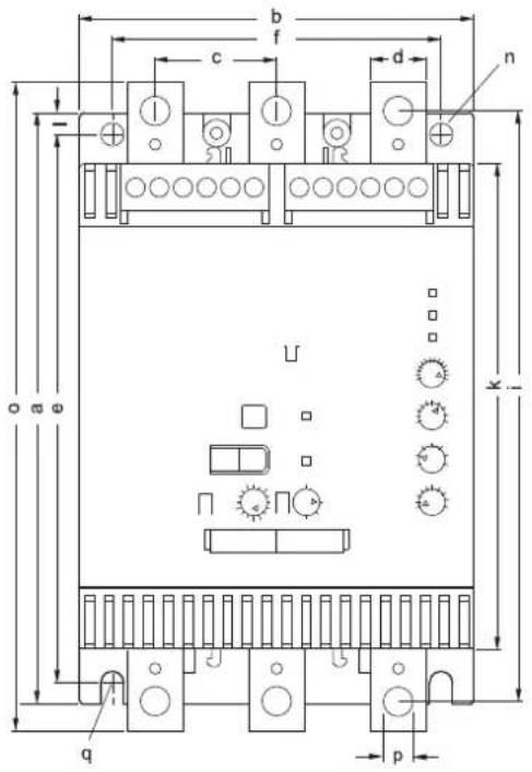
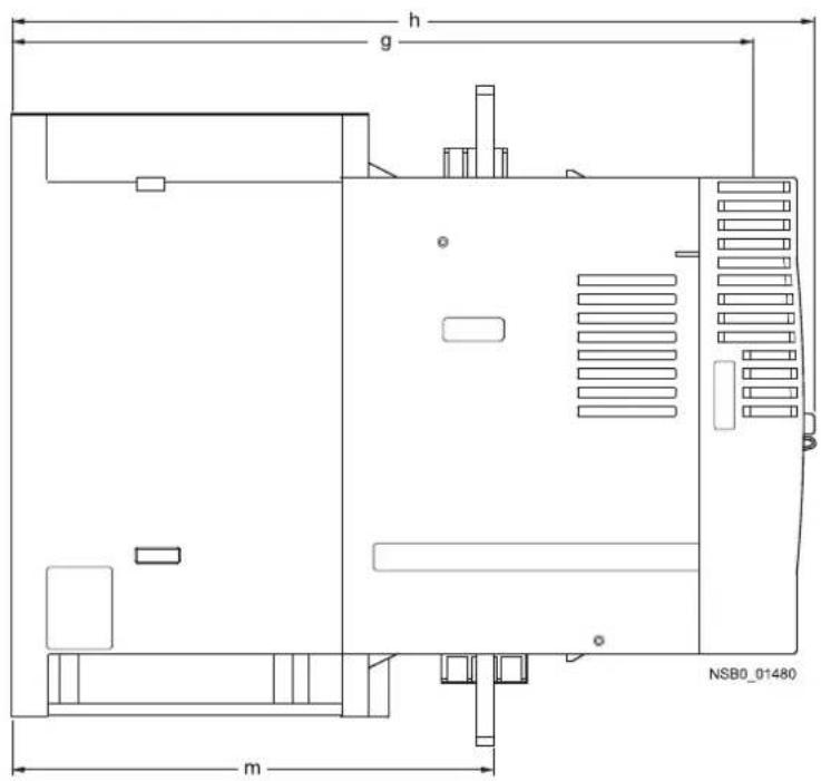
| qponmlkihgfedcbaType / dir | ||||||||||||||||
| 3RW405. | 180 | 120 | 37 | 17 | 167 | 100 | 223 | 250 | 180 | 148 | 6.5 | 153 | 7 | 198 | 9 | M6, 10 Nm |
| 3RW407. | 210 | 160 | 48 | 25 | 190 | 140 | 240 | 278 | 205 | 166 | 10 | 166 | 9 | 230 | 11 | M8, 15 Nm |
15.1 Typical circuit for the optional thermistor motor protection evaluation
A thermistor motor protection evaluation function is optionally available for the 24 V AC/DC control voltage version of the 3RW40 2 to 3RW40 4.
Note
If a thermistor is connected (PTC type A or Klixon), you must remove the copper jumper between terminals T11/21 and T22.
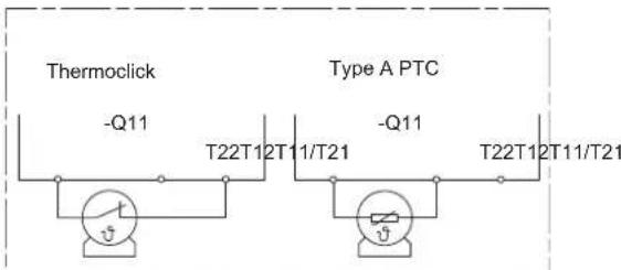
Figure 15-1 Optional thermistor motor protection evaluation
15.2 Control by pushbutton
15.2.1 Control of the 3RW30 by pushbutton
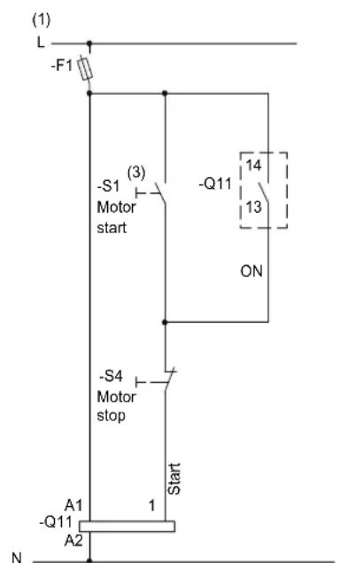
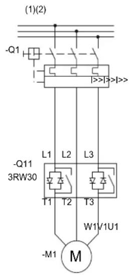
Figure 15-2 Wiring of the 3RW30 control and main circuits
(1) For the permissible values for the main and control voltage (dependent on the MLFB), refer to chapter Technical data [Page 121].
(2) Alternatively, the motor feeder can be assembled as a fuseless or fused version with type of coordination 1 or 2. For the assignment of fuses and switching devices, refer to chapter Technical data [Page 121]

WARNING
(3) Automatic restart. Can result in death, serious injury, or property damage.
Faults caused by incorrect control voltage, a missing load, or a phase failure (refer to chapter 3RW30: LEDs and troubleshooting [Page 44]) are automatically reset when the system returns to normal. An automatic restart is initiated and the 3RW restarted if a start command is present at the input.
If you do not want the motor to start automatically, you must integrate suitable additional components, e.g. phase failure or load monitoring devices, into the control and main circuits.
15.2.2 Control of the 3RW40 by pushbutton
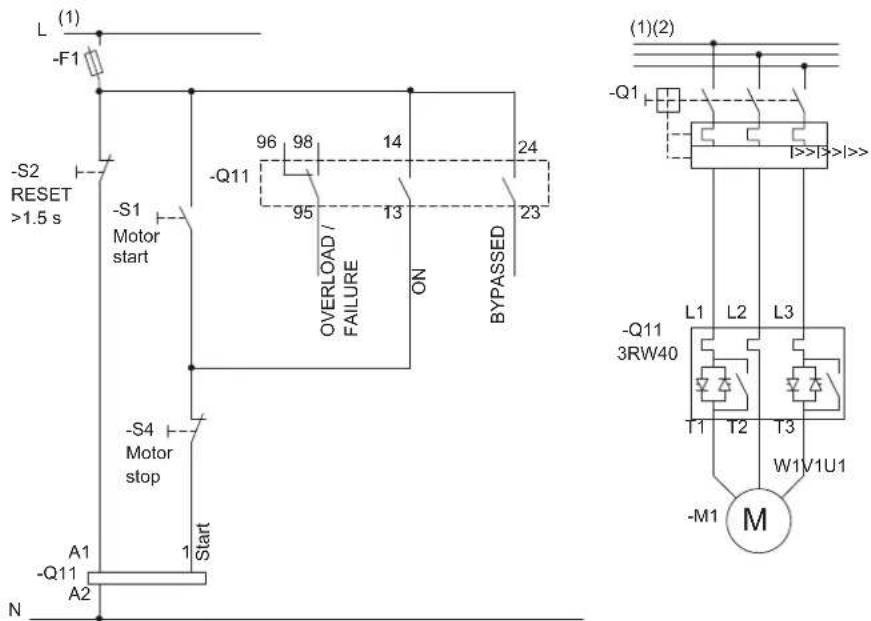
Figure 15-3 Wiring of the 3RW40 2 to 3RW40 4 control circuit and the 3RW40 2 to 3RW40 7 main circuit
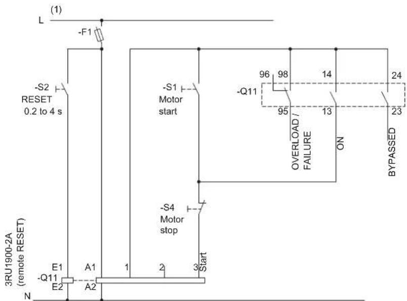
flowchart
graph TD
    L["Line L"] -->|F1| RESET["RESET 0.2 to 4 s"]
    RESET -->|S2| S2
    S2 -->|S1 Motor start| MotorStart["Motor stop"]
    MotorStart -->|S4 Motor stop| Overload["Overload / FAILURE ON"]
    Overload -->|Q11| Overload
    Overload -->|96| Overload
    Overload -->|98| Overload
    Overload -->|14| Overload
    Overload -->|24| Bypassed["Bypassed"]
    E1["E1"] --> A1["A1"]
    Q11["-Q11"] --> A2["A2"]
    N["N"] --> A2
    A1 --> Start["Start"]
    A2 --> Start
    style S2 fill:#f9f,stroke:#333
    style Q11 fill:#ccf,stroke:#333
    style Overload fill:#cfc,stroke:#333
Figure 15-4 Wiring of the 3RW40 5 to 3RW40 7 control circuit
(1) For the permissible values for the main and control voltage (dependent on the MLFB), refer to chapter Technical data [Page 121].
(2) Alternatively, the motor feeder can be assembled as a fuseless or fused version with type of coordination 1 or 2. For the assignment of fuses and switching devices, refer to chapter Technical data [Page 121]
For the optional thermistor motor protection evaluation, refer to typical circuit for the optional thermistor motor protection evaluation [Page 167].
15.3 Control by switch
15.3.1 Control of the 3RW30 by switch
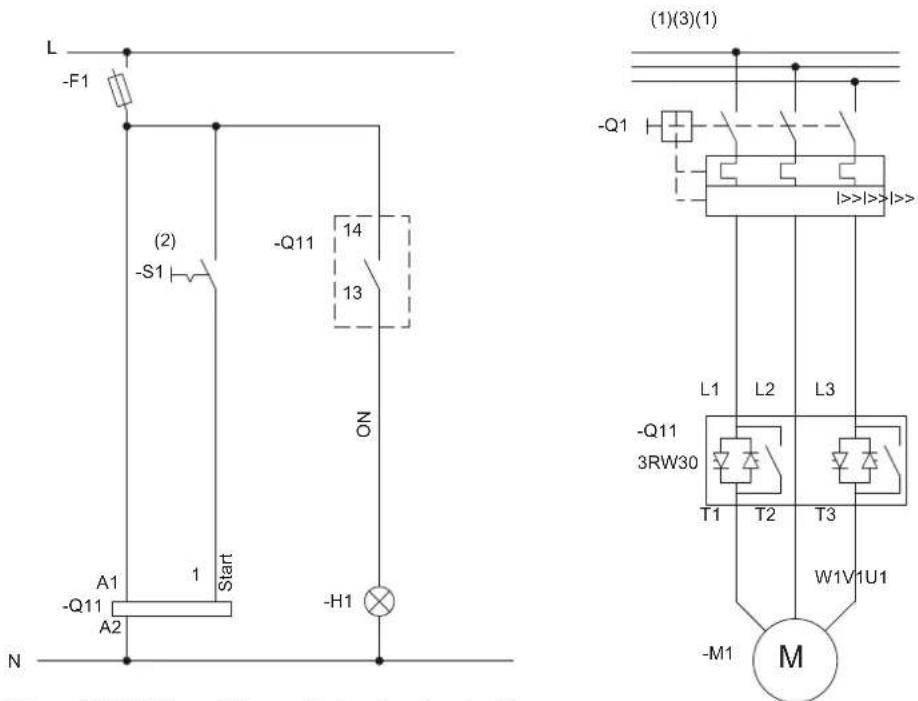
Figure 15-5 Wiring of the control and main circuits
(1) For the permissible values for the main and control voltage (dependent on the MLFB), refer to chapter Technical data [Page 121].

WARNING
(2) Automatic restart. Can result in death, serious injury, or property damage.
Faults caused by incorrect control voltage, a missing load, or a phase failure (refer to chapter 3RW30: LEDs and troubleshooting [Page 44]) are automatically reset when the system returns to normal. An automatic restart is initiated and the 3RW restarted if a start command is present at the input.
If you do not want the motor to start automatically, you must integrate suitable additional components, e.g. phase failure or load monitoring devices, into the control and main circuits.
(3) Alternatively, the motor feeder can be assembled as a fuseless or fused version with type of coordination 1 or 2. For the assignment of fuses and switching devices, refer to chapter Technical data [Page 121]
15.3.2 Control of the 3RW40 by switch
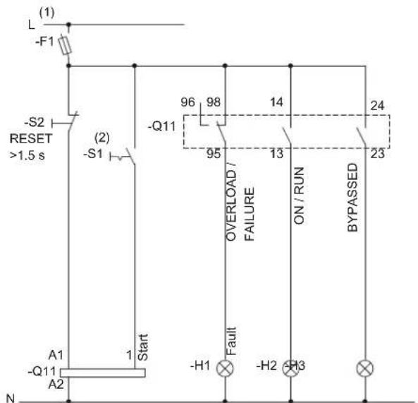
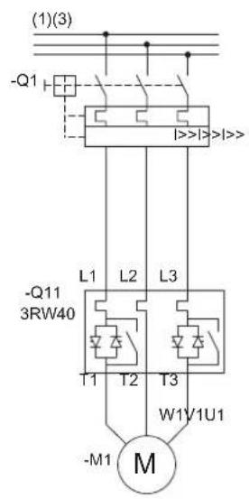
Figure 15-6 Wiring of the 3RW40 2 to 3RW40 4 control circuit and the 3RW40 2 to 3RW40 7 main circuit
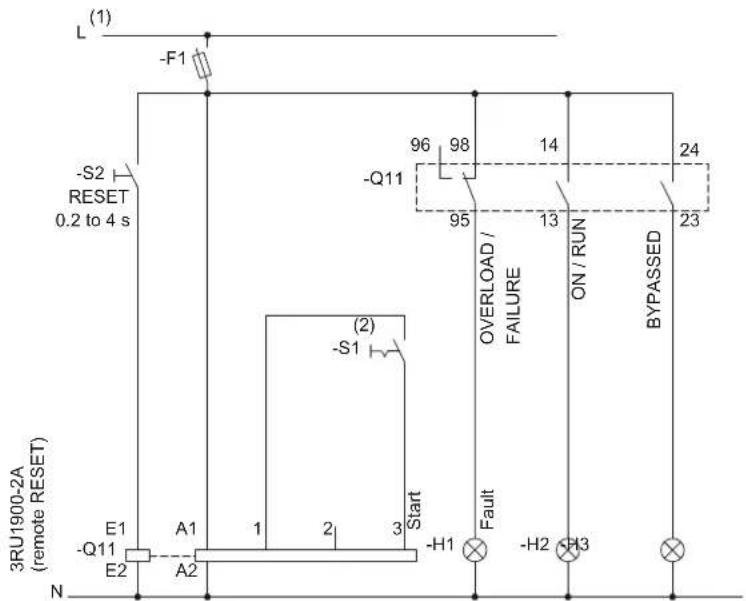
Figure 15-7 Wiring of the 3RW40 5 to 3RW40 7 control circuit
(1) For the permissible values for the main and control voltage (dependent on the MLFB), refer to chapter Technical data [Page 121].

WARNING
(2) Automatic restart.
Can result in death, serious injury, or property damage.
The start command (e.g. issued by the PLC or switch S1) must be reset prior to issuing a RESET command because the motor attempts to restart again automatically following this RESET command if a start command is still present. This particularly applies if the motor protection has tripped. For safety reasons, you are advised to integrate the group fault output (terminals 95 and 96) in the controller.
(3) Alternatively, the motor feeder can be assembled as a fuseless or fused version with type of coordination 1 or 2. For the assignment of fuses and switching devices, refer to chapter Technical data [Page 121]
For the optional thermistor motor protection evaluation, refer to typical circuit for the optional thermistor motor protection evaluation [Page 167].
15.4 Control in automatic mode
15.4.1 Control of the 3RW30 in automatic mode
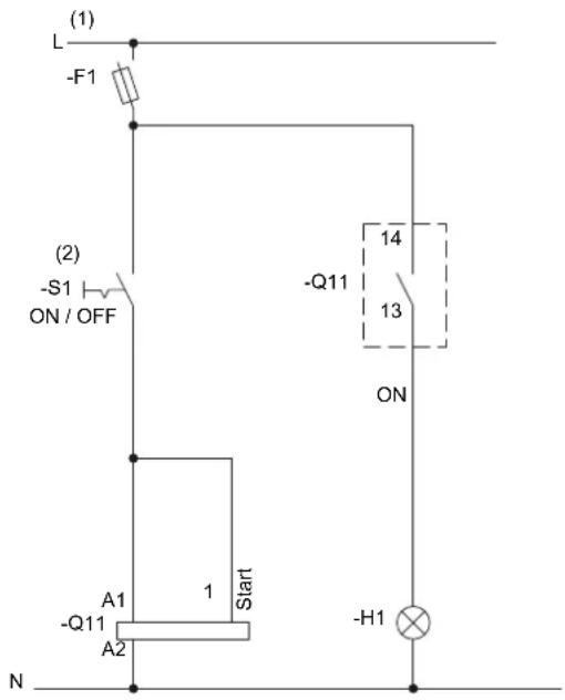
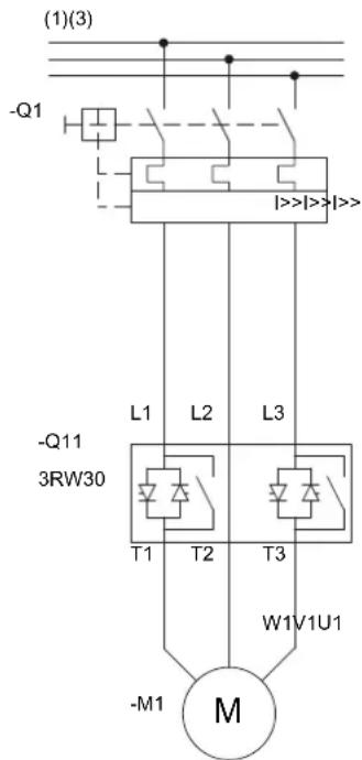
Figure 15-8 Wiring of the 3RW30 control and main circuits
(1) For the permissible values for the main and control voltage (dependent on the MLFB), refer to chapter Technical data [Page 121].

WARNING
(2) Automatic restart. Can result in death, serious injury, or property damage.
Faults caused by incorrect control voltage, a missing load, or a phase failure (refer to chapter 3RW30: LEDs and troubleshooting [Page 44]) are automatically reset when the system returns to normal. An automatic restart is initiated and the 3RW restarted if a start command is present at the input.
If you do not want the motor to start automatically, you must integrate suitable additional components, e.g. phase failure or load monitoring devices, into the control and main circuits.
(3) Alternatively, the motor feeder can be assembled as a fuseless or fused version with type of coordination 1 or 2. For the assignment of fuses and switching devices, refer to chapter Technical data [Page 121]
15.4.2 Control of the 3RW40 in automatic mode
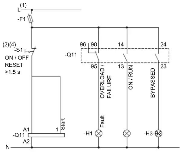
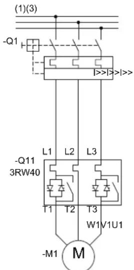
Figure 15-9 Wiring of the 3RW40 2 to 3RW40 4 control circuit and the 3RW40 2 to 3RW40 7 main circuit
15.4 Control in automatic mode
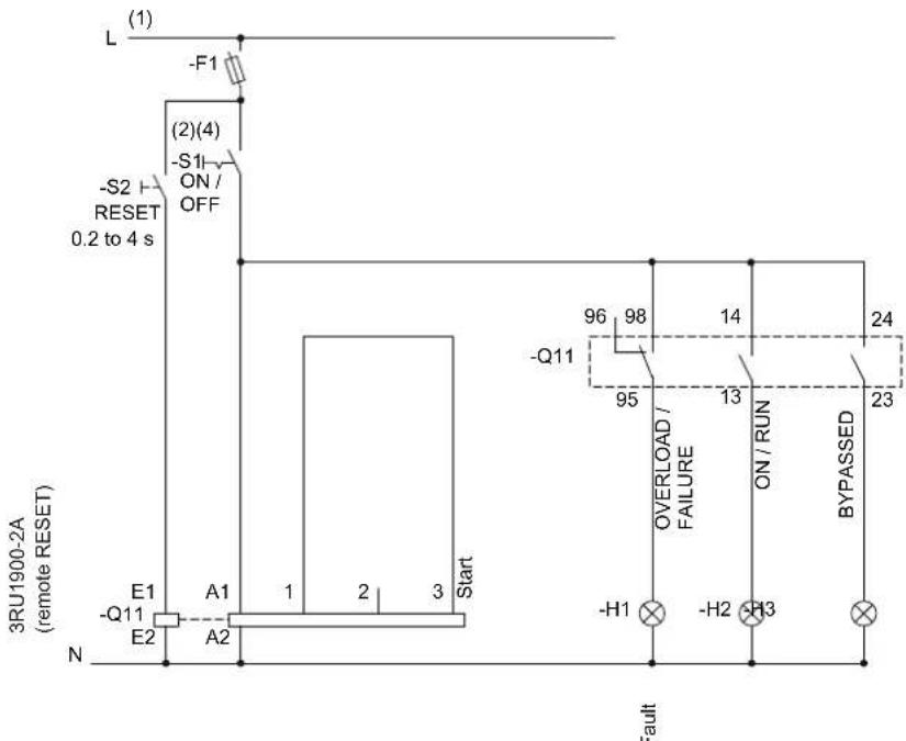
Figure 15-10 Wiring of the 3RW40 5 to 3RW40 7 control circuit
(1) For the permissible values for the main and control voltage (dependent on the MLFB), refer to chapter Technical data [Page 121].

WARNING
(2) Automatic restart.
Can result in death, serious injury, or property damage.
The start command (e.g. issued by the PLC or switch S1) must be reset prior to issuing a RESET command because the motor attempts to restart again automatically following this RESET command if a start command is still present. This particularly applies if the motor protection has tripped. For safety reasons, you are advised to integrate the group fault output (terminals 95 and 96) in the controller.
(3) Alternatively, the motor feeder can be assembled as a fuseless or fused version with type of coordination 1 or 2. For the assignment of fuses and switching devices, refer to chapter Technical data [Page 121]
Note
(4) Idle time until restart.
Owing to the intrinsic protection (3RW), an idle time of at least five minutes must be allowed prior to restarting if the device is switched on and off by means of the control voltage under field conditions.
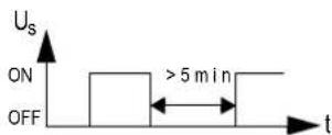
For the optional thermistor motor protection evaluation, refer to Typical circuit for the optional thermistor motor protection evaluation [Page 167].
15.5 Control by PLC
15.5.1 Control of the 3RW30 with 24 V DC by PLC
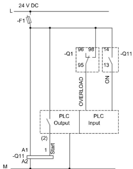
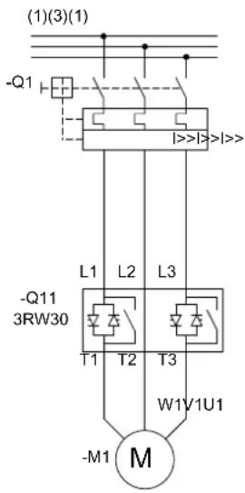
Figure 15-11 Wiring of the 3RW30 control and main circuits
(1) For the permissible values for the main and control voltage (dependent on the MLFB), refer to chapter Technical data [Page 121].

WARNING
(2) Automatic restart. Can result in death, serious injury, or property damage.
Faults caused by incorrect control voltage, a missing load, or a phase failure (refer to chapter 3RW30: LEDs and troubleshooting [Page 44]) are automatically reset when the system returns to normal. An automatic restart is initiated and the 3RW restarted if a start command is present at the input.
If you do not want the motor to start automatically, you must integrate suitable additional components, e.g. phase failure or load monitoring devices, into the control and main circuits.
(3) Alternatively, the motor feeder can be assembled as a fuseless or fused version with type of coordination 1 or 2. For the assignment of fuses and switching devices, refer to chapter Technical data [Page 121]
15.5.2 Control of the 3RW40 by PLC
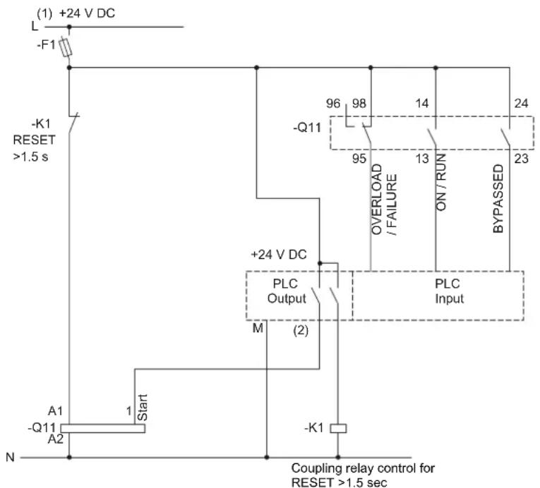
flowchart
graph TD
    A["Start"] --> B["A1 -Q11 A2"]
    B --> C["+24 V DC"]
    C --> D["M (2)"]
    D --> E["PLC Output"]
    E --> F["Overload / FAILURE"]
    F --> G["ON / RUN"]
    G --> H["BYPASSSED"]
    H --> I["PLC Input"]
    I --> J["-Q11"]
    J --> K["96 98 14"]
    K --> L["95 13"]
    L --> M["23"]
    M --> N["24"]
    N --> O["-F1"]
    O --> P["+24 V DC"]
    P --> Q["(-1.5 s)"]
    Q --> R["L (1)"]
    R --> S["+24 V DC"]
    S --> T["N"]
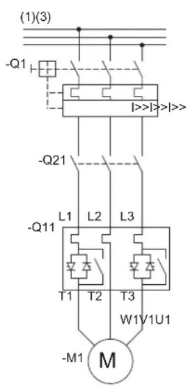
Figure 15-12 Wiring of the 3RW40 2 to 3RW40 4 control circuit (with 24 V control voltage) and the 3RW40 2 to 3RW40 7 main circuit
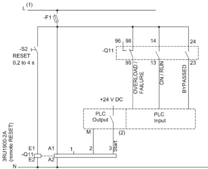
Figure 15-13 Wiring of the 3RW40 5 to 3RW40 7 control circuit
(1) For the permissible values for the main and control voltage (dependent on the MLFB), refer to chapter Technical data [Page 121].

WARNING
(2) Automatic restart.
Can result in death, serious injury, or property damage.
The start command (e.g. issued by the PLC or switch S1) must be reset prior to issuing a RESET command because the motor attempts to restart again automatically following this RESET command if a start command is still present. This particularly applies if the motor protection has tripped. For safety reasons, you are advised to integrate the group fault output (terminals 95 and 96) in the controller.
(3) Alternatively, the motor feeder can be assembled as a fuseless or fused version with type of coordination 1 or 2. For the assignment of fuses and switching devices, refer to chapter Technical data [Page 121]
For the optional thermistor motor protection evaluation, refer to Typical circuit for the optional thermistor motor protection evaluation [Page 167].
15.6 Control with an optional main / line contactor
15.6.1 Control of the 3RW30 with a main contactor
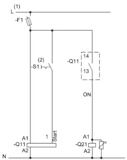
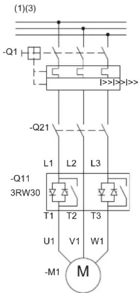
Figure 15-14 Wiring of the 3RW30 control and main circuits
(1) For the permissible values for the main and control voltage (dependent on the MLFB), refer to chapter Technical data [Page 121].

WARNING
(2) Automatic restart. Can result in death, serious injury, or property damage.
Faults caused by incorrect control voltage, a missing load, or a phase failure (refer to chapter 3RW30: LEDs and troubleshooting [Page 44]) are automatically reset when the system returns to normal. An automatic restart is initiated and the 3RW restarted if a start command is present at the input.
If you do not want the motor to start automatically, you must integrate suitable additional components, e.g. phase failure or load monitoring devices, into the control and main circuits.
(3) Alternatively, the motor feeder can be assembled as a fuseless or fused version with type of coordination 1 or 2. For the assignment of fuses and switching devices, refer to chapter Technical data [Page 121]
15.6.2 Control of the 3RW40 with a main contactor
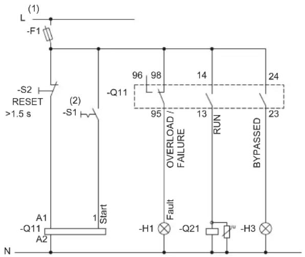
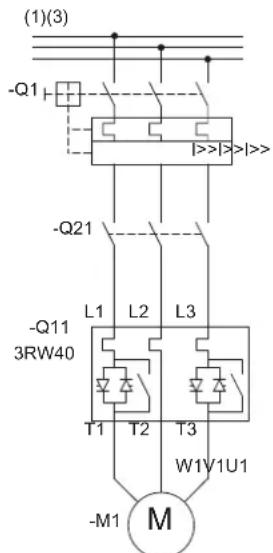
Figure 15-15 Wiring of the 3RW40 2 to 3RW40 4 control circuit and the 3RW40 2 to 3RW40 7 main circuit
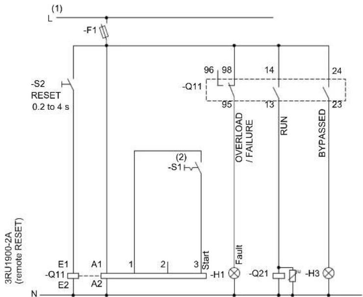
Figure 15-16 Wiring of the 3RW40 5 to 3RW40 7 control circuit
Note
If a soft stop is required, the function of output 13/14 must be reparameterized to "RUN" (refer to Commissioning the 3RW40 [Page 98]).
(1) For the permissible values for the main and control voltage (dependent on the MLFB), refer to chapter Technical data [Page 121].

WARNING
(2) Automatic restart.
Can result in death, serious injury, or property damage.
The start command (e.g. issued by the PLC or switch S1) must be reset prior to issuing a RESET command because the motor attempts to restart again automatically following this RESET command if a start command is still present. This particularly applies if the motor protection has tripped. For safety reasons, you are advised to integrate the group fault output (terminals 95 and 96) in the controller.
(3) Alternatively, the motor feeder can be assembled as a fuseless or fused version with type of coordination 1 or 2. For the assignment of fuses and switching devices, refer to chapter Technical data [Page 121]
For the optional thermistor motor protection evaluation, refer to Typical circuit for the optional thermistor motor protection evaluation [Page 167].
15.7 Reversing circuit
15.7.1 3RW30 reversing circuit
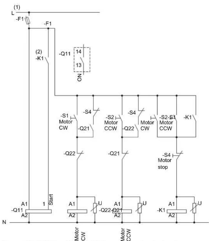
flowchart
graph TD
    L["Start"] -->|A1 -Q11 A2| MotorCW
    MotorCW -->|U -Q22 -Q21 A2| MotorCCW
    MotorCCW -->|A1 -Q22 -Q21 A2| MotorCW
    MotorCW -->|S4 Motor CW -Q21| MotorCCW
    MotorCCW -->|S4 Motor CW -Q22| MotorCW
    MotorCW -->|S4 Motor stop| MotorCCW
    MotorCCW -->|K1 Motor CCW -Q1| MotorCW
    MotorCCW -->|K1 Motor CCW -Q11| MotorCW
    MotorCW -->|ON| ON
    ON -->|Q11 14 13| MotorCCW
    style L fill:#f9f,stroke:#333
    style N fill:#ccf,stroke:#333
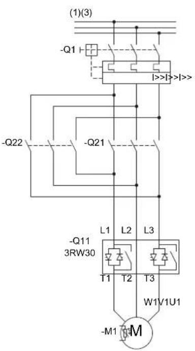
Figure 15-17 Wiring of the 3RW30 control and main circuits
(1) For the permissible values for the main and control voltage (dependent on the MLFB), refer to chapter Technical data [Page 121].

WARNING
(2) Automatic restart. Can result in death, serious injury, or property damage.
Faults caused by incorrect control voltage, a missing load, or a phase failure (refer to chapter 3RW30: LEDs and troubleshooting [Page 44]) are automatically reset when the system returns to normal. An automatic restart is initiated and the 3RW restarted if a start command is present at the input.
If you do not want the motor to start automatically, you must integrate suitable additional components, e.g. phase failure or load monitoring devices, into the control and main circuits.
(3) Alternatively, the motor feeder can be assembled as a fuseless or fused version with type of coordination 1 or 2. For the assignment of fuses and switching devices, refer to chapter technical data [Page 121]
15.7.2 3RW40 reversing circuit
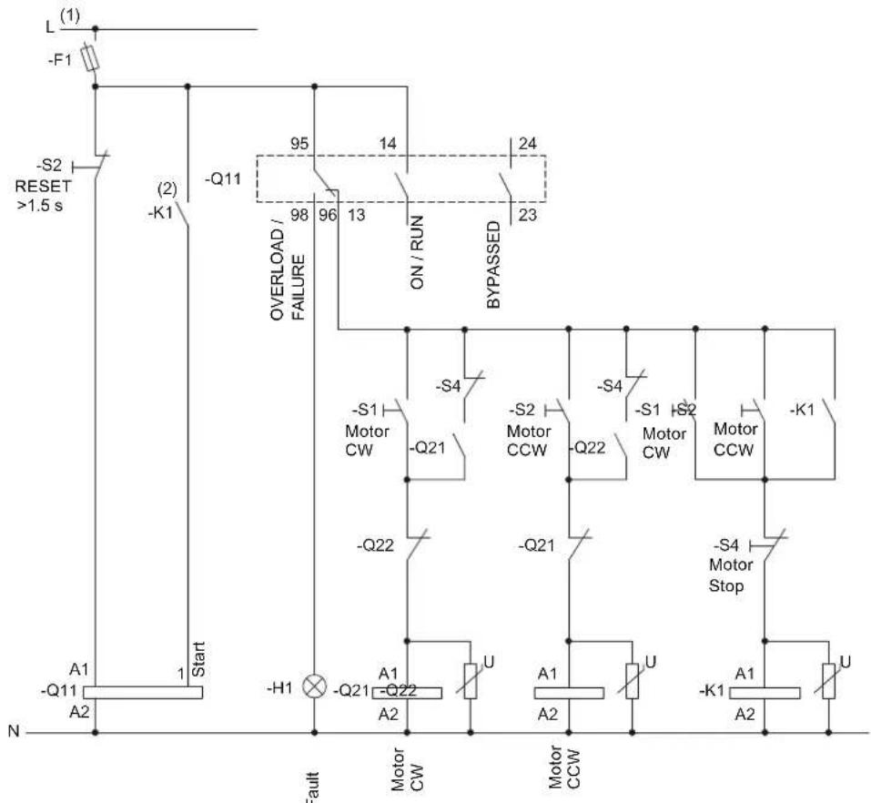
flowchart
graph TD
    L[" L "] --> F1["-F1 "]
    F1 --> S2[" -S2 RESET >1.5 s "]
    S2 --> K1[" -K1 "]
    K1 --> Start[" Start "]
    Start --> A1[" A1 -Q11 A2 "]
    A1 --> Fault[" Fault "]
    Fault --> MotorCW[" Motor CW "]
    MotorCW --> U1[" U "]
    U1 --> A2[" A2 "]
    A2 --> MotorCCW[" Motor CCW "]
    MotorCCW --> U2[" U "]
    U2 --> A1A[" A1 "]
    A1A --> MotorStop[" -S4 Motor Stop "]
    MotorStop --> U3[" U "]
    U3 --> A2A[" A2 "]
    A2A --> MotorCCW
    MotorCCW --> U4[" U "]
    U4 --> A1B[" A1 "]
    A1B --> MotorCCW
    MotorCCW --> U5[" U "]
    U5 --> A2B[" A2 "]
    A2B --> MotorCCW
    MotorCCW --> U6[" U "]
    U6 --> A1C[" A1 "]
    A1C --> MotorCCW
    MotorCCW --> U7[" U "]
    U7 --> A2C[" A2 "]
    A2C --> MotorCCW
    MotorCCW --> U8[" U "]
    U8 --> A1D[" A1 "]
    A1D --> MotorCCW
    MotorCCW --> U9[" U "]
    U9 --> A2D[" A2 "]
    A2D --> MotorCCW
    MotorCCW --> U10[" U "]
    U10 --> A1E[" A1 "]
    A1E --> MotorCCW
    MotorCCW --> U11[" U "]
    U11 --> A2E[" A2 "]
    A2E --> MotorCCW
    MotorCCW --> U12[" U "]
    U12 --> A1F[" A1 "]
    A1F --> MotorCCW
    MotorCCW --> U13[" U "]
    U13 --> A2F[" A2 "]
    A2F --> MotorCCW
    MotorCCW --> U14[" U "]
    U14 --> A2G[" A2 "]
    A2G --> MotorCCW
    MotorCCW --> U15[" U "]
    U15 --> A2H[" A2 "]
    A2H --> MotorCCW
    MotorCCW --> U16[" U "]
    U16 --> A2I[" A2 "]
    A2I --> MotorCCW
    MotorCCW --> U17[" U "]
    U17 --> A2J[" A2 "]
    A2J --> MotorCCW
    MotorCCW --> U18[" U "]
    U18 --> A2K[" A2 "]
    A2K --> MotorCCW
    MotorCCW --> U19[" U "]
    U19 --> A2L[" A2 "]
    A2L --> MotorCCW
    MotorCCW --> U20[" U "]
    U20 --> A2M[" A2 "]
    A2M --> MotorCCW
    MotorCCW --> U21[" U "]
    U21 --> A2N[" A2 "]
    A2N --> MotorCCW
    MotorCCW --> U22[" U "]
    U22 --> A2O[" A2 "]
    A2O --> MotorCCW
    MotorCCW --> U23[" U "]
    U23 --> A2P[" A2 "]
    A2P --> MotorCCW
    MotorCCW --> U24[" U "]
    U24 --> A2Q[" A2 "]
    A2Q --> MotorCCW
    MotorCCW --> U25[" U "]
    U25 --> A2R[" A2 "]
    A2R --> MotorCCW
    MotorCCW --> U26[" U "]
    U26 --> A2S[" A2 "]
    A2S --> MotorCCW
    MotorCCW --> U27[" U "]
    U27 --> A2U[" A2 "]
    A2U --> MotorCCW
    MotorCCW --> U28[" U "]
    U28 --> A2V[" A2 "]
    A2V --> MotorCCW
    MotorCCW --> U29[" U "]
    U29 --> A2X[" A2 "]
    A2X --> MotorCCW
    MotorCCW --> U30[" U "]
    U30 --> A2Y[" A2 "]
    A2Y --> MotorCCW
    MotorCCW --> U31[" U "]
    U31 --> A2Z[" A2 "]
    A2Z --> MotorCCW
    MotorCCW --> U32[" U "]
    U32 --> A2X
    A2X --> MotorCCW
    MotorCCW --> U33[" U "]
    U33 --> A2Y
    A2Y --> MotorCCW
    MotorCCW --> U34[" U "]
    U34 --> A2Z
    A2Z --> MotorCCW
    MotorCCW --> U35[" U "]
    U35 --> A2X
    A2X --> MotorCCW
    MotorCCW --> U36[" U "]
    U36 --> A2Y
    A2Y --> MotorCCW
    MotorCCW --> U37[" U "]
    U37 --> A2Z
    A2Z --> MotorCCW
    MotorCCW --> U38[" U "]
    U38 --> A2X
    A2X --> MotorCCW
    MotorCCW --> U39[" U "]
    U39 --> A2Y
    A2Y --> MotorCCW
    MotorCCW --> U40[" U "]
    U40 --> A2Z
    A2Z --> MotorCCW
    MotorCCW --> U41[" U "]
    U41 --> A2X
    A2X --> MotorCCW
    MotorCCW --> U42[" U "]
    U42 --> A2Y
    A2Y --> MotorCCW
    MotorCCW --> U43[" U "]
    U43 --> A2Z
    A2Z --> MotorCCW
    MotorCCW --> U44[" U "]
    U44 --> A2X
    A2X --> MotorCCW
    MotorCCW --> U45[" U "]
    U45 --> A2Y
    A2Y --> MotorCCW
    MotorCCW --> U46[" U "]
    U46 --> A2Z
    A2Z --> MotorCCW
    MotorCCW --> U47[" U "]
    U47 --> A2X
    A2X --> MotorCCW
    MotorCCW --> U48[" U "]
    U48 --> A2Y
    A2Y --> MotorCCW
    MotorCCW --> U49[" U "]
    U49 --> A2Z
    A2Z --> MotorCCW
    MotorCCW --> U50[" U "]
    U50 --> A2X
    A2X --> MotorCCW
    MotorCCW --> U51[" U "]
    U51 --> A2Y
    A2Y --> MotorCCW
    MotorCCW --> U52[" U "]
    U52 --> A2Z
    A2Z --> MotorCCW
    MotorCCW --> U53[" U "]
    U53 --> A2X
    A2X --> MotorCCW
    MotorCCW --> U54[" U "]
    U54 --> A2Y
    A2Y --> MotorCCW
    MotorCCW --> U55[" U "]
    U55 --> A2Z
    A2Z --> MotorCCW
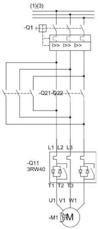
Figure 15-18 Wiring of the 3RW40 2 to 3RW40 5 control circuit and the 3RW40 2 to 3RW40 7 main circuit
15.7 Reversing circuit
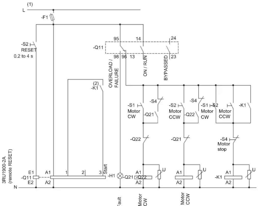
flowchart
graph TD
    A["Start"] --> B["(-Q11)"]
    B --> C["A1"]
    C --> D["1"]
    D --> E["2"]
    E --> F["3"]
    F --> G["(-Q21)"]
    G --> H["A1"]
    H --> I["2"]
    I --> J["(-Q22)"]
    J --> K["A2"]
    K --> L["Motor CW"]
    L --> M["U"]
    M --> N["Motor CCW"]
    N --> O["A1"]
    O --> P["U"]
    P --> Q["-K1"]
    Q --> R["A2"]
    R --> S["U"]
    S --> T["-S4 Motor stop"]
    T --> U["-Q21"]
    U --> V["A1"]
    V --> W["U"]
    W --> X["-S2 Motor CW"]
    X --> Y["-Q22"]
    Y --> Z["-Q21"]
    Z --> AA["A1"]
    AA --> AB["U"]
    AB --> AC["-S1 Motor CW"]
    AC --> AD["-Q21"]
    AD --> AE["A2"]
    AE --> AF["U"]
    AF --> AG["-S4 Motor stop"]
    AG --> AH["-Q22"]
    AH --> AI["A1"]
    AI --> AJ["U"]
    AJ --> AK["-S1 Motor CW"]
    AK --> AL["-Q22"]
    AL --> AM["A2"]
    AM --> AN["U"]
    AN --> AO["-S4 Motor stop"]
    AO --> AP["-Q21"]
    AP --> AQ["A1"]
    AQ --> AR["U"]
    AR --> AS["-S1 Motor CW"]
    AS --> AT["-Q22"]
    AT --> AU["A1"]
    AU --> AV["U"]
    AV --> AW["-S4 Motor stop"]
    AW --> AX["-Q21"]
    AX --> AY["A2"]
    AY --> AZ["U"]
Figure 15-19 Wiring of the 3RW40 5 to 3RW40 7 control circuit
(1) For the permissible values for the main and control voltage (dependent on the MLFB), refer to chapter Technical data [Page 121].

WARNING
(2) Automatic restart.
Can result in death, serious injury, or property damage.
The start command (e.g. issued by the PLC or switch S1) must be reset prior to issuing a RESET command because the motor attempts to restart again automatically following this RESET command if a start command is still present. This particularly applies if the motor protection has tripped. For safety reasons, you are advised to integrate the group fault output (terminals 95 and 96) in the controller.
(3) Alternatively, the motor feeder can be assembled as a fuseless or fused version with type of coordination 1 or 2. For the assignment of fuses and switching devices, refer to chapter Technical data [Page 121]
For the optional thermistor motor protection evaluation, refer to typical circuit for the optional thermistor motor protection evaluation [Page 167].
NOTICE
No soft stop possible. Set the ramp-down time to 0 s with the potentiometer.
15.8 Control of a magnetic parking brake
15.8.1 3RW30 motor with magnetic parking brake
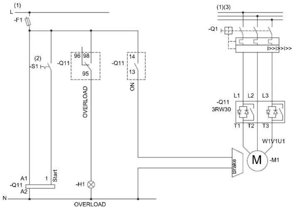
Figure 15-20 Wiring of the 3RW30 control and main circuits
(1) For the permissible values for the main and control voltage (dependent on the MLFB), refer to chapter Technical data [Page 121].

WARNING
(2) Automatic restart. Can result in death, serious injury, or property damage.
Faults caused by incorrect control voltage, a missing load, or a phase failure (refer to chapter 3RW30: LEDs and troubleshooting [Page 44]) are automatically reset when the system returns to normal. An automatic restart is initiated and the 3RW restarted if a start command is present at the input.
If you do not want the motor to start automatically, you must integrate suitable additional components, e.g. phase failure or load monitoring devices, into the control and main circuits.
(3) Alternatively, the motor feeder can be assembled as a fuseless or fused version with type of coordination 1 or 2. For the assignment of fuses and switching devices, refer to chapter Technical data [Page 121]
15.8.2 3RW40 2 to 3RW40 4, control of a motor with a magnetic parking brake
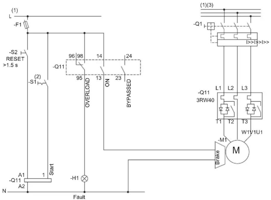
Figure 15-21 Wiring of the 3RW40 2 to 3RW40 4 control / main circuit
(1) For the permissible values for the main and control voltage (dependent on the MLFB), refer to chapter Technical data [Page 121].

WARNING
(2) Automatic restart.
Can result in death, serious injury, or property damage.
The start command (e.g. issued by the PLC or switch S1) must be reset prior to issuing a RESET command because the motor attempts to restart again automatically following this RESET command if a start command is still present. This particularly applies if the motor protection has tripped. For safety reasons, you are advised to integrate the group fault output (terminals 95 and 96) in the controller.
(3) Alternatively, the motor feeder can be assembled as a fuseless or fused version with type of coordination 1 or 2. For the assignment of fuses and switching devices, refer to chapter Technical data [Page 121]
For the optional thermistor motor protection evaluation, refer to typical circuit for the optional thermistor motor protection evaluation [Page 167].
NOTICE
No soft stop possible. Set the ramp-down time to 0 s with the potentiometer.
15.8.3 3RW40 5 to 3RW40 7, control of a motor with a magnetic parking brake
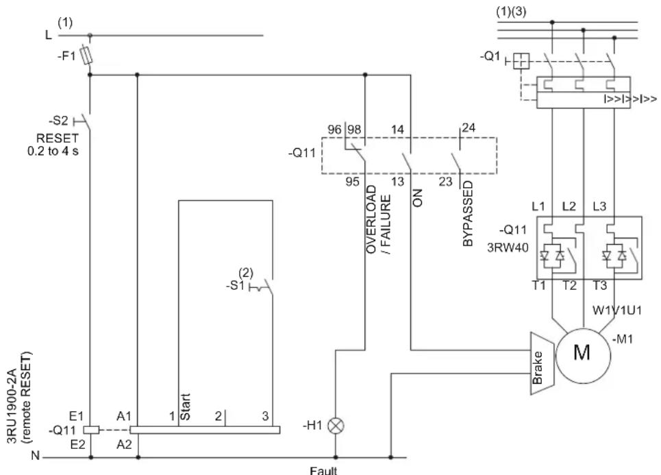
Figure 15-22 Wiring of the 3RW40 5 to 3RW40 7 control / main circuit
(1) For the permissible values for the main and control voltage (dependent on the MLFB), refer to chapter Technical data [Page 121].

WARNING
(2) Automatic restart.
Can result in death, serious injury, or property damage.
The start command (e.g. issued by the PLC or switch S1) must be reset prior to issuing a RESET command because the motor attempts to restart again automatically following this RESET command if a start command is still present. This particularly applies if the motor protection has tripped. For safety reasons, you are advised to integrate the group fault output (terminals 95 and 96) in the controller.
(3) Alternatively, the motor feeder can be assembled as a fuseless or fused version with type of coordination 1 or 2. For the assignment of fuses and switching devices, refer to chapter Technical data [Page 121]
For the optional thermistor motor protection evaluation, refer to Typical circuit for the optional thermistor motor protection evaluation [Page 167].
NOTICE
No soft stop possible. Set the ramp-down time to 0 s with the potentiometer.
15.9 Emergency stop
15.9.1 3RW30 emergency stop and 3TK2823 safety relay
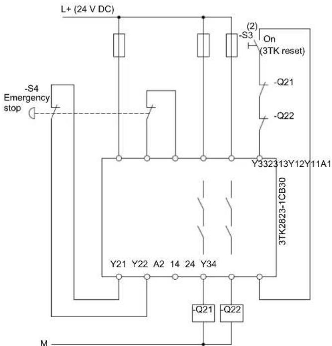
Figure 15-23 Wiring of the emergency stop control circuit and the 3TK28 safety relay
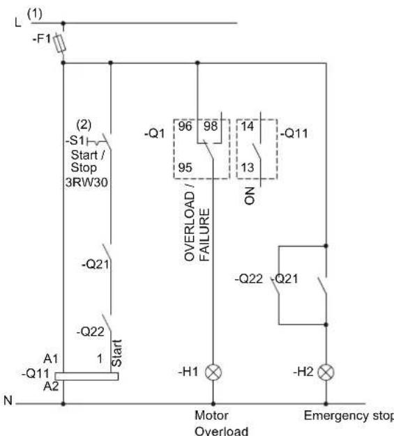
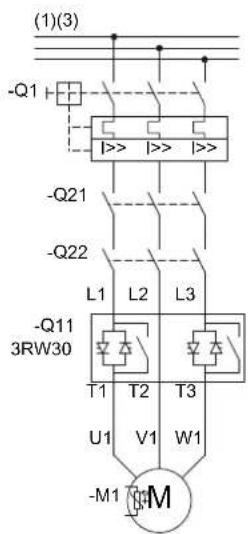
Figure 15-24 Wiring of the 3RW30 control and main circuits
(1) For the permissible values for the main and control voltage (dependent on the MLFB), refer to chapter Technical data [Page 121].

WARNING
(2) Automatic restart. Can result in death, serious injury, or property damage.
- If the 3TK28 is reset
Faults caused by incorrect control voltage, a missing load, or a phase failure (refer to chapter 3RW30: LEDs and troubleshooting [Page 44]) are automatically reset when the system returns to normal.
An automatic restart is initiated and the 3RW restarted if a start command is present at the input.
If you do not want the motor to start automatically, you must integrate suitable additional components, e.g. phase failure or load monitoring devices, into the control and main circuits.
(3) Alternatively, the motor feeder can be assembled as a fuseless or fused version with type of coordination 1 or 2. For the assignment of fuses and switching devices, refer to chapter Technical data [Page 121]
15.9.2 3RW40 2 to 3RW40 4 emergency stop and 3TK2823 safety relay
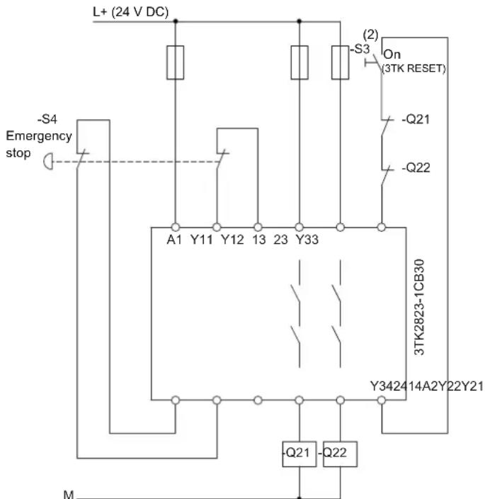
Figure 15-25 Wiring of the emergency stop control circuit and the 3TK28 safety relay
15.9 Emergency stop
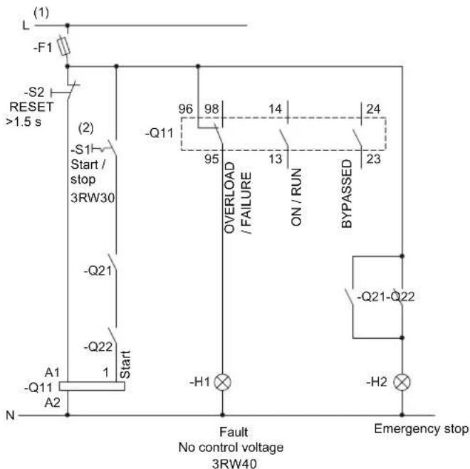
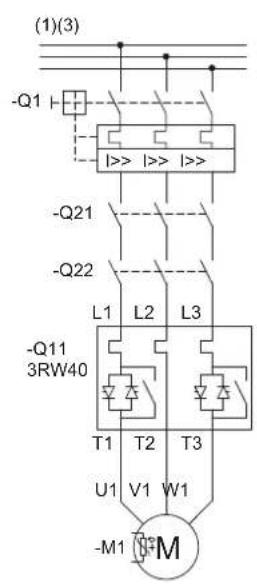
Figure 15-26 Wiring of the 3RW40 2 to 3RW40 4 control circuit and the 3RW40 2 to 3RW40 7 main circuit
(1) For the permissible values for the main and control voltage (dependent on the MLFB), refer to chapter Technical data [Page 121].

WARNING
(2) Automatic restart.
Can result in death, serious injury, or property damage.
The start command (e.g. issued by the PLC or switch S1) must be reset prior to issuing a RESET command because the motor attempts to restart again automatically following this RESET command (3TK or 3RW) if a start command is still present. This particularly applies if the motor protection has tripped. For safety reasons, you are advised to integrate the group fault output (terminals 95 and 96) in the controller.
(3) Alternatively, the motor feeder can be assembled as a fuseless or fused version with type of coordination 1 or 2. For the assignment of fuses and switching devices, refer to chapter Technical data [Page 121]
For the optional thermistor motor protection evaluation, refer to typical circuit for the optional thermistor motor protection evaluation [Page 167].
NOTICE
If the soft stop function is set (ramp-down time potentiometer set to >0 s) and the emergency stop circuit is tripped, a "Missing load voltage, phase failure / missing load" fault may be indicated on the soft starter. In this case, the soft starter must be reset according to the selected RESET MODE.
15.9.3 3RW40 5 to 3RW40 7 emergency stop and 3TK2823 safety relay
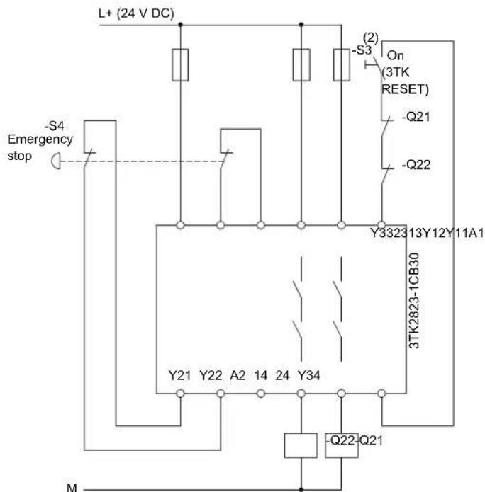
Figure 15-27 Wiring of the emergency stop control circuit and the 3TK28 safety relay
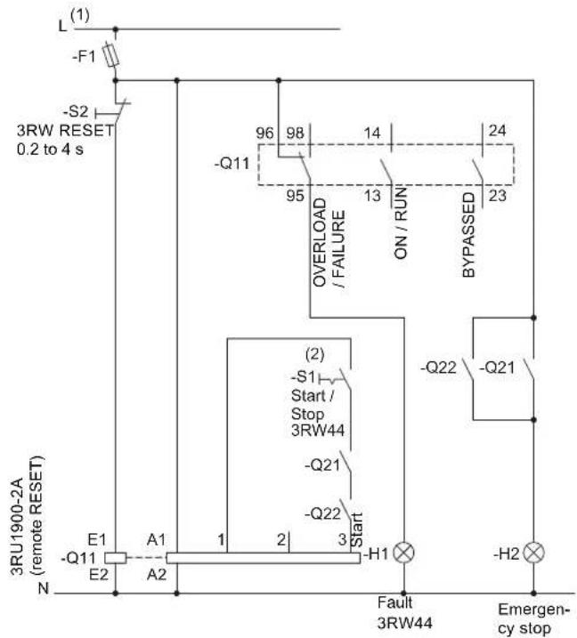
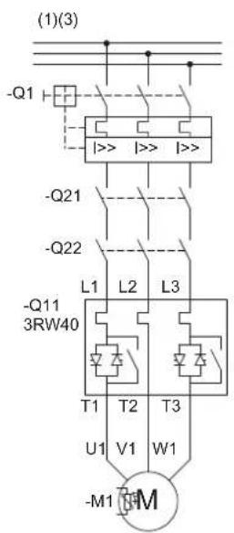
Figure 15-28
Wiring of the 3RW40 5 to 3RW40 7 control circuit and the 3RW40 2 to 3RW40 7 main circuit
(1) For the permissible values for the main and control voltage (dependent on the MLFB), refer to chapter Technical data [Page 121].

WARNING
(2) Automatic restart.
Can result in death, serious injury, or property damage.
The start command (e.g. issued by the PLC or switch S1) must be reset prior to issuing a RESET command because the motor attempts to restart again automatically following this RESET command (3TK or 3RW) if a start command is still present. This particularly applies if the motor protection has tripped. For safety reasons, you are advised to integrate the group fault output (terminals 95 and 96) in the controller.
(3) Alternatively, the motor feeder can be assembled as a fuseless or fused version with type of coordination 1 or 2. For the assignment of fuses and switching devices, refer to chapter Technical data [Page 121]
For the optional thermistor motor protection evaluation, refer to typical circuit for the optional thermistor motor protection evaluation [Page 167].
NOTICE
If the soft stop function is set (ramp-down time potentiometer set to >0 s) and the emergency stop circuit is tripped, a "Missing load voltage, phase failure / missing load" fault may be indicated on the soft starter. In this case, the soft starter must be reset according to the selected RESET MODE.
15.10 3RW and contactor for emergency starting
15.10.1 3RW30 and contactor for emergency starting
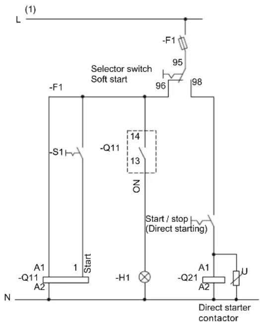
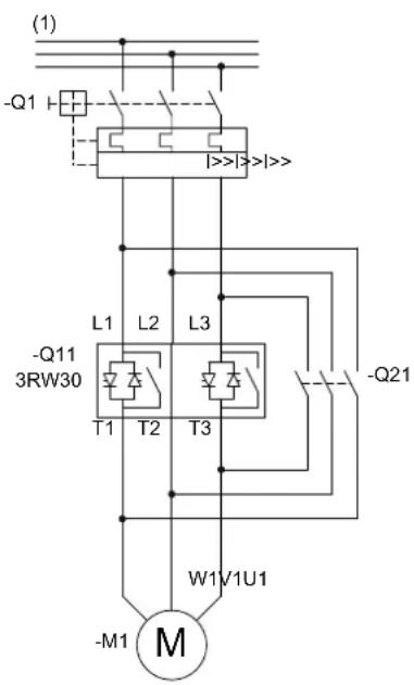
Figure 15-29 Wiring of the 3RW30 control and main circuits
(1) For the permissible values for the main and control voltage (dependent on the MLFB), refer to chapter Technical data [Page 121].

WARNING
(2) Automatic restart. Can result in death, serious injury, or property damage.
Faults caused by incorrect control voltage, a missing load, or a phase failure (refer to Troubleshooting chapter) are automatically reset when the system returns to normal. An automatic restart is initiated and the 3RW restarted if a start command is present at the input. If you do not want the motor to start automatically, you must integrate suitable additional components, e.g. phase failure or load monitoring devices, into the control and main circuits
(3) Alternatively, the motor feeder can be assembled as a fuseless or fused version with type of coordination 1 or 2. For the assignment of fuses and switching devices, refer to chapter Technical data [Page 121]
15.10.2 3RW40 and contactor for emergency starting
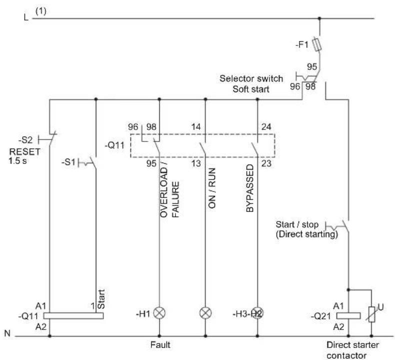
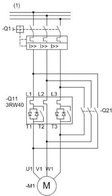
Figure 15-30 Wiring of the 3RW40 2 to 3RW40 4 control circuit and the 3RW40 2 to 3RW40 7 main circuit
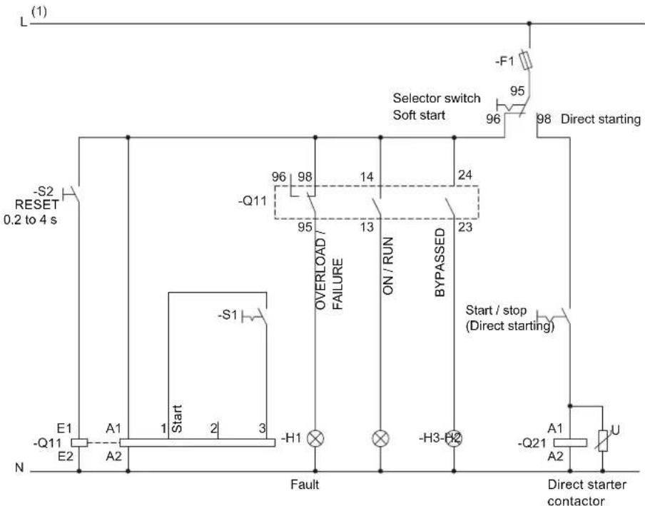
flowchart
graph TD
    A["Start"] --> B["E1"]
    A --> C["A1"]
    A --> D["A2"]
    E["S1"] --> F["-Q11"]
    F --> G["E2"]
    H["S2"] --> I["RESET 0.2 to 4 s"]
    I --> J["-Q11"]
    K["Overload / FAILURE"] --> L["-Q11"]
    M["ON / RUN"] --> N["-Q11"]
    O["BYPASSSED"] --> P["-Q11"]
    Q["Start / stop (Direct starting)"] --> R["-Q21"]
    S["Fault"] --> T["-H1"]
    U["Direct starter contactor"] --> V["-Q21"]
    W["Selector switch Soft start"] --> X["-F1"]
    X --> Y["95"]
    Y --> Z["96"]
    Z --> AA["98"]
    AA --> AB["Direct starting"]
Figure 15-31 Wiring of the 3RW40 5 to 3RW40 7 control circuit
(1) For the permissible values for the main and control voltage (dependent on the MLFB), refer to chapter Technical data [Page 121].

WARNING
(2) Automatic restart.
Can result in death, serious injury, or property damage.
The start command (e.g. issued by the PLC or switch S1) must be reset prior to issuing a RESET command because the motor attempts to restart again automatically following this RESET command if a start command is still present. This particularly applies if the motor protection has tripped. For safety reasons, you are advised to integrate the group fault output (terminals 95 and 96) in the controller.
(3) Alternatively, the motor feeder can be assembled as a fuseless or fused version with type of coordination 1 or 2. For the assignment of fuses and switching devices, refer to chapter Technical data [Page 121]
For the optional thermistor motor protection evaluation, refer to Typical circuit for the optional thermistor motor protection evaluation [Page 167].
15.11 Dahlander / multispeed motor
15.11.1 3RW30 and Dahlander motor starting
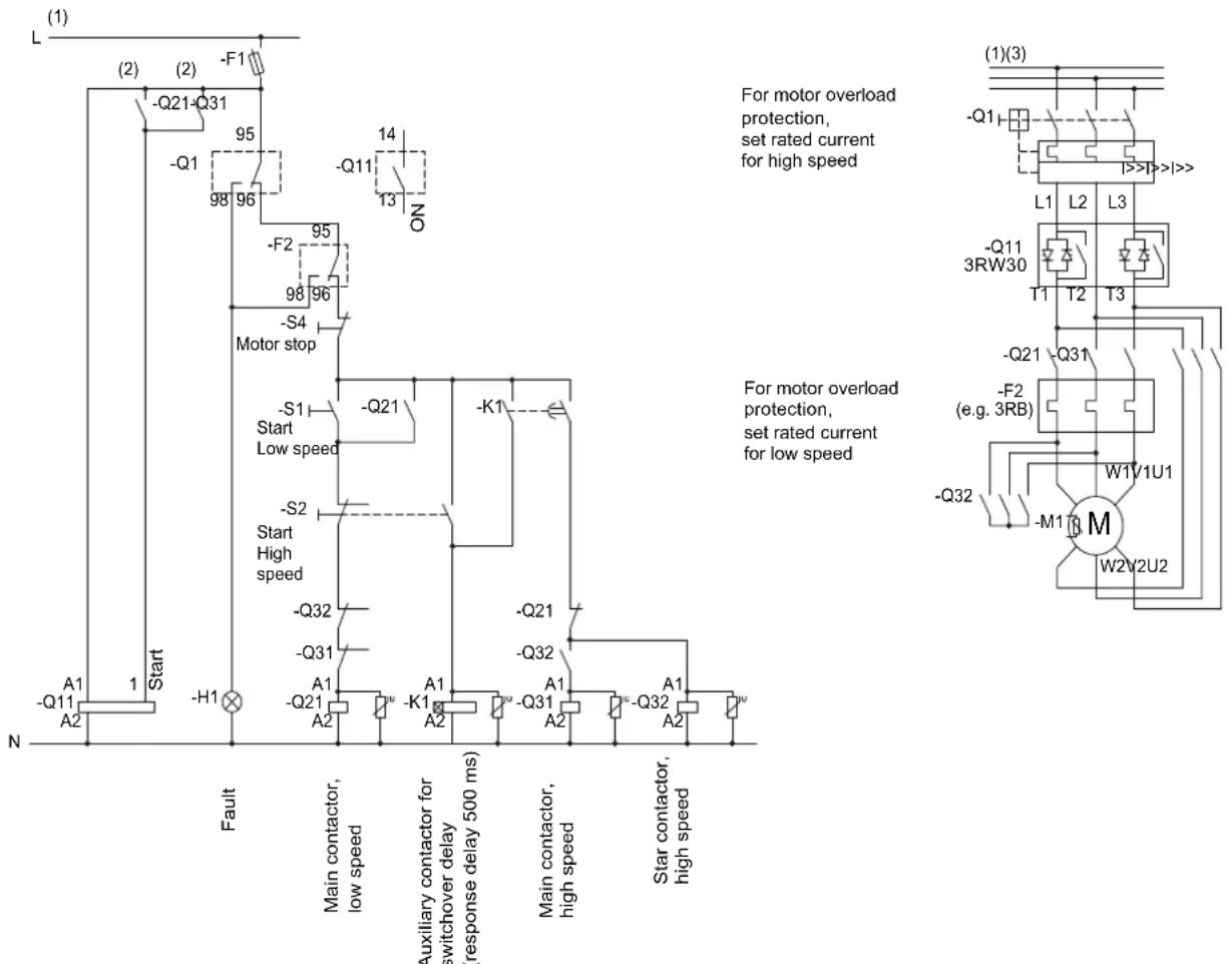
flowchart
graph TD
    A["Start"] --> B["A1 -Q11 A2"]
    B --> C["Fault"]
    C --> D["Main contactor, low speed"]
    D --> E["Auxiliary contactor for switchover delay (response delay 500 ms)"]
    E --> F["Main contactor, high speed"]
    F --> G["Star contactor, high speed"]

    H["Motor stop"] --> I["S1 -S4"]
    I --> J["Main contactor, high speed"]
    J --> K["Main contactor, high speed"]

    L["For motor overload protection, set rated current for high speed"] --> M["On"]
    N["For motor overload protection, set rated current for low speed"] --> O["K1 -Q21"]
    P["For motor overload protection, set rated current for high speed"] --> Q["L1 -Q11 3RW30 T1 T2 T3"]
    R["For motor overload protection, set rated current for low speed"] --> S["W1V1U1 M W2V2U2"]
Figure 15-32 Wiring of the 3RW30 control and main circuits
(1) For the permissible values for the main and control voltage (dependent on the MLFB), refer to chapter Technical data [Page 121].

WARNING
(2) Automatic restart. Can result in death, serious injury, or property damage.
Faults caused by incorrect control voltage, a missing load, or a phase failure (refer to chapter 3RW30: LEDs and troubleshooting [Page 44]) are automatically reset when the system returns to normal. An automatic restart is initiated and the 3RW restarted if a start command is present at the input.
If you do not want the motor to start automatically, you must integrate suitable additional components, e.g. phase failure or load monitoring devices, into the control and main circuits.
(3) Alternatively, the motor feeder can be assembled as a fuseless or fused version with type of coordination 1 or 2. For the assignment of fuses and switching devices, refer to chapter Technical data [Page 121]
15.11.2 3RW40 2 to 3RW40 4 and Dahlander motor starting
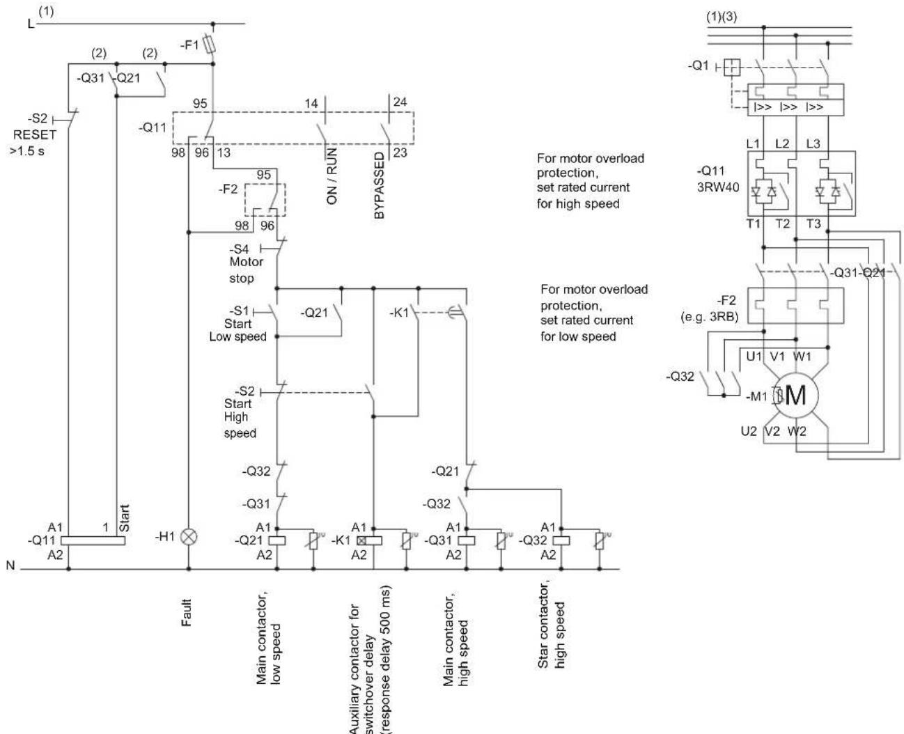
flowchart
graph TD
    A["Start"] --> B["A1 -Q11 A2"]
    B --> C["Fault"]
    C --> D["Main contactor, low speed"]
    D --> E["Auxiliary contactor for switchover delay (response delay 500 ms)"]
    E --> F["Main contactor, high speed"]
    F --> G["Star contactor, high speed"]

    H["S2 RESET >1.5 s"] --> I["-Q31 Q21"]
    I --> J["-Q11 95"]
    J --> K["ON / RUN ON / RUN BY PASSED 24"]
    K --> L["-S4 Motor stop"]
    L --> M["-S1 Start Low speed"]
    M --> N["-Q21"]
    N --> O["-K1"]
    O --> P["-Q32"]
    P --> Q["-Q31"]
    Q --> R["A1 -Q21 A2"]
    R --> S["K1"]
    S --> T["-Q31"]
    T --> U["A1 -Q32"]
    U --> V["-Q32"]

    W["For motor overload protection, set rated current for high speed"] --> X["For motor overload protection, set rated current for low speed"]
    Y["For motor overload protection, set rated current for high speed"] --> Z["For motor overload protection, set rated current for low speed"]
Figure 15-33 Wiring of the 3RW40 2 to 3RW40 4 control circuit and the 3RW40 2 to 3RW40 7 main circuit
(1) For the permissible values for the main and control voltage (dependent on the MLFB), refer to chapter Technical data [Page 121].

WARNING
(2) Automatic restart.
Can result in death, serious injury, or property damage.
The start command (e.g. issued by the PLC or switch S1) must be reset prior to issuing a RESET command because the motor attempts to restart again automatically following this RESET command if a start command is still present. This particularly applies if the motor protection has tripped. For safety reasons, you are advised to integrate the group fault output (terminals 95 and 96) in the controller.
(3) Alternatively, the motor feeder can be assembled as a fuseless or fused version with type of coordination 1 or 2. For the assignment of fuses and switching devices, refer to chapter Technical data [Page 121]
For the optional thermistor motor protection evaluation, refer to typical circuit for the optional thermistor motor protection evaluation [Page 167].
NOTICE
No soft stop possible. Set the ramp-down time to 0 s with the potentiometer.
15.11.3 3RW40 5 to 3RW40 7 and Dahlander motor starting
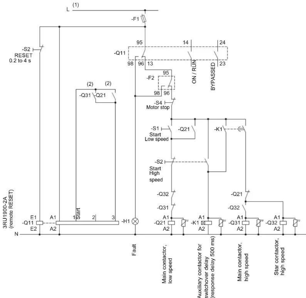
flowchart
graph TD
    A["3RU1900-2A (remote RESET)"] --> B["(-Q11 E1, -Q21 A1, -Q31 Start, -Q12 Start Low speed"]
    B --> C["(-Q11 Q21, -Q31 Start, -Q21 High speed)"]
    C --> D["(-Q11 F1, -Q21 K1, -Q31 Start High speed)"]
    D --> E["(-Q11 ON / RUN, BYPASSED, -S4 Motor stop)"]
    E --> F["(-Q21 Start Low speed, -S1 Motor stop)"]
    F --> G["(-Q21 Start High speed, -S2 Motor stop)"]
    G --> H["(-Q21 Start Low speed, -K1 Motor stop)"]
    H --> I["(-Q21 Start High speed, -Q32 Motor stop)"]
    I --> J["(-Q21 Start Low speed, -K1 Motor stop)"]
    J --> K["(-Q21 Start High speed, -Q32 Motor stop)"]
    K --> L["(-Q21 Start Low speed, -K1 Motor stop)"]
    L --> M["(-Q21 Start High speed, -Q32 Motor stop)"]
    M --> N["(-Q21 Start Low speed, -K1 Motor stop)"]
    N --> O["(-Q21 Start High speed, -Q32 Motor stop)"]
    O --> P["(-Q21 Start Low speed, -K1 Motor stop)"]
    P --> Q["(-Q21 Start High speed, -Q32 Motor stop)"]
    Q --> R["(-Q21 Start Low speed, -K1 Motor stop)"]
    R --> S["(-Q21 Start High speed, -Q32 Motor stop)"]
    S --> T["(-Q21 Start Low speed, -K1 Motor stop)"]
    T --> U["(-Q21 Start High speed, -Q32 Motor stop)"]
    U --> V["(-Q21 Start Low speed, -K1 Motor stop)"]
    V --> W["(-Q21 Start High speed, -Q32 Motor stop)"]
    W --> X["(-Q21 Start Low speed, -K1 Motor stop)"]
    X --> Y["(-Q21 Start High speed, -Q32 Motor stop)"]
    Y --> Z["(-Q21 Start Low speed, -K1 Motor stop"]
Figure 15-34 Wiring of the 3RW40 5 to 3RW40 7 control circuit
15.11 Dahlander / multispeed motor
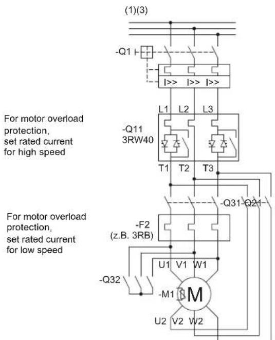
Figure 15-35 Wiring of the 3RW40 5 to 3RW40 7 main circuit
(1) For the permissible values for the main and control voltage (dependent on the MLFB), refer to chapter Technical data [Page 121].

WARNING
(2) Automatic restart.
Can result in death, serious injury, or property damage.
The start command (e.g. issued by the PLC or switch S1) must be reset prior to issuing a RESET command because the motor attempts to restart again automatically following this RESET command if a start command is still present. This particularly applies if the motor protection has tripped. For safety reasons, you are advised to integrate the group fault output (terminals 95 and 96) in the controller.
(3) Alternatively, the motor feeder can be assembled as a fuseless or fused version with type of coordination 1 or 2. For the assignment of fuses and switching devices, refer to chapter technical data [Page 121]
NOTICE
No soft stop possible. Set the ramp-down time to 0 s with the potentiometer.
16.1 Box terminal blocks for soft starters
| For soft starter type Size Version Order No. | |||
| Box terminal blocks for soft starters for round and ribbon cables | |||
 | 3RW40 5. S6 | Max. 70 mm ^2 | 3RT19 55-4G |
| Max. 120 mm ^2 | 3RT19 56-4G | ||
| 3RW40 7. S12 | Max. 240 mm ^2 | 3RT19 66-4G | |
16.2 Auxiliary conductor terminals
| For soft starter type Size Order No. | |
| Auxiliary conductor terminals, 3-pole | |
| 3RW30 4. | S3 3RT19 46-4F |
| 3RW40 4. | |
16.3 Covers for soft starters
| For soft starter type Size Order No. | ||
| Terminal covers for box terminals | ||
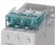 | Additional touch protection to be fitted at the box terminals (2 units required per device) | |
| 3RW30 3. | S2 3RT19 36-4EA2 | |
| 3RW40 3. | ||
| 3RW30 4. | S3 3RT19 46-4EA2 | |
| 3RW40 4. | ||
| 3RW40 5. S6 3RT19 56-4EA2 | ||
| 3RW40 7. S12 3RT19 66-4EA2 | ||
| Terminal covers for cable lug and busbar connections | ||
 | For complying with the phase clearances and as touch protection if box terminal is removed (2 units required per contactor) | |
| 3RW30 4. | S3 3RT19 46-4EA1 | |
| 3RW40 4. | ||
| 3RW40 5. S6 3RT19 56-4EA1 | ||
| 3RW40 7. S12 3RT19 66-4EA1 | ||
16.4 Modules for RESET
| For soft starter type Size Order No. | |||
| Sealing covers | |||
 | 3RW40 2 to 3RW40 4. S0, S2, S3 3RW49 00-0PB10 | ||
| 3RW40 5. and | S6 | 3RW49 00-0PB00 | |
| 3RW40 7 | S12 | ||
16.4 Modules for RESET
| For soft starter type Size Version Order No. | ||||
| Modules for remote RESET, electrical | ||||
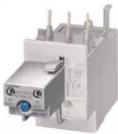 | Operating range 0.85 to 1.1 x Us,Power consumption AC 80 VA, DC 70 W,ON time 0.2 s to 4 s,Switching frequency 60/h | |||
| 3RW40 5. and3RW40 7. | S6,S12 | • AC/DC 24 V ... 30 V 3RU19 00-2AB71 | ||
| • AC/DC 110 V ... 127 V | 3RU19 00-2AF71 | |||
| • AC/DC 220 V ... 250 V | 3RU19 00-2AM71 | |||
| Mechanical RESET, comprising | ||||
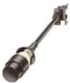 | 3RW40 5. and3RW40 7. | S6,S12 | • Resetting plunger, holder, and former | 3RU19 00-1A |
| • Suitable pushbutton IP65, 22 mm diameter,12 mm stroke | 3SB30 00-0EA11 | |||
| • Extension plunger | 3SX13 35 | |||
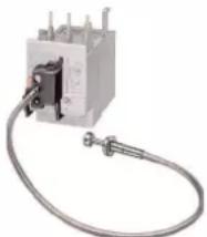
natural_image
Electrical contactor device with coiled cable and terminal ports (no visible text or symbols)Note
Remote RESET is already integrated in the 3RW40 2. to 3RW40 4. soft starters.
16.5 Link modules to 3RV10 motor starter protectors
| For soft starter type Size | Motor starter protector size | Order No. | ||
| Link modules to 3RV10 motor starter protectors | ||||
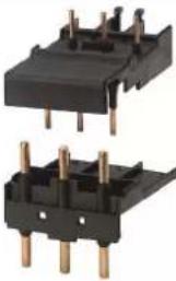 | 3RW30 13,3RW30 14,3RW30 16,3RW30 17,3RW30 18 | S00 S0 3RA19 21-1A | ||
| 3RW30 26 | S0 S0 3RA19 21-1A | |||
| 3RW40 24 | ||||
| 3RW40 26 | ||||
| 3RW30 36 | S2 S2 3RA19 31-1A | |||
| 3RW40 36 | ||||
| 3RW30 46,3RW30 47 | S3 S3 3RA19 41-1A | |||
| 3RW40 46,3RW40 47 | ||||
16.6 Link modules to 3RV20 motor starter protectors
| For soft starter type Size | Motor starter protector size | Order No. | |
| Link modules to 3RV20 motor starter protectors1) | |||
 | With screw terminals | ||
| 3RW30 1. S00 S00 3RA29 21-1BA00 | |||
| 3RW30 2. S0 S0 3RA29 21-1BA00 | |||
| 3RW40 2. S0 S0 3RA29 21-1BA00 | |||
| With spring-loaded terminals | |||
| 3RW30 1. S00 S00 3RA29 11-2GA00 | |||
| 3RW30 2. S0 S0 3RA29 21-2GA00 | |||
| 3RW40 2 S0 S0 3RA29 21-2GA00 | |||
1) Size S0 can be used up to 32 A.
16.7 Optional fan to increase the switching frequency (3RW40 2. to 3RW40 4.).
16.7 Optional fan to increase the switching frequency (3RW40 2. to 3RW40 4.).
| For soft starter type Size Order No. | |||
| Fan (to increase the switching frequency and for device mounting in positions different from the normal position) | |||
| 3RW40 2. S0 3RW49 28-8VB00 | |||
 | 3RW40 3., | S2, | 3RW49 47-8VB00 |
| 3RW40 4 | S3 | ||
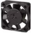 | |||
16.8 Spare parts for fans (3RW40 5., 3RW40 7.)
| For soft starter type Size | VersionRated control supply voltage Us | Order No. | |
 | 3RW40 5.-BB3. S6 115 V AC 3RW49 36-8VX30 | ||
| 3RW40 5.-BB4. S6 230 V AC 3RW49 36-8VX40 | |||
| 3RW40 7.-BB3. S12 | 115 V AC 3RW47 36-8VX30 | ||
| 3RW40 7.-BB4. S12 | 230 V AC 3RW47 36-8VX40 | ||
16.9 Operating instructions
| For soft starter type | Size | Order No. |
| Operating instructions for soft starters | ||
| 3RW30 1. to 3RW30 4. | S00 to S3 | 3ZX10 12-0RW30-2DA1 |
| 3RW40 2. to 3RW40 4. | S0 to S3 | 3ZX10 12-0RW40-1AA1 |
| 3RW40 5., 3RW40 7. | S6 , S12 | 3ZX10 12-0RW40-2DA1 |
Note
The operating instructions are included in the scope of supply.
A.1 Configuration data
Configuration data
Siemens AG
Technical Support Low-Voltage Control Systems
Phone: +49 (0) 911-895-5900
Fax: +49 (0) 911-895-5907
e-mail: technical-assistance@siemens.com
- Motor data
Siemens motor?
Rated output: kW
Rated voltage: V
Mains frequency: Hz
Rated current: A
Starting current: A
Rated speed: rpm
Rated torque: Nm
Breakdown torque: Nm
Mass moment of inertia: kg*m2
Speed / torque characteristic curve
(The speed increments of the value pairs do not have to be equal)
| n_M 1/m "n | syn" | |||||||||||
| M_M/M_B |
Speed / current characteristic curve
(The speed increments of the value pairs do not have to be equal)
| n_M 1/m | " n_syn " | |||||
| I_M/I_B |
A.1 Configuration data
1. Load data
Load type (e.g. pump, mill etc.):
Rated speed: rpm
Rated torque or rated output Nm or kW
Mass moment of inertia (load-specific)
Mass moment of inertia (motor-specific)
kg*m²
kg*m²
Speed / torque characteristic curve
(The speed increments of the value pairs do not have to be equal)
| n_L 1/m "n | syn" | |||||||||||
| M_L/M_B |
1. Start conditions
Starting frequency Starts
Switching
Rampup time
cycles:
Operating time
Idle time
Ramp-down time
Ambient temperature °C
Yes Value
Starting current limitation? ......
Acceleration torque limitation?
Maximum ramp-up time?
1. Personal details
Last name, first name:
Company:
Department:
Street:
Zip code, town/city:
Country:
Phone:
Fax:
e-mail:
A.2 Table of parameters used
You can document your parameter settings in the table below.
| 3RW40 parameters | ||||||||||
| X | ||||||||||
| X | ||||||||||
| Manual (off) | ||||||||||
CLASS value  | 10 | |||||||||
| CLASS |  |  |  |  | ||||||
 |  |  |  |  | ||||||
| x1 | ||||||||||
| t ramp-down s |  |  |  |  | ||||||
| e | ||||||||||
 |  |  |  |  | ||||||
 |  |  |  | [BY73] | ||||||
| Parameters 3RW30 or 3RW40 | t ramp-up s | 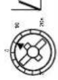 |  |  |  |  |  |  |  | |
| U starting % | [SDZT] |  |  | |||||||
| Plant Identifier | 3RW4038-1TB04 | 3RW4038-1TB04 |  |  |  |  |  |  | ||
A.3 Correction sheet
A.3 Correction sheet
TO FROM (please
complete):
SIEMENS AG Name
A&D CD MM3
92220 Amberg / Germany
Company / Department
Address
Phone
Fax: 0 96 21 / 80-33 37 Fax
System Manual for SIRIUS 3RW30 / 3RW40 soft starters
Have you noticed any errors while reading this manual?
If so, please use this form to tell us about them.
We welcome comments and suggestions for improvement.
Index
Numerics
3RW44 15, 28, 95
3RW44 soft starter 15, 28, 95
A
Accessories 199
Ambient temperature 80
Application examples 76
Heavy-duty starting 78
Normal starting 77
Applications 22
For current limiting 30
Soft stop 32
Assembly type 81, 84
ATEX 33, 134
B
Bypass contacts 96, 104, 109
Bypass mode 19
BYPASSED function 42
C
Capacitors 62
CLASS 10 76, 77, 107
CLASS 15 107
CLASS 20 78, 107
CLASS potentiometer 106
CLASS setting 33, 34, 106
Commissioning 92, 99
Configuration 73
Configurator 86
Contact 57
Current limiting 24, 27, 29, 30, 103, 104
Current limiting value 29, 104
D
Degree of protection 56
Device combinations 25
Diagnostics 44, 47, 97, 118
Direct mounting 56
Disconnector 57
Documentation of parameters 205
Documentation of settings 205
F
Fan 53
Fault signals 37, 39, 45, 47, 60, 97, 118
Five safety rules for electricians 13, 58
Full motor protection 33
H
Heavy-duty starting 62, 78
Ambient temperature 78
General conditions and constraints 78
Installation altitude 78
ON time 78
Parameter settings 78
|
le potentiometer 106
Increased safety 33, 134
Installation altitude 80
CLASS 10 77
CLASS 20 78
Normal starting 77
Intrinsic device protection 35
M
Maximum ramp-up time 77, 78
Method of operation
Soft starters 19
Two-phase control 20
Motor current settings 107
Motor overload protection 33
Motor protection function 32
Motor ramp-up detection 104
Motor ramp-up time 95
Mounting position 81, 84.
Horizontal 53
Vertical 53, 80
N
Natural stop 31
Normal starting 73, 77, 122, 136, 138, 140, 142, 144
Ambient temperature 77
General conditions and constraints 77
Installation altitude 77
ON time 77
Parameter settings 77
0
ON function 42, 109
ON time 79
Heavy-duty starting 78
Normal starting 77
Online configurator 86
Output contact 96, 109
Overload protection 34
P
Phase angle control 20
Polarity balancing 20, 21
PROFIBUS 15
Protection against voltage failure 35
PTC thermistors 35
Pump stop 31
R
Ramp time 27, 94, 95, 102
Ramp-down time 31, 105
Ramp-up 104
Ramp-up detection 28, 30, 76
Ramp-up time 95
3RW30 95
3RW40 102
ramp-up time
Maximum 77, 78
Rated data
Reduction 80
Rated operational current 106
Recovery time
Intrinsic device protection 35
Motor overload protection 34
Thermistor motor protection 35
Reduced starting current 17
RESET MODE 115
RUN function 42, 109
s
Safety rules 13, 58
Screw-type technology 65
Selection criteria 22
Semiconductor fuses 36
Side-by-side assembly 55
SIRIUS 3RW44 soft starter 15, 28, 95
SIRIUS modular system 25
SITOR 36
SITOR semiconductor fuses 36
Soft start 19, 94, 101
Soft stop 19, 105
Spring-loaded technology 65
Standalone assembly 55
Start 19
Start modes 73
Starting current 16
Starting current asymmetry 29, 104
Starting torque 16, 27
Starting voltage 27
Startup class 76
Stop 19
Stop modes 30
Stop without load 31, 105
Stopping torque 31
Switching frequency 79, 85
T
t potentiometer 102, 105
Technical Assistance 12
Temperature sensor 35
Thermistor motor protection 33, 35, 108, 134, 167
Thermoclick sensors 35
Three-phase induction motor 15, 18
Thyristor 19, 20
Thyristor protection 36
Trip class 33, 34, 106
Troubleshooting 44, 47, 97, 118
Two-phase control 20
Two-phase soft starters 20
Type of coordination 36, 59, 60, 61, 62, 128
1 128, 155
2 128, 155
U
Ultra-heavy-duty starting 15
v
Voltage ramp 27, 29, 94, 101, 102
W
Water hammer 31
Win-Soft Starter 86
Win-Soft Starter software 86
X
xle potentiometer 104
Service & Support
Download catalogs and information material: www.siemens.com/lowvoltage/catalogs
Newsletter – always up to date: www.siemens.com/lowvoltage/newsletter
E-business in the Industry Mall: www.siemens.com/lowvoltage/mall
Online-Support: www.siemens.com/lowvoltage/support
Contact for all technical information:
Technical Assistance
Tel.: +49 (911) 895-5900
e-mail: technical-assistance@siemens.com
www.siemens.com/lowvoltage/technical-assistance
Siemens AG
Industry Sector
Postfach 48 48
90026 NÜRNBERG
GERMANY
Subject to change without prior notice
Order No.: 3ZX1012-0RW30-1AC1
© Siemens AG 2010

- Industrial Controls
- SIEMENS
- Soft starters SIRIUS 3RW30 / 3RW40
- Manual
- Legal information
- Warning notice system
- Qualified Personnel
- Proper use of Siemens products
- Trademarks
- Disclaimer of Liability
- Table of contents
- Introduction 11
- Safety information 13
- Product description 15
- Product combinations 25
- Functions 27
- Application planning 51
- Installation 53
- Installation / mounting 57
- Connecting 65
- Operation 69
- Configuration 73
- Commissioning 91
- Technical data 121
- Dimension drawings 163
- Typical circuit diagrams 167
- Accessories 199
- A Appendix 203
- Introduction
- Important notes
- Purpose of the manual
- Target group
- Basic knowledge required
- Scope of validity
- Standards and approvals
- Orientation aids
- Continuously updated information
- Correction sheet
- Before commencing work: Isolating the equipment from the supply system and ensuring that it cannot be reconnected.
- DANGER
- Hazardous voltage Will cause death or serious injury.
- Qualified Personnel.
- Five safety rules for work in or on electrical systems
- Explanations
- Product description
- Fields of application
- SIRIUS soft starter family
- 3RW30 and 3RW40
- 3RW44
- Basic physical principles of a three-phase induction motor
- Three-phase induction motor
- Fields of application
- Problem
- Starting current
- Disadvantage
- Starting torque
- Disadvantages
- Remedy
- Functional principle of the SIRIUS 3RW30 and 3RW40 soft starters
- Example
- Soft start /soft stop
- Bypass mode
- Method of operation of a two-phase controlled soft starter
- Two-phase control
- Polarity balancing
- Starting current asymmetry
- Note
- Applications and use
- Applications and selection criteria
- Applications
- Advantages
- Comparison of device functions
- SIRIUS modular system
- Switching, protecting, and starting motors
- Functions
- Start modes
- Voltage ramp
- Starting voltage
- Ramp time
- CAUTION
- Risk of property damage
- Typical applications of the voltage ramp
- Current limiting and ramp-up detection (3RW40 only)
- Current limiting value
- Stop modes
- Ramp-up detection (3RW40 only)
- Typical applications for current limiting
- Stop without load (3RW30 and 3RW40)
- Typical applications for stop without load
- Soft stop (3RW40 only)
- Ramp-down time
- Motor protection / intrinsic device protection (3RW40 only)
- Typical applications for soft stop
- NOTICE
- Motor protection function
- Thermistor motor protection evaluation
- Motor overload protection
- ATEX
- "Increased safety" type of protection EEx e acc. to ATEX Directive 94/9/EC
- WARNING
- Danger of death or serious injury.
- Trip class (electronic overload protection)
- Recovery time (motor overload protection)
- Protection against voltage failure in the event of a fault
- Temperature sensor
- Recovery time (thermistor motor protection)
- Intrinsic device protection (3RW40 only)
- Thyristor protection (thermal)
- Recovery time (intrinsic device protection)
- Functions of the RESET buttons
- Thyristor protection (short-circuit)
- Protection against voltage failure (in the event of a fault)
- SIRIUS 3RW40 2, 3RW40 3, and 3RW40 4 soft starters
- RESET MODE button and LED
- Manual RESET
- Remote RESET
- AUTO RESET
- Automatic restart
- Acknowledging faults
- SIRIUS 3RW40 5 and 3RW40 7 soft starters
- RESET MODE button and AUTO LED
- Manual RESET
- Remote RESET
- AUTO RESET
- AUTO RESET (AUTO LED = yellow)
- Acknowledging faults
- Other functions of the RESET button
- Motor protection trip test
- Reparameterizing the ON / RUN output contact
- Functions of the inputs
- Start input (terminal 1) on 3RW30 and 3RW40 2 to 3RW40 4
- Start input (terminal 3) on 3RW40 5 and 3RW40 7
- Thermistor input / connection on 3RW40 2 to 3RW40 4
- Functions of the outputs
- 3RW30: Output terminal 13 / 14 ON
- 3RW40: Output terminals 13 / 14 ON / RUN and 23 / 24 BYPASSED
- ON
- Reparameterizing from ON to RUN
- RUN
- BYPASSED
- 3RW40: Group fault output at terminal 95 / 96 / 98 OVERLOAD / FAILURE
- Diagnostics and fault signals
- 3RW30: LEDs and troubleshooting
- Can result in death, serious injury, or property damage.
- Application planning
- Application examples
- Roller conveyor application
- Using the 3RW30 with roller conveyors
- Hydraulic pump application
- Using the 3RW40 with hydraulic pumps
- Installing the soft starter
- Unpacking
- Permissible mounting position
- Mounting dimensions, clearances, and assembly type
- Assembly type: Standalone assembly, side-by-side assembly, direct mounting
- Standalone assembly
- Side-by-side assembly
- Direct mounting
- Installation requirements
- Degree of protection IP00
- General information
- General information
- Disconnector
- Contact
- Hazardous voltage
- Five safety rules for work in or on electrical systems
- General feeder assembly (type of coordination 1)
- Soft starter with line contactor (type of coordination 1)
- Soft starter assembly with type of coordination 2
- Capacitors to improve the power factor
- Minimum and maximum configuration of the semiconductor fuses
- Maximum cable length
- Connecting
- Electrical connection
- Control and auxiliary terminals
- Main circuit connection
- Sizes 3RW40 5. and 3RW40 7.
- Operator controls, displays, and connections on the 3RW30
- Operator controls, displays, and connections on the 3RW40
- Configuration in general
- Configuration procedure
- Selecting the optimum soft starter
- Selection aid
- SIRIUS 3RW44 soft starter
- Startup class
- Selection criteria
- Application examples for normal starting (CLASS 10) with 3RW30 and 3RW40
- Recommended basic parameter settings
- Application examples for heavy-duty starting (CLASS 20): 3RW40 only
- ON time and switching frequency
- ON time
- Switching frequency
- Optional additional fan
- Reducing the rated data
- Installation altitude and ambient temperature
- Installation altitude
- Ambient temperature
- Calculating the permissible switching frequency
- Risk of property damage.
- Mounting position, assembly type
- Table of permissible assembly combinations with switching frequency factors
- Calculating the switching frequency (example)
- Calculating the number of starts / hour of a 3RW40 for side-by-side assembly and vertical mounting
- Result
- Configuration aids
- Online configurator
- Win-Soft Starter selection and simulation software
- Technical Assistance
- SIRIUS soft starter training course (SD-SIRIUSO)
- Order number system for the 3RW30
- Order number system for the 3RW40
- Before commencing work: Isolating the equipment from the supply system and ensuring that it cannot be reconnected.
- Commissioning the 3RW30
- Commissioning procedure
- Quick commissioning of the 3RW30 and optimization of the parameters
- Setting the soft start function
- Voltage ramp
- Setting the starting voltage
- U potentiometer
- Setting the ramp time
- t potentiometer
- ON output
- ON output contact
- 3RW30: LEDs and troubleshooting
- Commissioning the 3RW40
- Commissioning procedure
- Quick commissioning of the 3RW40 and optimization of the parameters
- Setting the soft start function
- Setting the starting voltage
- Setting the ramp time
- Current limiting in conjunction with a starting voltage ramp and ramp-up detection
- Setting the motor current
- Setting the current limiting value
- xl_e potentiometer
- Ramp-up detection
- Setting the soft stop function
- Setting the ramp-down time
- Setting the motor protection function
- Setting the electronic motor overload protection
- I_e potentiometer
- CLASS potentiometer
- Motor current settings
- Motor protection acc. to ATEX
- Thermistor motor protection
- Thermistor motor protection
- Motor protection trip test
- TEST / RESET button
- Functions of the outputs
- Functions of the BYPASSED and ON / RUN outputs
- BYPASSED output contact
- ON / RUN output contact
- Reparameterizing the output of the ON function (factory default) to RUN
- Parameterizing the 3RW40 outputs
- Reparameterizing the ON / RUN output
- Function of the FAILURE / OVERLOAD output
- FAILURE / OVERLOAD output contact
- RESET MODE and functions of the RESET / TEST button
- SIRIUS 3RW40 2. to 3RW40 4. soft starters
- Setting the RESET MODE
- RESET MODE button
- Manual RESET
- RESET / TEST button (RESET MODE LED off)
- Remote RESET
- AUTO RESET
- SIRIUS 3RW40 5. to 3RW40 7. soft starters
- Setting the RESET MODE
- Manual RESET
- RESET / TEST button (AUTO LED off)
- Remote RESET
- Remote RESET with module for RESET (AUTO LED = off)
- AUTO RESET
- Technical data
- 3RW30
- Overview
- Selection and ordering data for standard applications and normal starting
- 3RW30..-BB.. power electronics
- 3RW30 13, 14, 16, 17, 18-.BB.. power electronics
- 3RW30 main conductor cross-sections
- 3RW30 auxiliary conductor cross-sections
- Electromagnetic compatibility according to EN 60947-4-2
- Recommended filters
- Types of coordination
- Types of coordination
- Fuseless version
- Fused version (line protection only)
- Fused version with SITOR 3NE1 fuses
- Fused version with SITOR 3NE3/4/8 fuses
- 3RW40
- Overview
- "Increased safety" type of protection EEx e according to ATEX Directive 94/9/EC
- Selection and ordering data for standard applications and normal starting (CLASS 10)
- Selection and ordering data for standard applications and normal starting (CLASS 10) (with thermistor motor protection evaluation)
- Selection and ordering data for standard applications and normal starting (CLASS 10)
- Selection and ordering data for standard applications and heavy-duty starting (CLASS 20)
- Selection and ordering data for standard applications and heavy-duty starting (CLASS 20)
- 3RW40 2., 3., 4. control electronics
- 3RW40 5., 7. control electronics
- 3RW40 24, 26, 27, 28 power electronics
- 3RW40 .. auxiliary conductor cross-sections
- Electromagnetic compatibility according to EN 60947-4-2
- Recommended filters
- Types of coordination
- Fuseless version
- Fused version (line protection only)
- Fused version with SITOR 3NE1 fuses
- Fused version with SITOR 3NE3/4/8 fuses
- Win-Soft Starter selection and simulation software
- 3RW30 for standard applications
- 3RW40 for standard applications
- Typical circuit for the optional thermistor motor protection evaluation
- Control by pushbutton
- Control of the 3RW30 by pushbutton
- Control of the 3RW40 by pushbutton
- Control by switch
- Control of the 3RW30 by switch
- Control of the 3RW40 by switch
- Automatic restart.
- Control in automatic mode
- Automatic restart. Can result in death, serious injury, or property damage.
- Control of the 3RW40 in automatic mode
- Idle time until restart.
- Control by PLC
- Control of the 3RW30 with 24 V DC by PLC
- Control of the 3RW40 by PLC
- Control with an optional main / line contactor
- Control of the 3RW30 with a main contactor
- Control of the 3RW40 with a main contactor
- Reversing circuit
- 3RW30 reversing circuit
- Control of a magnetic parking brake
- 3RW30 motor with magnetic parking brake
- 3RW40 2 to 3RW40 4, control of a motor with a magnetic parking brake
- 3RW40 5 to 3RW40 7, control of a motor with a magnetic parking brake
- Emergency stop
- 3RW30 emergency stop and 3TK2823 safety relay
- 3RW40 2 to 3RW40 4 emergency stop and 3TK2823 safety relay
- 3RW40 5 to 3RW40 7 emergency stop and 3TK2823 safety relay
- 3RW and contactor for emergency starting
- 3RW30 and contactor for emergency starting
- 3RW40 and contactor for emergency starting
- Dahlander / multispeed motor
- 3RW30 and Dahlander motor starting
- Box terminal blocks for soft starters
- Auxiliary conductor terminals
- Covers for soft starters
- Modules for RESET
- Link modules to 3RV10 motor starter protectors
- Link modules to 3RV20 motor starter protectors
- Optional fan to increase the switching frequency (3RW40 2. to 3RW40 4.).
- Spare parts for fans (3RW40 5., 3RW40 7.)
- Operating instructions
- A.1 Configuration data
- Configuration data
- Load data
- Start conditions
- Personal details
- A.2 Table of parameters used
- A.3 Correction sheet
- System Manual for SIRIUS 3RW30 / 3RW40 soft starters
- Index
- Numerics
- A
- B
- C
- D
- F
- H
- |
- M
- N
- 0
- P
- R
- s
- T
- U
- v
- W
- X
- Service & Support
Brand : SIEMENS
Model : 3RW4027-1BB15
Category : Uncategorized