
MGK-2-470 - Central heating boiler WOLF - Free user manual and instructions
Find the device manual for free MGK-2-470 WOLF in PDF.


| Product Type | Central Heating Boiler |
| Brand | Wolf |
| Model | MGK-2-470 |
| Fuel Type | Natural Gas |
| Heating Output | 24 kW |
| Efficiency | 90% (condensing) |
| Dimensions (H x W x D) | 800 x 600 x 400 mm |
| Weight | 80 kg |
| Power Supply | 230 V, 50 Hz |
| Control System | Electronic with LCD display |
| Safety Features | Overheat protection, frost protection, flame failure device |
| Flue Type | Room-sealed (concentric) |
| Water Pressure Range | 1.0 - 2.0 bar |
| Max Flow Temperature | 80°C |
| Expansion Vessel Capacity | 8 L |
| Maintenance Frequency | Annual service by qualified engineer |
| Cleaning Instructions | Wipe casing with damp cloth; clean flue yearly |
| Spare Parts Availability | Available through Wolf service centers |
| Reparability Index | 7.5 / 10 |
| Protection Class | IPX4 |
| Energy Class | A (ErP directive) |
| Warranty | 2 years standard |
Frequently Asked Questions - MGK-2-470 WOLF
User questions about MGK-2-470 WOLF
0 question about this device. Answer the ones you know or ask your own.
Ask a new question about this device
Download the instructions for your Central heating boiler in PDF format for free! Find your manual MGK-2-470 - WOLF and take your electronic device back in hand. On this page are published all the documents necessary for the use of your device. MGK-2-470 by WOLF.
USER MANUAL MGK-2-470 WOLF
Installation instructions for contractors
Gas condensing boilers

natural_image
Landscape photo of two people relaxing on a grassy hill with a large tree and sky in the background (no text or symbols visible)MGK-2-390 MGK-2-470 MGK-2-550 MGK-2-630

natural_image
Exterior view of a white industrial machine with black control knobs and a digital display (no visible text or symbols)- Information about this document....3
- Safety instructions....4 - 5
- Dimensions 6
- Specification....8
- Boiler layout 9
- Casing....10
- Standards and regulations 11 - 12
Installation
- Handling / Installation instructions....13 - 15
-
Safety equipment....16
-
Information about water treatment.... 17
-
Boiler system pipework.... 18
-
Selection of circulation pumps.... 19
-
Gas connection.... 20
-
Fitting the siphons 21
-
Neutralising system (accessory).... 22
-
Neutralising system / Condensate pump (accessories) 23
-
Air/flue gas routing....24 - 25
Control unit
-
Electrical connection....26 - 31
-
Display/programming module / Installation.... 32
-
AM display module 32
- AM display module menu structure 34
- Operating mode / Heating appliance burner status....35
- BM2 programming module 36
- HG control parameters 37
- Parameter description 38 - 47
- Flue gas damper power supply 48
Cascade operation
- Cascade operation 49 - 51
Commissioning
- Filling / draining the heating system 52
- Commissioning....53
- Checking the gas supply pressure 54
- Changing the gas type / CO _2 settings....55 - 56
Specification
- Commissioning report....57
- Design information – air/flue gas routing....58
- Wiring diagram HCM2 /GBC-P 59 - 60
- Troubleshooting....61 - 64
- Troubleshooting warning messages....65
-
Sensor resistance table....66
-
Technical parameters according to EU regulation no. 813/2013......67
Declaration of conformity 68
1. Information about this document
1.1 Other applicable documents
MGK-2 user operating instructions
MGK-2 maintenance instructions
System and operator's log
The instructions for all accessory modules and other accessories may also apply.
1.2 Safekeeping of these documents
The system user or operator should ensure the safekeeping of all instruction manuals and documents.
▶ Please pass these installation instructions and all other applicable instruction manuals on to the operator and/or system user.
1.3 Obligations of the operator
System operators must take active steps to fulfil their responsibilities regarding safe gas use. This applies to the commissioning of specialist companies to maintain the appliance. The system operator is obliged to provide documentation.
1.4 Applicability of these instructions
These installation instructions apply to the MGK-2 gas condensing boiler
1.5 Acceptance
Within four weeks of commissioning of the burner the operator must notify the local flue gas inspector accordingly.
1.6 Information about disposal
We are happy to accept the return of your old Wolf boiler free of charge at one of our delivery depots.
MGK-2 standard delivery
1 x MGK-2 gas condensing boiler, fully encased, assembled and wired
2 x siphons with 3 condensate hoses and 1 tee
1 x condensate trap
1 x MGK-2 installation instructions for contractors
1 x MGK-2 user operating instructions
1 x MGK-2 maintenance instructions
1 x system and operator's log
2. Safety instructions
Authorised personnel should read these instructions before any installation, commissioning or maintenance work. Observe the instructions given in this document. Failure to observe these installation instructions voids any WOLF warranty. In some countries, the installation of a gas boiler must be notified to and approved by the relevant gas supply company. Please note that regional permits may be required for the flue system and the condensate drain into the public sewer. Before installation work begins, the local flue gas inspector and water authority must be informed. The boiler must be installed, commissioned and maintained by qualified and trained personnel only. In accordance with VDE 0105 Part 1, work on electrical components (e.g. control unit) must only be carried out by qualified electricians. VDE/ÖVE regulations and those of your local power supply utility company are applicable to electrical installation work. Only operate the boiler within its output range, which is stated in the technical documentation supplied by WOLF. Intended use of the boiler refers to the exclusive use for hot water heating systems in accordance with DIN EN 12828. Never remove, bypass or otherwise disable any safety and monitoring equipment. The boiler must only be operated if it is in perfect technical condition. Any faults and damage with potential impact on safety and which might limit the safe use of the equipment must be remedied immediately by a qualified contractor. Only replace faulty components and equipment with original WOLF spare parts.
The following symbols are used in these instructions. This important information concerns personal as well as operational safety.

"Safety instructions" are instructions with which you must comply exactly, to prevent risks and injuries to individuals and damage to the boiler.

Danger due to live electrical components.
Please note: Turn OFF the ON/OFF switch before removing the casing.
Never touch electrical components or contacts when the ON/OFF switch is in the ON position. This can result in a risk of electrocution that could lead to injury or death.
The terminals are live even when the ON/OFF switch is in the OFF position.

"Caution" indicates technical instructions that you must observe to prevent boiler damage and malfunctions.
Working on the system
- Gas systems: close the gas shut-off valve and ensure that unauthorised reopening is prevented.
- Isolate the system from the power supply (e.g. by removing a separate mains fuse or by means of a mains electrical isolator, heating emergency stop switch) and check to ensure that there is no voltage.
- Safeguard the system against restarting.
Danger if you smell gas
- Close the gas shut-off valve.
- Open the windows.
- Do not operate electrical switches.
- Extinguish naked flames.
- Phone the gas supply utility company and approved contractor from an external location.
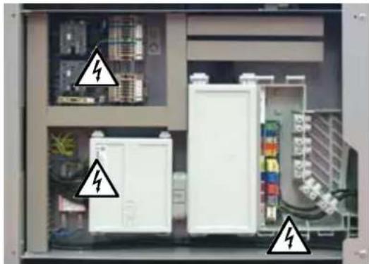
natural_image
Interior view of an electrical enclosure with white electronic components and black warning symbols (no readable text or labels)Fig: Control box
Danger from electrical voltage
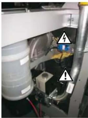
natural_image
Interior view of a mechanical or electrical device with visible wiring and warning symbols (no readable text or labels)Fig: Ignition transformer, high voltage ignition electrode, gas combination valve, gas pressure switch, fan, combustion chamber.
Danger from electrical voltage, escaping gas may cause poisoning or an explosion, risk of burning through hot components.
Danger if you smell flue gas
- Switch OFF the boiler.
- Open windows and doors.
- Notify an approved contractor.
Inspection and maintenance
- Recommendation for the customer: Take out an inspection and maintenance contract with an approved contractor, including an annual inspection and demand-dependent servicing.
- The operator is responsible for the safety, environmental compatibility and energy quality of the heating system (German Immission Control Act / Energy Saving Ordinance).
- Only use genuine spare parts!

We accept no liability for damage caused by technical modifications made to the control unit or the control system components.
Note
These installation instructions must be kept in a safe place and read before installing the boiler. Please also observe the design information in the appendix.
Information about disposal:
We are happy to accept the return of your old Wolf boiler free of charge at one of our delivery depots.
This appliance is not designed to be operated by persons (including children) with restricted physical, sensory or mental capacities or who lack the necessary experience and/or knowledge, unless they are supervised by a person responsible for their safety or have received instructions on how to use the appliance from this person.
3. Dimensions
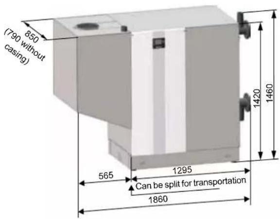
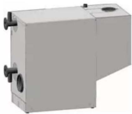
natural_image
3D rendering of a gray industrial or laboratory equipment unit with two side ports and a central circular opening (no text or symbols visible)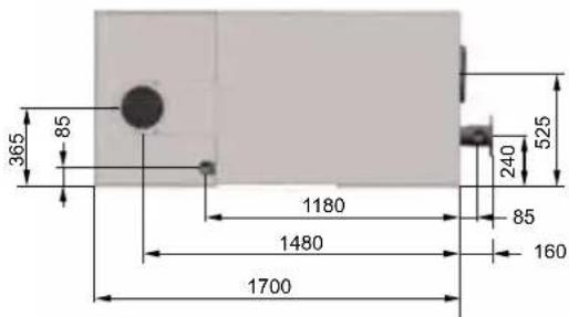

natural_image
Simple diagram of a device with labeled points A and B, no text or symbols present
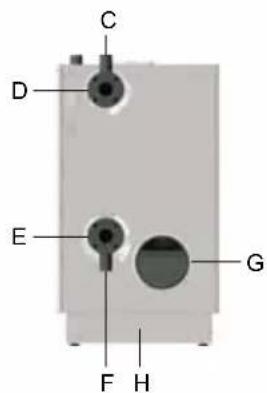
A = ventilation air pipe DN 200
B = gas pipe 2"
C = safety assembly connection 2"
D = flow pipe DN 80
E = return pipe DN 80
F = BDF valve connection
G = flue pipe DN 250
H = condensate drain
| Type MGK-2 390 470 550 630 | |||||
| Rated heating output at 80/60 °C kW 366.7 434.7 511.6 584.4 | |||||
| Rated heating output at 50/30 °C kW 392.0 467.1 549.3 626.6 | |||||
| Rated heat input kW 371.2 443.6 521.0 593.9 | |||||
| Low boiler output (modul.) at 80/60 °C kW 58.5 70.7 84.5 96.7 | |||||
| Low boiler output (modul.) at 50/30 °C kW 64.2 78.7 94.0 106.8 | |||||
| Low heat input (modulating) kW 59.5 73.2 86.8 98.5 | |||||
| Heat input modulation range | % | 17-100 | 17-100 | 17-100 | 17-100 |
| Efficiency η 80/60 at Qmax | % | 98.8 | 98.0 | 98.2 | 98.4 |
| η 50/30 at Qmax | % | 105.6 | 105.3 | 105.4 | 105.5 |
| η TR30 at 30 % | % | 107.8 | 108.9 | 108.6 | 107.6 |
| Standard seasonal efficiency at 40/30 °C | % | 109.9 | 110.1 | 110.3 | 110.4 |
| at 75/60 °C | % | 106.4 106.4 106.3 | 106.3 | ||
| Overall height | mm | 1460 1460 | 1460 1460 | ||
| Overall width | mm | 1860(1295 in sections) | 1860(1295 in sections) | 1860(1295 in sections) | 1860(1295 in sections) |
| Overall depth / depth without casing | mm | 850 / 790 | 850 / 790 | 850 / 790 | 850 / 790 |
| Flue diameter | mm | 250 250 250 250 | |||
| Combustion air supply | mm | 200 200 200 200 | |||
| Heating flow | DN | 80 PN6 | 80 PN6 | 80 PN6 | 80 PN6 |
| Heating return | DN | 80 PN6 | 80 PN6 | 80 PN6 | 80 PN6 |
| Gas connection | R | 2" | 2" | 2" | 2" |
| Air/flue gas routing | Type | B23, B23P,C33, C43,C53, C63,C83, C93 | B23, B23P,C33, C43,C53, C63,C83, C93 | B23, B23P,C33, C43,C53, C63,C83, C93 | B23, B23P,C33, C43,C53, C63,C83, C93 |
| Gas supply details: Natural gas E/H ( H_i = 9.5 kWh/m^3 = 34.2 MJ/m^3 ) | m3/h | 39.1 46.7 54.8 62.5 | |||
| Natural gas LL ( H_i = 8.6 kWh/m^3 = 31.0 MJ/m^3 ) | m3/h | 43.2 51.6 60.6 69.1 | |||
| Gas supply pressure: Natural gas E/H/LL | mbar | 20 | 20 | 20 | 20 |
| Water content, heating water heat exchanger | I | 50 | 56 | 62 | 68 |
| Max. permissible boiler pressure | bar | 6 | 6 | 6 | 6 |
| Max. permissible flow temperature | °C | 85 | 85 | 85 | 85 |
| Available gas fan draught | Pa | 150 150 150 150 | |||
| Standby losses excess temperature 30 / 50 K | % | 0.11 / 0.18 | 0.10 / 0.17 | 0.09 / 0.15 | 0.09 / 0.14 |
| Flue gas temperature 80/60-50/30 at Qmax | °C | 65-35 | 65-35 | 65-35 | 65-35 |
| Flue gas temperature 80/60-50/30 at Qmin | °C | 60-30 | 60-30 | 60-30 | 60-30 |
| Max. flue gas volume flow | g/s | 156.3 185.2 225.3 | 247.4 | ||
| Flue gas category to DVGW G 635 | G 52 | G 52 | G 52 | G 52 | |
| Heating water pressure drop at 20 K spread | mbar | 120 | 113 | 126 | 118 |
| Electrical connection of MCB protection | V-/Hz | 1~ NPE / 230 V AC / 50 Hz / 10 A/BAlternative: 3~ PE / 400 V AC / 50 Hz / 10 A/B | |||
| Output heating circuit pump / ZHP fuse/MCB protection | V-/Hz | 1~ NPE / 230VAC / 50Hz / 4AAlternative: 3~ PE / 400 V AC / 50 Hz / 4 A | |||
| Power consumption (partial load / full load) | W | 42 - 410 | 45 - 490 | 48 - 580 | 50 - 660 |
| Standby power consumption | W | 11 | 11 | 11 | 11 |
| IP rating | IP20 | IP20 | IP20 | IP20 | |
| Sound power to DIN EN 15036 Part 1, balanced flue | dB(A) | 61 | 66 | 68 | 68 |
| Sound pressure level 1 m upstream of MGK-2, balanced flue ^1) | dB(A) | 44 | 49 | 50 | 50 |
| Sound power to DIN EN 15036 Part 1, open flue | dB(A) | 78 | 82 | 84 | 84 |
| Sound pressure level 1 m upstream of MGK-2, open flue ^1) | dB(A) | 60 | 64 | 65 | 65 |
| Total weight (dry) | kg | 390 420 450 480 | |||
| Amount of condensate at 40/30 °C | l/h | 39 | 46 | 52 | 59 |
| Condensate pH value | approx. 4.0 | approx. 4.0 | approx. 4.0 | approx. 4.0 | |
| CE ID | 0085CN0326 | 0085CN0326 | 0085CN0326 | 0085CN0326 | |
1) depending on the general system conditions, such as: type/version of the flue system, size and nature of the installation room
4. Specification
MGK-2 heating water pressure drop:

line
| Throughput [m³/h] | Heating water pressure drop [mbar] (MGK-2-390) | Heating water pressure drop [mbar] (MGK-2-470) | Heating water pressure drop [mbar] (MGK-2-550) | Heating water pressure drop [mbar] (MGK-2-630) | | ----------------- | ----------------------------------------------- | ----------------------------------------------- | ----------------------------------------------- | ----------------------------------------------- | | 10 | 50 | 40 | 30 | 20 | | 20 | 100 | 80 | 60 | 40 | | 30 | 200 | 160 | 120 | 80 | | 40 | 300 | 240 | 180 | 120 | | 50 | 400 | 320 | 240 | 160 |Max. spread
A cast section protection function is integrated in the MGK-2. This prevents stresses in the material by limiting the maximum temperature differential between the flow and return. As of 28 K, the output is reduced. If 40 K is nevertheless reached, the burner shuts down briefly without a fault message. This characteristic must be taken into account when selecting the components (e.g. pumps, heat exchanger and cylinder).
Flow rate Excessive flow velocities may lead to erosion.
Maximum flow rate (volume flow) at Q_max :
Wolf MGK-2-390/470/550/630 gas condensing boilers are adjusted at the factory for natural gas E and LL. The high performance heat exchanger is made from robust aluminium-silicon alloy with a high resistance to corrosion. The gas premix burner with gas-air mixture for modulating combustion from 17-100 % ensures extremely clean combustion with a standard seasonal efficiency [to DIN] of up to 110 % for highly efficient energy utilisation. The connections for the combustion air supply – for room sealed operation – and gas are on the top of the boiler. The flue gas, heating flow and heating return connections are on the side of the boiler. The removable burner hood guarantees easy access for servicing the gas-air mixing unit.
Compact, space-saving installation right up against the wall with no clearance needed. Quick and easy installation thanks to pre-installed thermal insulation and casing, hydraulically and electrically ready to connect.
Direct access to all components from the front, simple operation and maintenance. Integral attenuation minimises sound emissions, ideal for apartment buildings.
• Control unit fully wired; may be used for a wide range of heating system applications
- Cascades with up to four gas condensing boilers provide an output range of up to 2.5 MW
- No return temperature raising facility or minimum water circulation volume required
• Additional 2nd HLSC already integrated in the device
The boiler is fully assembled and encased.
The standard control unit includes a burner control unit, electronic ignition, ionisation flame monitor and output-dependent fan speed regulation.
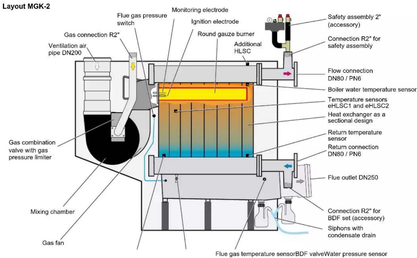
6. Casing
Remove burner hood
(e.g. for servicing the gas-air mixing unit)
- Remove 3 screws on the top of the boiler.
- Lift burner hood slightly and remove from boiler.
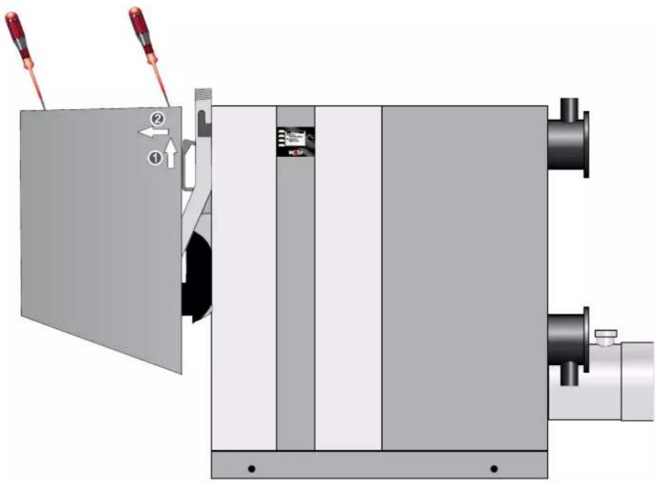
Re-assemble in reverse order.
Open side casing
(e.g. to connect boiler to power supply):
- Remove 2 screws on the right side casing of the boiler.
- Tip right side casing forward and lift off.

natural_image
Technical illustration of a mechanical device with control panel and mounting ports (no text or symbols)Re-assemble in reverse order.
7. Standards and regulations
Observe all standards and guidelines applicable to the installation and operation of this heating system in your country. Observe the information on the boiler type plate.
The following local regulations must be complied with for installation and operation:
• Regulations on installation conditions
- Regulations on the ventilation air and exhaust air and the connection to a chimney
• Electrical connection to the power supply
- The technical regulations of the gas supply utility company regarding the connection of the gas appliance to the local gas mains
- The regulations and standards regarding the safety equipment of the water heating system
- DHW installation
The following general regulations, rules and guidelines must be observed for installation in particular:
• (DIN) EN 1717 Protection of DHW against contamination in DHW installations
- (DIN) EN 12831 Heating systems in buildings – procedure for calculating the standard heat load
- (DIN) EN 12828 Heating systems in buildings – designing hot water heating systems
- (DIN) EN 13384 Flue systems – heat and flow rate calculations
• (DIN) EN 50156-1 (VDE 0116 Part 1) Electrical equipment in combustion systems
• VDE 0470/(DIN) EN 60529 Protection through casings
- VDI 2035 Prevention of damage in hot water heating systems
- Scaling (sheet 1)
- Corrosion in the primary system (sheet 2)
- Corrosion in the flue system (sheet 3)
The following also apply to installation and operation in Germany:
- Technical Regulations for Gas Installations DVGW-TRGI 1986/1996 (DVGW Code of Practice G600 and TRF)
• DIN 1988 Technical regulations for DHW installations
• DIN 18160 Flue systems
• DWA-A 251 Condensate from condensing boilers - ATV-DVWK-M115-3 Indirect discharge of non-domestic waste water Part 3: Indirect discharge practice
- VDE 0100 Regulations regarding the installation of high voltage systems with rated voltages up to 1000 V
• VDE 0105 Operation of high voltage systems, general stipulations - KÜO German Federal Sweeping and Inspection Act
• Energy Savings Act (EnEG) and related ordinances - EnEV Energy Saving Ordinance (currently applicable version)
• DVGW Code of Practice G637
For installation and operation in Austria, the following apply:
- ÖVE regulations
- Provisions of the ÖVGW and the corresponding Austrian standards
- ÖVGV TR-Gas (G1), ÖVGW-RTF (G2)
- Provisions of ÖVGW guideline G41 for condensate drainage
- Local regulations of building and industry regulatory agencies (usually represented by the flue gas inspector)
- Local regulations of the gas supply utility company
• Regulations and requirements of the local power supply utility company - Provisions of regionally applicable building regulations
- Minimum heating water requirements in accordance with ÖNORM H5195-1 must be observed
For installation in Switzerland, the following apply:
- SVGW regulations
- VKF regulations
• BUWAL and local regulations must be observed - G1 gas guidelines
• EKAS form 1942; LPG guideline Part 2
8. Handling / Installation instructions
Handling • With ground conveyor vehicle:
With or without a pallet, the boiler can be handled easily using a pallet truck or forklift, as it can be lifted from any side.

natural_image
Isometric technical diagram of a mechanical device with labeled components and a tool (no text or symbols present)8. Handling / Installation instructions
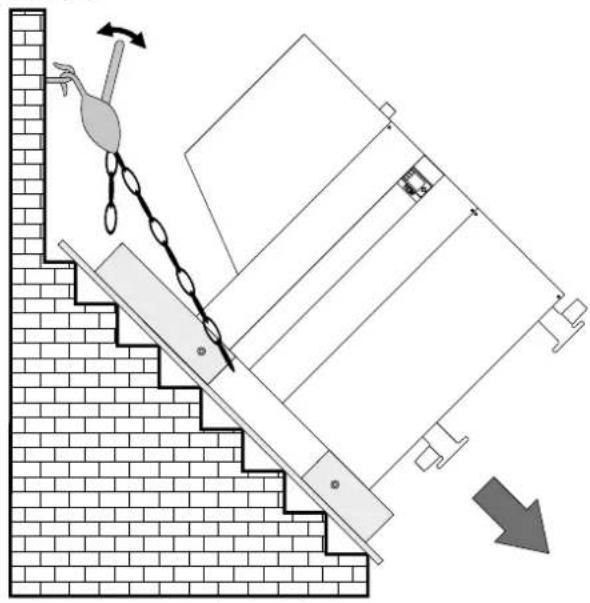
- Can be lowered into the basement with a cable winch or chain hoist, secured to prevent it from sliding down on its own.
Example:
natural_image
Diagram of a crane lifting a block on an inclined ramp, with directional arrows indicating motion (no text or symbols)Dimensions after separating:
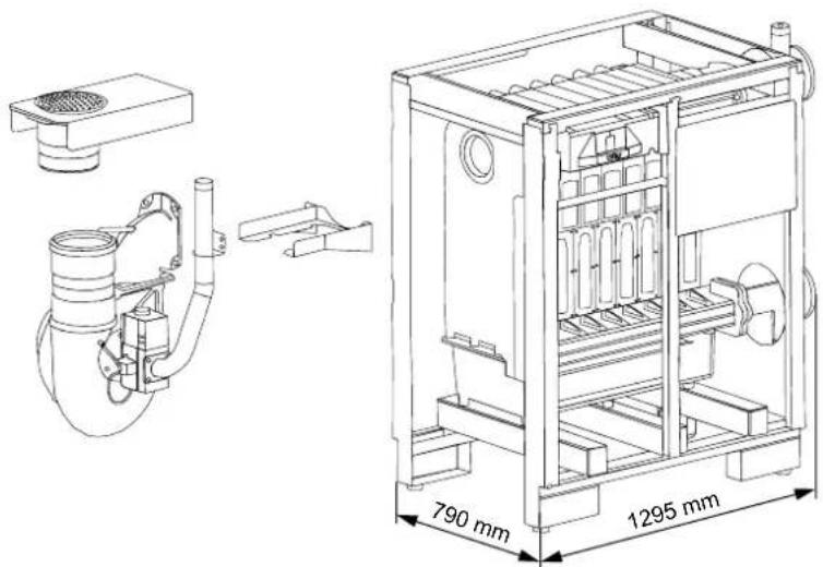
The gas condensing boiler can be separated into a gas-air mixing unit and heat exchanger unit measuring 790 mm x 1295 mm for easier handling.
- Remove the burner hood
- Remove the gas-air mixing unit
- Remove the retainer for the gas-air mixing unit
8. Installation instructions
Installation instructions
- The boiler should be installed on a level surface which is substantial enough to carry its weight.
- The boiler must be level (level with adjustable feet).
Caution
The boiler must only be installed in a room that is protected from frost. If there is a risk of frost while the system is shut down, drain the boiler and the system components that are at risk to prevent pipes from bursting.
Caution
Boilers should not be installed in areas subject to aggressive vapours, very dusty or highly humid conditions (workshops, wash rooms, hobby rooms etc.). This prevents the optimum burner function from being achieved.

The installation room and the combustion air supplied to the boiler must be free from halogenated hydrocarbons (e.g. as contained in sprays, solvents, cleaning fluids, paints and adhesives). At worst these can lead to pitting of the boiler and even the flue system.

Never store or use combustible material or liquids near the boiler.

The ventilation air supply must be ensured and must comply with local regulations or those relating to gas installations. An insufficient fresh air supply can lead to flue gas escaping, which represents a risk to life (poisoning/suffocation).
A neutralising system for the condensate is a basic requirement and is available as an accessory.
Minimum clearances:
Different minimum clearances must be observed when installing the boiler in the installation room.
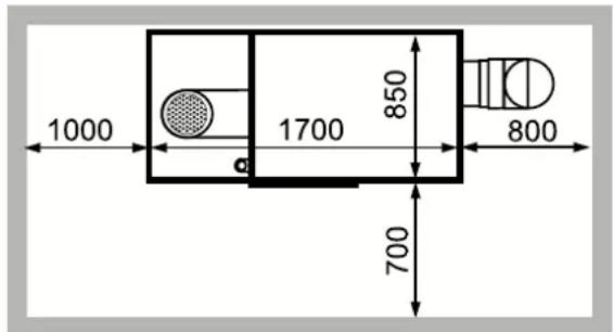
Fig: Boiler in the installation room
Equipment level to DIN EN 12828 for MGK-2
The safety equipment for central heating systems must comply with DIN EN 12828. This standard applies to all hot water heating systems and heat generation systems with a maximum operating temperature of 105 °C and a maximum output of 1 MW.
Note: Provide a drain and fill valve at the lowest system point.
The minimum system pressure is 0.8 bar. The gas condensing boilers are approved exclusively for sealed unvented systems up to 6 bar (safety assembly accessories 3 bar). The maximum flow temperature is factory-set to 85 °C on the MGK-2 and may be adjusted to 90 °C if required.
There is no need for a minimum throughput at maximum flow temperatures below 85 °C.
| Task Function MGK-2 installation location Comments | |||
| Temperature indicator (°C) | Display Integrated in boiler | ||
| High limit safety cut-out (HLSC) | Device to prevent flow temperature being exceeded | Integrated in the boiler, 2nd HLSC integrated in boiler (eHLSC) | Second electronic high limit safety cut-out already integrated in boiler |
| Temperature controller Device to prevent flow temperature being exceeded | Integrated in boiler and set to 85 °C | Max. setting 90 °C | |
| Low water indicator Low water indicator Device to prevent incorrect heating when water level or volume flow are insufficient | In flow line near MGK-2 Can be substituted by minimum pressure limiter. | ||
| Flow limiter Functions like low water indicator | Not required Replaced by maximum pressure limiter | ||
| Water level limiter Functions like low water indicator | Not required Replaced by minimum pressure limiter | ||
| Pressure measuring device (bar) | Display Integrated in boiler Integrated in safety assembly | as accessory | |
| Safety valve Facility to prevent permissible operating pressure being exceeded | Flow line near heat source | Integrated as accessory (up to 3 bar) in the safety assembly | |
| Maximum pressure limiter | Devices for preventing the permissible operating pressure being exceeded | In flow line near MGK-2 2nd maximum pressure limiter that can be integrated in Wolf safety assembly (accessory) | Two can be installed as accessories in MGK-2 safety assembly accessory |
| Flash trap | Facility to prevent permissible operating pressure being exceeded | Near safety valve or replaced by 2nd HLSC (already integrated) and 2nd maximum pressure limiter | Can be replaced by 2nd maximum pressure limiter and 2nd high limit safety cut-out |
| Expansion vessel diaphragm | Device to compensate for changes in water volume (external pressure maintenance) | Return line | Expansion vessels should be able to be securely isolated and emptied for maintenance purposes |
The system must be cleaned / flushed thoroughly before commissioning and a sludge filter/dirt trap (e.g. Wolf accessory, <500 m = 0.5 mm mesh width MW) installed in the return line. This must be in close proximity to the heating appliance and at the lowest position in the heating system.
The fill and top-up water must only be treated with a desalination process. The "Maximum permissible total hardness" table shows the degree to which water treatment is required.
The system water must not fall below a total hardness of 2^ dH, which corresponds to conductivity of ≈ 60 S/cm . The max. permissible total hardness and the corresponding max. conductivity are system-specific and must be calculated (see also "Maximum permissible total hardness" table). The desalinated water (conductivity ≤ 30 S/cm ) must not be mixed with untreated DHW.
The addition of chemicals or de-scaling using single-stage ion exchangers is not permissible, as system damage due to water leaks may occur.
We recommend regular emptying of the sludge filter.
The operator must ensure that the heating system is maintained and serviced regularly to maintain its energy quality (see EnEV).
The Wolf system and operator's log for treatment of heating water must be kept in a safe place and made available by the owner / operator. It is provided along with these installation instructions.
Treatment of heating water in accordance with VDI 2035: We recommend a heating water pH value of between 8.2 and 8.5, also in mixed installations with various materials.
Request a water analysis from the water utility company. This must test whether the total hardness is sufficiently low.
For a specific system volume of V_S,specific ≥ 10 l/kW, the next lowest limit from the table below must be applied,
for V_S,specific >= 20 l/kW the next but one lowest limit, and for V_S,specific >= 40 l/kW the lowest limit.
For a specific system volume of >50 l/kW, the total hardness must be adjusted to 2-3°dH using a desalination process. This corresponds to conductivity of 60 - 100 μS/cm.
If the heating appliance is integrated in the system without a hydraulic low loss header, the total hardness must be adjusted to 2 - 3°dH (conductivity = 60 - 100 μS/cm).
If the water is not treated, the warranty is voided.
Maximum permissible total hardness table:
| Limits depending on the spec. system volume VS (VS = system volume / lowest individual output)Total hardness conversion: 1 mol/m3= 5.6°dH | ||||||||||
| Total heating output | VS ≤ 10 l/kW VS > 10 l/kW and < 40 l/kW VS ≤ 40 l/kW | |||||||||
| Total hardness / total alkaline earths | Conductivity | Total hardness / total alkaline earths | Conductivity | Total hardness / total alkaline earths | Conductivity | |||||
| [kW] | [°dH] | [mol/m3] | C [μS/cm] | [°dH] | [mol/m3] | C [μS/cm] | [°dH] | [mol/m3] | C [μS/cm] | |
| 1* | < 50 | 2 - 16.8* | 0.36 - 3.0* | 60 - 500 | 2 - 11.2 | 0.36 - 2.0 | 60 - 300 | 2 - 3 | 0.36 - 0.54 | 60 -100 |
| 2 | 50-200 | 2 - 11.2 | 0.36 - 2.0 | 60 - 300 | 2 - 8.4 | 0.36 - 1.5 | 60 - 200 | 2 - 3 | 0.36 - 0.54 | 60 -100 |
| 3 | 200-600 | 2 - 8.4 | 0.36 - 1.5 | 60 - 200 | 2 - 3 | 0.36 - 0.54 | 60 -100 | 2 - 3 | 0.36 - 0.54 | 60 -100 |
| 4 | >600 | 2 - 3 | 0.36 - 0.54 | 60 -100 | 2 - 3 | 0.36 - 0.54 | 60 -100 | 2 - 3 | 0.36 - 0.54 | 60 -100 |
*) for system boiler (<0.3 l/kW) and systems with electric heating elements
Gradual increase in the requirement for the spec. system volume (VS = system volume / lowest individual output) and the total heating output.
The total amount of fill water over the life cycle of the appliance must not exceed three times the nominal volume of the heating system.
Please note: The total hardness must not fall below 2^ dH.
11. Boiler system pipework
Heating flow and return are on the right-hand side of the boiler. Always provide shut-off valves for the flow and the return.
Install a check valve downstream of the boiler circuit pump(s) to prevent incorrect circulation.
For new systems we recommend installing a blow-down tank (or alternatively a dirt filter) into the return. For older systems this installation is compulsory.

Install a safety assembly comprising a safety valve with a response pressure of max. 6 bar, a pressure gauge and an automatic air vent valve.
The line between the boiler and the safety valve must not be able to be shut off. Severely excessive boiler pressure due to excessive boiler water temperatures can burst the boiler body or the boiler pipework, which would lead to a sudden escape of hot water (risk of scalding).
When using pipes and climate-controlled floors that are not impermeable to oxygen, always provide system separation by means of a heat exchanger.
Caution
This boiler is only suitable for heating systems with pumped heating circuits. If no heating circuit pump has been installed, sufficient circulation through the radiators cannot be ensured and the room will not be heated.

12. Selection of circulation pumps
The MGK-2 is supplied without a circulation pump. The pump rate of the pump to be supplied by the customer must be determined depending on the system and boiler pressure drop. The fan's power supply and speed control are via the MGK-2 (see electrical connection).
The primary and secondary circuit pumps should generally have the same flow rate. The pumps shown below are designed for a spread of 20 K. If the spread on the secondary side is smaller, a larger pump must be selected on the primary side. The maximum flow rates under 4. Specification must be observed.
The following pumps are recommended for the assembly of an MGK-2 with low loss header.
Wilo
| Nominal flow rate at 20 K Spread [m3/h] | HE pressure drop at 20 K Spread [mbar] | Wilo type | Delivery head [mbar] | Residual head [mbar] | Output [W] | Current [A] | Connection | |
| MGK-2 390 | 17.2 120 Stratos 50/1-2 770 6 | 50 590 2.6 | 1~230V DN 50 flange fitting | |||||
| MGK-2 470 | 20.2 113 Stratos 50/1-12 680 | 567 590 2.6 | 1~230V DN 50 flange fitting | |||||
| MGK-2 550 | 23.7 126 Stratos 65/1-12 730 | 604 800 3.5 | 1~230V DN 65 flange fitting | |||||
| MGK-2 630 | 26.7 118 Stratos 65/1-12 655 | 537 800 3.5 | 1~230V DN 65 flange fitting |
Grundfos
| Nominal flow rate at 20 K Spread [m3/h] | HE pressure drop at 20 K Spread [mbar] | Grundfos Type | Delivery head [mbar] | Residual head [mbar] | Output [W] | Current [A] | Connection | |
| MGK-2 390 | 17.2 120 | Magna3 50-120F | 730 610 | 540 2.4 | 1~230V DN 50 flange fitting | |||
| MGK-2 470 | 20.2 113 | Magna3 50-120F | 640 527 | 540 2.4 | 1~230V DN 50 flange fitting | |||
| MGK-2 550 | 23.7 126 | Magna3 50-150F | 650 524 | 630 2.8 | 1~230V DN 50 flange fitting | |||
| MGK-2 630 | 26.7 118 | Magna3 50-180F | 680 562 | 760 3.4 | 1~230V DN 50 flange fitting |
- The maximum power consumption of the circulation pump must not exceed 4 A.
- Reductions from DN80/PN6 to DN/50 or DN65/PN6 are required for the hydraulic connection of the pumps.
- For the speed control of the circulation pump via the 0-10 V or PWM output of the boiler control unit, an extension module may be required from the pump manufacturer.
13. Gas connection
Gas connection R2"

With the power supply disconnected, connect the gas supply line to gas connection R2" at the gas connection or the expansion joint (recommended) using the approved sealant.

Routing the gas pipe and making the gas connections must only be carried out by a licensed gas fitter.
Remove all residues from the heating pipework and the gas line prior to connecting the condensing boiler, particularly in older systems. Prior to commissioning, test all pipe and gas connections for leaks. Inappropriate installation or using unsuitable components or assemblies may lead to gas escaping, which results in a risk of poisoning and explosion.

Install a gas ball valve with fire protection in the gas supply line upstream of the Wolf condensing boiler. Otherwise explosions may occur during a fire. Size the gas supply line in accordance with DVGW-TRGI regulations.

Check the gas line for tightness without the boiler. Never release the test pressure via the gas valve.

Gas fittings on the appliance should be pressure tested to a maximum of 150 mbar. Higher pressure may damage the gas train, resulting in a risk of explosion, suffocation or poisoning. Close the gas ball valve on the gas condensing boiler to pressure test the gas line.

Mount the gas ball valve in an easily accessible place.
- Prior to installation, ensure that the boiler is set to the available gas type.
At the factory, the boiler is set up for natural gas E/H 15.0:
$$ \mathrm{Ws} = 1 1. 4 - 1 5. 2 \mathrm{kWh} / \mathrm{m} ^ {3} = 4 0. 9 - 5 4. 7 \mathrm{MJ} / \mathrm{m} ^ {3} $$
Only commission the appliance when the rated supply pressure has been reached.
If the supply pressure for natural gas (flow pressure) lies outside the 18 to 25 mbar range, adjustments must not be carried out and the boiler must not be put into operation.
14. Fitting the siphons
The standard delivery includes:
1 x condensate trap (under the burner hood on the ventilation air pipe)
2 x siphons with 3 condensate hoses and 1 tee (on the condensate trap)
Condensate connection:
Install condensate trap in the flue outlet of the condensate pan. Check tightness of the connections.
Install siphons:
Install the first siphon on the connector of the condensate pan.
Install the second siphon on the connector of the condensate trap.

Fill the siphons with water prior to commissioning. Otherwise there is a risk of flue gas escaping.
Connect the condensate hoses of both siphons from the condensate pan and condensate trap with a tee and connect to the neutralising system.

Check tightness of the connections.

natural_image
Close-up of a mechanical device with a white cylindrical component and black circular components, no visible text or symbols.
natural_image
Close-up of a transparent plastic hose attached to a wall, no visible text or symbols
natural_image
Close-up of a transparent glass container with liquid, mounted on a mechanical device (no visible text or symbols)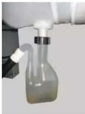
natural_image
Close-up of a glass bottle with a cap and side port, suspended by tubing (no visible text or symbols)
natural_image
Close-up of a mechanical device with a bottle and connecting rod (no visible text or symbols)Installing the neutralising system with booster pump
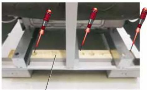
The Neutrakon neutralising system type 08/BGN with booster pump for intensive pH regeneration, which is available as a Wolf accessory, can be slid under the boiler. Firstly remove the wooden slats for boiler transport. The booster pump can be mounted on the boiler crossbar.
Ensure even distribution of the granulate. The inlet and drain must not be covered with granulate.
Observe the installation and maintenance instructions supplied with the neutralising system.
Neutrakon neutralising system installation Type 8/BGN:
- Remove black plug-in strainers (transport safeguard) on the inlet and drain and fit hose connections with pipe strainer. HT pipe connection possible.
- Distribute the granulate evenly by shaking the Neutrakon. The granulate must not completely cover the inlet and drain (risk of blockage).
- Secure booster pump to the crossbar with Velcro strip.
- Fit air hose to the booster.
- Connect the booster cable with the plug on the cable set.
- Always fit the booster above the neutralising system to prevent condensate flowing into the booster.

The booster pump must always be installed higher than the neutralising system. Danger of electrocution!
Function check
The first fill of granulate lasts for at least one year with approx. 2000 hours of operation p.a., provided the system is operated correctly. To ensure smooth functioning, the neutralising system must be checked at least once a year.
- Check fill level. If the granulate level is below the maximum mark (red label), it needs refilling. Neutralisation can only take place when the water flows through the granulate. The granulate fill level must always be above the condensate level.
- Measure pH value with pH indicator strip. if the pH value is below 6.5, the neutralising system needs servicing.

Condensate lifting system
Booster pump mounted on crossbar
natural_image
Close-up of two red screwdrivers working on a metal frame structure (no text or symbols visible)Wooden slat

natural_image
Close-up of a laboratory setup with a glass bottle, tubing, and a mechanical component (no visible text or symbols)Air hose

natural_image
Two views of a mechanical testing setup with black leather components and wiring (no visible text or symbols)Condensate lifting system
Booster and condensate pump connection (connections on cable set behind the strut)
16. Neutralising system / condensate pump (accessories)
Servicing the neutralising system
- Release the connection fittings, detach the booster air hose, disconnect the neutralising system from the inlet and drain and pull it out from under the boiler.
- Loosen any granulate that is stuck together. Do not use sharp objects, as these may damage the casing. Discolouration of the granulate does not impair the neutralisation effect. If there is a large build-up of sludge or the granulate is very stuck together, completely replace the granulate.
Fill with fresh granulate up to the fill level indicated by the label.
- Open hose clip (9) on the maintenance cover (8) and remove cover.
- Empty contents into a suitable container (e.g. bucket).
Loosen soiled granulate and clean neutralising system with water. (Do not use sharp objects, as these may damage the casing.)
- Fill the vertical pipes with granulate up to the fill level label (6).
- Fit maintenance cover (8) on the pipes and secure with pipe clip (9).
- Reconnect inlets and drains. Check for leaks.
Do not fill completely! In type 08/BGN neutralising systems, leave at least 4 cm of space above the granulate.
The inlet and drain openings must not be completely covered with granulate, or a blockage may occur.
- Fit plug-in strainer (HT pipe DN40) and/or hose connection with pipe strainer, seal ring and slide ring and fasten the connection fitting.
Install neutralising system.
Check connections for leaks.
Disposal
Granulate residue can be disposed of in normal household waste.
Condensate lifting system (accessory)
The Wolf condensate lifting system is fully wired and can be integrated into the MGK-2. The power supply and the alarm output of the condensate lifting system are connected to the cable set.
Including 6 m PVC hose for draining off the condensate.
Please note:
To fit the drain of the neutralising system directly into the inlet of the condensate lifting system, the pump and cover must be rotated by 180^ in relation to their factory setting.

natural_image
Hand pressing a mechanical component with a red curved arrow indicating rotation (no text or symbols)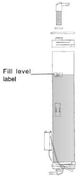

1 Air hose with non-return valve
2 Neutrakon granulate GN
3 Velcro strip
4 Booster pump
5 Min - Max label
6 Fill level label
7 Neutralising system casing
8 Maintenance cover
9 Hose clip, cover
10 Hose clip, connection
11 Pipe spout with strainer

Air/flue gas routing

| Boiler type | Gas boiler type1) | Category | Operating mode Can be connected to | ||||||
| Open flue | Room sealed | Moisture-resistant chimney | Balanced flue chimney | Balanced flue system | Building regulation approved flue pipe | Moisture-resistant flue pipe | |||
| MGK-2 B23, | B23P,C33, C43,C53, C63,C83, C93 | I_2ELL^2) I_2H^3) | Yes Yes | C83 C43 C33, | C53, C63 | C53, C63 B | 23, C53,C83 | ||
1) For type B23, the combustion air is drawn from the installation room (open flue gas combustion equipment). The combustion air supply must come from outdoors (cf. DVGW-TRGI).
2) Germany
3) Austria / Switzerland
For type C, the combustion air is drawn through a sealed system from the outside (balanced flue gas combustion equipment). To allow this, the grille on the ventilation air pipe must be removed.
For type C and pressurised flue gas routing without special tightness requirements, a vent measuring 1x150 cm ^2 or 2x75 cm ^2 is needed in the installation room.
Air/flue gas routing
Single boiler system:
| Implementation versions, condensing boiler | Maximum length in metres, vertical | |||||
| MGK-2 390 | 470 | 5$0 630 | ||||
| B23 F | Flue in a duct and combustion air directly via the boiler (open flue) | DN160 * | 8 | - | - | - |
| DN200 | 50 | 40 | 19 | 9 | ||
| DN 250 | 50 | 50 | 50 | 50 | ||
| B33 | Connection to a moisture-resistant flue gas chimney with horizontal connection line | DN250 DN315 | Calculation to EN 13384 (balanced flue manufacturer) | |||
| C33 | Combustion air supply and flue gas routing via the roof in a common pressure range | DN250 DN315 | Calculation to EN 13384 (balanced flue manufacturer) | |||
| C33 | Vertical concentric roof outlet through a pitched or flat roof, vertical concentric air/flue gas routing for installation in a duct (balanced flue) | DN250/350 DN315/400 | 38 | 27 | 13 | 4 |
| 47 | 38 | 22 | 13 | |||
| C43 | Connection to a moisture-resistant balanced flue chimney (balanced flue) | DN250 DN315 | Calculation to EN 13384 (balanced flue manufacturer) | |||
| C53 | Terminals of the combustion air and flue are in different pressure ranges (balanced flue) | DN200 DN250 | 35 | 22 | - | - |
| 50 | 50 | 50 | 24 | |||
| C53 | Connection to flue on an external wall with horizontal eccentric connection line (length 2.5 m) (balanced flue) | DN200/300 DN250/350 DN315/400 | 39 | 24 | - | - |
| 50 | 50 | 50 | 34 | |||
| - | - | - | 50 | |||
| C63 | The flue gas system has not been tested and certified with the appliance. It must meet the building requirements of the relevant country. | DN250 DN315 | Calculation to EN 13384 (balanced flue manufacturer) | |||
| C83 | Connection to a moisture-resistant chimney and combustion air through an external wall (balanced flue) | DN250 DN315 | Calculation to EN 13384 (balanced flue manufacturer) | |||
| C93 | Vertical flue for installation in a duct with horizontal eccentric connection line, balanced flue ventilation air supply DN200. The terminals are in the same pressure range, combustion air supply via existing duct (edge length in mm) | DN250/250 370x370 DN250/315 450x450 DN315/315 450x450 | 50 | 45 | 16 | - |
| - | 50 | 50 | 23 | |||
| - | - | - | 33 | |||
* Applies to horizontal connection line DN 200 with length of 2 m and an 87° bend (corresponds to 3 m effective length)
Comments:
- Length of connection line: 2 m, 1 additional 87° bend (corresponds to 3 m effective length)
Duct cross-section = minimum annular gap to DIN 18160 Part 1
• Available fan draught: MGK-2: 10 - 150 Pa (maximum length corresponds to the total length from the appliance to the flue terminal)
Note:
- Systems C33 and C83 are also suitable for installation in garages.
- Where necessary, adapt the installation examples to the relevant Building Regulations and requirements in your country/region. Discuss any questions relating to the installation of inspection covers and ventilation air supplies with your local flue gas inspector.
- The length dimensions refer to concentric balanced flue systems and flues, specifically only to original Wolf components.
• The following balanced flues or flues with CE-0036-CPD-9169003 certification may be used:
- Flue DN 160, DN 200, DN 250 and DN 315
- Concentric balanced flue DN 250/350 and DN 315/400
- The necessary identification labels are supplied with the Wolf accessory concerned.
- Please also observe the installation information supplied with the accessories.
18. Electrical connection
General information, electrical connection

The installation must be carried out by a licensed electrical contractor. Observe VDE regulations and all local regulations of your power supply utility company.

For installation in Austria: The ÖVE regulations and requirements and those of your local power supply utility company must be observed.
An omnipolar isolator with at least 3 mm contact separation must be integrated in the power cable upstream of the boiler. A connection box must also be installed by the operator, as per ÖVE requirements.

Do not route sensor leads with 230 V mains cables.

Danger due to live electrical components.
Please note: Turn off the ON/OFF switch before removing the casing.
Never touch electrical components or contacts when the ON/OFF switch is in the ON position. This can result in a risk of electrocution that could lead to injury or death.
The terminals are live even when the ON/OFF switch is in the OFF position.

During servicing and installation work, isolate the entire system from the power supply at all poles, otherwise there will be a risk of electrocution.
Either an AM display module or a BM2 programming module can be installed in the front panel for operating the boiler.
The ON/OFF switch (integrated in the Wolf logo) switches the appliance OFF at all poles.

18. Electrical connection
Remove the cover of the control unit
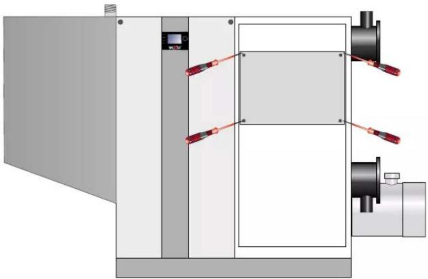
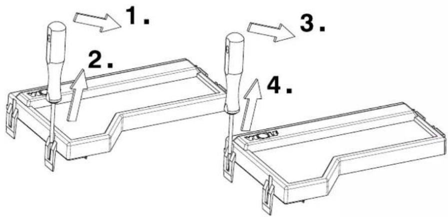
Remove the front casing (see "Casing" chapter), then remove the 4 screws on the control unit with a screwdriver.
natural_image
Technical diagram of a mechanical device with red clamps and control panel (no text or symbols)Remove the HCM-2 casing cover
Overview of components in the control unit
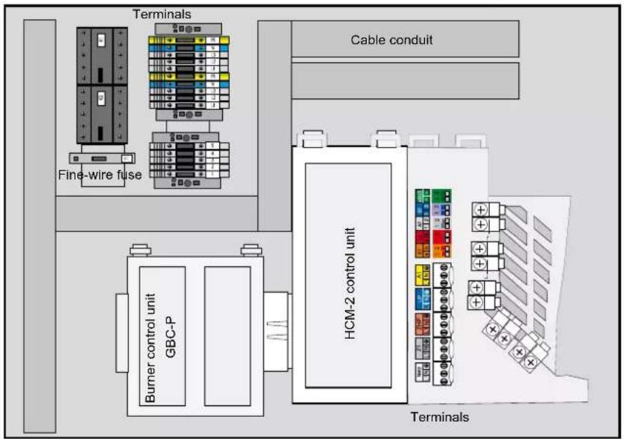
Connections in the control unit

Boiler connection (230 V/400 V):
The control, regulating and safety equipment are fully wired and tested.
You only need to connect the power supply, the heating circuit pump and the external accessories.
Create a permanent connection for the power supply.
Provide the power supply via a mains isolator (e.g. heating emergency stop switch) that ensures at least 3 mm contact separation for all poles.
Installation information, electrical connection, mains
- Isolate the system from the power supply before opening.
- Check that the appliance is isolated from the power supply.
- Open the front casing and the cover of the control unit.
- Open the upper cable conduit and the lower casing cover of the HCM-2.
- Ensure separation of the LV and ELV side.
- Strip approx. 70 mm insulation off the power cable.
- Depending on the heating circuit pump used (230 V/400 V), lay a 3-core or 5-core power cable through the strain relief on the right hand side of the appliance and in the cable conduit to the series terminals.
- Terminate wires at the series terminals as shown in the wiring diagram. Leave the wires for the earth conductor gr/ye approx. 10 mm longer than those for L (L1, L2, L3) and N.
- Close the cable conduits and the cover of the control unit.

Fig: Mains connection
Installation information, electrical connection, heating circuit pump
- Isolate the system from the power supply before opening.
- Check that the appliance is isolated from the power supply.
- Open the front casing and the cover of the control unit.
- Open the upper cable conduit and the lower casing cover of the HCM-2.
- Ensure separation of the LV and ELV side.
- Strip approx. 70 mm insulation off the power cable.
- Depending on the heating circuit pump used (230 V/400 V), lay a 3-core or 5-core power cable for the heating circuit pump through the strain relief on the right hand side of the appliance and in the upper cable conduit to the series terminals.
- Ensure separation of the LV and ELV side.
- Terminate wires accordingly at terminals X1-L1/L2/L3/N/PE. Leave the wires for the earth conductor gr/ye approx. 10 mm longer than those for L (L1, L2, L3) and N.
- When using a variable speed pump, route the signal line through the lower cable conduit.
PWM-controlled pumps must be connected to terminals X2-3 and X2-2(GND). Connect pumps with a 0-10 V control to X2-1 and X2-2. - Close the cable conduits and the cover of the control unit.
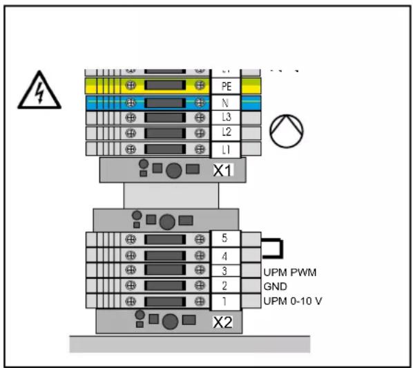
Fig: Connection, heating circuit pump
Connection output A1 (230 V AC; max. 1.5 A) \*
Insert and secure the connecting cable through the cable gland.
Connect the connecting cable to terminals L1, N and ⊥.
The parameters for output A1 are described in the table.
* Max. 1.5 A / 345 VA per output, no more than 600 VA in total for all outputs

Fig: Connection output A1
Connection output Z1 (230 V AC; max. 1.5 A) \*
Insert and secure the connecting cable through the cable gland. Connect the connecting cable to terminals L1, N and ⊥.
* Max. 1.5 A / 345 VA per output, no more than 600 VA in total for all outputs
Connection output primary pump (230 V AC; max. 1.5 A)
Insert and secure the connecting cable through the cable gland. Connect the connecting cable to terminals L1, N and
* Max. 1.5 A / 345 VA per output, no more than 600 VA in total for all outputs
Changing the fuse (HCM-2)
Isolate the condensing boiler from the power supply before changing a fuse.
The ON/OFF switch on the boiler does not provide separation from the power supply.
The fuse is located under the top casing cover of the HCM-2. Danger due to live electrical components. Never touch electrical components or contacts as long as the condensing boiler has not been isolated from the power supply. Risk to life.
Changing the fuse (booster fuse)
- Isolate the gas condensing boiler from the power supply before changing a fuse. The ON/OFF switch on the boiler does not provide separation from the power supply.
- Danger due to live electrical components. Never touch electrical components or contacts as long as the gas condensing boiler has not been isolated from the power supply. Risk to life.
Low voltage boiler connection:
Connection input E1
Insert and secure the connecting cable through the cable gland. Connect the connecting cable for input 1 to terminals E1 in accordance with the wiring diagram; first remove the jumper between 1 and 2 from the respective terminals.
Caution
No external voltage must be connected to input E1, as this could would destroy the control PCB.
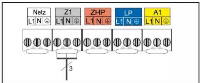
Fig: Connection output Z1
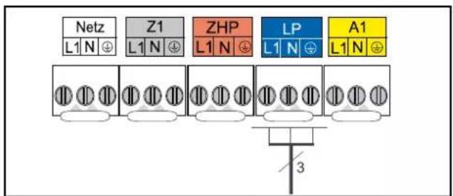
Fig: Connection output LP
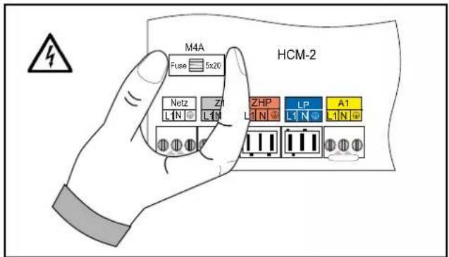
Fig: HCM-2 fuse change

Fig: Booster fuse

Fig: Connection input E1
Low voltage boiler connection:
Connection input E2
Insert and secure the connecting cable through the cable gland. Connect the connection cable for input 2 to terminals E2 as shown in the wiring diagram.
Caution
Only one external voltage of max. 10 V can be connected to input E2, otherwise the control PCB will be destroyed. 1(a) = 10 V, 2(b) = GND

Fig: Connection input E2
Connection, outside temperature sensor
The outside temperature sensor can only be connected to the terminal strip of the AF condensing boiler connection or the terminal strip of the control accessories, provided a BM2 programming module has been fitted.
Caution
When installing the appliance in places where there is a risk of high electromagnetic interference, it is advisable to fit shielded sensor and eBUS cables. The cable shield should be connected at one end to the PE potential in the control unit.

Fig: Connection, outside temperature sensor
Connection, digital Wolf control accessories (e.g. TM2, MM, KM, SM1, SM2)
Only connect control units from the Wolf accessory range. Each accessory is supplied with its own connection diagram. Use a two-core cable (cross-section > 0.5 mm ^2 ) as the connecting cable between the control unit accessory and the condensing boiler.
Caution
When installing the appliance in places where there is a risk of high electromagnetic interference, it is advisable to fit shielded sensor and eBUS cables. The cable shield should be connected at one end to the PE potential in the control unit.

Fig: Digital Wolf control accessories connection (eBUS interface)
Installing the electrical connection of the external safety circuit
An external safety circuit (e.g. maximum pressure limiter) can be connected to the floating contact.
Lockout for as long as the contact is open.
- Isolate the system from the power supply before opening.
- Check that the appliance is isolated from the power supply.
- Open the front casing and the cover of the control unit.
- Open the upper cable conduit and the lower casing cover of the HCM-2.
- Remove the jumper at terminals X2-4 and X2-5.
- Push the potential-free connecting cable of the external component through the strain relief on the right-hand side of the appliance and lay it in the lower cable conduit to the series terminals X2.
- Ensure separation of the LV and ELV side.
- Terminate wires accordingly at terminals X2-4 and X2-5.
- Close the cable conduits and the cover of the control unit.

Fig: Connection of external safety circuit
19. Display / programming module / installation
Either an AM display module or a BM2 programming module must be installed for operating the MGK-2.
AM BM2
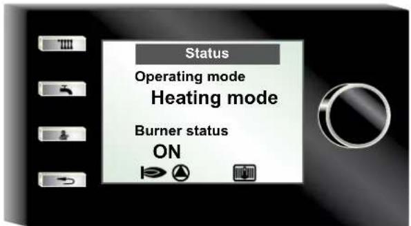
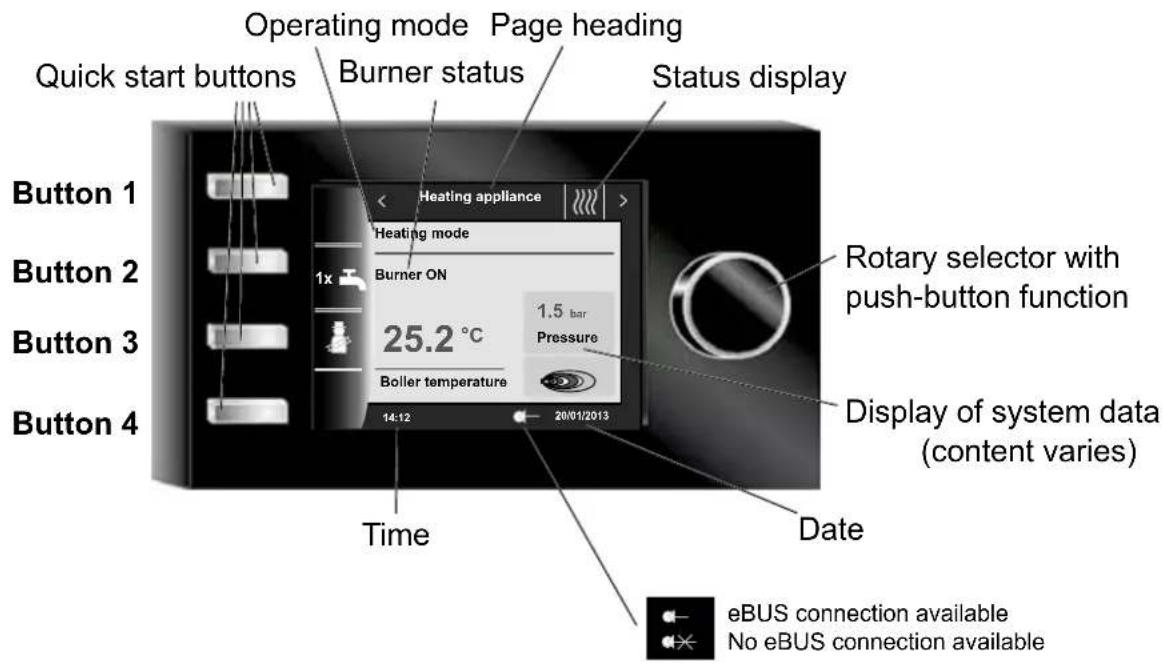
The AM functions solely as a display module for the heating appliance. Heating appliance-specific parameters and values can be programmed and displayed.
Specification:
- LCD display 3"
• 4 quick start buttons
• 1 rotary selector with push-button function - Use when BM2 is used as a remote control or in a cascade circuit
• AM is always in the heating appliance
NB:


The BM2 (programming module) communicates with the heating appliance and all connected extension modules via eBUS.
Specification:
- Colour display 3.5", 4 function buttons, 1 rotary selector with push-button function
- Micro SD card slot for software update
- Central programming unit with weather-compensated flow temperature control
• Time program for heating, DHW and DHW circulation
Remove the front panel of the MGK-2 and refit it after installation of the module.
Insert the AM or BM2 in the slot above the ON/OFF switch (Wolf logo).
Both modules can be plugged into this slot. Further commissioning or address assignment measures specific to the BM2 can be found in the BM2 installation instructions.
Switch ON power supply / activate MCB and switch ON/OFF switch to ON on the MGK-2.
Overview AM
Note:
If your Wolf heating appliance does not have an AM display module, ignore this page.
Other functions and descriptions can be found in the installation instructions for contractors or the user operating instructions for the AM display module.
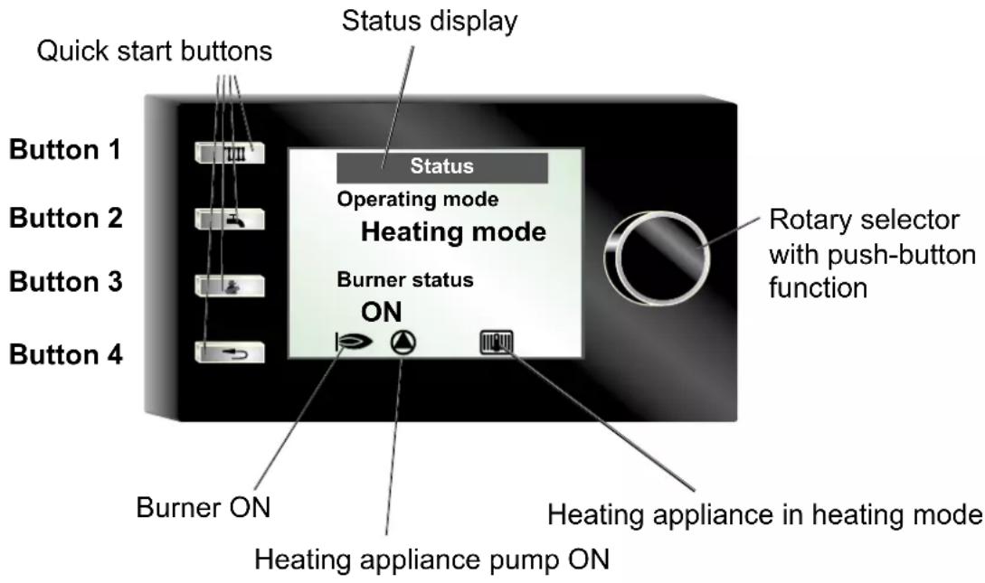
Button 1
Button 2
Button 3
Button 4

natural_image
Black vertical panel with four metallic buttons labeled 'III', a faucet icon, a hand gesture, and a curved arrow (no text or symbols beyond basic icons)Heating appliance set temperature (if BM2 as remote control - no function)
DHW set temperature (if BM2 as remote control - no function)
Enable emissions test mode (for chimney sweep only)
Acknowledge fault / End / Back
21. AM display module menu structure
AM control unit menu structure
Heating appliance
Boiler temperature
System pressure
Status
Operating mode
Burner status
Notification
Display of
faults or
notifications
(see chapter 10)
Main menu
Back
Displays
Default settings
Emissions test
Contractor
Back
Displays
Back
T_boiler in °C
System pressure in bar
T_flue gas current in °C
T_outside in °C
T_return in °C
T_DHW in °C
Input E1
Fan speed rpm
Modulation level in %
Actual I/O value
ZHP speed
Burner starts
Burner hours run
Mains hours
Power ON count
HCM2 firmware
Back
Default settings
Back
Language
Button lock
Back
Emissions test
End
Rem. time in min.
T boiler
T_return
Calibration
Extend time
End
Contractor
Contractor code
1111
Back
Relay test
System
Parameter
Parameter reset
Fault history
Delete fault history
Acknowledge fault
Back
Heating appliance operating mode
| Display indication Function | |
| Start Start the appliance | |
| Standby No heating or DHW demand | |
| Heating mode Heating mode, at least one heating circuit demands heat | |
| DHW mode DHW heating with cylinder, cylinder temperature is below set value | |
| Emissions test Emissions test mode active, heating appliance running at maximum power | |
| Antifreeze HC Boiler frost protection function, boiler water temperature below frost protection limit | |
| Antifreeze DHW Frost protection function of DHW cylinder active, cylinder temperature below frost protection limit | |
| Frost protection System frost protection active, outside temperature below frost protection limit | |
| Heating run-on Heating circuit pump run-on active | |
| DHW run-on Cylinder primary pump run-on active | |
| Parallel mode Heating circuit pump and cylinder primary pump active in parallel | |
| Test | Relay test function has been activated |
| Cascade | Cascade module in system active |
| BMS Appliance is controlled by building management system (BMS) | |
Heating appliance burner status
| Display indication | Function |
| OFF | No burner demand |
| Pre-flush | Fan operation before burner start |
| Ignition | Gas valves and ignition unit are active |
| Stabilisation | Flame stabilisation after safety time |
| Soft start | After flame stabilisation in heating mode, the burner runs at low burner power for the duration of the soft start to prevent cycling |
| ON | Burner operational |
| Cycle block | Burner block after a burner cycle for the duration of the cycle block |
| Op without b. | Operation without burner, input E1 closed |
| Flue gas damper | Waiting for feedback from flue gas damper (input E1) |
| dT too wide Temperature spread between boiler water temperature sensor and return temperature sensor too wide | |
| dT Tboil-eSTB Temperature spread between eHLSC1/eHLSC2 and boiler sensor too wide | |
| Valve test | Gas valve test |
| Grad. control | Boiler water temperature rising too fast |
| Gas pressure | Gas pressure switch has not responded |
| Fault | Burner not operational due to a fault |
| Post-flush | Fan operation after burner shutdown |
Overview BM2
Note:
Other functions and descriptions can be found in the installation instructions for contractors or the user operating instructions for the BM2 programming module.
Button 1
Button 2
Button 3
Button 4

natural_image
Close-up of a black industrial control panel with four slots and a 1x water level indicator (no text or symbols beyond basic symbols)(in this view - no function)
1x DHW heating
Enable emissions test mode (for chimney sweep only)
(in this view - no function)
Caution
Modifications must only be carried out by a recognised heating contractor or by Wolf customer service. Incorrect operation can lead to system faults.
Caution
On the AM display module or the BM2 programming module, the factory setting for the HG parameters can be reinstated in the Contractor menu.

To prevent damage to the heating system, cancel night setback when outside temperatures fall below -12 °C. If this rule is not observed, ice may build up on the flue outlet which may cause injury or material losses.
The control parameters can only be modified or displayed using the AM display module or BM2 programming module on the boiler. For procedures, check the operating instructions of the relevant accessories.
| No. | Description Unit Factory setting Min Max | ||||
| HG01 | Burner hysteresis °C 15 7 30 | ||||
| HG02* | Lower burner output, boilerMinimum burner output | % | 19 19 | 100 | |
| HG03 | Upper burner output, DHWMaximum burner output DHW in % | % | 100 | 19 | 100 |
| HG04 | Upper burner output, heatingMaximum burner output, heating in % | % | 100 | 19 | 100 |
| HG07 | Heating circuit pump run-on timeHeating circuit pump run-on time in heating mode | Min | 1 | 0 30 | |
| HG08 | Maximum boiler water temperature HZ (applicable to heating operation) TV-max | °C 85 40 | 90 | ||
| HG09 | Burner cycle block, applicable to heating operation | Min | 10 | 1 | 30 |
| HG10 | Heat source eBUS address | - | 1 | 1 | 5 |
| HG12 | No function | - | - | - | - |
| HG13 | Function, input E1Various functions can be allocated to input E1. | - | none | div. | div. |
| HG14 | Function, output A1 (230 V AC)Various functions can be allocated to output A1. | - | none | div. | div. |
| HG 15 | Cylinder hysteresis, switching differential during cylinder re-heating | °C 5 | 1 30 | ||
| HG16 | Pump rate HC, minimum | % | 25 15 | 100 | |
| HG17 | Pump rate HC, maximum | % | 100 | 15 | 100 |
| HG19 | SLP run-on time (cylinder primary pump) | Min | 3 | 1 | 10 |
| HG20 | Max. cylinder heating time | Min | 120 | 30/Off | 180 |
| HG21 | Minimum boiler water temperature TK-min | °C 20 20 | 90 | ||
| HG22 | Maximum boiler water temperature TK-max | °C 90 50 | 90 | ||
| HG25 | Boiler excess temperature during cylinder heating | °C 10 1 30 | |||
| HG33 | Burner hysteresis runtime | Min | 10 1 30 | ||
| HG34 | eBUS feed | - | Auto | Off | ON |
| HG37 | Pump control type (constant / linear / dT) | - | dT | div. | div. |
| HG38 | Set dT, pump control unit (dT) | °C 20 0 40 | |||
| HG39 | Soft start time | Min | 3 | 0 10 | |
| HG40 | System configuration (see chapter "Parameter description") | - | 1 | div. | div. |
| HG41 | Speed ZHP DHW | % | 100 | 15 | 100 |
| HG42 | Header hysteresis | °C 5 | 0 20 | ||
| HG43 | No function | - | - | - | - |
| HG44 | No function | - | - | - | - |
| HG45 | No function | - | - | - | - |
| HG46 | Header excess boiler water temperature | °C 6 | 0 20 |
* HG02 controls the fan speed 19 % - fan speed corresponds to 17 % burner output.
Parameter HG01
Burner switching hysteresis
Factory setting:
see table chap. 24
Control unit parameters
Individual settings:
The burner switching hysteresis regulates the boiler water temperature within a set range by switching the burner ON and OFF. The higher the hysteresis, the higher the boiler water temperature fluctuation around the set value, resulting in longer burner runtimes and vice versa. Longer burner runtimes protect the environment and extend the service life of wearing parts.

line
| Burner runtime (min.) | Switching hysteresis (°C) | | --------------------- | ------------------------- | | 0 | 15 | | 10 | 7 |Fig.:
Time sequence of the dynamic burner switching hysteresis for a user-defined burner switching hysteresis of 15 °C and a selected hysteresis time (parameter HG33) of 10 minutes.
Parameter HG02
Lower burner output
Factory setting:
see table chap. 24
Control unit parameters
Individual settings: ____
The setting for the minimum burner output (minimum device load) is applicable to all operating modes. This percentage value corresponds approximately to the real device output.
Parameter HG03
Individual settings: ____
The setting for the maximum burner output in DHW mode (maximum device load). Valid for DHW cylinder heating. This percentage value corresponds approximately to the real device output.
Parameter HG04
Upper burner output HZ
Factory setting:
see table chap. 24
Control unit parameters
Individual settings: ____
The setting for the maximum burner output in heating mode (maximum device load). Valid for heating mode, BMS and emissions test. This percentage value corresponds approximately to the real device output.
25. Parameter description
Parameter HG07
Run-on time, heating circuit pump
Factory setting:
see table chap. 24
Control unit parameters
Individual settings:
If there is no more heat demand from the heating circuit, the feed/heating circuit pump ZHP will run on in accordance with the set time to prevent a boiler safety shutdown at high temperatures.
Parameter HG08
Maximum boiler water temperature HZ TV-max.
Factory setting:
see table chap. 24
Control unit parameters
Individual settings: ____
This function limits the boiler water temperature upwards in heating mode, and the burner shuts down. This parameter has no function during cylinder heating, and the boiler water temperature may also be higher during this time. "Reheating effects" can result in the temperature being slightly exceeded.
Parameter HG09
Burner cycle block
Factory setting:
see table chap. 24
Control unit parameters
Individual settings: ____
Each time the burner is shut down in heating mode, it will be blocked for the duration of the burner cycle block. The burner cycle block is reset by switching the ON/OFF switch OFF and ON or by briefly pressing the reset button.
Parameter HG10
eBUS address of the heat source
Factory setting:
see table chap. 24
Control unit parameters
Individual settings: ____
If multiple heat sources are controlled in one heating system with a cascade module, addresses must be allocated to the heat sources. Each heat source requires its own eBUS address in order to communicate with the cascade module. The activation sequence of the heat sources can be set in the cascade module.
Please note: Duplicated addresses lead to malfunctions of the heating system.
Parameter HG13
Function input E1
The functions of the input E1 can only be read and set directly on the boiler under parameter HG13 using the AM display module or BM2 programming module.
| Display | Description |
| none | No function (factory setting)Input E1 is not taken into consideration by the control unit. |
| RT | Room thermostatWith open input E1, heating operation will be blocked (summer mode) and frost protection mode and emissions test mode will not be blocked, independent of any digital Wolf control accessories. |
| DHW | DHW blocking/enablingWith open input E1, DHW heating will be blocked, independent of any digital Wolf control accessories. |
| RT/DHW | Heating and DHW blocking/enablingWith open input E1, heating operation and DHW heating will be blocked and frost protection mode and emissions test mode will not be blocked, independent of any digital Wolf control accessories. |
| Timer | Timer (DHW circulation button)If input E1 is configured as a DHW circulation button, output A1 is automatically set to "DHW circulation pump" and blocked for further settings. When input E1 is closed, output A1 is activated for 5 minutes. When input E1 has switched off and 30 minutes have elapsed, the timer function is re-enabled for the next operation. |
| Op without b. | Operation without burner (burner blocking)When contact E1 is closed, the burner is blocked.Heating circuit pump and cylinder primary pump continue running in standard mode.The burner is enabled in emissions test mode and in frost protection mode.Opening contact E1 enables the burner again. |
| Flue gas damper | Flue gas damper/ventilation air damperFunction monitoring of the flue gas damper/ventilation air damper with floating contact.Closed contact is a pre-requisite for enabling burner in central heating, DHW and emissions test mode.If input E1 is configured as a flue gas damper, output A1 is automatically programmed as a flue gas damper and blocked for other settings. |
Parameter HG14
Function output A1
The functions of the output A1 can only be read and set directly on the boiler under parameter HG14 using the AM display module or BM2 programming module.
| Display Description | |
| none none | (factory setting)Output A1 is not taken into consideration by the control unit. |
| Timer100 DHW circulation pump 100 %Output A1 is controlled by the time program in the control accessory, if DHW circulation has been enabled.Output A1 is constantly activated when no accessory controller is installed. | |
| Timer50 DHW circulation pump 50 %Output A1 is activated cyclically by the time program in the control accessory, if DHW circulation has been enabled.5 minutes ON, 5 minutes OFF. Output A1 is constantly activated cyclically when no accessory controller is installed. | |
| Timer20 DHW circulation pump 20 %Output A1 is activated cyclically by the time program in the control accessory, if DHW circulation has been enabled.2 minutes ON, 8 minutes OFF. Output A1 is constantly activated cyclically when no accessory controller is installed. | |
| Alarm Alarm outputOutput A1 is activated 4 minutes after a fault. | |
| Flame Flame detectorOutput A1 is activated after a flame has been recognised. | |
| Timer Timer (DHW circulation button)Output A1 is activated for 5 minutes when input E1 closes.If output E1 is configured as a timer, input E1 is automatically set to "Circulation tester" and blocked for further settings. When input E1 has switched off and 30 minutes have elapsed, the timer function is re-enabled for the next operation. | |
| Flue gas damper | Flue gas damper/ventilation air damperOutput A1 is activated first before each burner start. The burner will, however, only be enabled after input E1 has been closed. Closed contact E1 is a pre-requisite for enabling burner in central heating, DHW and emissions test mode.If output A1 is activated and does not close input E1 within 2 minutes, a fault is generated (FC 8).If output A1 is deactivated and does not open input E1 within 2 minutes, a fault is generated (FC 8).If output A1 is configured as a flue gas damper, input E1 is automatically programmed as a flue gas damper and blocked for other settings. |
| Ext. vent. | External ventilationOutput A1 is switched inverse to the gas combination valve. Switching OFF external ventilation (e.g. extractor fan) during burner operation is only required if the boiler is operated as an open flue system. |
| External fuel valve | External fuel valveActivation of an additional fuel valve during burner operation.Output 1 is activated from pre-flushing of the device until burner shutdown. |
25. Parameter description
Parameter HG15
Cylinder hysteresis
Factory setting:
see table chap. 24
Control unit parameters
Individual settings:
The cylinder hysteresis regulates the start point for cylinder heating. The higher the setting, the lower the start point for cylinder heating.
Example: Set cylinder temperature 60 °C
Cylinder hysteresis 5 K
Cylinder heating commences at 55 °C and ends at 60 °C.
Parameter HG16
Pump rate HC, minimum
Factory setting:
see table chap. 24
Control unit parameters
Individual settings: ____
In heating mode, the pump does not regulate below this set value. Independent of pump control type set in HG37.
Parameter HG17
Pump rate HC, maximum
Factory setting:
see table chap. 24
Control unit parameters
Individual settings: ____
In heating mode, the pump does not regulate above this set value. Independent of pump control type set in HG37. If the pump control type is "Constant", HG17 is used as the setting for the pump speed in heating mode.
Parameter HG19
LP run-on time (cylinder primary pump)
Factory setting:
see table chap. 24
Control unit parameters
Individual settings: ____
After completing cylinder heating in summer mode (the cylinder has reached the set temperature), the cylinder primary pump will run on up to the maximum set run-on time.
The cylinder primary pump will switch OFF prematurely if, during the run-on time, the boiler water temperature cools down to a differential between boiler and set cylinder temperature of 5 K.
In winter mode, the cylinder primary pump runs on for a fixed time of 30 seconds after successful cylinder heating (independently of parameter HG19).
25. Parameter description
Parameter HG20
Max. cylinder heating time
Factory setting:
see table chap. 24
Control unit parameters
Individual settings:
Cylinder heating commences as soon as the cylinder temperature sensor demands heat. The heating circuit pumps would be constantly switched off if the boiler was undersized, the cylinder was scaled up or if DHW was constantly drawn off during DHW priority mode. The accommodation cools down significantly. To limit this effect, it is possible to specify a maximum cylinder heating time.
If the set maximum cylinder heating time has expired, error message FC52 appears on the programming or display module.
The control unit reverts to heating mode and cycles in the selected rhythm (HG20) between heating and cylinder heating mode, irrespective of whether the cylinder has reached its set temperature or not.
The function "Max. cyl. heat time" remains active even if parallel pump operation is activated. If HG20 is set to OFF, the function "Max. cyl. heat time" is deactivated. Set this parameter to OFF in heating systems with a high DHW consumption, e.g. hotels, sports facilities etc.
Parameter HG21
Minimum boiler water temperature TK-min
Factory setting:
see table chap. 24
Control unit parameters
Individual settings: ____
The control unit is equipped with an electronic boiler thermostat which has an adjustable minimum start temperature. The burner is switched on subject to the cycle block if this temperature is not achieved when heat is demanded. The minimum boiler water temperature TK-min is not necessarily achieved when there is no heat demand.
Parameter HG22
Maximum boiler water temperature TK-max
Factory setting:
see table chap. 24
Control unit parameters
Individual settings: ____
The control unit is equipped with an electronic boiler thermostat which has an adjustable maximum shutdown temperature (maximum boiler water temperature). The burner is switched off if this temperature is exceeded. The burner will be started again when the boiler water temperature has fallen by as much as the burner switching differential.
Parameter HG25
Excess boiler temp. for cylinder heating
Factory setting:
see table chap. 24
Control unit parameters
Individual settings: ____
The excess temperature differential between the cylinder temperature and the boiler water temperature during cylinder heating is selected with parameter HG25. The boiler water temperature continues to be limited by the maximum boiler water temperature (parameter HG22). This ensures that, even in spring and autumn, the boiler water temperature is higher than the cylinder temperature, thereby ensuring short heating times.
25. Parameter description
Parameter HG33
Burner hysteresis runtime
Factory setting:
see table chap. 24
Control unit parameters
Individual settings:
When starting the burner or changing to heating mode, the burner hysteresis is set to the parameter "Burner switching differential" HG01. Based on this set value, the burner hysteresis within the set "Runtime burner hysteresis" HG33 is reduced to the minimum burner hysteresis of 7 K. This is designed to prevent short burner runtimes.
Parameter HG34
eBUS feed
Factory setting:
see table chap. 24
Control unit parameters
Individual settings: ____
In the "Auto" setting, the power supply of the eBUS system is switched ON or OFF automatically by the control unit, depending on the number of available eBUS subscribers.
OFF = BUS feed is always switched OFF
ON = BUS feed is always switched ON
Auto = the control unit switches the bus feed ON or OFF automatically
Parameter HG37
Pump control type
Factory setting:
see table chap. 24
Control unit parameters
Individual settings: ____
For setting the type of pump speed control in heating mode and with BMS.
Constant = fixed pump speed (HG17)
Linear = linear pump speed between HG16 and HG17 corresponding to the current burner output
dT = speed control between HG16 and HG17 to achieve flow/return temperature spread (HG38)
Parameter HG38
Set dT pump control unit
Factory setting:
see table chap. 24
Control unit parameters
Individual settings: ____
If dT pump control unit is activated in parameter HG37, the set dT specified in HG38 applies. The change to the pump speed means the dT is regulated between flow and return within the speed limits in HG16 and HG17.
Parameter HG39
Soft start time
Factory setting:
see table chap. 24
Control unit parameters
Individual settings: ____
In heating mode, the burner is run at a lower output for the set time after burner start.
Parameter HG40
System configuration
The MGK-2 is fine-tuned to the heating system by selecting from 6 preconfigured system configurations that can only be read and set directly on the boiler under parameter HG40 using the AM display module or BM2 programming module. This parameter affects both the function of the ZHP (feed/heating circuit pump) and the input E2.
System configuration 01
Direct heating circuit on the boiler + optional further mixer circuits via mixer modules (factory setting)
- Burner is activated subject to demand from the direct heating circuit or optionally connected mixer circuits
- Feed/heating circuit pump (ZHP) as heating circuit pump for direct heating circuit
- Boiler thermostat;
set value is specified by heating circuit or mixer circuits
• Input E2: not assigned
Note: If the pressure drop of the boiler incl. the pipework is >700 mbar, a low loss header must be installed.
System configuration 02
One or more mixer circuits via mixer modules (no direct heating circuit on the boiler)
- Burner is activated subject to demand from the connected mixer circuits
- Boiler thermostat;
set value is specified by mixer circuits
• Input E2: not assigned
• Feed/heating circuit pump (ZHP) not active
Note: If the pressure drop of the boiler incl. the pipework is >700 mbar, a low loss header must be installed.
System configuration 11
Low loss header with header sensor
- Burner is activated subject to demand from the header temperature control
- Feed/heating circuit pump (ZHP) activated as feed pump for header demand
• Header temperature control
• Input E2: header sensor
System configuration 11
Plate heat exchanger as system separation
- Burner is activated subject to demand from the header temperature control
- Feed/heating circuit pump (ZHP) activated as feed pump for header demand
• Header temperature control
• Input E2: header sensor
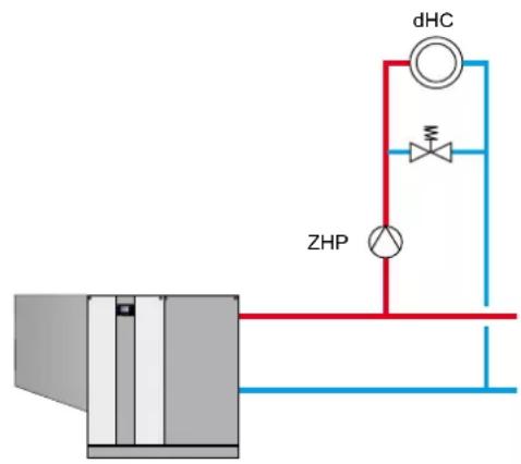
flowchart
graph TD
    A["Valve with DHC"] --> B["Valve with ZHP"]
    B --> C["Pressure Gauge"]
    D["Pressure Gauge"] --> E["Valve with dHC"]
    F["Pressure Gauge"] --> G["Valve with ZHP"]

flowchart
graph TD
    A["Control Unit"] --> B["Valve"]
    B --> C["MM 1"]
    C --> D["Control Unit"]
    D --> E["Valve"]
    E --> F["MM 1"]
    style A fill:#f9f,stroke:#333
    style B fill:#ccf,stroke:#333
    style C fill:#cfc,stroke:#333
    style D fill:#fcc,stroke:#333
    style E fill:#cff,stroke:#333
    style F fill:#ffc,stroke:#333
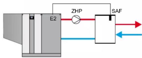
flowchart
graph LR
    A["Component E2"] --> B["ZHP"]
    B --> C["SAF"]
    C --> D["Output"]
    style A fill:#f9f,stroke:#333
    style C fill:#ccf,stroke:#333

flowchart
graph LR
    A["Data Input"] --> B["E2"]
    B --> C["ZHP"]
    C --> D["SAF"]
    D --> E["Output"]
    style A fill:#f9f,stroke:#333
    style B fill:#ccf,stroke:#333
    style C fill:#cff,stroke:#333
    style D fill:#ffc,stroke:#333
    style E fill:#cfc,stroke:#333
System configuration 51
BMS burner output
Burner is activated subject to demand from the external controller
• Feed/heating circuit pump (ZHP) activated as feed pump from 2 V upwards
• No temperature control
- Input E2:
Control 0-10 V by external controller
0-2 V burner OFF,
2-10 V burner output min. to max. within the programmed limits (HG02 and HG04)
• Automatic output reduction when approaching TK_max (HG22) is activated. Deactivation on reaching TK_max
Note: If the pressure drop of the boiler incl. the pipework is >700 mbar, a low loss header must be installed.

System configuration 52
BMS set boiler temperature
- Burner is activated subject to demand from the boiler thermostat
• Feed/heating circuit pump (ZHP) activated as feed pump from 2 V upwards - Boiler thermostat
- Input E2: Control by external controller with 0-10 V 0-2 V burner OFF 2-10 V set boiler temperature TK min (HG21) - TK max (HG22)
Note: If the pressure drop of the boiler incl. the pipework is >700 mbar, a low loss header must be installed.
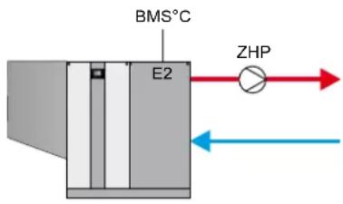
System configuration 60
Cascade for multi boiler systems (setting automatic when cascade module is connected)
- Burner is activated subject to demand from cascade module via eBUS (0-100 % burner output; min. to max. within the programmed limits) (HG02 and HG04)
• Feed/heating circuit pump (ZHP) activated as feed pump
• Header temperature control via cascade module
• Input E2: not assigned
• Automatic output reduction when approaching TK_max (HG22) is activated. Deactivation on reaching TK_max - A low loss header or plate heat exchanger can be used as system separation.

flowchart
graph TD
    A["eBUS"] --> B["ZHP"]
    B --> C["SAF"]
    C --> D["KM"]
    D --> E["ZHP"]
    E --> F["SAF"]
    F --> G["Return to SF"]
    H["eBUS"] --> I["ZHP"]
    I --> J["SAF"]
    J --> K["Return to SF"]
Important information:
In these schematic diagrams, shut-off valves, air vent valves and safety equipment are not fully represented. These should be provided in compliance with the applicable standards and regulations for each individual system.
Hydraulic and electrical details can be found in the Hydraulic System Solutions technical guide.
25. Parameter description
Parameter HG41
Speed ZHP DHW
Factory setting:
see table chap. 24
Control unit parameters
Individual settings:
In DHW mode, the pump runs at this set value. Independent of pump control type set in HG37.
Parameter HG42
Header hysteresis
Factory setting:
see table chap. 24
Control unit parameters
Individual settings:
The header hysteresis regulates the header temperature within the set range by switching the heat source ON and OFF. The higher the ON / OFF temperature differential, the higher the header temperature fluctuation around the set value, resulting in longer heat source runtimes, and vice versa.
Parameter HG46
Header excess boiler water temperature
Factory setting:
see table chap. 24
Control unit parameters
Individual settings: ____
The excess temperature differential between the header temperature and the boiler water temperature during header heating is selected with parameter HG46. The boiler water temperature continues to be limited by the maximum boiler water temperature (parameter HG22).
Flue gas damper power supply
- Isolate the system from the power supply before opening.
- Check that appliance is isolated from the power supply.
- Open the front casing and the cover of the control unit.
- Strip approx. 70 mm off the connecting cable of the flue gas damper motor and signal contact.
- Lay connecting cable from the flue gas damper motor to the screwless terminals, pushing it through the strain relief on the right-hand side of the boiler, and connect it to programmable output A1.
- Lay connecting cable from the limit switch to the screwless terminals, pushing it through the strain relief on the right-hand side of the boiler, and connect it to programmable input E1.
- Close cover of control unit.
Note:
The contractor parameter
HG13 (input 1) must be set to FI gas damp and
HG14 (output 1) must be set to FI gas damp.
When the limit switch is open, the burner is blocked both for DHW and central heating and for emissions test and frost protection.

HCM-2 electrical connection

flowchart
graph TD
    A["Programmable Output"] --> B["Programmable Input"]
    B --> C["Flue Gas Damper"]
    subgraph A1
        D["LP L1 N ⊕ A1 L1 N ⊕"]
        E["E1 (programmable input, e.g. flue gas damper)"]
    end
    subgraph E1
        F["E1 a b E2 a b AF 1 2 1 2 SF + -"]
        G["1 2 1 2 1 2 1 2 1 2"]
    end
    subgraph_M["230V~"]
        H["MB"]
    end
    I["NB. Flue gas dam be potential-free"] --> H
    J["Otherwise the will be destroyed"] --> H
Limit switchFlue gas damper motor
NB.
Flue gas damper limit switch must be potential-free.
Otherwise the MGK-2 control unit will be destroyed.
Damper function test
▶ Start the boiler.
▶ Visual check to ensure damper is open.
▶ Unplug E1 for 2 minutes during operation.
▶ Reconnect E1.
▶ Acknowledge fault message.
▶ Visual check to ensure flue gas damper is closed.
Boiler must lockout with error code 8, with the fan continuing to run at low speed. Fault code 44 "Flu gas prssr swtch" may also appear.
During commissioning and as part of the annual heating appliance test, the cascade damper in overpressure heating appliance systems must be tested for tightness to ensure no CO_2 can escape into the installation room.
Cascades (overpressure), open flue
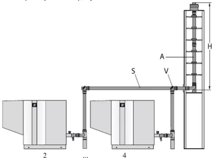
The following basic principles are taken into consideration in all calculations for the sizing tables:
-Length between the individual appliances: 1.0 m
-Length after the last appliance: 2.0 m
-Pressure drops: 2 x 45° bends in the diameter of the header pipe (optionally as lateral offset or 90° diversion)
-Combustion air supply: from installation room
-Duct ventilation: balanced flow principle
-Geodetic height: 325 m
Flue system design
The following overview shows the maximum vertical flue length for open flue positive pressure cascades, with different boiler combinations:
| MGK-2 | VNominal diameter of connection line to the appliance | SNominal diameter of header | ANominal diameter of flue pipe, vertical | ∅/☐Minimum duct sizesround rectangular | HAchievable height from duct inlet to duct outlet | ||
| 390 2x row DN250 D | N250 DN315 420 mm | 400 mm 50 m | |||||
| 3x row DN250 DN315 DN315 420 mm 400 mm 42 m | |||||||
| 4x row DN250 * * * * | * | * | |||||
| 470 2x row DN250 DN250 DN315 420 mm 400 mm 50 m | |||||||
| 3x row DN250 DN315 DN315 420 mm 400 mm 17 m | |||||||
| 4x row DN250 * * * * | * | * | |||||
| 550 2x row DN250 DN250 DN315 420 mm 400 mm 22 m | |||||||
| 400 mm 50 m | |||||||
| 3x row DN250 * * * * | * | * | |||||
| 4x row DN250 * * * * | * | * | |||||
| 630 2x row DN250 DN315 DN315 420 mm 400 mm 23 m | |||||||
| 3x row DN250 * * * * | * | * | |||||
| 4x row DN250 * * * * | * | * | |||||
* Calculation and design to EN 13384-2 – kit on request
A maximum back pressure up to 50 Pa must be maintained in the connection to the header line and must not be exceeded. Only use DIBt approved flue pipes.
In cascade operation, a Wolf cascade controller is required.
27. Cascade operation
Cascade module setting
The standard settings of the Wolf cascade module can lead to cycling in very sluggish heating systems.
For optimum cascade operation, we therefore recommend the following settings:
| Parameter Setting | |
| KM10 20 | |
| KM11 500 |
Pump speed setting
If the circulation and feed pump (ZHP) are controlled by the Wolf boiler control unit during operation with low loss header, the flow rates of the primary and secondary circuits may differ from each other.
If the secondary flow rate is much greater than the primary flow rate, this can lead to cycling of the boiler.
In this case, we recommend significantly increasing the minimum pump speed. To do this, increase parameter HG16 in 20 % steps.
The higher the set header temperature, the higher the pump speed that must be selected for the feed pump. Set header temperatures of more than 75 °C should be avoided if possible.
Caution
In cascade operation, the condensate pump must be connected externally with constant voltage, as the condensate flowing back cannot be discharged otherwise when the boiler is switched off (e.g. for boiler maintenance).
Setting the eBUS address in cascade mode
The eBUS address is set in the contractor menu HG10 on the AM display module or the BM2 programming module.
| Boiler in cascade mode eBUS address | |
| Boiler 1 1* | |
| Boiler 2 2 | |
| Boiler 3 3 | |
| Boiler 4 4 | |
*Factory setting (individual boiler without cascade mode)
Installation instructions
For general information on positioning, see also information on installation of individual system.
Different minimum clearances must be observed when installing the boilers in the installation room.

Fig: 2 - 4 boilers in the installation room, side by side
Flue gas damper installation
Motor-controlled flue gas damper to DIN 3388 Part 2 and DVGW G 635.
For appliances in cascade systems that produce condensation and have no ignition flame.
Design:
Sealed, condensate-resistant, for overpressure flue systems, stainless steel casing, stainless steel shaft, positioning lever for position indication, including actuator for 230 V AC current with return spring, integral fuse, protection rating to DIN 40050, IP 44, for flue gas temperatures up to 120 °C.

natural_image
Close-up of a metallic cylindrical device with red cap and black housing, mounted on a white panel (no visible text or symbols)Mounting the flue gas damper:
- Switch the ON/OFF switch on the gas condensing boiler to OFF.
- The mains terminals are live even when the ON/OFF switch has been switched OFF. Isolate the system from the power supply, otherwise there is a risk to life from electrocution.
- Install flue gas damper in the flue outlet of the condensate pan.
(Damper axis must be oriented upwards at an angle of 3 to 5° to the horizontal.) - Connect the cable from the limit switch to input E1.
- Connect flue gas damper servomotor cable to output A1 (see "Flue gas damper power supply").
-
Set control unit to flue gas damper operation (see HG13/14).
-
Install condensate trap in female connection of the flue gas damper.
- Installation of siphon, neutralising system, condensate pump: see corresponding chapter in the information on installing an individual system.
28. Filling / draining the heating system
Filling the heating system
Fill the system correctly in line with the information on water treatment and the system and operator's log, and vent it completely to ensure the smooth running of the condensing boiler.
Caution Before connecting the gas condensing boiler, flush the heating system to remove residues such as welding pearls, hemp, putty, etc. from the pipework.
• The gas tap must be shut.
- Open the air vent valves.
- Open all heating circuits.
- Open all radiator or mixer valves.
- Slowly fill the entire heating system and boiler when cold, for example via the BDF valve at the return, to approx. 2 bar pressure.
Caution Inhibitors are not permissible.
- Open the flow valves on the condensing boiler.
- Fill the heating system to 2 bar pressure. In operation, the pressure must be between 1.5 and 2.5 bar.
- Check the entire system for water leaks.
- Fill both siphons with water.
- Vent the heating circuit; to do this, switch the gas condensing boiler ON and OFF again several times.
- Top up with water when the system pressure falls substantially.
- Open the gas ball valve.
- Press the reset button on the AM or BM2.
Note: In constant mode, the heating circuit is automatically vented via the air vent valve (accessory).
Draining the heating system
- Switch off system (see operating instructions) and allow it cool to at least 40^ , otherwise there is a risk of scalding.
- Safeguard the heating system against accidental reconnection of the power supply.
- Open drain valve (BDF valve), for example, on the boiler.
- Open the air vent valves on the radiators.
- Drain heating water.

Only qualified personnel must carry out the commissioning and operation of the boiler and instruct the user.
- Check that the power supply has been switched OFF.
- Check the boiler and system for leaks. Prevent water leaks.
• Install AM display module or BM2 programming module in the boiler. - Install / connect extension modules, if present.
- Check wiring of power supply, pumps, sensors and modules.
- Check location and seating of fitted components.
- Check all connections and component unions for leaks.
- Check that all flue gas accessories have been correctly installed.
- Open the shut-off valves in flow and return.
- Open the gas shut-off valve.
- Switch on the power supply.
- Switch the system ON/OFF switch on the control unit to ON.
- Check control parameters (e.g. system configuration HG40).
- If the system water pressure falls below 0.8 bar, top up with water until a pressure of 1.5 to max. 2.5 bar has been reached.
- Check the condensate drain.
- Familiarise customers with the operation of the boiler with the aid of the operating and installation instructions and advise them of the required water treatment for fill and top-up water.
- Complete the commissioning report and hand over the instructions to the customer.
Energy savings
- Instruct the customer about energy saving options.
- Refer your customer to the section "Information for energy efficient operation" in the operating instructions.
30. Checking the gas supply pressure
Countries, gas categories and connection pressures
Caution
If the supply pressure is outside the specified range, adjustments must not be carried out and the boiler must not be started.
Check the gas supply pressure (gas flow pressure)

Work on gas components must only be performed by a licensed gas fitter. Work that is carried out incorrectly may lead to gas escaping, resulting in a risk of explosion, suffocation or poisoning.
- Switch ON/OFF switch on the appliance to OFF.
- Release the plug at the test nipple with two turns.
- Slowly open the gas shut-off valve.
- Bleed off escaping gas via a hydraulic seal until no more air escapes.
- Connect the differential pressure tester at the pressure test nipple to "+" with "-" against atmosphere.
- Switch the ON/OFF switch to ON.
After starting the boiler, check the supply pressure at the differential pressure tester.
- Switch the ON/OFF switch to OFF. Close the gas shut-off valve.
- Remove the differential pressure tester.
Re-seal the test nipple with the plug.
- Open the gas shut-off valve.
- Check the test nipple is gas-tight.
- Refit the burner hood.

If any screws are not tightened, there is a danger of gas escaping, leading to a risk of explosion, suffocation or poisoning.
| Country | Appliance category | Supply pressure in mbar | ||
| Natural gas | Natural gas | |||
| Nom. | Min. Max. | |||
| EN I2ELL 20 18 25 | ||||
| AT, BG, CH, CZ, DK, EE, ES, FI, GB, GR, HR, IE, IS, IT, LT, LV, NO, PT, RO, RU, SE, SI, SK, TR | I2H 20 | 18 25 | ||
| LU I2E 20 18 25 | ||||
| PL | I2ELw | 20 18 | 25 | |
| BE | I2E(R) | 20/25 | 18 30 | |
| FR | I2Esi | 20/25 | 18 30 | |
| HU | I2HS | 25 18 | 30 | |
| NL | I2L | 25 18 | 30 | |
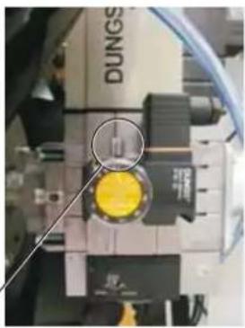
natural_image
Close-up of a mechanical device with a yellow circular component and a magnified inset showing a probe tip (no visible text or symbols)Pressure test nipple
31. Changing the gas type, CO_2 setting
Carry out the adjustments in the following sequence. At the factory, the gas combination valve has been set up for natural gas E (G20).
A) CO_2 setting at the upper load (emissions test mode)
- Release the screws on the burner hood (top).
- Remove the burner hood.
- Remove screw from the test port of the condensate trap and insert measuring device.
- Press the "Emissions test" quick start button on the AM display module or BM2 programming module.
- At full load, measure the CO_2 value, which should be 9.3% ± 0.3% for natural gas E/H/LL.
- If required, adjust the CO_2 content at the gas combination valve with a screwdriver as shown in the picture.

natural_image
Industrial equipment setup with pipes and a white cylindrical tank, no visible text or symbolsTest port on the condensate trap

31. Changing the gas type, CO_2 setting
B) CO_2 setting at the lower load (soft start)
- Restart the gas condensing boiler.
- Approx. 30 seconds after burner start, check the CO 2 content with the CO 2 measuring instrument. This should be 9.1 % ± 0.3 % for natural gas E/H/LL and can be corrected with a 2.5 mm Allen button at the gas combination valve as shown in the picture.
- Perform this adjustment at minimum load (180 sec. after burner start).
- Repeat the start phase if necessary to perform the adjustment.


natural_image
Close-up of a mechanical device with a yellow circular component and blue cables, no visible text or symbols.C) Completing the adjustments
- Shut down the boiler.
- Re-seal the test ports and check for tightness.
- Refit the burner hood.
- Screw in screws on the burner hood (top).
- Check the gas type on the type plate and change if necessary. If changed to natural gas LL, cut out label "Adjusted to LL - G25 - 20 mbar" and affix to the type plate.
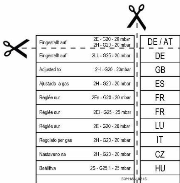
| Commissioning steps Test values or confirmation | |
| 1.) Gas type | Natural gas E/H □Natural gas LL □Wobbe index ____ kWh/m3Calorific value, heating ____ kWh/m3 |
| 2.) Gas supply pressure checked? | □ |
| 3.) Gas leak test carried out? | □ |
| 4.) Balanced flue system checked? | □ |
| 5.) Water connections checked for leaks? | □ |
| 6.) Siphon filled? | □ |
| 7.) System flushed? | □ |
| 8.) System filled and water treatment carried out in line with "Design information, water treatment"?pH value setTotal hardness set | ____ pH value____ °dH |
| 9.) No chemical additives (inhibitors, antifreeze) added? | □ |
| 10.) Boiler and system vented? | □ |
| 11.) System pressure 1.5 - 2.5 bar? | □ |
| 12.) Gas type and output entered on label? | □ |
| 13.) Function test carried out? | □ |
| 14.) Flue gas testGross flue gas temperatureVentilation air temperatureNet flue gas temperatureCarbon dioxide content (CO _2 ) or oxygen content (O _2 )Carbon monoxide content (CO) | ____ t _A [°C]____ t _A [°C]____ (t _A -t _L ) [°C]____ %____ ppm |
| 15.) Casing fitted? | □ |
| 16.) System user trained, documentation handed over? | □ |
| 17.) Commissioning confirmed? | ____ □ |
General notes
Where necessary, adapt the installation examples to the relevant building regulations and requirements in your country/region. Discuss any questions relating to the installation of inspection covers and ventilation apertures with your local flue gas inspector.
Flues inside chimney ducts must have secondary ventilation along their entire length and must terminate above the roof.
Flue gas cascades must be sized in accordance with EN 13384-2.
The requirements for installation rooms are specified in the building regulations or combustion equipment ordinances of the relevant countries. Also observe DVGW-TRGI 1986 regarding the room ventilation.

low outside temperatures, the water vapour contained in the flue gas may condense and freeze on the balanced flue. This ice may fall from the roof causing injuries or material losses. Prevent ice from falling by taking on-site measures, e.g. installing a snow guard.
Connection to a type C63 combustion air and flue system that has not been tested together with the gas combustion equipment
Original Wolf components have been optimised over many years and are designed for use with Wolf condensing boilers. If using third party equipment that is only CE-approved, the installer will be responsible for the correct sizing and perfect functioning of the system. Faults, material losses and injuries resulting from incorrect pipe lengths, excessive pressure drop, premature wear with escaping flue gas and condensate or incorrect functioning, e.g. through components working loose, are excluded from our warranty if CE-approved third-party equipment is used.
Caution
If the combustion air is drawn from the duct, the duct must be free from contamination.
Connection to the ventilation air system and the flue
The unobstructed cross-section of flues must be able to be inspected. Therefore, install an appropriate cleaning and/or inspection aperture inside the boiler room; agree suitable arrangements with your local flue gas inspector.
Flue connections are created using couplings and gaskets. Always arrange couplings against the direction of the condensate flow.

outside ducts must not be routed through other installation rooms, otherwise there would be a risk of the transfer of fire and there would be no mechanical protection.
Cafugood
mbustion air must not be drawn from chimneys previously used to carry flue gases from oil or solid fuel boilers.

the balanced flue or flue outside ducts with spacer brackets with a minimum clearance of 50 cm from the flue outlet or upstream/downstream of diverters to prevent the pipe joints being pulled apart. If this is not done, there is a danger of poisoning caused by escaping flue gas. Furthermore, boiler damage may result.

To prevent flue gas escaping, a positive pressure flue cascade is only permitted with a tested flue gas damper (part no. 2484637).

Install the ventilation air system / flue with a slope of at least 3° towards the gas condensing boiler. Spacer brackets should be fitted to secure the equipment in position. In the worst case scenario, a lesser slope of the balanced flue may lead to corrosion or operating faults.
Always
bevel or deburr trimmed flues to ensure gas-tight installation of pipe joints. Ensure that gaskets are correctly fitted. Remove all contamination prior to installation - never fit damaged parts.
davon
sizing flue systems in accordance with DIN EN 13384-2 (cascade), maintain a maximum overpressure of up to 50 Pa in the connection to the header line; this should also not be exceeded.
Caution
As protection against contamination during the building phase, we recommend using the ventilation air filter part no. 8751390. The ventilation air filter is plugged onto the air intake. Keep the door of the condensing boiler shut during the building phase. After completing the building phase, remove the filter.
34. HCM2 wiring diagram

flowchart
graph TD
    A["Fan 230 V AC"] --> B["Heating circuit"]
    B --> C["Heating circuit"]
    C --> D["Mounting plate"]
    D --> E["Pump contactor Mains contactor"]
    E --> F["Front panel"]
    F --> G["Reset"]
    G --> H["ON/OFF switch Service PCB AM/BM2 contact PCB ISM7i (optional)"]
    H --> I["Condensate pump"]
    I --> J["Boiler water temperature sensor"]
    J --> K["Water pressure sensor"]
    K --> L["Return temperature sensor"]
    L --> M["Control of variable speed heating circuit pump ZHP"]
    M --> N["Gas pressure switch"]
    N --> O["Fault message, condensate pump (jumper in plug)"]

    subgraph HCM-2
        P["X1: PE Nez L1 N N X1: NEz L1-N S X1: NEz L1-S X1: NEz L1-N X1: NEz L1-N X1: NEz L1-N X1: NEz L1-N X1: NEz L1-N X1: NEz L1-N X1: NEz L1-N X1: NEz L1-N X1: NEz L1-N X1: NEz L1-N X1: NEz L1-N X1: NEz L1-N X1: NEz L1-N X1: NO NC X6:1 X6:1<br>    end<br>    <br>    subgraph Front panel<br>        P --> Q[E1 GND a b E2 GND AF GND SF GND EBus GND"]
        Q --> R["X10:1 +5V GND +5V eBus"]
        R --> S["X9:1 +23V GND +23V eBus"]
        S --> T["X10:1 +5V GND +5V eBus"]
        T --> U["X9:1 +23V GND +23V eBus"]
        U --> V["X10:1 +5V GND +5V eBus"]
        V --> W["X9:1 +23V GND +23V eBus"]
        W --> X["X10:1 +5V GND +5V eBus"]
        X --> Y["X9:1 +23V GND +23V eBus"]
        Y --> Z["X10:1 +5V GND +5V eBus"]
        Z --> AA["X9:1 +23V GND +23V eBus"]
        AA --> AB["X10:1 +5V GND +5V eBus"]
        AB --> AC["X9:1 +23V GND +23V eBus"]
        AC --> AD["X10:1 +5V GND +5V eBus"]
        AD --> AE["X9:1 +23V GND +23V eBus"]
        AE --> AF["X10:1 +5V GND +5V eBus"]
        AF --> AG["X9:1 +23V GND +23V eBus"]
        AG --> AH["X10:1 +5V GND +5V eBus"]
        AH --> AI["X9:1 +23V GND +23V eBus"]
        AI --> AJ["X10:1 +5V GND +5V eBus"]
        AJ --> AK["X9:1 +23V GND +23V eBus"]
        AK --> AL["X10:1 +5V GND +5V eBus"]
        AL --> AM["X9:1 +23V GND +23V eBus"]
        AM --> AN["X10:1 +5V GND +5V eBus"]
        AN --> AO["X9:1 +23V GND +23V eBus"]
        AO --> AP["X10:1 +5V GND +5V eBus"]
        AP --> AQ["X9:1 +23V GND +23V eBus"]
        AQ --> AR["X10:1 +5V GND +5V eBus"]
        AR --> AS["X9:1 +23V GND +23V eBus"]
        AS --> AT["X10:1 +5V GND +5V eBus"]
        AT --> AU["X9:1 +23V GND +23V eBus"]
        AU --> AV["X10:1 +5V GND +5V eBus"]
        AV --> AW["X9:1 +23V GND +23V eBus"]
        AW --> AX["X10:1 +5V GND +5V eBus"]
        AX --> AY["X9:1 +23V GND +23V eBus"]
        AY --> AZ["X10:1 +5V GND +5V eBus"]
        AZ --> BA["X9:1 +23V GND +23V eBus"]
        BA --> BB["X10:1 +5V GND +5V eBus"]
        BB --> BC["X9:1 +23V GND +23V eBus"]
        BC --> BD["X10:1 +5V GND +5V eBus"]
        BD --> BE["X9:1 +23V GND +23V eBus"]
        BE --> BF["X10:1 +5V GND +5V eBus"]
        BF --> BG["X9:1 +23V GND +23V eBus"]
        BG --> BH["X10:1 +5V GND +5V eBus"]
        BH --> BI["X9:1 +23V GND +23V eBus"]
        BI --> BJ["X10:1 +5V GND +5V eBus"]
        BJ --> BK["X9:1 +23V GND +23V eBus"]
        BK --> BL["X10:1 +5V GND +5V eBus"]
        BL --> BM["X9:1 +23V GND +23V eBus"]
        BM --> BN["X10:1 +5V GND +5V eBus"]
        BN --> BO["X9:1 +23V GND +23V eBus"]
        BO --> BP["X10:1 +5V GND +5V eBus"]
        AP --> BQ["E Bus X53 8 9 10 1 2 4 6 8 9 10 1 2 4 6 8 9 10 1 2 4 6 8 9 10 1 2 4 6 8 9 10 1 2 4 6 8 9 10 1 2 4 6 8 9 10 1 2 4 6 8 9 10 1"] & AD["Front panel"]
34. GBC-P wiring diagram

flowchart
graph TD
    A["230V L 230V N FE X1 +23V CC TX CC RX GND Res."] --> B["GBC-p"]
    B --> C["V2 N 9 V2 L V1 L V1 N Zünd. N Vent. N Vent. L Zünd. L X2 Ion. 1"]
    B --> D["X3:1"]
    B --> E["X4"]
    B --> F["Gas combination valve"]
    B --> G["Monitoring electrode"]
    B --> H["Gas burner"]
    B --> I["Ignition electrodes"]
    B --> J["Connection for safety circuit provided by operator"]
    B --> K["Flue gas pressure switch"]
    B --> L["Fan PWM signal"]
    B --> M["eHLSC sensor 1"]
    B --> N["eHLSC sensor 2"]
    B --> O["HLSC"]
    B --> P["Flue gas temperature sensor"]
General notes
Never remove, bypass or otherwise disable any safety or monitoring equipment. The boiler must only be operated if it is in perfect technical condition. Any faults and damage with potential impact on safety and which might limit the safe use of the equipment must be remedied immediately by a qualified contractor. Only replace faulty components and equipment with original Wolf spare parts.
Faults and warnings are shown in plain text on the display of the control accessories – AM display module or BM2 programming module – and correspond to the messages listed in the following tables.
A warning/fault symbol on the display (symbol: triangle with exclamation mark) indicates an active warning or fault message. A lock symbol (symbol: lock) indicates that the current fault message has caused a lockout of the boiler. The duration of the current message is also shown.
Caution Warning messages do not need to be acknowledged and do not lead directly to the boiler being switched OFF. However, the causes of the warnings can lead to malfunctions of the boiler / system or faults and should therefore be repaired by an expert.
Caution Faults must only be repaired by qualified expert personnel. If a lockout fault message is acknowledged several times without fixing the cause of the problem, this can lead to damage to parts or to the system.
The control unit automatically acknowledges faults such as defective temperature sensors or other sensors if the part concerned has been replaced and plausible test values have been supplied.


Procedure for faults:
- Read fault message.
- Determine cause of fault using the table below and remedy it.
- Reset fault with "Fault reset" button or in the contractor menu under "Acknowledge fault". If the fault message cannot be acknowledged, high temperatures at the heat exchanger might be preventing a reset.
- Check that the system is functioning correctly.
Procedure for warnings:
- Read warning message.
- Determine cause of warning using the table below and remedy it.
- With warnings, there is no need for fault acknowledgement.
- Check that the system is functioning correctly.
Fault history:
A fault history can be called up and the most recent fault messages displayed in the contractor menu of the AM display module or BM2 programming module.

Fault
The following faults are in the system:
| Fault code | Fault Cause Remedy | ||
| 1 HLSC excess temp. The high limit safety cut-out (thermostat) has respondedThe boiler water temperature has exceeded 107 °C | Test heating circuit pump, vent system, press reset, clean heat exchanger | ||
| 2 TL excess temp. One of the temperature sensors eHLSC1 or eHLSC2 has exceeded the high limit safety cut-out limit (105 °C) | Test heating circuit pump, test sensors, vent system, press reset, clean heat exchanger | ||
| 3 eHLSC drift Temperature difference between temperature sensors eHLSC1 and eHLSC2 > 6 °C | Test sensors, test heating circuit pump, vent system, press reset, clean heat exchanger | ||
| 4 No flame At burner start, no flame at the end of the safety time, monitoring electrode faulty, ignition electrode faulty, ignition transformer faulty | Test monitoring electrode, ignition electrode and ignition transformer, press reset, check gas pressure | ||
| 5 Flame failure Flame failure during operation, monitoring electrode faulty, flue gas path blocked, condensate drain blocked | Test monitoring electrode, press reset, test flue system, test condensate drain | ||
| 6 TC excess temp. One of the temperature sensors eHLSC1 or eHLSC2 has exceeded the limit of the temperature limiter (97 °C) | Test heating circuit pump, vent system, test sensors, press reset, clean heat exchanger | ||
| 7 TL flue excess temp. The flue gas temperature has exceeded the limit of the TBA shutdown temperature | Clean heat exchanger, test sensors, check flue system | ||
| 8 Flue gas damper does not switch | Flue gas damper contact (E1) closes or does not open on demand; output A1 does not activate flue gas damper | Check flue gas damper and wiring, check settings HG13 and HG14 | |
| 9 Fault code unknown This fault is not known in this software Check software version of the PCBs | |||
| 10 eHLSC sensor faulty Temperature sensor eHLSC1, eHLSC2 or sensor lead has short circuit or break | Check sensor and lead | ||
| 11 Flame pretence | A flame is recognised before the burner starts | Press reset, test monitoring electrode | |
| 12 Boiler sensor faulty | Boiler sensor > 105 °C, boiler sensor or sensor lead has short circuit or break | Check sensor and lead | |
| 13 FlueG sensor faulty | Flue gas sensor or sensor lead has short circuit or break | Check sensor and lead | |
| 14 DHW sensor faulty | DHW sensor (cylinder sensor) or sensor lead has short circuit or break | Check sensor and lead | |
| 15 Outside temperature sensor faulty | Outside temperature sensor or sensor lead has short circuit or break | Check sensor and lead | |
| 16 Rtn sensor faulty Return sensor | or sensor lead has short circuit or break | Check sensor and lead | |
| 18 Ext. safety circuit | The contact for the external safety circuit has responded (maximum pressure limiter, low water indicator, etc.) | Press reset, repair fault | |
| 20 GCV relay test | The internal relay test failed | Press reset, replace burner control unit | |
| 24 Fan speed < | The fan does not reach the set speed | Test the fan's PWM and power cable, test fan, press reset | |
| 26 Fan speed > The fan does not stop Test the fan's PWM and power cable, test fan, press reset, test flue system for strong draught | |||
| 30 CRC burner control unit The EEPROM record is invalid Switch the power supply OFF and ON. If unsuccessful, replace the burner control unit. | |||
| 32 Fault in 23 V AC supply 23 V AC supply outside the permissible range (e.g. short circuit) Switch the power supply OFF and ON. If unsuccessful, replace the control PCB. | |||
| 35 BBC missing Boiler chip card has been removed or not correctly inserted Refit the correct boiler chip card | |||
| 36 BCC faulty Faulty boiler chip card Replace boiler chip card | |||
| 37 Incorrect BCC The boiler chip card is incompatible with the control PCB Refit the correct boiler chip card | |||
| 38 BCC update required Boiler chip card fault, PCB requires a new boiler chip card (replacement) Reinsert boiler chip card, replace boiler chip card | |||
| 39 BCC system error Faulty boiler chip card Replace boiler chip card | |||
| 41 Flow monitoring Return temperature > flow temperature Vent system, check heating circuit pump, test flow and return pipe connection | |||
| 42 Condensate pump is not pumping anything out Faulty condensate pump, drain line blocked, no power supply to pump Check pump, check drain line, check mains plug and fuse | |||
| 44 Flue gas pressure switch Flue system back pressure too high Heat exchanger contaminated, check flue system, test flue gas damper, press reset | |||
| 52 Max. cylinder heating time Cylinder heating takes longer than permitted Test DHW sensor (cylinder sensor) and sensor lead, press reset | |||
| 53 IO control deviatn Wind recognition, severe storm, insufficient ionisation signal during operation, burner contaminated Test monitoring electrode, check flue system, press reset, clean burner | |||
| 60 Siphon backpressure Siphon or flue system is blocked Clean siphon; test flue system, ventilation air, gas supply pressure (flow pressure) and monitoring electrode | |||
| 78 Header sensor fault Faulty sensor or lead Check sensor and lead; replace if required | |||
| 90 BCU comm error Emergency stop via ChipCom, faulty communication between control PCB and burner control unit Switch the power supply OFF and ON. If unsuccessful, call in a specialist contractor. | |||
| 95 Prog. mode Burner control unit is controlled by PC No action | |||
| 96 Reset Reset button pressed too often Switch the power supply OFF and ON. If unsuccessful, call in a specialist contractor | |||
| 98 Flame amplifier Internal burner control unit fault Monitoring electrode short circuit Press the reset button, and switch the power supply OFF and ON. If unsuccessful, call in a specialist contractor, test monitoring electrode | |||
| 99 Burner control unit system fault Internal burner control unit fault Switch the power supply OFF and ON. If unsuccessful, call in a specialist contractor. | |||
35. Troubleshooting
| Fault code | Fault Cause Remedy | ||
| 107 HC | pressure Water pressure too low, water pressure too high | Test system pressure, test cable, press reset, test water pressure sensor | |
Button
| Button | |
| BCC Boiler chip card | |
| CRC Cyclic redundancy check | |
| EEPROM Rewritable memory | |
| BCU Burner control unit | |
| GCV Gas combination valve | |
| IO Ionisation signal | |
| HLSC High limit safety cut-out | |
| eHLSC Electronic high limit safety cut-out | |
| TL Temperature limiter | |
| TBA Flue gas high limit safety cut-out | |
| TW Temperature limiter | |
Warning messages
The following warnings are in the system:
| Number | Fault Description Cause and remedy | ||
| 1 BCU | replaced The control PCB has | detected that the burnercontrol unit has been replaced | Insert boiler chip card thatcorresponds to appliance output; ifnecessary,reinsert boiler chip card |
| 2 HC | pressure The water pressure has | fallen below thewarning limit | Check the system pressure,test sensors |
| 3 Parameter changed Another boiler chip card has been inserted Make sure that the correct boilerchip card has been inserted,if necessary,reinsert boiler chip card | |||
| 4 No | flame At the last attempt to start the burner, noflame was detected | Wait for another start attempt,test ignition electrode and ignitiontransformer,test monitoringelectrode,test gas connectionpressure | |
| 5 Flame failure duringstabilisation timeFlame failure after safety time | Flame failure during operation Monitoring electrode faulty, fluegas path blocked, condensatedrain blocked,test gas connectionpressure | ||
| 24 Speed below or above limit The fan does not reach the set speed,ordoes not stop | Test flue system,test the fan's PWMand power cable | ||
| 43 | Many burner starts | Number of burner starts too high | Too little heat is being drawn off,tolittle throughput,demand too high |
NTC sensor resistances
Boiler sensor, cylinder sensor, outside temperature sensor, return sensor, eHLSC sensor, header sensor
| Temp. °C | Resist. Ω | Temp. °C | Resist. Ω | Temp. °C | Resist. Ω | Temp. °C | Resist. Ω |
| -21 513 | 93 14 8233 | 49 1870 84 | 552 | ||||
| -20 484 | 87 15 7857 | 50 1800 85 | 535 | ||||
| -19 457 | 62 16 7501 | 51 1733 86 | 519 | ||||
| -18 432 | 07 17 7162 | 52 1669 87 | 503 | ||||
| -17 408 | 10 18 6841 | 53 1608 88 | 487 | ||||
| -16 385 | 60 19 6536 | 54 1549 89 | 472 | ||||
| -15 364 | 47 20 6247 | 55 1493 90 | 458 | ||||
| -14 344 | 63 21 5972 | 56 1438 91 | 444 | ||||
| -13 325 | 99 22 5710 | 57 1387 92 | 431 | ||||
| -12 308 | 46 23 5461 | 58 1337 93 | 418 | ||||
| -11 | 29198 24 | 5225 59 12 | 89 94 406 | ||||
| -10 276 | 48 25 5000 | 60 1244 95 | 393 | ||||
| -9 | 26189 26 | 4786 61 12 | 200 96 382 | ||||
| -8 | 24816 | 27 | 4582 | 62 | 1158 | 97 | 371 |
| -7 | 23523 | 28 | 4388 | 63 | 1117 | 98 | 360 |
| -6 | 22305 29 | 4204 64 10 | 78 99 349 | ||||
| -5 | 21157 | 30 | 4028 | 65 | 1041 | 100 | 339 |
| -4 | 20075 31 | 3860 66 10 | 05 | 101 330 | |||
| -3 | 19054 32 | 3701 67 | 971 102 | 320 | |||
| -2 | 18091 | 33 | 3549 | 68 | 938 | 103 | 311 |
| -1 | 17183 34 | 3403 69 | 906 104 | 302 | |||
| 0 | 16325 35 | 3265 70 | 876 105 | 294 | |||
| 1 | 15515 36 | 3133 71 | 846 106 | 285 | |||
| 2 | 14750 37 | 3007 72 | 818 107 | 277 | |||
| 3 | 14027 38 | 2887 73 | 791 108 | 270 | |||
| 4 | 13344 39 | 2772 74 | 765 109 | 262 | |||
| 5 | 12697 | 40 | 2662 | 75 | 740 | 110 | 255 |
| 6 | 12086 | 41 | 2558 | 76 | 716 | 111 | 248 |
| 7 | 11508 | 42 | 2458 | 77 | 693 | 112 | 241 |
| 8 | 10961 | 43 | 2362 | 78 | 670 | 113 | 235 |
| 9 | 10442 | 44 | 2271 | 79 | 670 | 114 | 228 |
| 10 | 9952 | 45 | 2183 | 80 | 628 | 115 | 222 |
| 11 | 9487 | 46 | 2100 | 81 | 608 | 116 | 216 |
| 12 | 9046 | 47 | 2020 | 82 | 589 | 117 | 211 |
| 13 | 8629 | 48 | 1944 | 83 | 570 | 118 | 205 |
38. Technical parameters according to EU regulation no. 813/2013
| Type MGK-2-390 | |||
| Condensing boiler [yes/no] yes | |||
| Low temperature boiler (**) [yes/no] no | |||
| B11 boiler [yes/no] no | |||
| Cogeneration space heater [yes/no] no | |||
| If yes, equipped with a supplementary heater | [yes/no] - | ||
| Combination heater [yes/no] no | |||
| Item Symbol Unit | |||
| Rated heat output P | rated | kW | 367 |
| Useful heat output at rated heat output and high-temperature regime (*) | P_4 | kW | 366,7 |
| Useful heat output at 30% of rated heat output and low-temperature regime (**) | P_1 | kW | 121,6 |
| Auxiliary electricity consumption at full load | elmax | kW | 0,410 |
| Auxiliary electricity consumption at part load | elmin | kW | 0,042 |
| Auxiliary electricity consumption in standby mode | P_SB | kW | 0,011 |
| Seasonal space heating energy efficiency | n_s | % | 93 |
| Useful efficiency at rated heat output and high-temperature regime (*) | n_4 | % | 88,9 |
| Useful efficiency at 30% of rated heat output and low-temperature regime (**) | n_1 | % | 97,0 |
| Standby heat loss | P_city | kW | 0,401 |
| Ignition burner power consumption | P_ing | kW | 0,000 |
| Emissions of nitrogen oxides | NO_x | mg/kWh | 34 |
| Contact details | Wolf GmbH, Industriestraße 1, D-84048 Mainburg | ||
(*) High-temperature regime means 60°C return temperature at heater inlet and 80°C feed temperature at heater outlet.
(**) Low temperature means for condensing boilers 30°C, for low-temperature boilers 37°C and for other heaters 50°C return temperature (at heater inlet).
DECLARATION OF CONFORMITY
(to ISO/IEC 17050-1)
Number: 3063772
Issued by: Wolf GmbH
Address: Industriestrasse 1, D-84048 Mainburg
Product: MGK-2 gas condensing boiler
The product described above conforms to the requirements specified in the following documents:
§ 6, 1. BlmSchV, 26/01/2010
DIN EN 437, 09/2009
DIN EN 483, 06/2000
DIN EN 677, 08/1998
DIN EN 60335-1, 10/2012
DIN EN 60335-2-102, 07/2010
DIN EN 55014-1, 05/2012
In accordance with the following Directives
2009/142/EC (Gas Appliances Directive)
2004/108//EC (EMC Directive)
2006/95/EC (Low Voltage Directive)
2009/125/EG (ErP Directive)
2011/65/EU (RoHS Directive)
this product is identified as follows:

Mainburg, 15/07/2015

natural_image
Abstract curved line drawing with no text or symbolsGerdewan Jacobs
Technical Director

Klaus Grabmaier
Product approval
- Installation instructions for contractors
- Gas condensing boilers
- Installation
- Control unit
- Cascade operation
- Commissioning
- Specification
- Information about this document
- Other applicable documents
- Safekeeping of these documents
- Obligations of the operator
- Applicability of these instructions
- Acceptance
- Information about disposal
- MGK-2 standard delivery
- Safety instructions
- Working on the system
- Danger if you smell gas
- Danger if you smell flue gas
- Inspection and maintenance
- Information about disposal:
- Dimensions
- Specification
- Casing
- Remove burner hood
- Open side casing
- Standards and regulations
- The following local regulations must be complied with for installation and operation:
- The following general regulations, rules and guidelines must be observed for installation in particular:
- The following also apply to installation and operation in Germany:
- For installation and operation in Austria, the following apply:
- For installation in Switzerland, the following apply:
- Handling / Installation instructions
- Installation instructions
- Installation instructions
- Caution
- Minimum clearances:
- Equipment level to DIN EN 12828 for MGK-2
- Boiler system pipework
- Selection of circulation pumps
- Gas connection
- Fitting the siphons
- Condensate connection:
- Install siphons:
- Installing the neutralising system with booster pump
- Function check
- Neutralising system / condensate pump (accessories)
- Servicing the neutralising system
- Fill with fresh granulate up to the fill level indicated by the label.
- Disposal
- Condensate lifting system (accessory)
- Please note:
- Air/flue gas routing
- Comments:
- Note:
- Electrical connection
- Boiler connection (230 V/400 V):
- Installation information, electrical connection, mains
- Installation information, electrical connection, heating circuit pump
- Connection output A1 (230 V AC; max. 1.5 A) \*
- Connection output Z1 (230 V AC; max. 1.5 A) \*
- Connection output primary pump (230 V AC; max. 1.5 A)
- Changing the fuse (HCM-2)
- Changing the fuse (booster fuse)
- Low voltage boiler connection:
- Connection input E1
- Connection input E2
- Connection, outside temperature sensor
- Connection, digital Wolf control accessories (e.g. TM2, MM, KM, SM1, SM2)
- Installing the electrical connection of the external safety circuit
- Display / programming module / installation
- AM BM2
- Specification:
- NB:
- Overview AM
- AM display module menu structure
- Heating appliance
- Status
- Notification
- Main menu
- Displays
- Default settings
- Emissions test
- Contractor
- Parameter HG01
- Parameter HG02
- Parameter HG03
- Parameter HG04
- Parameter description
- Parameter HG07
- Parameter HG08
- Parameter HG09
- Parameter HG10
- Parameter HG13
- Function input E1
- Parameter HG14
- Parameter HG15
- Parameter HG16
- Parameter HG17
- Parameter HG19
- Parameter HG20
- Parameter HG21
- Parameter HG22
- Parameter HG25
- Parameter HG33
- Parameter HG34
- Parameter HG37
- Parameter HG38
- Parameter HG39
- Parameter HG40
- System configuration 01
- Direct heating circuit on the boiler + optional further mixer circuits via mixer modules (factory setting)
- System configuration 02
- One or more mixer circuits via mixer modules (no direct heating circuit on the boiler)
- System configuration 11
- Low loss header with header sensor
- Plate heat exchanger as system separation
- System configuration 51
- BMS burner output
- System configuration 52
- BMS set boiler temperature
- System configuration 60
- Cascade for multi boiler systems (setting automatic when cascade module is connected)
- Parameter HG41
- Parameter HG42
- Parameter HG46
- Flue gas damper power supply
- Damper function test
- Cascade operation
- Cascade module setting
- Pump speed setting
- Setting the eBUS address in cascade mode
- Flue gas damper installation
- Filling / draining the heating system
- Filling the heating system
- Draining the heating system
- Energy savings
- Checking the gas supply pressure
- Countries, gas categories and connection pressures
- Re-seal the test nipple with the plug.
- Changing the gas type, CO_2 setting
- A) CO_2 setting at the upper load (emissions test mode)
- B) CO_2 setting at the lower load (soft start)
- C) Completing the adjustments
- General notes
- Connection to the ventilation air system and the flue
- HCM2 wiring diagram
- GBC-P wiring diagram
- Procedure for faults:
- Procedure for warnings:
- Fault history:
- Troubleshooting
- Warning messages
- NTC sensor resistances
- Technical parameters according to EU regulation no. 813/2013
- DECLARATION OF CONFORMITY
Brand : WOLF
Model : MGK-2-470
Category : Central heating boiler