
P.I.P.-ATN - Uncategorized CROWN - Free user manual and instructions
Find the device manual for free P.I.P.-ATN CROWN in PDF.


| Product Type | Programmable Input Processor (P.I.P.) module for Crown Com-Tech® and Macro-Tech® series amplifiers |
| Brand | Crown (also exported as Amcron®) |
| Model | P.I.P.-ATN |
| Dimensions | 16.2 x 4.8 x 9.8 cm (638 x 178 x 378 in) |
| Weight | 12 ounces (340 grams) |
| Input Impedance | 20 kohm nominal |
| Maximum Input Level | +20 dB at 1 kHz |
| Nominal Gain | Unity |
| Frequency Response | ±1 dB from 20 Hz to 20 kHz (filters off) |
| Signal-to-Noise Ratio | Better than -85 dB (equivalent input noise) from 20 Hz to 20 kHz |
| Common Mode Rejection | Better than 60 dB at 1 kHz |
| Crosstalk | -82 dB at 1 kHz |
| Input Attenuator | 32-step calibrated attenuator per channel: 1 dB steps (0-16 dB), 2 dB steps (18-24 dB), 3 dB steps (27-36 dB), 4 dB steps (40-60 dB), and infinite |
| Subsonic/Bass Filter | 18 dB/octave Butterworth high-pass filter, selectable roll-off at 50 Hz, 100 Hz, 300 Hz, or Flat |
| Constant-Directivity Horn EQ | 6 dB/octave shelving network, 3 dB rise at 3.2 kHz, 12.5 dB peak at 24 kHz; switchable on/off per channel |
| RFI Filter | Permanent 12 dB/octave Bessel low-pass filter, -3 dB at 33 kHz |
| Input Connectors | Quick-disconnect barrier blocks (balanced inputs with 1:1 isolation transformers) |
| Recommended Source Impedance | 10 kohm or less |
| Installation | Quick install in rear panel of Crown Com-Tech® or Macro-Tech® amplifiers; requires Phillips screwdriver |
| Safety Note | Turn off amplifier and disconnect AC power before installation; avoid circuit tampering |
| Warranty | Voided by unauthorized modifications |
Frequently Asked Questions - P.I.P.-ATN CROWN
User questions about P.I.P.-ATN CROWN
0 question about this device. Answer the ones you know or ask your own.
Ask a new question about this device
Download the instructions for your Uncategorized in PDF format for free! Find your manual P.I.P.-ATN - CROWN and take your electronic device back in hand. On this page are published all the documents necessary for the use of your device. P.I.P.-ATN by CROWN.
USER MANUAL P.I.P.-ATN CROWN
natural_image
Simple line drawing of a crown inside a rounded square frame (no text or symbols)P.I.P.-ATN
PROGRAMMABLE INPUT PROCESSOR
OWNER'S MANUAL
Exported to select countries as Amcron®
©1994 by CROWN INTERNATIONAL, INC.
P.O. Box 1000, Elkhart, IN 46515
Telephone: 219-294-8000
Amcron ® , Crown ® , Com-Tech ® , Macro-Tech ® and P.I.P. ® are registered trademarks of Crown International, Inc.
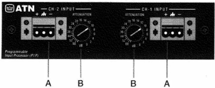
Fig. 1.1 Front View

Thank you for purchasing the Crown P.I.P.-ATN accessory. P.I.P. ® modules are designed to quickly install in the rear panel of Crown Com-Tech ® or Macro-Tech ® series amplifiers. P.I.P. stands for “Programmable Input Processor.” Their versatile features expand the capabilities of your amplifier and enable you to customize it for your particular needs.
You should find these items when you unpack:
P.I.P.-ATN Module
Two 8-32 Phillips Machine Screws
Two Lock Washers
Two Quick-Disconnect Barrier Blocks
This Owner's Manual
Features
☐ Balanced inputs with 1:1 isolation transformers to help keep the input noise-free.
☐ RFI filter which attenuates unwanted ultrasonic frequencies. The RFI filter is a 12 dB/octave (2nd order), Bessel-tuned low-pass filter with a 3 dB roll-off point at 33 kHz.
☐ Switchable subsonic/bass filter with 50, 100 or 300 Hz roll-off.
☐ Constant-directivity horn equalization network which can be switched on or off.
☐ Calibrated 32-step attenuators give precise level control of the input signal.
☐ Quick-connect barrier block connectors provide greater wiring flexibility and make installation easier.
Facilities
A. Balanced Input
With these special quick-connect barrier-block connectors (Figure 1.1), it's quick and easy to attach each input cable with just three screws. Once the cable is attached, the connector can be quickly unplugged and, if desired, moved to a different amplifier.
B. Input Attenuator
A calibrated precision attenuator (Figure 1.1) provides accurate level adjustment. It has 32 detented steps which "click" into place for ease of use. Positions 1–17 advance in 1 dB increments. Positions 18–21 advance in 2 dB increments. Positions 22–25 advance in 3 dB increments. Positions 26–31 advance in 4 dB increments. The last step is infinite attenuation.
C. Subsonic/Bass Switch
A 4-position sliding switch for each channel(Fig. 1.2) controls the subsonic/bass filter. This filter is an 18 dB/octave (3rd order) Butterworth high-pass filter which can be selected to attenuate low frequencies below 50 Hz, 100 Hz or 300 Hz. It can also be switched off (Flat). A label on the side of each switch identifies the switch settings.
D. Constant-Directivity Horn Equalization Jumper
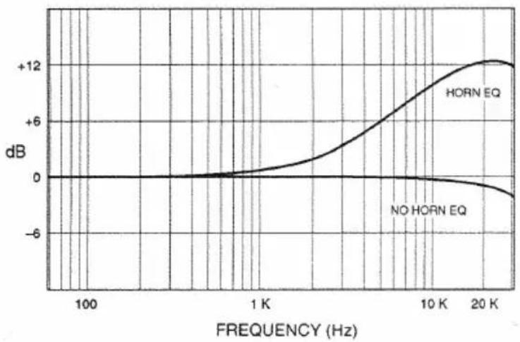
A jumper is provided for each channel (Figure 1.2) to enable/disable the constant-directivity horn equalization. The jumper for channel 1 (J1) is shown in the "OFF" position while the jumper for channel 2 (J2) is shown in the "ON" position. The constant directivity horn equalization is a 6 dB/octave shelving network with a 3 dB rise at 3.2 kHz and a peak boost of 12.5 dB at 24 kHz.
2 Installation
Before installing this P.I.P. module, you'll want to configure it.
Note: The RFI filter is always on and cannot be switched off.
- Adjust the constant-directivity equalization jumper of each channel to be either "on" or "off" (see Figure 1.2). Figure 2.1 shows the frequency response through the P.I.P.-ATN when this filter is on.
- Select the desired position for the Subsonic/Bass filter switch for each channel. Pushing the switch all the way forward toward the front of the module switches the filter off ("Flat"). A label is affixed to the inside of the switch to show what the positions do (see also Figure 1.2). Figure 2.2 shows the frequency response through the P.I.P.-ATN when this filter is set in each of its four modes (Flat, 50 Hz, 100 Hz, 300 Hz).
Now you are ready to install the P.I.P. in the amplifier.
IMPORTANT: Before connecting this or any P.I.P. to your amplifier, it is important to turn its level controls down, turn it off and remove the AC power from it. Even though the amplifier is off, there could still be enough energy in the circuitry to cause electric shock.
You need only a phillips screwdriver to connect your P.I.P.-ATN.
- If present, remove the cover over the level controls. Turn down the level controls (full counterclockwise), turn off the amplifier and unplug it from the AC power source.
- Remove the existing P.I.P. module or panel (two screws) and pull straight out with firm pressure.
- Align the edge connector of the P.I.P. circuit board into the P.I.P. card rails (Figure 2.3).
- Firmly push the P.I.P.-ATN all the way in until it is seated against the mounting bracket.
- Secure it with the two screws and lock washers provided. The lock washers are important because they bond the P.I.P. to the chassis ground of the amp.
- Turn the input attenuators to zero attenuation (full clockwise).
- Plug in the amplifier and turn it on. Adjust the level controls of the amplifier to the maximum desired setting. If a cover panel was installed over the level controls, reinstall it.
- Make minor level adjustments using the precision attenuator controls on the P.I.P.-ATN.
If you do not want to use the attenuator controls on the P.I.P., you can skip steps 6–8 and turn them to zero. In this case use only the level controls of the amplifier to adjust the signal level.
Do not tamper with the circuitry. Circuit changes made by unauthorized personnel, or unauthorized circuit modifications, void the warranty.
Remember: Crown is not liable for damage resulting from overdriven components in your sound system.
Fig. 2.1 Constant-Directivity Horn Equalization (with RFI filter)
line
| FREQUENCY (Hz) | HORN EQ | NO HORN EQ | | -------------- | ------- | ---------- | | 100 | 0 | 0 | | 1K | 0 | 0 | | 10K | +12 | -6 | | 20K | +12 | -6 |Fig. 2.2 Subsonic/Bass Filter Settings

line
| FREQUENCY (Hz) | FLAT (dB) | 50 Hz (dB) | 100 Hz (dB) | 300 Hz (dB) | | -------------- | --------- | ---------- | ----------- | ----------- | | 10 | -12 | -18 | -6 | -12 | | 100 | -6 | -12 | -6 | -12 | | 1 K | 0 | 0 | 0 | 0 |
Fig. 2.3 P.I.P. Installation

crown
P.I.P.-ATN
P.I.P.-ATN

crown
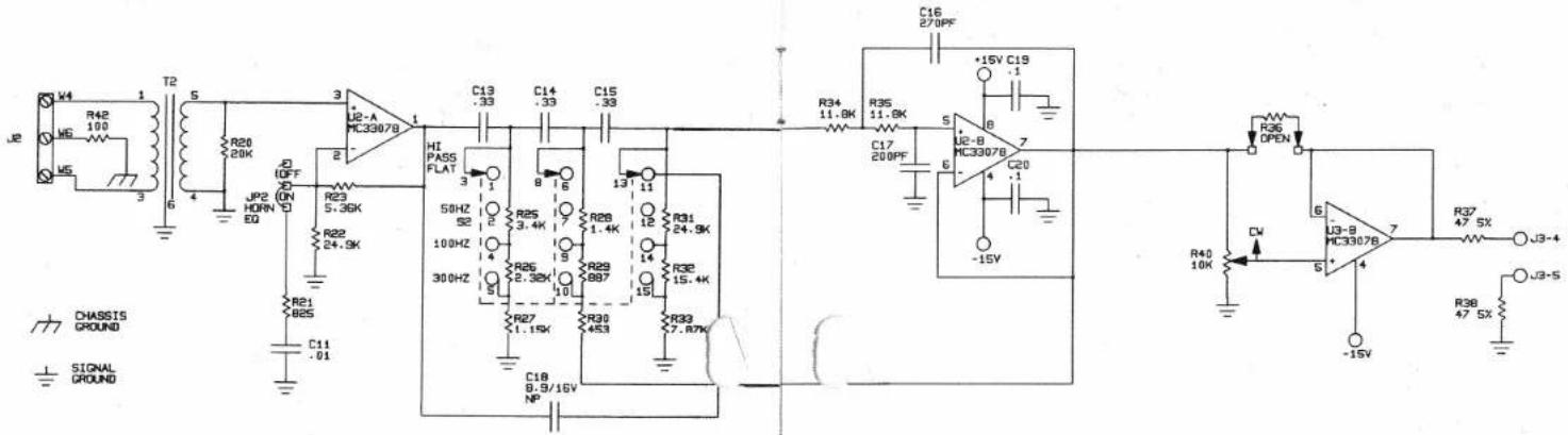

Only one channel shown
Schematic
J0362-4 rev. B
Notes:
- All resistors are in ohms, 0.25W, 1%, unless specified otherwise.
- All capacitors are in microfarads unless specified otherwise.
Schematic
3 Specifications
Signal to Noise: Better than -85 dB (equivalent input noise) from 20 Hz to 20 kHz.
Common Mode Rejection: Better than 60 dB at 1 kHz.
Crosstalk: -82 dB at 1 kHz.
Input Impedance: Nominally 20 kohm.
Recommended Source Impedance: 10 kohm or less.
Maximum Input Level: +20 dB at 1 kHz.
Nominal Gain: Unity.
Frequency Response: ±1 dB from 20 Hz to 20 kHz when filters set flat and horn equalization off. High-pass (subsonic/bass) filter has selectable -3
dB roll-off points of 50, 100 or 300 Hz (see Figure 2.2). Constant-directivity horn equalization network has 3 dB rise at 3.2 kHz with 12.5 dB peak at 24 kHz (see Figure 3.1). Both these filters can be switched off if desired.
A permanent RFI filter with a -3 dB roll-off at 33 kHz also affects the response.
Attenuation: 32-step attenuator for each channel:
| Attenuation | Step Size |
| 0 – 16 dB | 1 dB |
| 18 – 24 dB | 2 dB |
| 27 – 36 dB | 3 dB |
| 40 – 60 dB | 4 dB |
| ∞ | Infinite |
Dimensions: 638 × 178 × 378 in (16.2 x 4.8 x 9.8 cm).
Weight: 12 ounces (340 grams).
Note: All specifications referenced to a 0.775 V input signal.

crown®
THE PROFESSIONAL AUDIO DIVISION OF CROWN INTERNATIONAL, INC.
57620 C.R. 105, Elkhart, Indiana 46517 USA
TEL: 800-342-6939 (USA) or 219-294-8200 FAX: 219-294-8301
Brand : CROWN
Model : P.I.P.-ATN
Category : Uncategorized