
MultiPlus 500 ВA - Battery charger VICTRON ENERGY - Free user manual and instructions
Find the device manual for free MultiPlus 500 ВA VICTRON ENERGY in PDF.


| Product Type | Inverter/Charger (MultiPlus) |
| Model | MultiPlus 12/500/20-120V |
| Brand | Victron Energy |
| Input Voltage Range (AC) | 95 - 140 VAC |
| Input Frequency Range | 45 - 65 Hz |
| Output Voltage (Inverter) | 120 VAC ±2% |
| Output Frequency | 60 Hz ±0.1% (adjustable to 50 Hz) |
| Continuous Output Power at 25°C | 430 W (500 VA) |
| Peak Power | 900 W |
| Maximum Efficiency | 90% |
| Zero-Load Power | 6 W (2 W in search mode) |
| Battery Voltage | 12 VDC |
| Charge Current (House Battery) | 20 A |
| Charge Current (Starter Battery) | 1 A |
| Charge Algorithm | 4-stage adaptive (Bulk, Absorption, Float, Storage) with BatterySafe mode |
| Battery Types Supported | Gel, AGM, LiFePO4, tubular plate (selectable via DIP switches) |
| Transfer Switch Rating | 16 A |
| Protections | Output short circuit, overload, battery over/under voltage, over temperature, AC ripple, backfeed |
| Programmable Relay | Yes (alarm, generator start, etc.) |
| Operating Temperature | -40 to +65°C |
| Cooling | Fan assisted |
| Enclosure Material & Color | Steel/ABS, blue RAL 5012 |
| Protection Category | IP21 |
| Weight | 4.4 kg |
| Dimensions (H x W x D) | 311 x 182 x 100 mm |
| Safety Standards | EN-IEC 60335-1, EN-IEC 60335-2-29, EN 62109-1 |
| Parallel Capability | Up to 6 units in parallel |
| Three-Phase Capability | Yes (wye config) |
| Remote Control Options | 3-position switch or Digital Multi Control panel |
| Temperature Sensor | Included for temperature-compensated charging |
Frequently Asked Questions - MultiPlus 500 ВA VICTRON ENERGY
User questions about MultiPlus 500 ВA VICTRON ENERGY
0 question about this device. Answer the ones you know or ask your own.
Ask a new question about this device
Download the instructions for your Battery charger in PDF format for free! Find your manual MultiPlus 500 ВA - VICTRON ENERGY and take your electronic device back in hand. On this page are published all the documents necessary for the use of your device. MultiPlus 500 ВA by VICTRON ENERGY.
USER MANUAL MultiPlus 500 ВA VICTRON ENERGY
12/500/20-120V and 12/1200/50-120V
Rev 00 - 10/2023
Table of Contents
1. Safety instructions .... 2
1.1.General 2
1.2. Installation 2
1.3. Transport and storage 2
1.4. Symbols on enclosure 3
2. Description 4
2.1.General 4
2.2.Battery charger 4
3. Operation 6
3.1. On/Off/Charger-only switch 6
3.2. LED indications 6
3.3. Remote control 7
3.4. Maintenance 7
4. Installation 8
4.1. location 9
4.2. Battery connection 9
4.3. AC connection 10
4.4. Optional connections ...... 10
4.4.1.Second battery 10
4.4.2. Temperature sensor 10
4.4.3. Remote control 10
4.4.4. Programmable relay 10
4.4.5. Parallel connection 11
4.4.6. Three-phase connection 11
5. Configuration 13
5.1. Standard settings: ready for use 13
5.2. Explanations of settings 13
5.3. Configuration by computer 15
5.4. Configuration by DIP switches 16
6. Troubleshooting 18
7. Technical data 20
7.1. Technical specifications ...... 20
7.2. Connection overview 22
7.3. Internal wiring diagram 23
7.4. Four-stage charge algorithm 24
7.5. Temperature compensation charge chart 25
7.6. Dimension drawings 26
This manual is also available in HTML5.
1. Safety instructions
Please familiarise yourself with the safety features and instructions by first reading the documentation supplied with this product before using the equipment. This product has been designed and tested in accordance with international standards. The equipment must be used exclusively for the purpose for which it was designed
1.1. General
Please read the documentation supplied with this product first so that you are familiar with the safety signs and directions before using the product.
This product is designed and tested in accordance with international standards. The equipment should be used for the designated application only.

WARNING - These servicing instructions are for use by qualified personnel only. To reduce the risk of electric shock, do not perform any servicing other than that specified in the operating instructions unless you are qualified to do so.

WARNING - The product is used in combination with a permanent energy source (battery). Even if the equipment is switched off, a dangerous electrical voltage can occur at the input and/or output terminals. Always switch the AC power off and disconnect the battery before performing maintenance.
The product contains no internal user-serviceable parts. Do not open the enclosure, and do not put the product into operation unless all panels are fitted. All maintenance should be performed by qualified personnel. Internal fuses are not user-replaceable. A unit with suspected blown fuses should be taken to an authorised service centre for evaluation.
Never use the product at sites where gas or dust explosions could occur. Refer to the specifications provided by the manufacturer of the battery to ensure that the battery is suitable for use with this product. The battery manufacturer's safety instructions should always be observed.
Never try to charge non-rechargeable - or frozen batteries.
This appliance is not intended for use by persons (including children) with reduced physical, sensory or mental capabilities or lack of experience and knowledge unless they have been given supervision or instruction concerning the use of the appliance by a person responsible for their safety. Children should be supervised to ensure that they do not play with the appliance.
1.2. Installation
Read the installation instructions before commencing installation activities. For electrical work, follow the local national wiring standards, regulations, and these installation instructions. The installation shall be in accordance with the Canadian Electrical Code, Part 1. The wiring methods shall be in accordance with the National Electrical Code, ANSI/NFPA 70.
This product is a safety class I device (supplied with a ground terminal for safety purposes). Its AC input and/or output terminals must be provided with uninterruptible grounding for safety purposes. An additional grounding point is located on the outside of the product. The ground conductor should be at least 4mm2 . If it can be assumed that the grounding protection is damaged, the product should be taken out of operation and prevented from accidentally being put into operation again; contact qualified maintenance personnel
Ensure that the connection cables are provided with fuses and circuit breakers. Never replace a protective device with a component of a different type. Refer to the manual for the correct part.
Do not invert neutral and phase when connecting the AC.
Check before switching the device on whether the available voltage source conforms to the configuration settings of the product as described in the manual.
Ensure that the equipment is used under the correct operating conditions. Never operate it in a wet or dusty environment. Ensure that there is always sufficient free space around the product for ventilation, and those ventilation openings are not blocked. Install the product in a heatproof environment. Ensure, therefore, that there are no chemicals, plastic parts, curtains or other textiles, etc. in the immediate vicinity of the equipment.
This inverter is provided with an internal isolation transformer providing reinforced insulation
1.3. Transport and storage
On storage or transport of the product, ensure that the mains supply and battery leads are disconnected.
No liability can be accepted for damage in transit if the equipment is not transported in its original packaging.
Store the product in a dry environment; the storage temperature should range from -40 °C and 70 °C.
Refer to the battery manufacturer's manual for information on transport, storage, charging, recharging, and disposal of the battery.
1.4. Symbols on enclosure
| Symbol Description | |
 | Caution, risk of electric shock. |
 | Refer to the operating instructions. |
 | IP21 Protected from touch by fingers and objects greater than 12 millimetres. Protected from condensation. |
2. Description
2.1. General
Multifunctional
The Multi gets its name from the multiple functions it can perform. It is a powerful true sine wave inverter, a sophisticated battery charger that features adaptive charge technology and a high-speed AC transfer switch in a single enclosure. Besides these primary functions, however, the Multi has several advanced features that provide a range of new applications, as outlined below.
Uninterrupted AC power
In the event of a grid failure or shore or generator power being disconnected, the inverter within the Multi is automatically activated and takes over the supply to the connected loads. This happens so fast (less than 20 milliseconds) that computers and other electronic equipment will continue to operate without disruption.
Parallel and 3-phase operation capability
Up to 6 inverters can operate in parallel to achieve higher power output. Operation in a 3-phase configuration is also possible.
PowerControl – Dealing with a limited generator or shoreside power
With a Digital Multi Control panel a maximum generator or shore current can be set. The Multi will then take account of other AC loads and use whatever is extra for charging, thus preventing the generator or shore supply from being overloaded.
Programmable relay
The Multi is equipped with a programmable relay that, by default, is set as an alarm relay. The relay can be programmed for all kinds of other applications, however, for example, as a starter relay for a generator.
2.2. Battery charger
Adaptive 4-stage charging characteristics: bulk – absorption – float – storage
The microprocessor-driven adaptive battery management system can be adjusted for various types of batteries. The adaptive function automatically adapts the charging process to battery use.
The right amount of charge: variable absorption time
In the event of slight battery discharge, absorption is kept short to prevent overcharging and excessive gas formation. After deep discharging, the absorption time is automatically extended in order to fully charge the battery.
Preventing damage due to excessive gassing: The BatterySafe mode
If, in order to quickly charge a battery, a high charge current in combination with a high absorption voltage has been chosen, damage due to excessive gassing will be prevented by automatically limiting the rate of voltage increase once the gassing voltage has been reached.
Less maintenance and ageing when the battery is not in use: The storage mode
The Storage mode kicks in whenever the battery has not been subjected to discharge for 24 hours. In the Storage mode, float voltage is reduced to 2.2V/cell (13.2V for 12V battery) to minimise gassing and corrosion of the positive plates. Once a week, the voltage is raised back to the absorption level to “equalise” the battery. This feature prevents stratification of the electrolyte and sulphation, a major cause of early battery failure.
Two DC outputs for charging two batteries
The main DC terminal can supply the full output current. The second output, intended for charging a starter battery, is limited to 1 A and has a slightly lower output voltage.
Increasing service life of the battery: temperature compensation
The temperature sensor (supplied with the product) serves to reduce charging voltage when the battery temperature rises. This is particularly important for maintenance-free batteries, which could otherwise dry out by overcharging.
More on batteries and charging
Our book "Energy Unlimited" offers further information on batteries and battery charging and is available free of charge on our website (see https://www.victronenergy.com/support-and-downloads/technical-information). For more information on adaptive charging, please also refer to the Technical Information section on our website.
Self consumption – solar energy storage systems
When the Multi is used in a configuration in which it will feed back energy to the grid, it is required to enable grid code compliance by selecting the grid code country setting with the VEConfigure tool. Once set, a password will be required to disable grid code
compliance or change grid code related parameters. If the local grid code is not supported by the Multi, an external certified interface device should be used to connect the Multi to the grid
3. Operation
3.1. On/Off/Charger-only switch
When switched to "on", the product is fully functional. The inverter will come into operation and the LED "inverter on" will light up.
An AC voltage connected to the "AC in" terminal will be switched through to the "AC out" terminal, if within specifications. The inverter will switch off, the "Charger" LED will light up and the charger commences charging. If the voltage at the "AC-in" terminal is not within specifications, the inverter will switch on.
When the switch is switched to "charger only", only the battery charger of the Multi will operate (if mains voltage is present). In this mode input also is switched through to the "AC out" terminal.
NOTE: When only the charger function is required, ensure that the switch is switched to "charger only". This prevents the inverter from being switched on if the mains voltage is lost, thus preventing the batteries from running flat.
3.2. LED indications

LED off

LED blinking

LED on
| LEDs Description | |
 | On / Off / Charger-only switch = OnThe inverter is switched on and supplies power to the load. |
 | On / Off / Charger-only switch = OnThe inverter is switched on and supplies power to the load. Pre alarm: overload, or battery voltage low, or inverter temperature high. |
 | On / Off / Charger-only switch = OnThe inverter is switched off due to one of the following alarms: overload, battery voltage low, inverter temperature high, or DC ripple voltage too high. |
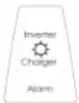 | On / Off / Charger-only switch = OnThe AC input voltage is switched through, and the charger operates in float mode. |
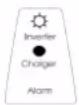 | On / Off / Charger-only switch = OnThe AC input is switched through and the charge current is zero. The inverter is switched on and, in case of PowerAssist, assists the AC input by supplying additional power to the load the General [4] chapter. |
 | On / Off / Charger-only switch = OnThe AC input voltage is switched through. The inverter is switched on and supplies power to the load or excess power to the mains. |
 | On / Off / Charger-only switch = Charger onlyThe AC input voltage is switched through, and the charger operates in bulk or absorption mode. |
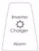 | On / Off / Charger-only switch = Charger onlyThe AC input is switched through, and the charger operates in float or storage mode. |
Note: The inverter/charger will shut down if four abnormal events occur within 30 seconds. It can be reset by switching to Off and then to On again.
For the latest and most up-to-date information about the blink codes, please refer to the Victron Toolkit app.
Scan the QR code or click on the below link to go to the Victron software downloads webpage.
https://www.victronenergy.com/support-and-downloads/software

3.3. Remote control
Remote control is possible with a 3-position switch or with a Digital Multi Control panel. The control panel has a simple rotary knob with which the maximum current of the AC input can be set: see PowerControl in the General [4] chapter. For the appropriate DIP switch settings, refer to the Configuration by DIP switches [16] chapter.
3.4. Maintenance
The Multi does not require specific maintenance. It will suffice to check all connections once a year. Avoid moisture and oil/soot/vapours and keep the device clean.
4. Installation

This product may only be installed by a qualified engineer.
Each system requires a method of disconnecting the AC and DC circuits. If the overcurrent protection device is a circuit breaker, it will also serve as the disconnect. If fuses are used, separate disconnect switches will be needed between the source and the fuses.
To reduce the risk of fire, do not connect to an ac load centre (circuit breaker panel) having multiwire branch circuits connected.
To reduce the risk of injury, charge only Lead Acid or LIFEPO4 type rechargeable batteries. Other types of batteries may burst causing personal injury and damage. Do not try to recharge non-rechargeable batteries.
Use of an attachment not recommended or sold by the marine unit manufacturer may result in a risk of fire, electric shock, or injury to persons.
DC CONNECTION PRECAUTIONS - Connect and disconnect DC output connections only after setting any marine unit switches to off position and removing AC cord from electric outlet or opening AC disconnect.
EXTERNAL CONNECTIONS TO CHARGER SHALL COMPLY WITH THE UNITED STATES COAST GUARD ELECTRICAL REGULATIONS (33CFR183, SUB PART I).
GROUNDING INSTRUCTIONS – This marine unit should be connected to a grounded, metal, permanent wiring system; or an equipment-grounding conductor should be run with circuit conductors and connected to equipment-grounding terminal or lead on unit. Connections to unit should comply with all local codes and ordinances
This product is not suitable for direct connection to a vehicle's electrical system. It should be connected to a dedicated DC system that includes a dedicated service or house battery, appropriate fusing, and the appropriate gauge of DC wiring. For recommendations on battery capacity, fuse rating, and cable gauge, refer to the Battery connection [9] chapter in this manual.

WARNING – RISK OF EXPLOSIVE GASES) WORKING IN VICINITY OF A LEAD-ACID BATTERY IS DANGEROUS. BATTERIES GENERATE EXPLOSIVE GASES DURING NORMAL BATTERY OPERATION. FOR THIS REASON, IT IS OF UTMOST IMPORTANCE THAT EACH TIME BEFORE SERVICING THE UNIT IN THE VICINITY OF THEBATTERY, YOU READ THIS MANUAL AND FOLLOW THE INSTRUCTIONS EXACTLY.
PERSONAL PRECAUTIONS:
- Someone should be within range of your voice or close enough to come to your aid when you work near a lead-acid battery
- Have plenty of fresh water and soap nearby in case battery acid contacts skin, clothing, or eyes.
- Wear complete eye protection and clothing protection. Avoid touching eyes while working near battery.
- If battery acid contacts skin or clothing, wash immediately with soap and water. If acid enters eye, immediately flood eye with running cold water for at least 10 min and get medical attention immediately.
- NEVER smoke or allow a spark or flame in vicinity of battery or engine.
- Be extra cautious to reduce risk of dropping a metal tool onto battery. It might spark or short-circuit battery or other electrical part that may cause explosion.
- Remove personal metal items such as rings, bracelets, necklaces, and watches when working with a lead-acid battery. A lead-acid battery can produce a short-circuit current high enough to weld a ring or the like to metal, causing a severe burn. • NEVER charge a frozen battery.
- If necessary to remove battery from vessel, always remove grounded terminal from battery first. Make sure all accessories in the vessels are off, so as not to cause an arc.
- Be sure area around battery is well ventilated. Clean battery terminals. Be careful to keep corrosion from coming in contact with eyes. Study all battery manufacturer's specific precautions such as removing or not removing cell caps while charging and recommended rates of charge.
- Clean battery terminals. Be careful to keep corrosion from coming in contact with eyes.
- Study all battery manufacturer's specific precautions such as removing or not removing cell caps while charging and recommended rates of charge.
4.1. location
The product must be installed in a dry, well-ventilated and heatproof area.

For safety purposes, this product should be installed in a heat-resistant environment. You should prevent the presence of e.g. chemicals, synthetic components, curtains or other textiles, etc., in the immediate vicinity.
There should be a clear space of at least 10cm around the appliance for cooling.

Excessively high ambient temperature will result in the following:
- Reduced service life.
- Reduced charging current.
- Reduced peak capacity, or shutdown of the inverter.
Try to keep the distance between the product and the battery to a minimum in order to minimise cable voltage losses.

Never position the appliance directly above the batteries.
For the location of the mounting holes, see the Dimension drawings [26] chapter.

MARINE UNIT LOCATION
- Locate marine unit away from battery in a separate, well ventilated compartment
- Never place marine unit directly above battery; gases from battery will corrode and damage marine unit.
- Never allow battery acid to drip on marine unit when reading gravity or filling battery.
- Do not operate marine unit in a closed-in area or restrict ventilation in any way.
4.2. Battery connection
For optimal performance, use batteries with a suitable capacity and cables with sufficient cross-section, as indicated in the below table:
| Inverter/charger Recommended battery capacity (Ah) | Recommended cable cross-section ( mm2 )For cables between 1.5 and 5m |
| 12/500/20 60 - 300 16 | |
| 12/1200/50 150 - 700 35 |
Battery connection procedure

Use an insulated box spanner in order to avoid shorting the battery terminals.
Avoid shorting the battery cables.
- Confirm battery cable polarity before connection. A reverse polarity connection will cause damage to the product (the safety fuse inside the Multi can be damaged).
- Connect battery cables to the Multi and the battery, see the Connection overview [22] chapter. Use a PZ 2 screwdriver for the 500VA unit and a flat screwdriver 6.5mm for the 1200VA unit.
Internal DC fuses
All servicing must be undertaken by qualified personnel.
| Inverter/charger Fuse type Fuse value (A) | |
| 12/500/20 MIDI or BF1 fuse 32V 125 - 60 | |
| 12/1200/50 MIDI or BF1 fuse 32V 200 - 100 |
4.3. AC connection

This product is a safety class I product (supplied with a ground terminal for safety purposes). Its AC input and/or output terminals and/or grounding point on the outside of the product must be provided with an uninterruptible grounding point for safety purposes.
The Multi is provided with a ground relay, see the Internal wiring diagram [23] chapter, that automatically connects the Neutral output to the chassis if no external AC supply is available. If an external AC supply is provided, the ground relay H will open before the input safety relay closes. This ensures the correct operation of an earth leakage circuit breaker that is connected to the output.
- In a fixed installation, uninterruptable grounding can be secured by means of the grounding wire of the AC input. Otherwise, the casing must be grounded.
- In a mobile installation, interrupting the shore connection will simultaneously disconnect the grounding connection. In that case, the casing must be connected to the chassis (of the vehicle) or to the hull or grounding plate (of the boat).
- In the case of a boat, direct connection to the shore ground is not recommended because of potential galvanic corrosion. The solution to this is using an isolation transformer.
The AC input and output terminal connectors can be found at the bottom of the Multi, see the Connection overview [22] chapter. The shore or mains cable must be connected to the connector with a three-wire cable. Use a three-wire cable with a flexible core and a cross-section of at least 1.5 mm 4
The inverter does incorporate a mains frequency isolating transformer. This precludes the possibility of DC current at any AC port. Therefore, type A RCDs can be used.
AC connection procedure
Proceed as follows to connect the AC cables:
- The AC output cable can be connected directly to the male connector (the connector pulls out).
- The terminal points are indicated clearly. From left to right: neutral (N), earth (PE), and phase (L1).
- The AC input cable can be connected directly to the female connector (the connector pulls out).
- The terminal points are indicated clearly. From left to right: neutral (N), earth (PE), and phase (L1).
- Push the "input" connector into the AC-in connector.
- Push the "output" connector into the AC-out connector.
4.4. Optional connections
A number of optional connections are possible:
4.4.1. Second battery
The Multi has a connection (+) for charging a starter battery. For connection see the Connection overview [22]chapter. The trickle charge output is protected by automatic overcurrent and overload protection (trip current=1A Imax=5.5 A).
4.4.2. Temperature sensor
The temperature sensor supplied with the product may be used for temperature-compensated charging. The sensor is insulated and must be mounted on the battery minus pole. Default output voltages for Float and Absorption are at 25\ °C . In adjust mode temperature compensation is disabled.
4.4.3. Remote control
The product can be remotely controlled in two ways:
- With an external 3-position switch
- With a Multi Control Panel
Please see the Configuration by DIP switches [16] chapter for appropriate DIP switch settings
4.4.4. Programmable relay
The Multi is equipped with a multi-functional relay that by default is programmed as an alarm relay. The relay can be programmed for all kinds of other applications, for example, to start a generator (VEConfigure software or VictronConenct app needed).
4.4.5. Parallel connection
The MultiPlus can be connected in parallel with several identical devices. To this end, a connection is established between the devices by means of standard RJ45 UTP cables. The system (one or more MultiPlus units plus an optional control panel) will require subsequent configuration, see the Configuration [13] chapter.
In the event of connecting MultiPlus units in parallel, the following requirements must be met:
- A maximum of six units can be connected in parallel.
- Only identical devices may be connected in parallel.
- The DC connection cables to the devices must be of equal length and cross-section.
- If a positive and a negative DC distribution point is used, the cross-section of the connection between the batteries and the DC distribution point must at least equal the sum of the required cross-sections of the connections between the distribution point and the MultiPlus units.
- Place the MultiPlus units close to each other, but allow at least 10cm for ventilation purposes under, above and beside the units.
- UTP cables must be connected with an RJ45-splitter from one unit to the other (and to the remote panel).
- A battery-temperature sensor need only be connected to one unit in the system. If the temperature of several batteries is to be measured, you can also connect the sensors of other MultiPlus units in the system (with a maximum of one sensor per MultiPlus). Temperature compensation during battery charging responds to the sensor indicating the highest temperature.
- Only one means of remote control (panel or switch) can be connected to the system.
Parallel connection diagram.
4.4.6. Three-phase connection
The MultiPlus can also be used in a 3-phase wye (Y) configuration. To this end, a connection between the devices is made by means of standard RJ45 UTP cables and RJ45-splittera splitter (the same as for parallel operation). The system (MultiPlus units plus an optional control panel) will require subsequent configuration, see the Configuration [13] chapter. For the prerequisites see the previous Parallel connection [11] chapter.
Note: The MultiPlus is not suitable for a 3-phase delta ( Δ ) configuration.
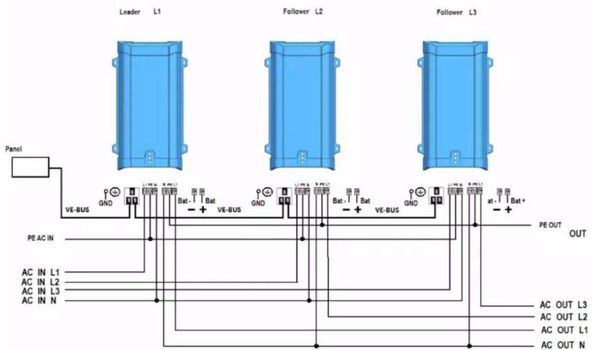
Three-phase connection diagram.
5. Configuration

Settings may only be changed by a qualified engineer.
Carefully read the instructions before changes are made.
Batteries should be placed in a dry and well-ventilated area during charging.
5.1. Standard settings: ready for use
On delivery, the Multi is set to standard factory values. In general, these settings are suitable for single-unit operation.

Warning: The standard charging voltage might not be appropriate for your batteries. Consult the manufacturer's documentation or your battery supplier for guidance.
| Setting Default value | |
| Inverter frequency 60 Hz | |
| Input frequency range 45 - 65 Hz | |
| Input voltage range 94 - 143 VAC | |
| Inverter voltage 120 VAC | |
| Stand-alone / parallel / 3-phase stand-alone | |
| Search mode off | |
| Ground relay on | |
| Charger on/off on | |
| Battery charge algorithm four-stage adaptive withBatterySafe mode | |
| Charge current 100 % of the maximum charge current | |
| Battery type Victron Gel Deep Discharge (also suitable for Victron AGM Deep Discharge) | |
| Automatic equalisation charging off | |
| Absorption voltage 14.4V | |
| Absorption time up to 8 hours (depending on bulk time) | |
| Float voltage | 13.8V |
| Storage voltage | 13.2V (not adjustable) |
| Repeated absorption time | 1 hour |
| Absorption repeat interval | 7 days |
| Bulk protection | off |
| AC input current limit | 12A (= adjustable current limit for PowerControl andPowerAssist functions) |
| UPS feature on | on |
| Dynamic current limiter off | off |
| Weak AC | off |
| Boost factor 2 | |
| Programmable relay | alarm function |
5.2. Explanations of settings
Settings that are not self-explanatory are described briefly below.
For further information on these settings, refer to the help files in the software configuration programs as indicated in the next Configuration by computer [15] chapter.
Inverter frequency
Output frequency if no AC is present at the input.
Adjustability: 50 Hz; 60 Hz
Input frequency range
Input frequency range accepted by the Multi. The Multi synchronises within this range with the AC input frequency. The output frequency is then equal to the input frequency.
Adjustability: 45 – 65 Hz.
Inverter voltage
Output voltage of the Multi in battery operation.
Adjustability: 95-128V.
Input voltage range
Voltage range accepted by the Multi. The Multi synchronises within this range with the AC input voltage. The output voltage is then equal to the input voltage.
Adjustability:
- Lower limit: 94 – 120V
• Upper limit: 120 – 143 V
Stand-alone / parallel operation / 2-3 phase setting
Using several devices, it is possible to:
- Increase total inverter power (several devices in parallel).
- Ccreate a split-phase system.
- Ccreate a 3-phase system.
The standard product settings are for standalone operation. For parallel, or three phase operation see the Parallel connection [11] and Three-phase connection [11] chapters.
Search mode
If search mode is "on", the power consumption in no-load operation is decreased by approx. 70 %. In this mode the Multi, when operating in inverter mode, is switched off in case of no load or very low load, and switches on every two seconds for a short period. If the output current exceeds a set level, the inverter will continue to operate. If not, the inverter will shut down again.
Search Mode can be set with a DIP switch.
Search Mode "shut down" and "remain on" load levels can be set with VEConfigure. The standard settings are:
- Shut down: 30 Watt (linear load)
- Turn on: 60 Watt (linear load)
AES (Automatic Economy Switch)
Instead of the search mode, the AES mode can also be chosen (with help of VEConfigure only).
If this setting is turned "on", the power consumption in no-load operation and with low loads is decreased by approx. 20 %, by slightly "narrowing" the sinusoidal voltage
Ground relay
With this relay the neutral conductor of the AC output is grounded to the chassis when the back-feed safety relay is open (See chapter Internal wiring diagram [23], item H). This ensures the correct operation of earth leakage circuit breakers in the output.
If a non-grounded output is required during inverter operation, this function must be turned off (use VE-Configure or teh VictronConnect app).
Charge curve
The standard setting is "Four-stage adaptive with BatterySafe mode". See chapter Battery charger [4] for a description. This is the recommended charge curve. See the help files in the software configuration programs for other features.
Battery type
The standard setting is the most suitable for Victron Gel Deep Discharge, Gel Exide A200, and tubular plate stationary batteries (OPzS). This setting can also be used for many other batteries: e.g. Victron AGM Deep Discharge and other AGM batteries, and many types of flat-plate flooded batteries. Four charging voltages can be set with DIP switches.
Automatic equalisation charging
This setting is intended for tubular plate traction batteries. During absorption, the voltage limit increases to 2.83 V/cell. Once the charge current has tapered down to less than 10 % of the set maximum current.
Absorption time
The absorption time depends on the bulk time (adaptive charge curve), so that the battery is optimally charged. If the "fixed" charging characteristic is selected, the absorption time is fixed. For most batteries, a maximum absorption time of eight hours is suitable. If an extra high absorption voltage is selected for rapid charging (only possible for open, flooded batteries!), four hours is preferable. With DIP switches, a time of eight or four hours can be set. For the adaptive charge curve, this determines the maximum absorption time.
Storage voltage, Repeated Absorption Time, Absorption Repeat Interval
See the Battery charger [4] chapter.
Bulk Protection
Default setting: off. When this setting is "on", the bulk charging time is limited to 10 hours. A longer charging time could indicate a system error (e.g. a battery cell short-circuit).
AC input current limit
These are the current limit settings at which PowerControl and PowerAssist come into operation. The factory setting is 12A.
UPS feature
If this setting is "on" and AC on the input fails, the Multi switches to inverter operation practically without interruption. The Multi can therefore be used as an Uninterruptible Power Supply (UPS) for sensitive equipment such as computers or communication systems. The output voltage of some small generator sets is too unstable and distorted for using this setting* – the Multi would continually switch to inverter operation. For this reason, the setting can be turned off. The Multi will then respond less quickly to AC input voltage deviations. The switchover time to inverter operation is consequently slightly longer, but most equipment (most computers, clocks or household equipment) is not adversely impacted.
Recommendation: Turn the UPS feature off if the Multi fails to synchronise, or continually switches back to inverter operation.
*In general, the UPS setting can be left "on" if the Multi is connected to a generator with a "synchronous AVR regulated alternator".
The UPS mode may have to be set to "off" if the Multi is connected to a generator with a "synchronous capacitor regulated alternator" or an asynchronous alternator.
Dynamic current limiter
Intended for generators, the AC voltage is generated by means of a static inverter (so-called "inverter" generator). In these generators, rpm is down-controlled if the load is low: this reduces noise, fuel consumption and pollution. A disadvantage is that the output voltage will drop severely or even completely fail in the event of a sudden load increase. More load can only be supplied after the engine is up to speed.
If this setting is "on", the Multi will reduce the charge current until the set current limit is reached. This allows the generator engine to get up to speed. This setting is also often used for "classic" generators that respond slowly to sudden load variation.
Weak AC
Strong distortion of the input voltage can result in the charger hardly operating or not operating at all. If Weak AC is set, the charger will also accept a strongly distorted voltage, at the cost of greater distortion of the input current.
Recommendation: Turn Weak AC on if the charger is hardly charging or not charging at all (which is quite rare!). Also, turn on the dynamic current limiter simultaneously and reduce the maximum charging current to prevent overloading the generator if necessary.
BoostFactor
Change this setting only after consulting with Victron Energy or with an engineer trained by Victron Energy!
Programmable relay
By default, the programmable relay is set as an alarm relay, i.e. the relay will de-energise in the event of an alarm or a pre-alarm (inverter almost too hot, ripple on the input almost too high, battery voltage almost too low). With VEConfigure software or the VictronConenct app, the relay can also be programmed for other purposes, for example, to provide a generator starting signal.
5.3. Configuration by computer
All settings can be changed by means of a phone, tablet or computer.
The following is required:
- The VictronConnect app or the VEConfigure3 software package. Both can be downloaded free of charge from the downloads section on www.victronenergy.com.
- An Interface MK3-USB and a RJ45 UTP cable.
- Refer to the VictronConnect configuration guide for VE.Bus products document for further instructions and further explanation of the various settings.
Note that some settings can also be changed with DIP switches (see the next Configuration by DIP switches [16] chapter).
5.4. Configuration by DIP switches
Some settings can be changed with DIP switches.
Procedure:
- Turn the Multi on, preferably without load and without AC voltage on the input. The Multi will then operate in inverter mode.
- Set the DIP switches as required.
- Store the settings by moving DIP switch 6 to "on" and back to "off".
DIP switch 1
Default setting: to operate the product with the "On/Off/Charger Only" switch ds 1: "off" When combined with the Digital Multi Control panel, a VE.Bus Smart dongle, CCGX, Venus GX or alike, DIP switch 1 should also be in the "off" position. Setting for operation with a 3-position remote switch: ds 1: "on" The 3-position switch must be wired to terminal H, see appendix A.
Use only one type of remote control: either a switch or a Digital Multi Control panel.
DIP switch 2 and 3
These DIP switches can be used to set:
- Battery charge voltage and Absorption time
- Inverter frequency
- Search mode
(For more system settings, use VEConfigure or the VictronConnect app)
| DS 2 - DS 3 | Absorption voltage (V) | Float voltage (V) | Storage Voltage (V) | Absorption Time (hours) | Suitable battery types |
| DS 2=offDS 3=off(default) | 14.4 13.8 13.2 8 | Gel Victron deep dischargeGel Exide A200AGM Victron deep discharge | |||
| DS 2=onDS 3=off | 14.1 13.8 13.2 8 | Gel Victron long life (OPzV)Long Life (OPzV)Gel Exide A600 (OPzV)Gel MK batteryLi-ion (LiFePO4) | |||
| DS 2=offDS =on | 14.7 13.8 13.2 5 | AGM Victron deep dischargeTubular plate or OPzS batteries in semi-float modeAGM spiral cell |
Dip switch 4
Inverter frequency off = 50 Hz on = 60 Hz
Dip switch 5
Search Mode off = off on = on
Store the settings by moving DIP switch 6 to "on" and back to "off".
Example 1 (factory setting) Example 2 Example 3
| DS-1: 3-position switchDS-2: charge voltageDS-3: charge voltageDS-4: FrequencyDS-5: Search modeDS-6: Store setting |  | DS-1DS-2DS-3DS-4DS-5DS-6 | 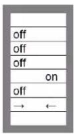 | DS-1DS-2DS-3DS-4DS-5DS-6 |  |
| 1: 3-position switch connected2,3: GEL 14.4V4: Frequency 60Hz5: Search mode off6: Store setting: off→ on→ off | 1: 3-position switch connected2,3: GEL long life 14.4V (lithium)4: Frequency 50Hz5: Search mode off6: Store setting: off→ on→ off | 1: 3-position switch connected2,3: Tubular plate 15V4: Frequency 60Hz5: Search mode on6: Store setting: off→ on→ off | |||
Example 1 is the factory setting (since factory settings are entered by computer, all DIP switches of a new product are set to "off").
Store the settings by changing switch DS-6 from off to on, and then back to off. The LEDs "charger" and "alarm" will flash to indicate acceptance of the settings.
6. Troubleshooting
Proceed as follows for quick detection of common faults. DC loads must be disconnected from the batteries and the AC loads must be disconnected from the inverter before the inverter and/or battery charger is tested.
Consult your Victron Energy dealer if the fault cannot be resolved.
| Problem Cause Solution | ||
| The inverter fails to operate when switched on | The battery voltage is too high or too low | Ensure that the battery voltage is within the correct value. |
| The inverter fails to operate Processor in no function-mode Disconnect mains voltage. Switch front switch off, wait 4 seconds. Switch front switch on. | ||
| The alarm LED flashes Pre-alarm alternative 1: The DC input voltage is low | Charge the battery or check the battery connections. | |
| The alarm LED flashes Pre-alarm alternative 2: The ambient temperature is too high | Place the inverter in a cool and well-ventilated room or reduce the load. | |
| The alarm LED flashes Pre-alarm alternative 3: The load on the inverter is higher than the nominal load | Reduce the load. | |
| The alarm LED flashes Pre-alarm alternative 4: Voltage ripple on the DC input exceeds 1.25Vrms | Check the battery cables and terminals. Check the battery capacity; increase if necessary. | |
| The alarm LED flashes intermittently | Pre-alarm alternative 5: Low battery voltage and excessive load | Charge the batteries, reduce the load or install batteries with a higher capacity. Use shorter and/or thicker battery cables. |
| The alarm LED is on The inverter did cut out following a pre-alarm | Check the table for the appropriate course of action. | |
| The charger is not functioning The AC input voltage or frequency is out of range | Ensure that the input voltage is between 185 VAC and 265 VAC, and that the frequency matches the setting. | |
| The battery is not being charged fully | Incorrect charging current Set the charging current at between 0.1 and 0.2x battery capacity. | |
| A defective battery connection Check the battery terminals. | ||
| The absorption voltage has been set to an incorrect value | Adjust the absorption voltage to the correct value. | |
| The float voltage has been set to an incorrect value | Adjust the float voltage to the correct value. | |
| The internal DC fuse is defective Inverter is damaged | ||
| The battery is overcharged The absorption voltage has been set to an incorrect value | Adjust the absorption voltage to the correct value | |
| Adjust the float voltage to the correct value. | ||
| A defective battery Replace the battery. | ||
| The battery is too small Reduce the charging current or use a battery with a higher capacity. | ||
| The battery is too hot Connect a temperature sensor. | ||
| Battery charge current drops to 0 when the absorption voltage is reached | Alternative 1: Battery overtemperature (>50 °C) | Allow battery to cool down - Place battery in a cool environment - Check for shorted cells |
| Problem Cause Solution | |
| Alternative 2:Battery temperature sensor faulty |
7. Technical data
7.1. Technical specifications
| MultiPlus 12/500/20 - 120Vac Multiplus 12/1200/50 - 120Vac | ||
| PowerControl / PowerAssist Yes / No Yes / Yes | ||
| Transfer switch 16A | ||
| INVERTER | ||
| Input voltage range 9.5 - 17Vdc | ||
| Output voltage 120Vac ± 2% | ||
| Output\ frequency(1) | 60Hz ± 0,1% | |
| Cont. output power at 25°C (77°F) (3) | 500VA 1200VA | |
| Cont. output power at 25°C (77°F) 430W 1000W | ||
| Cont. output power at 40°C (104°F) 400W 900W | ||
| Cont. output power at 65°C (149°F) 300W 600W | ||
| Peak power 900W 2400W | ||
| Maximum efficiency 90% | 93% | |
| Zero-load power | 6W | 10W |
| Zero-load power search mode | 2W | 3W |
| CHARGER | ||
| AC Input voltage range | 95 - 140Vac | |
| AC input frequency range | 45 - 65Hz | |
| Charge voltage 'absorption' | 14.4V | |
| Charge voltage 'float' | 13.8V | |
| Storage mode 13.2V | ||
| Charge current house battery (4) | 20A | 50A |
| Charge current starter battery | 1A | |
| Battery temperature sensor | Yes | |
| GENERAL | ||
| Programmable relay (5) | Yes | |
| Protection (2) | a - g | |
| Operating temperature | -40 to +65°C (-40 to + 140°F), fan assisted cooling | |
| Humidity | Maximum 95%, non-condensing | |
| ENCLOSURE | ||
| Material & colour | Steel/ABS, blue RAL 5012 | |
| Protection category | IP 21 | |
| Battery-connection | 16 mm2 | 35 mm2 |
| 230V AC-connection | G-ST18i connector | |
| Weight | 4.4kg | 8.2kg |
| Dimensions (h x w x d) | 311 x 182 x 100 mm | 406 x 250 x 100 mm |
| STANDARDS | ||
| Safety | EN-IEC 60335-1, EN-IEC 60335-2-29, EN 62109-1 | |
| Emission / Immunity | EN 55014-1, EN 55014-2, EN-IEC 61000-3-2, EN-IEC 61000-3-3IEC 61000-6-1, IEC 61000-6-2, IEC 61000-6-3 | |
| Road vehicles ECE R10-4 | ||
| 1) Can be adjusted to 50Hz2) Protectiona. Output short circuitb. Overloadc. Battery voltage too highd. Battery voltage too lowe. Temperature too highf. 120Vac on inverter outputg. Input voltage ripple too high | 3) Non-linear load, crest factor 3:14) Up to 25°C (77°F) ambient5) Programmable relay which can be set for:general alarm, DC under voltage or generator start/stop signal functionAC rating: 230V/4ADC rating: 4A up to 35Vdc, 1A up to 60Vdc | |
7.2. Connection overview
![graph TD A["Female GST 18 connector"] --> B["PE"] C["Male GST 18 connector"] --> D["PE"] B --> E["AC INPUT"] D --> F["AC OUTPUT"] E --> G["Settings"] F --> H["Chromeda ON OFF CHROM (CHARGER ONLY)"] G --> I["VE.BUS"] H --> J["Remote Temp"] I --> K["ON Ch + - +"] J --> L["ON Ch + - +"] K --> M["+"] L…](/content/2026/05/849939/images/c16953a51744f67bed9fc3cb501d72bc1f41cc2f63bd95b98bd46fa5953ce4ba.jpg)
ID Description
A DIP switches (remove plastic cover)
B On/off/charger only switch
C VE.Bus communication port
D Temperature sensor terminal
E Programmable relay terminal
F Battery negative connection
G Starter battery positive connection
H Remote control terminal
I AC input terminal (N, PE, L1)
J AC output terminal (N, PE, L1)
K Battery positive
L Earth connection
7.3. Internal wiring diagram
![graph TD A["Phoenix Multi Compact chassis"] --> B["D input"] A --> C["L"] A --> D["N"] A --> E["PE"] A --> F["F"] A --> G["G"] A --> H["H"] A --> I["J"] A --> J["K"] A --> K["To battery"] style A fill:#f9f,stroke:#333 style B fill:#ccf,stroke:#333 style C fill:#ccf,stroke:#333 style D fill:#ccf,stro…](/content/2026/05/849939/images/78ce62cf767e2530c3875f5a4df392ee28cdb1a5914b5e42c4c80e70a31a2154.jpg)
| ID Description |
| D AC input (L, N, PE). |
| E AC output (L, N, PE). |
| F Ground AC input and AC output are connected to chassis. |
| G Back feed safety relay. |
| H Ground relay (closed when the back feed relay is open). |
| I DC fuse. |
| J Bidirectional converter. |
| K Chassis on input/output ground terminals should be permanently connected to ground. |
7.4. Four-stage charge algorithm
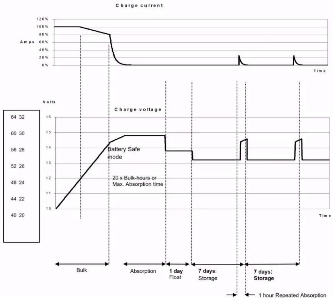
| charge stage Description | |
| Bulk Entered when charger is started. Constant current is applied until the gassing voltage is reached (14,4 V resp. 28.8V, temperature compensated). | |
| Battery safe | If, in order to quickly charge a battery, a high charge current in combination with a high absorption voltage has been chosen, the Multi will prevent damage due to excessive gassing by automatically limiting the rate of voltage increase once the gassing voltage has been reached. The Battery Safe period is part of the calculated absorption time. |
| Absorption A constant voltage period to fully charge the battery. The absorption time is equal to 20x bulk time or the set maximum absorption time, whichever comes first. | |
| Float Float voltage is applied to keep the battery fully charged and to protect it against self-discharge. | |
| Storage After one day of Float charge the charger switches to storage. This is 13,2 V resp. 26,4 V (for 12 V and 24 V charger). This will limit water loss to a minimum. After an adjustable time (default = 7 days) the charger will enter Repeated Absorption for an adjustable time (default = 1 hour). | |
7.5. Temperature compensation charge chart

- Default output voltages for Float and Absorption are at 25 °C.
- Reduced Float voltage follows Float voltage and Raised Absorption voltage follows Absorption voltage.
- In adjust mode temperature compensation does not apply.
7.6. Dimension drawings
Multiplus 12/500/20 - 120V


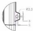
| Dimension Drawing - MultiPlus | |
| PMP121500100 | MultiPlus 12/500/20-16 120V VE.Bus |
| PMP121500000 | MultiPlus 12/500/20-16 230V VE.Bus |
| PMP241500000 | MultiPlus 24/500/10-16 230V VE.Bus |
| PMP481500000 | MultiPlus 48/500/6-16 230V VE.Bus |
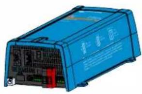
Dimensions in mm

victron energy
BLUE POWER
Multiplus 12/1200/50 - 120V


DETAIL A
SCALE 2:3

DETAIL B
SCALE 2:3

Dimensions in mm

victron energy
BLUE POWER


- TABLE OF CONTENTS
- SAFETY INSTRUCTIONS .... 2
- DESCRIPTION 4
- OPERATION 6
- INSTALLATION 8
- CONFIGURATION 13
- TROUBLESHOOTING 18
- TECHNICAL DATA 20
- SAFETY INSTRUCTIONS
- GENERAL
- INSTALLATION
- TRANSPORT AND STORAGE
- SYMBOLS ON ENCLOSURE
- DESCRIPTION
- MULTIFUNCTIONAL
- UNINTERRUPTED AC POWER
- PARALLEL AND 3-PHASE OPERATION CAPABILITY
- POWERCONTROL – DEALING WITH A LIMITED GENERATOR OR SHORESIDE POWER
- PROGRAMMABLE RELAY
- BATTERY CHARGER
- ADAPTIVE 4-STAGE CHARGING CHARACTERISTICS: BULK – ABSORPTION – FLOAT – STORAGE
- THE RIGHT AMOUNT OF CHARGE: VARIABLE ABSORPTION TIME
- PREVENTING DAMAGE DUE TO EXCESSIVE GASSING: THE BATTERYSAFE MODE
- LESS MAINTENANCE AND AGEING WHEN THE BATTERY IS NOT IN USE: THE STORAGE MODE
- TWO DC OUTPUTS FOR CHARGING TWO BATTERIES
- INCREASING SERVICE LIFE OF THE BATTERY: TEMPERATURE COMPENSATION
- MORE ON BATTERIES AND CHARGING
- SELF CONSUMPTION – SOLAR ENERGY STORAGE SYSTEMS
- OPERATION
- ON/OFF/CHARGER-ONLY SWITCH
- LED INDICATIONS
- REMOTE CONTROL
- MAINTENANCE
- LOCATION
- MARINE UNIT LOCATION
- BATTERY CONNECTION
- BATTERY CONNECTION PROCEDURE
- INTERNAL DC FUSES
- AC CONNECTION
- AC CONNECTION PROCEDURE
- OPTIONAL CONNECTIONS
- SECOND BATTERY
- TEMPERATURE SENSOR
- PARALLEL CONNECTION
- THREE-PHASE CONNECTION
- CONFIGURATION
- STANDARD SETTINGS: READY FOR USE
- EXPLANATIONS OF SETTINGS
- INPUT FREQUENCY RANGE
- INVERTER VOLTAGE
- INPUT VOLTAGE RANGE
- STAND-ALONE / PARALLEL OPERATION / 2-3 PHASE SETTING
- SEARCH MODE
- AES (AUTOMATIC ECONOMY SWITCH)
- GROUND RELAY
- CHARGE CURVE
- BATTERY TYPE
- AUTOMATIC EQUALISATION CHARGING
- ABSORPTION TIME
- STORAGE VOLTAGE, REPEATED ABSORPTION TIME, ABSORPTION REPEAT INTERVAL
- BULK PROTECTION
- AC INPUT CURRENT LIMIT
- UPS FEATURE
- DYNAMIC CURRENT LIMITER
- WEAK AC
- BOOSTFACTOR
- CONFIGURATION BY COMPUTER
- CONFIGURATION BY DIP SWITCHES
- PROCEDURE
- DIP SWITCH 1
- DIP SWITCH 2 AND 3
- DIP SWITCH 4
- DIP SWITCH 5
- TROUBLESHOOTING
- TECHNICAL DATA
- CONNECTION OVERVIEW
- ID DESCRIPTION
- INTERNAL WIRING DIAGRAM
- FOUR-STAGE CHARGE ALGORITHM
- DIMENSION DRAWINGS
Brand : VICTRON ENERGY
Model : MultiPlus 500 ВA
Category : Battery charger