
KVM0108A - Computer Adapter APC - Free user manual and instructions
Find the device manual for free KVM0108A APC in PDF.


| Product Type | KVM Switch (Computer Adapter) |
| Model | APC KVM0108A |
| Number of Ports | 8 |
| Connector Type | RJ-45 (Cat 5e/6) for KVM ports; 2 x 6-pin Mini-DIN and 2 x USB for keyboard and mouse; 2 x HDB-15 for video |
| Video Resolution | Up to 1600 x 1200 @ 60 Hz (40 m); 1280 x 1024 @ 75 Hz (50 m) |
| Power Input | 100-240 VAC, 50/60 Hz, 1.0A |
| Power Consumption | 20.6 W max |
| Operating Temperature | 0 - 50°C (32°F - 122°F) |
| Storage Temperature | -20°C - 60°C (-4°F - 140°F) |
| Humidity | 0 - 80% RH, non-condensing |
| Dimensions (W x D x H) | 42.4 cm x 18.8 cm x 4.3 cm (16.69” x 7.4” x 1.69”) – 1U rack mount |
| Net Weight | 2.4 kg (5.28 lbs) |
| Shipping Weight | 3.9 kg (8.58 lbs) |
| Mounting | 19-inch rack (1U), front or rear mounting |
| Operating Systems Supported | Microsoft Windows, Linux, UNIX, Mac, DOS |
| Control Methods | On Screen Display (OSD), hotkeys, front panel buttons |
| Security | Password protection with up to 10 user accounts and 1 administrator account |
| Scalability | Up to 31 switches in chain, controlling up to 256 servers |
| Special Features | Auto-scan, broadcast mode, hot-pluggable, firmware upgrade via utility, hotkey command mode |
| Warranty | 2 years from date of purchase (factory warranty) |
Frequently Asked Questions - KVM0108A APC
User questions about KVM0108A APC
0 question about this device. Answer the ones you know or ask your own.
Ask a new question about this device
Download the instructions for your Computer Adapter in PDF format for free! Find your manual KVM0108A - APC and take your electronic device back in hand. On this page are published all the documents necessary for the use of your device. KVM0108A by APC.
USER MANUAL KVM0108A APC
natural_image
Line drawing of a network switch device (no text or symbols visible)Schneider Electric Legal Disclaimer
The information presented in this manual is not warranted by Schneider Electric to be authoritative, error free, or complete. This publication is not meant to be a substitute for a detailed operational and site specific development plan. Therefore, Schneider Electric assumes no liability for damages, violations of codes, improper installation, system failures, or any other problems that could arise based on the use of this Publication.
The information contained in this Publication is provided as is and has been prepared solely for the purpose of evaluating data center design and construction. This Publication has been compiled in good faith by Schneider Electric. However, no representation is made or warranty given, either express or implied, as to the completeness or accuracy of the information this Publication contains.
IN NO EVENT SHALL SCHNEIDER ELECTRIC, OR ANY PARENT, AFFILIATE OR SUBSIDIARY COMPANY OF Schneider Electric OR THEIR RESPECTIVE OFFICERS, DIRECTORS, OR EMPLOYEES BE LIABLE FOR ANY DIRECT, INDIRECT, CONSEQUENTIAL, PUNITIVE, SPECIAL, OR INCIDENTAL DAMAGES (INCLUDING, WITHOUT LIMITATION, DAMAGES FOR LOSS OF BUSINESS, CONTRACT, REVENUE, DATA, INFORMATION, OR BUSINESS INTERRUPTION) RESULTING FROM, ARISING OUT, OR IN CONNECTION WITH THE USE OF, OR INABILITY TO USE THIS PUBLICATION OR THE CONTENT, EVEN IF SCHNEIDER ELECTRIC HAS BEEN EXPRESSLY ADVISED OF THE POSSIBILITY OF SUCH DAMAGES. SCHNEIDER ELECTRIC RESERVES THE RIGHT TO MAKE CHANGES OR UPDATES WITH RESPECT TO OR IN THE CONTENT OF THE PUBLICATION OR THE FORMAT THEREOF AT ANY TIME WITHOUT NOTICE.
Copyright, intellectual, and all other proprietary rights in the content (including but not limited to software, audio, video, text, and photographs) rests with Schneider Electric or its licensors. All rights in the content not expressly granted herein are reserved. No rights of any kind are licensed or assigned or shall otherwise pass to persons accessing this information.
This Publication shall not be for resale in whole or in part.
Contents
General Information ....1
Overview 1
Features 1
Safety 2
Safety map 2
KVM Safety 3
Taking Delivery 4
Accessory Inventory 4
Requirements 5
Console 5
Computers 5
KVM Server Modules and cables 5
Supported operating systems ....6
Maximum server connections 6
Component Identification 7
Front 7
Rear 8
Installation 9
Overview 9
Rack Mounting 9
Rack mounting 9
Rack Mounting - Rear 10
Optional KVM to LCD Console Mounting 11
Single Level KVM Switch Installation 11
Single level installation diagram 11
Tiering multiple KVM switches 12
To set up a Chained tiering installation: 12
Chained Tiering Installation Diagram 12
Hardware Setup 13
Cable Length Considerations 13
Hot Plugging 13
Powering Off and Restarting 13
Port ID Numbering 14
On Screen Display (OSD) Operation 15
Overview 15
OSD Navigation 16
OSD Main Screen Headings 17
OSD Functions 17
F1: GOTO 17
F2: LIST 18
F3: SET 19
F4: ADM 21
F5: SKP 23
F6: BRC 23
F7: SCAN 24
F8: LOGOUT 24
Hotkey Operation ....25
Hotkey Port Control 25
Invoking Hotkey Mode 25
[Num Lock] + [-] 25
[CTRL] + [F12] 25
Hotkey mode environment 25
Exiting hotkey mode 25
Selecting the Active Port 26
Auto Scan Mode Switching 26
Setting the scan interval 26
Invoking Auto Scan 26
Exiting Auto Scan 26
Skip Mode Switching 27
Entering skip mode 27
Exiting skip mode 27
Computer Keyboard/Mouse Reset 27
Setting the Hotkey Beeper ON/OFF 27
Setting the Hotkey Key Combination 27
Setting the OSD Hotkey combination 28
Setting the Port Operating System 28
Restore the Default Values 28
Hotkey Summary Table 29
Keyboard Emulation ....30
Mac Keyboard 30
Sun Keyboard 31
Firmware Upgrade Utility 32
Introduction 32
Performing the Upgrade 33
Starting the upgrade 33
Upgrade succeeded 33
Upgrade failed 34
Firmware Upgrade Recovery 34
Main board firmware upgrade recovery 34
Server Module firmware upgrade recovery 34
Troubleshooting 35
Overview 35
OSD Factory Default Settings 35
Connection Tables 36
KVM0108A 36
KVM0116A 36
Specifications ....37
Radio Frequency Interference 38
USA—FCC 38
Canada—ICES 38
Japan—VCCI 38
Taiwan—BSMI 38
European Union 38
United Kingdom 38
Warranty 39
Two-Year Factory Warranty 39
Terms of warranty 39
Non-transferable warranty 39
Exclusions 39
Warranty claims 40
Worldwide Customer Support 41
General Information
Overview
KVM0108A and KVM0116A KVM Switches
The KVM switches allow administrators to access and control multiple servers from a single PS/2 or USB KMM (keyboard, monitor, and mouse) console. There is no software to configure.
| SKU | Local Connection Remote Connection KVM Ports | ||
| KVM0108A 1 | 0 8 | ||
| KVM0116A 1 | 0 16 | ||
- An auto-sensing function recognizes the position of each station on the installation, eliminating the need to manually set the position, and a front panel LED displays each station's position.
- Updates are available at www.apc.com. The Firmware Upgrade function performs installation.
Features
- Simple installation and operation: Plug-and-play installation. No software required. Station positions are automatically recognized. Computer selection is done using hotkeys or multi-language On Screen Display (OSD) menus.
- Single console control: Access and control up to 8 (KVM0108A) or 16 (KVM0116A) servers from a single PS/2 or USB KVM (keyboard, monitor, and mouse) console.
- Scalability: Connect up to 31 switches. Control up to 512 servers (KVM0116A) from the KVM console.
- Easy installation: Plug cables into their appropriate ports. No software to configure.
- Hardware independent cross-platform support.
- RJ-45 connectors and cat 5e/6 cabling: The KVM0108A or KVM0116A can be installed in a 1U system rack. Take advantage of internal network wiring in most modern commercial buildings.
- KVM adapter cables connect to servers. Mix PS/2 and USB interfaces connecting the KVM switch to the devices.
• Strong password protection prevents unauthorized access. - Multiple user accounts: Supports up to 10 user and 1 administrator accounts.
- Effortless upgrades: Simultaneously upgrade all in series KVM switches and server modules.
- Auto scanning and broadcast mode: Auto scanning provides hands-free monitoring of selected devices at variable rates. Broadcast Mode sends commands from the console to all computers. Performs software installation, upgrades, and shutdowns simultaneously.
- Superior video quality: Supports the video resolutions up to 1600x1200@60hz for up to 40 meters, and 1280x1024@75hz for up to 50 meters with the KVM Cable Adapter.
- Hot pluggable: Add or remove components without powering off the KVM switch.
- Server modules (Adapter cables) with ID: The KVM switch automatically recognizes the new KVM Cable Adapter. Device ID and attributes are stored in the adapter cables allowing you to hot-swap port connections without having to reconfigure attributes.
Safety
Safety map
Read the instructions carefully to become familiar with the equipment before trying to install, operate, service, or maintain it. The following special messages may appear throughout this manual or on the equipment to warn of potential hazards or to call attention to information that clarifies or simplifies a procedure.

The addition of this symbol to a Danger or Warning safety label indicates that an electrical hazard exists which will result in personal injury if the instructions are not followed.

This is the safety alert symbol. It is used to alert you to potential personal injury hazards. Obey all safety messages that follow this symbol to avoid possible injury or death.
DANGER
DANGER indicates an imminently hazardous situation which, if not avoided, will result in death or serious injury.
WARNING
WARNING indicates a potentially hazardous situation which, if not avoided, can result in death or serious injury.
CAUTION
CAUTION indicates a potentially hazardous situation which, if not avoided, can result in minor or moderate injury.
NOTICE
NOTICE addresses practices not related to physical injury including certain environmental hazards, potential damage or loss of data.
KVM Safety
Read all of these instructions. Save them for future reference. Follow all warnings and instructions marked on the device.
DANGER
HAZARD OF ELECTRIC SHOCK
- Do not use the device near water, Never spill liquid of any kind on the device.
- Unplug the device from the wall outlet before cleaning. Do not use liquid or aerosol cleaners. Use a damp cloth for cleaning.
- The device should be operated from the type of power source indicated on the marking label. If you are not sure of the type of power available, consult your dealer or local power company.
- To prevent damage to your installation it is important that all devices are properly grounded. The device is equipped with a 3-wire grounding type plug. This is a safety feature. If you are unable to insert the plug into the outlet, contact your electrician to replace the outlet. Do not attempt to defeat the purpose of the grounding-type plug. Always follow local/national wiring codes.
- If an extension cord is used with this device make sure that the total of the ampere ratings of all products used on this cord does not exceed the extension cord ampere rating. Make sure that the total of all products plugged into the wall outlet does not exceed 15 amperes.
- To help protect your system from sudden, transient increases and decreases in electrical power, use a surge suppressor, line conditioner, or uninterruptible power supply (UPS).
- Position system cables and power cables carefully; Be sure that nothing rests on any cables.
- Never push objects of any kind into or through cabinet slots. They may touch dangerous voltage points or short out parts resulting in a risk of fire or electrical shock.
- Use the power cord(s) supplied with this package. If it becomes necessary to replace the cords supplied with this package, be sure to use cords of at least the same standard as the ones provided. Contact your dealer for information about power cords
- Do not attempt to service the device yourself. Refer all servicing to qualified service personnel.
Failure to follow these instructions can result in death or serious injury.
▲CAUTION
INJURY OR EQUIPMENT DAMAGE
- Do not connect the RJ-11 connector marked "UPGRADE" to a public telecommunication network.
- Before working on the rack, make sure that the stabilizers are secured to the rack, extended to the floor, and that the full weight of the rack rests on the floor. Install front and side stabilizers on a single rack or front stabilizers for joined multiple racks before working on the rack.
- Always load the rack from the bottom up, and load the heaviest item in the rack first.
- Make sure that the rack is level and stable before extending a device from the rack.
- Use caution when pressing the device rail release latches and sliding a device into or out of a rack; the slide rails can pinch your fingers.
- After a device is inserted into the rack, carefully extend the rail into a locking position, and then slide the device into the rack.
- Do not overload the AC supply branch circuit that provides power to the rack. The total rack load should not exceed 80 percent of the branch circuit rating.
- Make sure that all equipment used on the rack, including power strips and other electrical connectors, is properly grounded.
- Ensure that proper airflow is provided to devices in the rack.
- Ensure that the operating ambient temperature of the rack environment does not exceed the maximum ambient temperature specified for the equipment by the manufacturer
- Do not step on or stand on any device when servicing other devices in a rack.
- Do not place the device on an unstable surface. If the device falls, serious damage will result.
- Do not block ventilation openings. Overheating of internal components may occur.
- Route the power cord and cables so that they cannot be stepped on or tripped over.
Failure to follow these instructions can result in injury or equipment damage.
Taking Delivery
Examine the components at the time of delivery to be sure all parts are present and in good working order. Anything missing or damaged must be reported immediately to the shipping firm and to APC.
Accessory Inventory
• 1 KVM0108A or KVM0116A KVM switch
• 1 firmware upgrade cable
• 1 NEMA 5-15 power cord
1 C13 - C14 power cord
- 1 rack mount bracket
• Literature Kit: Quick Start Guide, Safety Sheet, and China ROHS.
Requirements
Console
- VGA, SVGA, or multi-sync monitor capable of the highest resolution that you will be using on any server in the installation
• PS/2 or USB mouse/keyboard
Computers
The following equipment must be installed on the servers that connect to the KVM switch ports:
• VGA, SVGA, or multi-sync port
- Type A USB port and USB host controller
• or 6-pin Mini-DIN keyboard and mouse ports
KVM Server Modules and cables
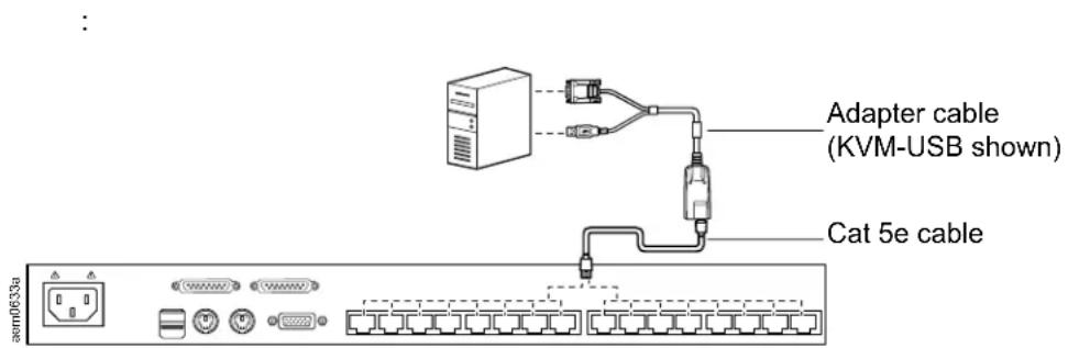
NOTE: KVM server modules are also referred to as adapter cables.
- The Cat 5e/6 cable is required to connect the KVM switch to one of the KVM adapter cables.
- The following KVM adapter cables are required for use with the KVM switch:
| Module Function | |
| KVM-PS2 Connects to devices with PS/2 ports | |
| KVM-USB Connects to devices with USB ports | |
| AP5262 APC KVM Chain In/Out Cable - 2 ft (0.6 m) | |
| AP5263 APC KVM Chain In/Out Cable - 6 ft (1.8 m) |
Supported operating systems
- Microsoft Windows
- Linux
- UNIX
• Mac
• DOS
Maximum server connections
| Parent KVM Model | Ports | Child Tiered KVM Ports | Max Connections (Tiered) | Chained Connections |
| KVM0108A | 8 KVM0108A | 8 265 32 | ||
| KVM0116A | 16 KVM0216A | 16 512 32 |
Component Identification
Front
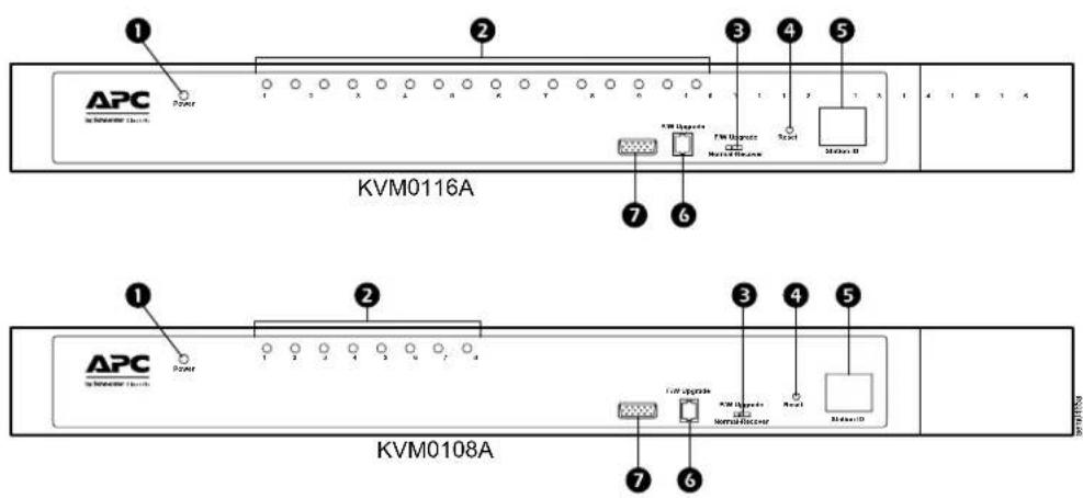
| No. | Component Description | |
| 1 | Power LED Lights to indicate that the KVM switch is powered and ready to operate. | |
| 2 | Port LEDs | The Port LEDs provide status information about their corresponding KVM Ports• GREEN: The server attached to the port is On Line.• RED: The server attached to the port is Selected (has KVM focus).• GREEN + RED (ORANGE): The server attached to the port is On Line and Selected.The LEDs are continuously ON under normal conditions. An LED will flash at half second intervals when its corresponding port is accessed under Auto Scan Mode or Skip Mode |
| 3 | Firmware Upgrade Recovery Switch | During normal operation and while performing a firmware upgrade, this switch should be in the “normal” position. If a firmware upgrade operation does not complete successfully, this switch is used to perform a firmware upgrade recovery (see “Firmware Upgrade Utility” on page 32). |
| 4 | Reset Switch | The switch is recessed and must be pushed with a small object, such as the end of a paper clip or a ballpoint pen. To perform a system reset, press and release when the unit is running.Note: This does not clear User Account information. |
| 5 | Station ID LED | The KVM switch's Station ID is displayed here. If this is a single station installation or the first station on the installation, the KVM switch ID is “01.”On a tiered installation, the KVM switch auto-senses its position and displays the station ID that corresponds to its place in the installation (see “Port ID Numbering” on page 14). |
| 6 | Firmware Upgrade Port | The Firmware Upgrade Cable that transfers the firmware upgrade data from the administrator's computer to the KVM switch, plugs into this RJ-11 connector. |
| 7 | Console Port The port is for installation with Rack LCD Console AP5717 or AP5719. | |
Rear
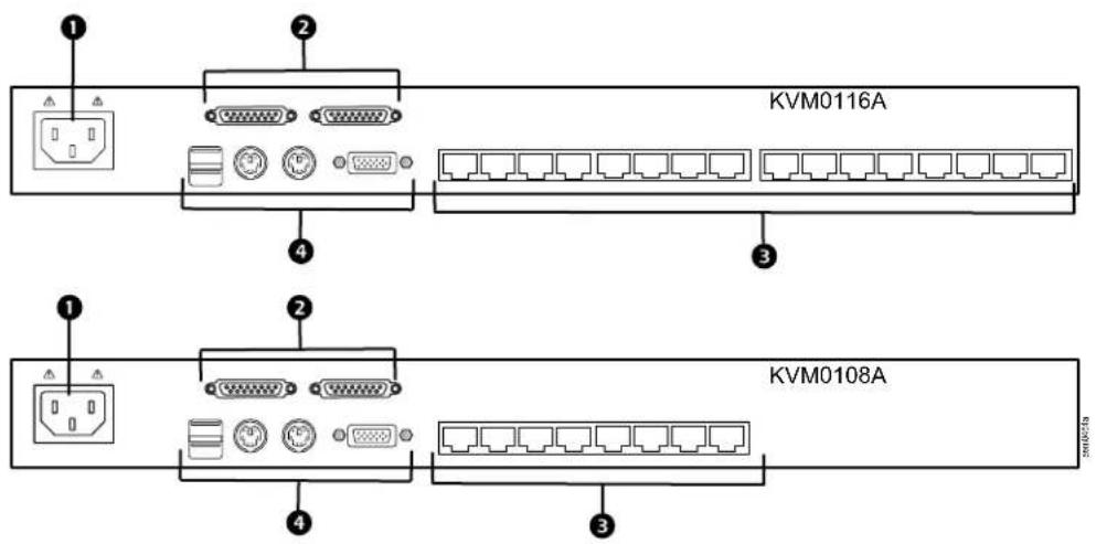
| Item | Component Description | |
| 1 | Power Socket The power cord to the AC source plugs in here. | |
| 2 | Chain In/Out Ports | When cascading KVM switches, the cables plug in here (see “Tiering multiple KVM switches” on page 12).The port on the left is the Chain In port; the port on the right is the Chain Out port. |
| 3 | KVM Port Section | The Cat 5e/6 cables that link to the KVM adapter cables (which link to the computers) plug in here. |
| 4 | Console Ports | If this is a single station installation, or if this is the first station of a tiered installation, the keyboard, monitor, and mouse that make up the Local Console plug in here.Any combination of PS/2 and USB keyboards and mice for the console may be used. |
Installation
Overview
KVM adapter cables connect the KVM switch to the connected devices. A separate KVM adapter cable is required for each computer or device connection.
See "KVM Server Modules and cables" on page 5 or contact APC Customer Support for help.
NOTE: 1. See "Safety" on page 2 before installing the KVM switch.
- Power to any device must be turned off before connecting. Unplug the power cords of any computers that have the Keyboard Power On function.
Rack Mounting
NOTE: Allow at least 2 inches (5.1 cm) on each side for adequate ventilation and 5 inches (12.7 cm) at the rear for power cord and cable clearance.
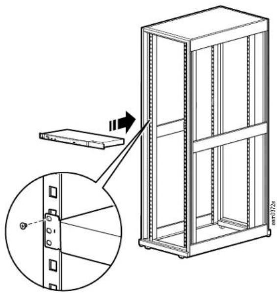
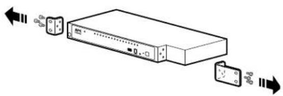
The switch can be mounted in a 19 in (1 U) rack. The mounting brackets can screw into the front or the back of the unit so that it can be attached to the front or back of the rack.
NOTE: The standard rack mount kit package does not include rack mount screws or cage nuts. If you need additional rack mount screws or cage nuts, contact your rack dealer. Use cage nuts (not provided) for racks that are not pre-threaded.
Rack mounting
- Position the switch in the front of the rack. Align the mounting bracket holes with the holes in the rack.
- Secure the mounting brackets to the rack with the screws (not supplied).
Rack Mounting - Rear
- Remove the brackets from the front of the KVM switch.
natural_image
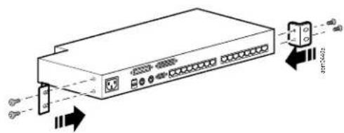
Diagram of a server rack with ports and connectors, showing signal flow direction (no text or labels)- Install the smaller bracket from the front of the unit to the back. Install the rack mounting bracket from the inventory to the other side of the rear of the unit.
natural_image
Diagram of a network switch device with ports and connectors, showing signal flow arrows (no text or labels)-
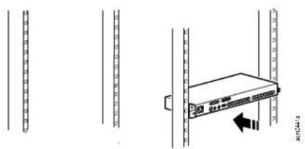
Slide the switch into the rack. Align the mounting bracket holes with the holes in the rack.
-
Secure the mounting brackets to the rear of the rack.
natural_image
Diagram showing server rack with a device and directional arrow, no text or symbols presentOptional KVM to LCD Console Mounting
The KVM switch can be mounted to a Rack LCD Console (not included). See the installation sheet for the Rack LCD Console KVM switch bracket kit for more information.
Single Level KVM Switch Installation
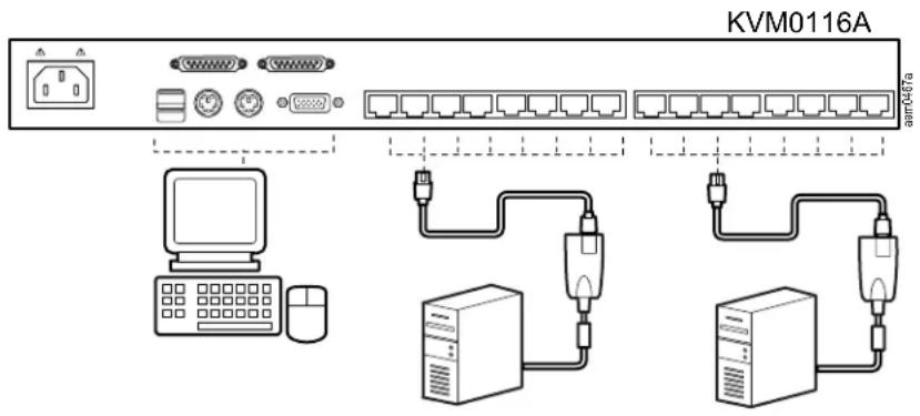
In a single level installation, there are no additional KVM switches tiered from the KVM switch. See “Cable Length Considerations” on page 13 for cable length requirements.
- Plug the console keyboards, monitors and mice into the switch's console ports. The ports are color coded and marked with icons for easy identification.
NOTE: Any combination of keyboard and mouse connections can be used. For example, a PS/2 keyboard can be used with a USB mouse. - Use Cat 5e/6 cable to connect any available KVM port to a KVM server module that is appropriate for the computer you are installing (see "KVM Server Modules and cables" on page 5).
- Plug the connectors on the KVM Adapter Cable into the appropriate server ports.
- Plug the supplied power cords into the switch's power sockets, then into an AC power source.
- Turn on the servers.
Single level installation diagram
Tiering multiple KVM switches
To control even more computers, up to 31 additional KVM switches can be tiered from the original KVM switch. As many as 512 computers can be controlled from a single console in a complete installation.
See “Connection Tables” on page 36 for a list of switches that can be installed on a tiered installation and to see the relationship between the number of computers and the number of KVM switches needed to control them.
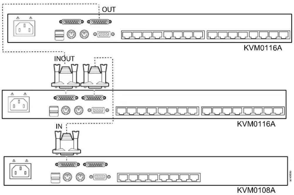
To set up a Chained tiering installation:
- Use a cable set to connect the Chain Out port of the parent KVM switch to the Chain In port of the child KVM switch (first level out to second level in, second level out to third level in, etc.).
NOTE: 1. You cannot use the Chain In port of the First Level, since it is the highest level (parent) switch. - Cable sets for chained tiering are purchased separately.
- Connect the cables to the computers and the switch according to Single Level Installation (see "Single Level KVM Switch Installation" on page 11).
- Repeat the above steps for any other switches you want to add to the chain.
- Power up the installation as follows:
e. Plug in the power cord for the first level switch. Wait for the unit to ascertain its Station ID and display it on the Station ID LED (the Station ID for the first level unit is 01, the ID for the second level unit is 02, the ID for the third level unit is 03, etc.).
f. Power on each level on the installation in turn (second level, then third level, etc.). In each case, wait for the Station ID to be ascertained and displayed before powering on the next level switch.
g. After all the KVM switches are up, power on the computers.
Chained Tiering Installation Diagram
Hardware Setup
Cable Length Considerations
NOTE: KVM server modules are also referred to as KVM adapter cables.
- Do not exceed 66 feet (20m) between the switch and the local monitor.
- To support a resolution of 1280x1024, the recommended maximum distance between the KVM switch and the KVM server module is 164 feet (50m).
Hot Plugging
Components can be removed and added to the installation by unplugging and re-plugging their cables without the need to shut down.
Change KVM Switch positions by unplugging from the old parent KVM switch and plugging into a new parent KVM switch. Afterwards, in order for the OSD menus to correspond to the change, reset the OSD. See “Reset Station IDs” on page 22.
Hot plugging KVM ports: After switching KVM ports, in order for the OSD menus to correspond to the change, you may need to reconfigure the OSD information for the new port information. The settings of the port name, operating system, and keyboard language will be restored to the KVM switch from any previously used adapter cables after they are plugged in. See "F3: SET" on page 19 and see "F4: ADM" on page 21 for port setting selections.
NOTE: 1. If a computer's operating system doesn't support hot plugging, this function may not work properly.
2. Empty ports that previously were connected to an server module will retain their prior configuration data.
Hot plugging console ports: The keyboard, monitor, and mouse can be hot plugged. When hot plugging the mouse, however, be aware of the following:
- If you unplug the mouse (to reset the mouse, for example), you must use the same mouse when you plug back in.
- If you plug in a different mouse, all the KVM switches and all the computers on the installation must be shut down for 10 seconds, then restarted (see "Powering Off and Restarting" on page 13).
- Some older operating systems may not support hot-plugging.
NOTE: If, after hot plugging (or at any other time), there is no response to keyboard and/or mouse input, perform a keyboard and mouse reset by pressing in the Reset switch. See "Reset Switch" on page 7.
Powering Off and Restarting
If it becomes necessary to power off the KVM switch, or if the switch loses power and needs to be restarted, before starting it back up, follow these procedures to prevent possible equipment issues:
- Disconnect the Cat 5e/6 cable adapters (connecting the servers) from the back of the KVM switch.
NOTE: 1. If PS/2 server modules are disconnected from the server, the server must be rebooted to re-establish the connection of the mouse and keyboard. - Unplug the power cords of any computers that have the Keyboard Power On function.
- Wait 10 seconds then power the KVM switch on. If you have shut down more than one KVM switch, power up the highest level first and work your way down to the lowest level. Wait for each KVM switch to display its station ID on the front panel LED before powering on the next one.
- After power is on to all KVM switches, plug in the Cat 5e/6 cables or power the computers on.
Port ID Numbering
Each computer on the installation is assigned a unique port ID. The port ID is a one or two segment number that is determined by the level and port number of the switch that is connected to the computer.
The first segment represents the level of the switch, the second segment represents the number of the port that the computer is plugged into. For example, if a computer is connected to KVM port 3 of a switch that is in the 12th position of the tier, it would have a port ID of 12-03.
NOTE: Single digit numbers (1-9) have a preceding zero (0).
On Screen Display (OSD) Operation
Overview
The On Screen Display (OSD) is menu driven to handle computer control and switching operations. All procedures start from the OSD Main Screen. To display the Main Screen, tap the OSD hotkey twice. The default hotkey is SCROLL LOCK . The hotkey can be changed to the [CTRL] key or the [ALT] key (see "OSD Hotkey" on page 19).
NOTE: 1. If the [CTRL] or [ALT] key is used, the same [CTRL] or [ALT] key must be pressed both times.
- The number lock and caps lock will always be on when the OSD is running.
The OSD uses a two-level (administrator/user) password system. A valid username and password is required before the OSD Main Screen opens. The default username (apc) and password (apc) is used the first time that the OSD is accessed. For security purposes, change these to something unique after you log in the first time.
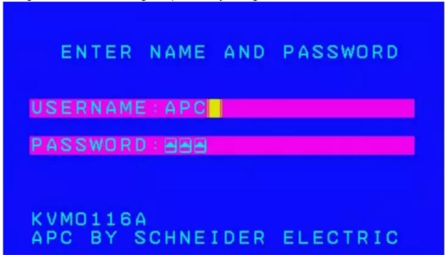
The OSD Main Screen opens in “administrator” mode after logging in with the default username and password. The administrator has access to all administrator and user functions, and can set up operations (including password authorization for the future).
OSD Main Screen "Administrator" mode
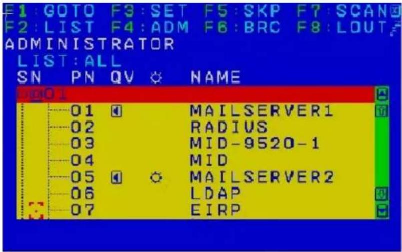
NOTE: 1. The User Main Screen does not show the F4 and F6 functions, since these are reserved for the administrator and cannot be accessed by standard users.
- Only ports that the Administrator has set to "accessible" are visible on the User Main Screen. See "Set Accessible Ports" on page 21.
OSD Navigation
- To close the OSD, press "X" (Close) at the upper right corner of the OSD Window or press [Esc].
- To Logout, press F8 or the "ZZZ" symbol at the top of the Main Screen.
- To see the ports for a particular station, press the plus sign [+] in front of the station number. The port number list opens. To close the list, press the circle symbol [o] in front of the station number.
- To move up or down through the list one line at a time, press the up and down triangle symbols or use the up and down arrow keys. If there are more list entries than room on the Main Screen, the list will scroll.
- To move up or down the list one screen at a time, press the up and down arrow symbols or use the [PAGE UP] and [PAGE DOWN] keys. If there are more list entries than room on the Main Screen, the screen will scroll.
- To focus on a port, double-click it, or move the highlight bar to it and then press [ENTER].
• After executing any action, the menu one level above automatically returns.
OSD Main Screen Headings
| Heading Explanation | |
| SN-PN | This column lists the port ID numbers (station number-port number) for all the KVM ports on the installation. The simplest method to access a particular computer is to click it, or move the highlight bar to it, and then press [ENTER]. |
| QV | If a port has been selected for Quick View scanning, an arrowhead displays in this column. |
| Sun Symbol | The computers that are powered on and are online have a sun symbol in this column. |
| Name If a port has been given a name, its name appears in this column. | |
OSD Functions
OSD functions are used for control and configuration. To access an OSD function:
- Click on a function key at the top of the Main Screen, or press a function key on the keyboard.
- Double-click or move the highlight bar over the choice in the submenu that opens and press [ENTER].
- Press [Esc] to return to the previous menu level.
F1: GOTO
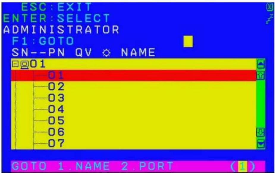
Use the GOTO function to switch directly to a port by entering the port's name or its port ID.
- To use the Name method, enter "1", the port's name, and then press [ENTER].
- To use the Port ID method, enter "2", the port ID, and then press [ENTER].
NOTE: You can enter a partial name or port ID. The screen will show all the computers to which the user has View rights that match the name or port ID pattern, regardless of the current List settings.
- To return to the OSD Main Menu without making a choice, press [Esc].
F2: LIST
Many of the switch's OSD functions only operate on the computers currently selected for listing on the Main Screen. Use this function to broaden or narrow the scope of ports that are listed.
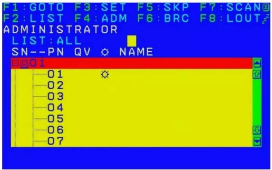
| List Meaning | |
| All Lists all of the ports on the installation | |
| Quick View Lists only the ports that have been selected as Quick View Ports | |
| Powered On Lists only the ports that have attached computers Powered On | |
| Quick View + Powered On | Lists only the ports that have been selected as Quick View Ports and that have their attached computers Powered On |
Move the highlight bar to the desired list, then press [ENTER]. An icon appears before the list to indicate that it is currently selected.
F3: SET
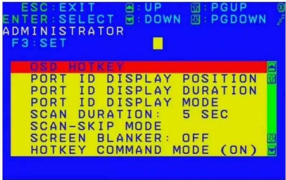
The administrator and each user can set up an individual working environment. A separate profile for each operator is stored by the OSD and is activated according to the username provided during login.
To change a setting:
-
Double-click or move the highlight bar to the setting, then press [ENTER].
-
After you select an item, a submenu with further choices opens. To make a selection, double-click it or move the highlight bar to it, then press [ENTER]. An icon appears before the selected choice.
| Setting Function | |
| OSD Hotkey | Selects which hotkey activates the OSD function: [SCROLL LOCK] [SCROLL LOCK]; [CTRL] [CTRL] or [ALT] [ALT].Since the [CTRL] or [ALT] key combinations may conflict with programs running on the computers, the default is the [SCROLL LOCK] combination. |
| Port ID Display Position | Location of the port ID on the monitor. The default is the upper left corner. To change the location: Use the mouse or the arrow keys plus PAGE UP, PAGE DOWN, HOME, END, and 5 (on the numeric keypad with NUM LOCK off), to position the port ID display, then press [ENTER] to lock the position and return to the Set submenu.Note:The setting affects the currently selected port. Change the setting for each port individually. |
| Port ID Display Duration | Determines how long a port ID displays on the monitor after a port change has taken place. There are two choices: 3 seconds and Off. |
| Port ID Display Mode | Selects how the port ID is displayed: the port number alone (PORT NUMBER), the port name alone (PORT NAME), or the port number plus the port name (PORT NUMBER + PORT NAME).The default is PORT NUMBER + PORT NAME. |
| Scan Duration | Determines how long the focus dwells on each port as it cycles through the selected ports in Auto Scan mode. Enter a value from 1-255 seconds, then press [ENTER].The default is 5 seconds. A setting of 0 (zero) disables the Scan function. |
| Scan/Skip Mode | Selects which computers will be accessed under Skip mode, and Auto Scan mode.Choices are:ALL - All the ports which have been set AccessibleQUICK VIEW - Only those ports which have been set Accessible and selected as Quick View PortsPOWERED ON - Only ports which have been set Accessible and are Powered On;QUICK VIEW + POWERED ON - Only those ports which have been set Accessible, selected as Quick View Ports, are Powered On.The default is ALL. |
| Screenblanker | If there is no input from the console for the amount of time set with this function, the screen becomes blank. Enter a value from 1-30 minutes, then press ENTER]. A setting of 0 (zero) disables the function. The default is OFF. |
| Hotkey Command Mode | Enables / Disables the Hotkey function (see “Hotkey Operation” on page 25), in case a conflict with programs running on the computers occurs. The default is ON. |
| Hotkey | Selects the Hotkey invocation keys (see“Hotkey Operation” on page 25). Choices are [NUM LOCK] + [-], OR [CTRL] + [F12].The default is [NUM LOCK] + [-]. |
| Set OSD Language | Sets the language for the OSD display. The default is English. |
| Set Console Keyboard | Sets the keyboard language mapping of the console keyboard. The default is Auto. If the switch does not automatically receive language mapping from the keyboard, it will set to English (US). |
| Set Logout Timeout | If there is no input from the console for the amount of time set with this function, the operator is automatically logged out. A login is necessary before the console can be used again. This enables other operators to gain access to the computers when the original operator is no longer accessing them, but has forgotten to log out. To set the timeout value, enter a number from 1-180 minutes, then press ENTER]. If the number is 0 (zero), this function is disabled. Default is Off.Note: This feature does not function if Set Login Mode is disabled (see page 22). |
| Activate Beeper | Choices are [Y] (Yes), or [N] (No). When activated, the beeper sounds when a port is changed, when activating the Auto Scan function, or an invalid entry is made on an OSD menu. The default is ON. |
| Set Quick View Ports | The administrator can select which ports to include as Quick View ports.To select/deselect a port as a Quick View Port, use the navigation keys to move the highlight bar to the selection, then press the [SPACEBAR]. When a port has been selected as a Quick View Port, an arrowhead displays in the QV column of the List on the Main Screen to indicate selection. When a port is deselected, the arrowhead disappears. If one of the Quick View options is chosen for the List view, only a port that has been selected here will display on the List. If one of the Quick View options is chosen for Auto Scanning, only a port that has been selected here will be Auto Scanned.The default is for no ports to be selected. |
F4: ADM
F4 is an administrator only function. Accessing this function allows the administrator to configure and control the overall operation of the OSD. To change a setting double-click it; or use the up and down arrow keys to move the highlight bar to the setting, then press [ENTER].
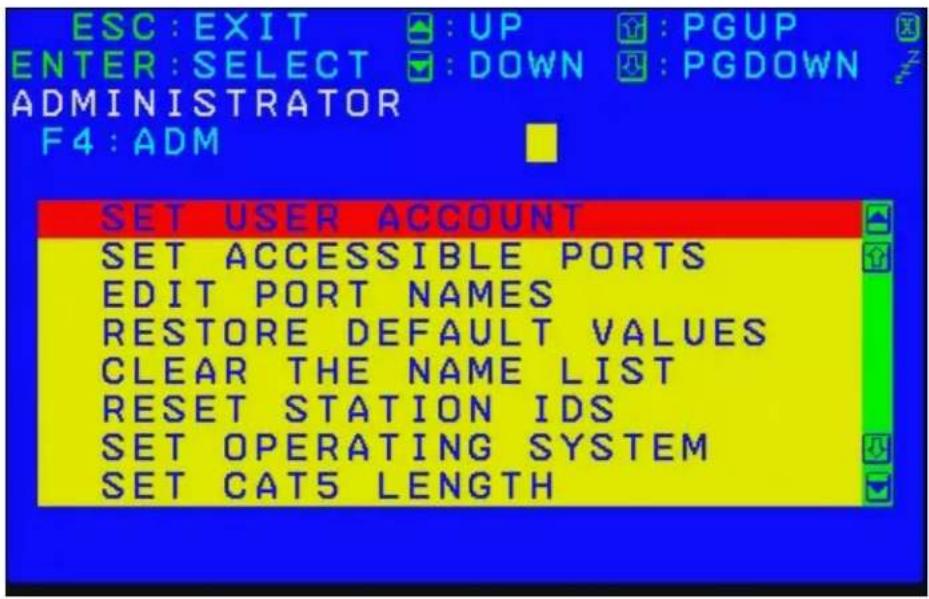
After you select an item, a submenu with further choices opens. Double-click the choice, or move the highlight bar to it, then press [ENTER]. An icon appears before the selected choice.
| Setting Function | |
| Set User Account | This function is used to set usernames and passwords for the administrator and users: one Administrator and ten user passwords can be set.After the administrator field or one of the user fields is selected, a screen that allows you to enter your username and password opens. The username and password may be up to 16 characters long, and can consist of any combination of letters and numbers (A- Z, 0-9). For each user, enter the username and password, then press [ENTER].To modify or delete a previous username and/or password, use the backspace key to erase the letters or numbers. The Sun icon indicates data is stored in the account. |
| Set Accessible Ports | This function allows the administrator to define user access to the computers on the installation on a port-by-port basis.For each user, select the target port, then press the [Spacebar] to cycle through the choices: F (Full Access), V (View Only), or N (No Access). Repeat until all access rights have been set, then press [Esc]. The default is F for all users on all ports.Note: An “N” setting means that no access rights are granted. The port will not show up on the user's list on the Main Screen. |
| Edit Port Names | To identify which computer is attached to a particular port, every port can be assigned a name. This function allows the administrator to create, modify, or delete port names.To assign a port name: Click on the port, or use the navigation keys to move the highlight bar to it, then press [ENTER]. Add the new port name, or modify/delete the old one. The maximum number of characters allowed for the port name is 14. Legal characters include all alpha characters: A-Z and numeric characters: 0-9The port names can be entered in either upper or lower case however, the OSD displays the port name only in uppercase.When you have finished editing, press [ENTER] to have the change take effect. To abort the change, press [Esc]. |
| Restore Default Values | This function will undo all changes and return the setup to the original factory default settings except for the Names settings that were assigned to the ports, which are saved. |
| Clear the Name List | This function clears the port name list. |
| Reset Station IDs | If the position of one of the stations in the chain is changed, the OSD settings will no longer correspond to the new setup.This function directs the OSD to re-scan the station positions of the entire installation and updates the OSD so that the OSD station information corresponds to the new physical layout.Note: Only the station numbers are updated. Except for the port names, all administrator settings (such as Set Accessible Ports, Set Quick View Ports, etc.), for all of the computers affected by the change, have to be manually redone. |
| Set Operating System | Specifies the operating platform of the computer attached to each port. You must configure each port on the installation. For each port, press the [SPACEBAR] to cycle through the choices (PC, Mac or Sun). Repeat until all the ports have been set, then press [Esc]. The default is PC.Note: A Sun or Mac computer may not boot when you run it for the first time unless the correct operating system is set for the port to which it is connected. |
| Set Cat 5 Length | Lets you specify how long the Cat 5e/6 cable between the port and the KVM adapter cable is. Press [SPACEBAR] to cycle through the cable length settings:S: Short - for up to 25 mM: Medium - for between 20 and 35 mL: Long - for above 35 mAn S, M, or L appears next to the port to indicate the choice. |
| Set Keyboard Language | Sets the keyboard language layout for the computers attached to each port. Press [SPACEBAR] to cycle through the choices. The default is English (US). |
| Firmware Upgrade | In order to upgrade the KVM switch and adapter cable firmware (see “Firmware Upgrade Utility” on page 32) the Firmware Upgrade mode must first be enabled with this setting. The current firmware version levels display in this menu. Select [Y] to enable Firmware Upgrade mode, or [N] to leave this menu without enabling it. |
| Adapter Upgrade | This function allows the administrator to check the firmware version of the KVM adapter cable. The current firmware version levels display in this menu. |
| Set Login Mode | This function allows the administrator to request users to login or not. When the login dialog box is disabled, the system disables the login/ logout function. If the system is re-started, the login/logout function remains disabled. |
F5: SKP
Skip backward or forward, switching the console focus from the currently active KVM Port to the previous or next available port.
- The selection of computers to be available for Skip mode switching is made with the Scan/Skip mode setting under the F3: SET function.
-
When you are in Skip mode, press:
-
Left arrow to skip to the previous port in the list
- Right arrow to skip to the next port in the list
- Up arrow to skip to the last port of the previous station in the list
- Down arrow to skip to the first port of the next station in the list
NOTE: When you skip, you only skip to the previous or next available computer that is in the Scan/Skip mode selection (see "Scan/Skip Mode" on page 20).
- If a port has been selected for Scan/Skip mode, when the focus switches to that port a left/right triangle symbol appears before its port ID display.
- While Skip mode is in effect, the console will not function normally. You must exit Skip mode in order to regain control of the console.
- To exit Skip mode, press the [SPACEBAR] or [ESC].
F6: BRC
F6 is an administrator only function. When this function is in effect, commands sent from the console are broadcast to all available computers on the installation.
This function is particularly useful for operations that need to be performed on multiple computers (such as performing a system wide shutdown, installing or upgrading software, etc.).
BRC works in conjunction with the F2: LIST function. The List function (see "F2: LIST" on page 18), is used to broaden or narrow the focus of which ports appear on the OSD Main Screen. When you broadcast a command, it is to the ports currently displayed on the OSD Main Screen.
- While BRC mode is in effect, a speaker symbol appears before the port ID display of the port that currently has the console focus.
- While BRC mode is in effect, the mouse will not function normally. Exit BRC mode in order to regain control of the mouse.
- To exit BRC mode, invoke the OSD (with the OSD Hotkey), then click the F6 field, or press [F6].
F7: SCAN
This function automatically switches among the available computers at regular intervals so that their activity can be monitored without switching manually.
- The selection of computers to be included for Auto Scanning is made with the Scan/Skip mode setting under the F3: SET function (see "F3: SET" on page 19).
- The amount of time that each port displays is set with the Scan Duration setting under the F3: SET function (see "F3: SET" on page 19).
- As each computer is accessed, an "S" appears in front of the port ID display to indicate that it is being accessed under Auto Scan mode.
- While you are in Auto Scan mode, you can pause the scanning in order to keep the focus on a particular computer either by pressing [P], or with a left-click of the mouse. To resume scanning, press any key or left-click again (see "Auto Scan Mode Switching" on page 26).
- While Auto Scan mode is in effect, the console will not function normally. Exit Auto Scan mode in order to regain control of the console.
- To exit Auto Scan mode, press the [SPACEBAR] or [Esc].
F8: LOGOUT
Click in the F8 field, or press [F8] to log out of the OSD and blank the console screen. This is different from deactivating the OSD when from the Main Screen by pressing [Esc].
With this function you must log in all over again to regain access to the OSD. (When [Esc] is pressed, you just tap the OSD Hotkey a to re-enter the OSD.)
NOTE: 1. When you reenter the OSD after logging out, the screen stays blank except for the login dialog box. Before continuing, enter your username and password (see "On Screen Display (OSD) Operation" on page 15). If your login has been disabled by the administrator, the F8 function is also disabled.
2. If you re-enter the OSD after logging out, and immediately use [Esc] to deactivate the OSD without selecting a port from the OSD menu, a Null Port message displays on the screen. The OSD hotkey will open the OSD Main Screen.
Hotkey Operation Hotkey Port Control
Hotkey port control allows you to provide KVM focus to a particular computer directly from the keyboard. The KVM switch has the following Hotkey port control features:
- Selecting the Active Port
• Auto Scan Mode Switching - Skip Mode Switching
• Computer Keyboard / Mouse Reset
The following settings can also be controlled in Hotkey mode:
- Setting the Beeper
- Setting the Quick Hotkey
- Setting the OSD Hotkey
- Setting the Port Operating System
- Restoring the OSD Default Values
Invoking Hotkey Mode
All Hotkey operations begin by invoking Hotkey mode. To invoke Hotkey mode two possible keystroke sequences shown below can be used. Only one of the key sequences below can be operational (see "Setting the Hotkey Key Combination" on page 27).
$$ [ \text { Num Lock } ] + [ - ] $$
$$ [ \mathrm{CTRL} ] + [ \mathrm{F12} ] $$
- Hold down the [Num Lock] key.
- Press and release the [MINUS] key.
-
Release the [Num Lock] key.
-
Hold down the [CTRL] key.
- Press and release the [F12] key.
- Release the [CTRL] key.
Hotkey mode environment
When Hotkey mode is active:
- A command line appears on the monitor screen. The command line prompt is the word Hotkey in white text on a blue background, and displays the subsequent Hotkey information that you enter.
- Ordinary keyboard and mouse functions are suspended. Only Hotkey compliant keystrokes can be input.
Exiting hotkey mode
Press [Esc] to exit Hotkey mode. Make sure that the Hotkey Command Mode function is enabled and that the appropriate Hotkey has been entered. See "Hotkey Operation" on page 25.
Selecting the Active Port
Each computer port is assigned a port ID (see "Port ID Numbering" on page 14). Any computer can be directly accessed with a Hotkey combination that specifies the port ID that the computer is connected to. To select the active port:
- Invoke Hotkey mode: [NUM LOCK] + [-] OR [CTRL] + [F12].
- Enter the port ID. The port ID numbers display on the command line as you enter them. Use [BACKSPACE] to erase any mistakes.
- Press [ENTER] to focus the KVM switches to the designated computer and automatically exits Hotkey mode.
NOTE: In Hotkey mode, the KVM focus will not switch to a port if an invalid switch or port number is entered. The Hotkey command line will continue to display until a valid switch and port number combination is entered, or Hotkey mode is exited.
Auto Scan Mode Switching
Auto Scan automatically switches at regular intervals through all the active computer ports accessible to the currently logged on user. This allows activity to be monitored automatically.
Setting the scan interval
The amount of time Auto Scan stays focused on each port is set with the "Scan Duration" setting of the OSD F3: SET function (see "F3: SET" on page 19). The scan interval can be changed before activating Hotkey Auto Scanning by entering the following Hotkey combination:
- Invoke Hotkey mode: [NUM LOCK] + [-] or [CTRL] + [F12].
- Enter [A][N]: Where [A] is the letter A, and [N] is a number from 1-255 that represents the length of the focus time in seconds. The letter A and the numbers display on the command line as you enter them. Use [BACKSPACE] to erase mistakes.
- Press [ENTER] to exit Hotkey mode. Auto Scanning can now be started.
Invoking Auto Scan
To invoke Auto Scanning mode, enter the following Hotkey combination:
- Invoke Hotkey mode: [NUM LOCK] + [-] or [CTRL] + [F12].
- Press [A] + [ENTER].
- While in Auto Scan mode, scanning can be paused to keep the focus on a particular computer by pressing [P]. When paused, the Command Line displays "Auto Scan: Paused."
- To keep the focus on a particular computer, pausing is more convenient than exiting Auto Scan mode. When scanning resumes, it starts at the computer where scanning was paused. If Auto Scanning is exited and then restarted, it starts with the first computer on the installation.
Press any key to resume scanning starting from the computer where scanning was paused.
- While Auto Scan mode is operating, ordinary keyboard and mouse functions are suspended. Only Auto Scan compliant keystrokes can be input. Exit Auto Scan mode to regain normal control of the console.
Exiting Auto Scan
To exit Auto Scan press [Esc] or [SPACEBAR]. Scanning stops when Auto Scan is exited.
Skip Mode Switching
Switch between computers to manually monitor them. Focus on a particular port for as long as you like, as opposed to auto-scanning, which automatically switches the port focus after a fixed interval.
Entering skip mode
To enter Skip mode, enter the following Hotkey combination:
- Invoke Hotkey mode: [Num Lock] + [-] or [CTRL] + [F12].
- Press one of the Arrow keys.
-
After you press one of the arrow keys, Hotkey mode is automatically exited and Skip mode entered. Switch ports as follows:
-
Left arrow skips to the first accessible port (see "Scan/Skip Mode" on page 20 for information regarding accessible ports)
- Right arrow skips to the next accessible port
- Up arrow skips to the last accessible port of the previous station
-
Down arrow skips to the first accessible port of the next station
-
Once in Skip mode, continue skipping by pressing the arrow keys. The [Num Lock] + [-] combination does not have to be used again.
-
While Skip mode is engaged, ordinary keyboard and mouse functions are suspended. Only Skip mode compliant keystrokes can be input. Exit Skip mode to regain normal control of the console.
Exiting skip mode
To exit Skip mode, press [Esc] or [SPACEBAR].
Computer Keyboard/Mouse Reset
If either the keyboard or mouse stop functioning on the computer connected to the currently selected port, you can perform a keyboard/mouse reset on the computer.
- Invoke Hotkey mode: [Num Lock] + [-] or [CTRL] + [F12]
- Press [F5]. After pressing [F5] Hotkey mode is automatically exited and keyboard and mouse control on the computer connected to the KVM port is regained. If keyboard/mouse control on the computer fails after pressing [F5], perform a system reset (see "Reset Switch" on page 7).
This function is essentially the same as unplugging and replugging the keyboard and mouse on the target computer.
Setting the Hotkey Beeper ON/OFF
Turn the beeper (see "Activate Beeper" on page 20) on and off with Hotkeys:
- Invoke Hotkey mode: [Num Lock] + [-] or [CTRL] + [F12].
- Press [B] to turn the beeper on or off. The command line displays "Beeper On" or "Beeper Off" for one second; then the message disappears Hotkey mode is automatically exited.
Setting the Hotkey Key Combination
Switch the keys used to enter the Hotkey Mode (see "Hotkey Operation" on page 25)
- Invoke Hotkey mode: [NUM LOCK] + [-] or [CTRL] + [F12].
- Press [H] to display the command line "Hotkey has Been Changed" for one second, then the message closes and Hotkey mode is automatically exited.
Setting the OSD Hotkey combination
Hotkeys used to access the OSD (see "OSD Hotkey" on page 19) can be switched between [SCROLL LOCK], [SCROLL LOCK], [CTRL], [CTRL], and [ALT], [ALT].
- Invoke Hotkey mode: [NUM LOCK] + [-] or [CTRL] + [F12].
- Press [T] to display the command line "Hotkey has Been Changed" for one second then the message closes and Hotkey mode is automatically exited.
Setting the Port Operating System
Match a port's operating system configuration to that of the computer attached to the port.
- Invoke Hotkey mode: [Num Lock] + [-] or [CTRL] + [F12] .
- Press one of the following function keys:
| Key | Description |
| F1 | Sets the Port OS to Windows |
| F2 | Sets the Port OS to Mac |
| F3 | Sets the Port OS to Sun |
After pressing a function key, Hotkey mode is automatically exited.
Restore the Default Values
Restore the KVM switch default values (see "Restore Default Values" on page 22) using this administrator-only Hotkey.
- Invoke Hotkey mode: [Num Lock] + [-] or [CTRL] + [F12] .
- Press [R].
- Press [ENTER] to display the command line "Reset to Default Setting" for three seconds, then the message closes and Hotkey mode is automatically exited.
Hotkey Summary Table
| [NUM LOCK] + [-] OR [CTRL] + [F12] | [A] [ENTER] | Invokes Auto Scan mode.When Auto Scan mode is in effect, [P] or left-click pauses auto-scanning.When auto-scanning is paused, pressing any key or another left-click resumes auto-scanning |
| [B] Toggles the Beeper On or Off. | ||
| [ESC] or [SPACEBAR] | Exits hotkey mode. | |
| [F1] Sets the Operating System to Windows | ||
| [F2] Sets the Operating System to Mac | ||
| [F3] Sets the Operating System to Sun | ||
| [F5] | Performs a keyboard/mouse reset on the target computer. | |
| [H] Toggles the Hotkey invocation keys. | ||
| [Port ID] [ENTER] | Switches access to the computer that corresponds to the Port ID. | |
| [R] [ENTER] | Administrator-only Hotkey. It returns the switch's settings to their default values. | |
| [T] | Toggles the OSD Hotkey between [CTRL] [CTRL] and [SCROLL LOCK] [SCROLL LOCK]. | |
| 3 | Invokes Skip Mode and skips from the current port to the first accessible port previous to it. | |
| 4 | Invokes Skip Mode and skips from the current port to the next accessible port. | |
| 5 | Invokes Skip Mode and skips from the current port to the last accessible port of the previous Station. | |
| 6 | Invokes Skip Mode and skips from the current port to the first accessible port of the next Station. | |
Keyboard Emulation
Mac Keyboard
The PC compatible (101/104 key) keyboard can emulate the functions of the Mac keyboard. The emulation mappings are listed in the table below.
| PC Keyboard Mac Keyboard | |
| [SHIFT] SHIFT | |
| [CTRL] CTRL | |
| [x645] |  |
| [CTRL] [1] |  |
| [CTRL] [2] |  |
| [CTRL] [3] |  |
| [CTRL] [4] |  |
| [ALT] ALT | |
| [PRINT SCREEN] F13 | |
| [SCROLL LOCK] F14 | |
| [w2KD] | = |
| [ENTER] RETURN | |
| [BACKSPACE] DELETE | |
| [INSERT] HELP | |
| [CTRL] | F15 |
NOTE: When using key combinations, press and release the first key [CTRL], then press and release the activation key.
Sun Keyboard
The PC compatible (101/104 key) keyboard can emulate the functions of the Sun keyboard when the Control key [CTRL] is used in conjunction with other keys. The corresponding functions are shown below.
| PC Keyboard Sun Keyboard | |
| [CTRL] [T] | Stop |
| [CTRL] [F2] | Again |
| [CTRL] [F3] | Props |
| [CTRL] [F4] | Undo |
| [CTRL] [F5] | Front |
| [CTRL] [F6] | Copy |
| [CTRL] [F7] | Open |
| [CTRL] [F8] | Paste |
| [CTRL] [F9] | Find |
| [CTRL] [F10] | Cut |
| [CTRL] [1] |  |
| [CTRL] [2] | 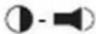 |
| [CTRL] [3] | 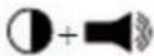 |
| [CTRL] [4] | [X829] |
| [CTRL] [H] | Help |
 | Compose |
 | Meta |
NOTE: When using key combinations, press and release the first key (CTRL), then press and release the activation key.
Firmware Upgrade Utility
Introduction
The Windows-based Firmware Upgrade Utility provides an automated process for upgrading the KVM switch and compatible adapter cable firmware. The program comes as part of a Firmware Upgrade Package that is specific for each device.
The latest revisions of new firmware for the KVM switch, and supported KVM Adapter Cables are posted as Firmware Upgrade Packages on our website. Check the website regularly to find the latest firmware packages and information relating to them.
NOTE: 1. A single upgrade package contains the upgrade files for the Main Board and all the supported KVM Adapter Cables.
- KVM Adapter Cables are referred to as I/O Modules in some dialog boxes.
Before you begin
To prepare for the firmware upgrade:
- From a computer that is not part of your KVM installation go to www.apc.com and choose the model name that relates to your device to receive a list of available Firmware Upgrade Packages.
- Choose the Firmware Upgrade Package you want to install (usually the most recent), and download it to your computer.
- Use the firmware upgrade cable (provided with this unit), to connect a COM port on your computer to the firmware upgrade port of your device. See "Firmware Upgrade Port" on page 7 for details.
NOTE: On a tiered installation, connect the cable to the first station (master) unit. The tiered levels that are the same model will receive the upgrade through the chaining cables.
-
From your KVM switch console, open the OSD (see "On Screen Display (OSD) Operation" on page 15) and select the "F4:ADM" function.
-
Scroll down to "Firmware Upgrade." Press [ENTER], then press [Y] (Yes) to start the Firmware Upgrade mode.
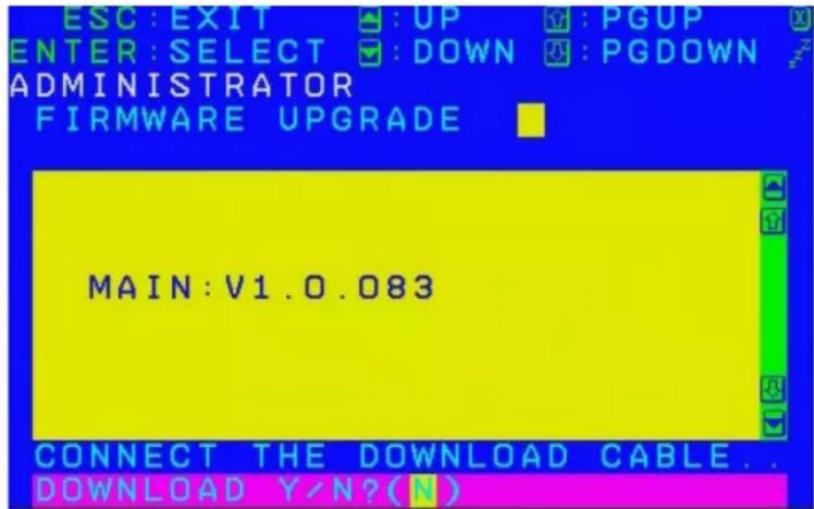
NOTE: 1. The upgrade to the KVM Adapter Cables takes place through the Cat 5e/6 cable that connects the adapter cable to the KVM switch, so there is no separate firmware upgrade cable to attach.
-
Adapter cable firmware selected with the upgrade utility will upgrade in a single session all connected adapter cable models that match the firmware type.
-
Or, scroll down to "Adapter Upgrade". Press [ENTER], then press [Y] to start the Firmware Upgrade mode for Adapter Cables only.
Performing the Upgrade
Starting the upgrade
To upgrade your firmware:
-
To run the downloaded Firmware Upgrade Package file, double click the file icon, or open a command line and enter the full path to it.
-
The Utility checks to make sure the KVM switch is in the Firmware Upgrade Mode and then lists all needed firmware preselected in the Device List panel.
NOTE: 1. The Device List lists all KVM Server Modules that require upgrading.
-
If the Utility fails to list any firmware, check that the KVM switch is connected and in the Firmware Upgrade Mode. The Firmware Package may be corrupted or the wrong version. Obtain a new copy of the file and retry.
-
Select MAIN to upgrade the firmware for the Main Board. Deselect any KVM Server Modules that will not be upgraded. After making your selection(s), click Next to perform the upgrade.
d. Check Firmware Version - When selected, the utility compares the Main Board firmware level with the upgrade files MAIN. If the device versions are higher than the upgrade versions a dialog box informs you and gives you the option to continue or cancel.
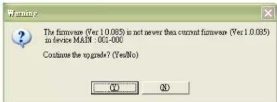
e. If Check Firmware Version was not enabled, the upgrade files are installed without checking their level.
f. Status messages appear in the Status Messages panel and the progress toward completion is shown on the Progress bar as the upgrade proceeds.
g. To abort the upgrade procedure before it completes, click Cancel.
h. If the upgrade is cancelled before completion, a warning dialog box will state that the upgrade will not finish and offers the option to proceed or abort the cancel operation. The Mainboard and OSD firmware may be missing or corrupted upon rebooting the switch.
NOTE: To recover from missing or corrupt firmware, see "Firmware Upgrade Utility" on page 32.
Upgrade succeeded
After the upgrade has completed, a screen opens informing you that the procedure was successful.
Click Finish to close the Firmware Upgrade Utility.
NOTE: At the completion of the upgrade, the KVM switch will restart.
Upgrade failed
If the upgrade failed to complete successfully a dialog box appears asking if you want to retry. Click Yes to retry. If you press No, the Upgrade Failed screen appears.
Click Cancel to close the Firmware Upgrade Utility.
Firmware Upgrade Recovery
Should the firmware on the switch be missing or corrupted, it may not be possible to operate or boot the switch. Corruption of files can occur due to:
- Canceling the Firmware Upgrade mode before it has finished.
- An interruption of the firmware upgrade.
- The firmware upgrade procedure failing.
Main board firmware upgrade recovery
To perform a firmware upgrade recovery, do the following:
- On the KVM Switch slide the Firmware Upgrade Recovery Switch (see "Firmware Upgrade Recovery Switch" on page 7) to the Recover position.
- Power off and restart the switch (see "Powering Off and Restarting" on page 13).
- Proceed with the firmware upgrade (see "Performing the Upgrade" on page 33).
- When the upgrade ends, power off the switch
- Slide the Firmware Upgrade Recovery Switch back to the Normal position.
- Power on the switch.
NOTE: If one of the child KVM units fails to upgrade successfully, unchain it from the installation and perform the recovery and upgrade operation on it independently. After it has been successfully upgraded, plug it back into the chain
Server Module firmware upgrade recovery
To perform an Server Module firmware upgrade recovery:
- Unplug the Server Module from the computer it is connected to.
- Slide the Firmware Upgrade Recovery Switch (located next to the RJ45 connector) to the Recover position.
- Plug the Server Module back into the computer.
- From your KVM switch console, bring up the OSD (see "On Screen Display (OSD) Operation" on page 15) and select the "F4: ADM" function.
- Scroll down to FIRMWARE UPGRADE. Press [ENTER].
- Press [Y] to invoke the Upgrade mode.
- Proceed with the firmware upgrade (see "Performing the Upgrade" on page 33).
- After the upgrade completes and the switch restarts, unplug the Server Module from the computer and slide the Firmware Upgrade Recovery Switch back to the Normal position.
- Plug the Server Module back into the computer.
Troubleshooting
Overview
Operation problems can be due to a variety of causes. The first step in solving them is to make sure that all cables are securely attached and seated completely in their sockets.
In addition, updating the product's firmware may solve problems that have been discovered and resolved since the prior version was released. If your product is not running the latest firmware version, we strongly recommend that you upgrade (see "Firmware Upgrade Utility" on page 32).
| Symptom Action | |
| Mouse and/or Keyboard not responding | Unplug the cable from the console port, then plug it back in. |
| All Station IDs display as 01 | Station 1 suddenly lost power. Wait a few seconds for the system to re-initialize the station sequence and display the proper IDs.Perform a reset on station ID (see “Reset Station IDs” on page 22).Unplug the chaining cable, then plug it back in. |
OSD Factory Default Settings
| Setting Default | |
| OSD Hotkey | [SCROLL LOCK] [SCROLL LOCK] |
| Port ID Display Position | Upper Left Corner |
| Port ID Display Duration | 3 Seconds |
| Port ID Display Mode The Port Number plus the Port Name | |
| Scan Duration 5 Seconds | |
| Scan/Skip Mode All | |
| Screen Blanker OFF | |
| Hotkey Command Mode | ON |
| Hotkey | [Num Lock] + [-] |
| Logout Timeout OFF | |
| Beeper ON | |
| Accessible Ports F (Full Access) For all Users on all Ports | |
| Operation Mode Share | |
| OSD Language English | |
Connection Tables
The following table indicates the relationship between the number of KVM0108A / KVM0116A units and the number of computers that they control
KVM0108A
| No. | Computers No. | Computers No. | Computers No. | Computers No. | Computers | |||
| 1 | 1-8 | 9 | 65 - 72 | 17 | 129 - 136 | 25 | 193 - 200 | |
| 2 | 9 - 16 | 10 | 73 - 80 | 18 | 137 - 144 | 26 | 201 - 208 | |
| 3 | 17 - 24 | 11 | 81 - 88 | 19 | 145 - 152 | 27 | 209 - 216 | |
| 4 | 25 - 32 | 12 | 89 - 96 | 20 | 153 - 160 | 28 | 217 - 224 | |
| 5 | 33 - 40 | 13 | 97 - 104 | 21 | 161 - 168 | 29 | 225 - 232 | |
| 6 | 41 - 48 | 14 | 105 - 112 | 22 | 169 - 176 | 30 | 233 - 240 | |
| 7 | 49- 56 | 15 | 113 - 120 | 23 | 177- 184 | |||
| 8 | 57 - 64 | 16 | 121 - 128 | 24 | 185 - 192 | 32 | 249 - 256 | |
KVM0116A
| No. | Computers | No. | Computers | No. | Computers | No. | Computers | ||||
| 1 | 1 - 16 | 9 | 129 - 144 | 17 | 25 | - 272 | 25 | 385 - 400 | |||
| 2 | 17 - 32 | 10 | 145 - | 160 | 18 | 273 - 288 | 26 | 401 - 416 | |||
| 3 | 33 - 48 | 11 | 161 - | 176 | 19 | 289 - 304 | 27 | 417 - 432 | |||
| 4 | 49 - 64 | 12 | 177 - | 192 | 20 | 305 - 320 | 28 | 433 - 448 | |||
| 5 | 65 - 80 | 13 | 193 - | 208 | 21 | 321 - 336 | 29 | 449 - 464 | |||
| 6 | 81 - 96 | 14 | 209 - | 224 | 22 | 337 - 352 | 30 | 465 - 480 | |||
| 7 | 97 - 112 | 15 | 225 - 240 | 23 | 353 - 368 | 31 | 481 - 496 | ||||
| 8 | 113 - 128 | 16 | 241 - 256 | 24 | 369 - 384 | 32 | 497 - 512 | ||||
Specifications
| Function KVM0108A | KVM0116A | |||
| Computer Connections | Direct 8 16 | |||
| Max 256 512 | ||||
| Connectors | Console Ports (back) | Keyboard | 2 x 6-pin Mini-DIN Female (Purple)2 x USB (Black) | 2 x 6-pin Mini-DIN Female (Purple)2 x USB T (Black) |
| Video 2 x | HDB-15 Female (Blue) 2 x HDB-15 Female (Blue) | |||
| Mouse | 2 x 6-pin Mini-DIN Female (Green)2 x USB (Black) | 2 x 6-pin Mini-DIN Female (Green)2 x USB (Black) | ||
| Console Ports (front) | Rack LCD Console | 15 pin DIN Female 15 pin DIN Female | ||
| KVM Port 8 x RJ-45 (Black) 16 x RJ-45 (Black) | ||||
| Power 1 x IEC C14 1 x | EC C14 | |||
| Chain In/Out | Serial Female | Serial Female | ||
| Switches | Reset 1 x Recessed Pushbutton 1 x Recessed Pushbutton | |||
| LEDs | Port | 16 (Green/Red/Orange) | 16 (Green/Red/Orange) | |
| Power 1 (Blue) | 1 (Blue) | |||
| Station ID | 1 (Orange) | 1 (Orange) | ||
| Video | 1600 x1200 @ 60Hz | 1600 x1200 @ 60Hz | ||
| I/P Rating | 100-240 VAC, 50/60 Hz; 1.0A | 100-240 VAC, 50/60 Hz; 1.0A | ||
| Power Consumption | 20.6 W Max. | 20.6 W Max. | ||
| Environment | Operating Temp. | 0 - 50°C (32°F - 122°F) | 0 - 50°C (32°F - 122°F) | |
| Storage Temp. | -20°C - 60°C (-4°F - 140°F) | -20°C - 60°C (-4°F - 140°F) | ||
| Humidity | 0 - 80% RH, Non-condensing | 0 - 80% RH, Non-condensing | ||
| Physical Properties | Housing | Metal | Metal | |
| Weight / Shipping Weight | 2.4 kg (5.28 lbs) / 3.9 kg (8.58 lbs) | 2.4 kg (5.28 lbs) / 3.9 kg (8.58 lbs) | ||
| Dimensions L x W x H | 18.8 cm (7.4 in) x42.4 cm (16.69 in)x4.3 cm (1.69 in)(19" 1 U) | 18.8 cm (7.4 in) x42.4 cm (16.69 in) x4.3 cm (1.69 in)(19" 1 U) | ||
Radio Frequency Interference
Changes or modifications to this unit not expressly approved by the party responsible for compliance could void the user's authority to operate this equipment.
USA—FCC
This equipment has been tested and found to comply with the limits for a Class A digital device, pursuant to part 15 of the FCC Rules. These limits are designed to provide reasonable protection against harmful interference when the equipment is operated in a commercial environment. This equipment generates, uses, and can radiate radio frequency energy and, if not installed and used in accordance with this user manual, may cause harmful interference to radio communications. Operation of this equipment in a residential area is likely to cause harmful interference. The user will bear sole responsibility for correcting such interference.
Canada—ICES
This Class A digital apparatus complies with Canadian ICES-003.
This device is a Class A device. Using this device in a home environment may cause radio wave interference. In this case, the user may be required to take appropriate measures.
This product is in conformity with Electromagnetic Compatibility (EMC) requirements set forth by the EU directive 2014/30/EU of the European parliament and of the concil of 26 February 2014 on the hamronization of the laws of the Member States relating to electromagnetic compatibility.
This Product has been tested and found to comply with the limits for Class A Information Technology Equipment according to CISPR 32/EN55032:2015 for Emissions and EN 55024:2010+A1:2015 for Immunities
Attention: This is a Class A product. In a domestic/residential environment this product may cause raido interference in which the user may be required to take adequate measures.
United Kingdom
This product is in conformity with Electromagnetic Compatibility Regulations 2016 of the UK Legislation as applied to products being supplied in or into Great Britain from 1 January 2021.
This product has been tested and found to comply with the limits for Class A Information Technology Equipment according to CISPR 32/EN 55032:2015 for Emissions and EN 55024:2010+A1:2015 for Immunities.
Attention: This is a Class A product. In a domestic/residential environment this product may cause radio interference in which the user may be required to take adequate measures.
Warranty
Two-Year Factory Warranty
This warranty applies only to the products you purchase for your use in accordance with this manual.
Terms of warranty
Schneider Electric warrants its products to be free from defects in materials and workmanship for a period of two years from the date of purchase. Schneider Electric will repair or replace defective products covered by this warranty. This warranty does not apply to equipment that has been damaged by accident, negligence or misapplication or has been altered or modified in any way. Repair or replacement of a defective product or part thereof does not extend the original warranty period. Any parts furnished under this warranty may be new or factory-remanufactured.
Non-transferable warranty
This warranty extends only to the original purchaser who must have properly registered the product. The product may be registered at the Schneider Electric Web site, www.apc.com.
Exclusions
Schneider Electric shall not be liable under the warranty if its testing and examination disclose that the alleged defect in the product does not exist or was caused by end user's or any third person's misuse, negligence, improper installation or testing. Further, Schneider Electric shall not be liable under the warranty for unauthorized attempts to repair or modify wrong or inadequate electrical voltage or connection, inappropriate on-site operation conditions, corrosive atmosphere, repair, installation, exposure to the elements, Acts of God, fire, theft, or installation contrary to Schneider Electric recommendations or specifications or in any event if the Schneider Electric serial number has been altered, defaced, or removed, or any other cause beyond the range of the intended use.
THERE ARE NO WARRANTIES, EXPRESS OR IMPLIED, BY OPERATION OF LAW OR OTHERWISE, OF PRODUCTS SOLD, SERVICED OR FURNISHED UNDER THIS AGREEMENT OR IN CONNECTION HEREWITH. SCHNEIDER ELECTRIC DISCLAIMS ALL IMPLIED WARRANTIES OF MERCHANTABILITY, SATISFACTION AND FITNESS FOR A PARTICULAR PURPOSE. SCHNEIDER ELECTRIC EXPRESS WARRANTIES WILL NOT BE ENLARGED, DIMINISHED, OR AFFECTED BY AND NO OBLIGATION OR LIABILITY WILL ARISE OUT OF, SCHNEIDER ELECTRIC RENDERING OF TECHNICAL OR OTHER ADVICE OR SERVICE IN CONNECTION WITH THE PRODUCTS. THE FOREGOING WARRANTIES AND REMEDIES ARE EXCLUSIVE AND IN LIEU OF ALL OTHER WARRANTIES AND REMEDIES. THE WARRANTIES SET FORTH ABOVE CONSTITUTE SCHNEIDER ELECTRIC'S SOLE LIABILITY AND PURCHASER'S EXCLUSIVE REMEDY FOR ANY BREACH OF SUCH WARRANTIES. SCHNEIDER ELECTRIC WARRANTIES EXTEND ONLY TO PURCHASER AND ARE NOT EXTENDED TO ANY THIRD PARTIES.
IN NO EVENT SHALL SCHNEIDER ELECTRIC, ITS OFFICERS, DIRECTORS, AFFILIATES OR EMPLOYEES BE LIABLE FOR ANY FORM OF INDIRECT, SPECIAL, CONSEQUENTIAL OR PUNITIVE DAMAGES, ARISING OUT OF THE USE, SERVICE OR INSTALLATION, OF THE PRODUCTS, WHETHER SUCH DAMAGES ARISE IN CONTRACT OR TORT, IRRESPECTIVE OF FAULT, NEGLIGENCE OR STRICT LIABILITY OR WHETHER SCHNEIDER ELECTRIC HAS BEEN ADVISED IN ADVANCE OF THE POSSIBILITY OF SUCH DAMAGES. SPECIFICALLY, SCHNEIDER ELECTRIC IS NOT LIABLE FOR ANY COSTS, SUCH AS LOST PROFITS OR REVENUE, LOSS OF EQUIPMENT, LOSS OF USE OF EQUIPMENT, LOSS OF SOFTWARE, LOSS OF DATA, COSTS OF SUBSTITUENTS, CLAIMS BY THIRD PARTIES, OR OTHERWISE.
NO SALESMAN, EMPLOYEE OR AGENT OF SCHNEIDER ELECTRIC IS AUTHORIZED TO ADD TO OR VARY THE TERMS OF THIS WARRANTY. WARRANTY TERMS MAY BE MODIFIED, IF AT ALL, ONLY IN WRITING SIGNED BY AN SCHNEIDER ELECTRIC OFFICER AND LEGAL DEPARTMENT.
Warranty claims
Customers with warranty claims issues may access the Schneider Electric customer support network through the Support page of the Schneider Electric Web site, www.apc.com/support. Select your country from the country selection pull-down menu at the top of the Web page. Select the Support tab to obtain contact information for customer support in your region.
Worldwide Customer Support
Customer support for this product is available at www.apc.com.
APC
70 Mechanic Street
Foxboro, MA 02035
USA
www.apc.com
As standards, specifications, and designs change from time to time, please ask for confirmation of the information given in this publication.
© 2020–2022 Schneider Electric. APC and the APC logo are trademarks of Schneider Electric SE or its subsidiaries. All other brands may be trademarks of their respective owners.
990-4406D-001
- Schneider Electric Legal Disclaimer
- Contents
- General Information ....1
- Installation 9
- On Screen Display (OSD) Operation 15
- Hotkey Operation ....25
- General Information
- Overview
- KVM0108A and KVM0116A KVM Switches
- Features
- Safety
- Safety map
- DANGER
- WARNING
- CAUTION
- NOTICE
- KVM Safety
- HAZARD OF ELECTRIC SHOCK
- ▲CAUTION
- INJURY OR EQUIPMENT DAMAGE
- Taking Delivery
- Accessory Inventory
- Requirements
- Console
- Computers
- KVM Server Modules and cables
- Supported operating systems
- Maximum server connections
- Component Identification
- Front
- Rear
- Installation
- Rack Mounting
- Rack Mounting - Rear
- Optional KVM to LCD Console Mounting
- Single Level KVM Switch Installation
- Tiering multiple KVM switches
- To set up a Chained tiering installation:
- Chained Tiering Installation Diagram
- Hardware Setup
- Cable Length Considerations
- Hot Plugging
- Powering Off and Restarting
- Port ID Numbering
- On Screen Display (OSD) Operation
- OSD Navigation
- OSD Main Screen Headings
- OSD Functions
- F1: GOTO
- F2: LIST
- F3: SET
- F4: ADM
- F5: SKP
- F6: BRC
- F7: SCAN
- F8: LOGOUT
- Hotkey Operation Hotkey Port Control
- Invoking Hotkey Mode
- Hotkey mode environment
- Exiting hotkey mode
- Selecting the Active Port
- Auto Scan Mode Switching
- Setting the scan interval
- Invoking Auto Scan
- Exiting Auto Scan
- Skip Mode Switching
- Entering skip mode
- Exiting skip mode
- Computer Keyboard/Mouse Reset
- Setting the Hotkey Beeper ON/OFF
- Setting the Hotkey Key Combination
- Setting the OSD Hotkey combination
- Setting the Port Operating System
- Restore the Default Values
- Keyboard Emulation
- Mac Keyboard
- Sun Keyboard
- Firmware Upgrade Utility
- Introduction
- Before you begin
- Performing the Upgrade
- Starting the upgrade
- Upgrade succeeded
- Upgrade failed
- Firmware Upgrade Recovery
- Main board firmware upgrade recovery
- Server Module firmware upgrade recovery
- Troubleshooting
- OSD Factory Default Settings
- Connection Tables
- Radio Frequency Interference
- USA—FCC
- Canada—ICES
- United Kingdom
- Warranty
- Two-Year Factory Warranty
- Terms of warranty
- Non-transferable warranty
- Exclusions
- Warranty claims
- Worldwide Customer Support
Brand : APC
Model : KVM0108A
Category : Computer Adapter